EP1745894A2 - Table mount holder for tool - Google Patents
Table mount holder for tool Download PDFInfo
- Publication number
- EP1745894A2 EP1745894A2 EP06117469A EP06117469A EP1745894A2 EP 1745894 A2 EP1745894 A2 EP 1745894A2 EP 06117469 A EP06117469 A EP 06117469A EP 06117469 A EP06117469 A EP 06117469A EP 1745894 A2 EP1745894 A2 EP 1745894A2
- Authority
- EP
- European Patent Office
- Prior art keywords
- base
- tool
- holder
- members
- scissors
- Prior art date
- Legal status (The legal status is an assumption and is not a legal conclusion. Google has not performed a legal analysis and makes no representation as to the accuracy of the status listed.)
- Withdrawn
Links
- 230000003213 activating effect Effects 0.000 claims description 5
- 230000014759 maintenance of location Effects 0.000 claims description 5
- 230000000295 complement effect Effects 0.000 claims description 2
- 230000002708 enhancing effect Effects 0.000 claims 3
- 239000000463 material Substances 0.000 description 6
- 230000004913 activation Effects 0.000 description 2
- 238000001746 injection moulding Methods 0.000 description 1
- 230000000717 retained effect Effects 0.000 description 1
Images



Classifications
-
- B—PERFORMING OPERATIONS; TRANSPORTING
- B25—HAND TOOLS; PORTABLE POWER-DRIVEN TOOLS; MANIPULATORS
- B25H—WORKSHOP EQUIPMENT, e.g. FOR MARKING-OUT WORK; STORAGE MEANS FOR WORKSHOPS
- B25H1/00—Work benches; Portable stands or supports for positioning portable tools or work to be operated on thereby
- B25H1/0021—Stands, supports or guiding devices for positioning portable tools or for securing them to the work
- B25H1/0042—Stands
- B25H1/005—Stands attached to a workbench
Definitions
- the present invention relates to tool holders and, more specifically, to a table mount holder for battery powered scissors.
- Scissors have been utilized for many years in various types of cutting and craft applications. With the advent of powered scissors, cutting patterns and material has become easier. However, since the user must hold the scissor with one hand and move the scissor along the pattern, often it is difficult to accurately cut the material. Thus, it is desirable to utilize both hands on the material when moving the material through the powered scissors. While various types of devices exist, which hold powered scissors, they have numerous drawbacks.
- U.S. Patent No. 3,698,087 to Cowdrey et al. illustrates a device to hold a pair of power scissors. However, the user must continue to hold a power switch on the scissors with one hand in order to activate the scissors.
- U.S. Patent No. 2,324,364 issued to Collins illustrates a mechanism to hold power scissors.
- U.S. Patent No. 2,316,486 issued to Park likewise shows a mechanism to hold a pair of power scissors. Collins and Park, like Cowdrey, all require the user to hold the scissors and switch while operating the scissors. Thus, the user is unable to utilize both hands to move the material through the scissors in a "hands free" operation. Accordingly, it would be desirable to have a tool holder which enables the user to have use of both hands while the scissors are operating to feed material through the scissors.
- the present invention provides a table mount for holding battery powered scissors that enables "hands free” use by the user.
- the present invention provides a mechanism which actuates a first trigger switch which enables operation of the scissors by activation of a second switch.
- the present invention locks the scissors between a pair of pivotal members which secure the scissors in the mount.
- the scissors are positioned a desired distance above the holder base to prohibit rattling of the scissors against the table mount.
- the present invention also helps to reduce noise which may be reflected back towards the user during use.
- a tool holder comprises a base with a mechanism coupled to the base to secure the base to a surface.
- a holder is coupled with the base.
- the holder has a wall defining a bore to receive a tool.
- An actuating mechanism is coupled with the wall to actuate a switch on the tool.
- the holder is spaced with respect to the base so that the tool, when it is in the holder, is spaced from the base.
- the base is perforated to reduce noise.
- the wall includes a cutout to enable access to a second switch on the tool.
- the wall has an inner surface which has a contour to complement an outer surface of the tool to enhance securement in the wall.
- a tool holder comprises a base with a mechanism coupled with the base to secure the base to a surface.
- a holder is coupled with the base.
- the holder includes a pair of members pivotable with respect to one another between an opened and closed position to receive and release the tool.
- a locking mechanism locks the pair of members with respect to one another to lock the tool between the members.
- At least one of the pair of the members includes a mechanism to activate a switch on the tool.
- the pair of members includes an inner surface having a contour complimenting an outer surface of the tool to enhance retention of the tool in the holder.
- the holder is spaced with respect to the base so that the tool, when in the holder, is spaced above the base.
- the base includes perforations to reduce noise.
- the pair of members includes a cutout to enable access to a second switch on the tool.
- the locking mechanism includes a rail on each of the pair of members and a latch coupled with the rails to slidably engage the rails to lock the member with one another.
- the locking mechanism includes a latch and catch on the pair of members to lock the members with one another.
- a scissor holder comprises a base with a mechanism coupled to the base to secure the base on a surface.
- a scissor holder is coupled with the base.
- the scissor holder includes a pair of members pivotable with respect to one another between an opened and closed position to receive and release the scissors.
- a locking mechanism locks the pair of members with respect to one another to lock the scissors between the members.
- At least one of the pair of members includes a mechanism to activate a switch on the scissors.
- the pair of members includes an inner surface having a contour complementing an outer surface of the scissor to enhance retention of the scissors in the holder.
- the holder is spaced with respect to the base so that the nibs of the scissors, when in the holder, are spaced from the base.
- the base is perforated to reduce noise.
- the pair of members includes a cutout to enable access to a second switch on the scissors.
- the lock mechanism includes a rail on each member and a latch coupled with the rails to slidably engage the rails to lock the scissors between the members.
- the tool holder is a table mount to hold battery powered scissors 12.
- the scissors 12 include a housing 14 which includes a cutting nib 16 at one end of the housing.
- the scissors include a trigger switch 18 and a sliding switch 20 to activate the scissors.
- the sliding switch 20 must be in an on position in order for the trigger switch 18 to activate the cutting nibs 16, or vice versa.
- the outer surface of the housing 14 includes recesses 22 which provide an aesthetic appearance and enhance gripping of the scissors 12 when positioned in the holder 10.
- the holder 10 includes a base 30 with a clamp mechanism 32 which retains the holder 10 on a surface. Also, a holder 34 is coupled with the base 30.
- the clamping member 32 includes an L-shaped member 36 having a first leg 38 attached to the base 30 and a second leg 40 substantially perpendicular to the first leg 38.
- a thumbscrew 42 is positioned through the leg 40. The thumbscrew 42 is rotated to secure the tool holder 10 onto a surface.
- the base 30 is generally a planar member.
- the base 30 has a desired configuration and is illustrated as an ellipis or oval.
- the base 30 includes a plurality of apertures 44 which form perforations in the base 30.
- the perforations 44 enable sound to pass through the base 30 so that sound is not reflected back to the user which, in turn, reduces noise during operation.
- the base 30 includes a holder support 46.
- the holder support 46 extends perpendicular from the base 30.
- the support 46 has a desired height so that, when the scissors 12 are positioned in the holder (see FIG. 3), the nibs 16 of the scissors 12 are positioned and spaced above the base. The positioning of the nibs 16 above the base 30 reduces rattle and noise.
- the support 46 includes a plurality of apertures 48. The apertures enhance the strength as well as reduce the noise during operation of the scissors.
- the tool holder 34 includes a pair of members 50 and 52.
- the members 50 and 52 are secured to the support 46 via a pivot arrangement 54.
- the members 50 and 52 pivot with respect to one another between an open and closed position. This enables the scissors 12 to be positioned between and retained by the members 50 and 52.
- the members 50 and 52 are curved so that, when they are coupled with one another, they define a cylindrical wall.
- the wall defines a bore 56 which extends through the two members 50 and 52.
- the bore 56 receives the scissors 12.
- the members 50 and 52, at one end, define a cutout 58 which enables the second scissor switch 20 to project between the two members 50, 52 which enables the switch 20 to be activated by the user.
- the members 50 and 52 are held together by a locking mechanism 60.
- the locking mechanism 60 includes a latch 62 slidably received on rails 64 and 66.
- the rail 64, on member 50 fits in cutout portion 68 of rail 66.
- the latch 62 is moved in one direction uncovering rail 64 which enables member 50 to pivot with respect to member 52. This enables the scissors 12 to be removed from the members 50, 52.
- the inner surface of the members 50 and 52 include a contour 70 which fits into the recess 22 on the scissors 12.
- the contour 70 retains the scissors 12 in position in the holder 34 when the scissors 12 are locked between the members 50, 52.
- the members 50 and 52 also include a trigger switch activating mechanism 72.
- the trigger switch activating mechanism 72 includes a configuration to receive the trigger switch 18.
- a ramp 74 is positioned on the inner surface of the trigger activation mechanism 72. The ramp 74 contacts the trigger 18 forcing it into an on position. Accordingly, when the scissors 12 are locked into the holder 34, the trigger switch 18 is in an on position. When the sliding switch 20 is moved to an on position, the scissors are activated. At this time, the scissors are securely locked into the holder 34 and the scissors 12 are in the on position. Accordingly, the user has both hands free from the scissors 12 to enable "hands free" use of the scissors 12.
- the tool holder may be manufactured from an injection molding operation.
- several of the elements, such as the base 30, the clamping mechanism 32, support 46 and possibly part of the holder 34 may be manufactured as a single plastic piece.
- the member 50 would then be secured along the pivot mechanism 54 and the lock latch 62 installed onto the rails 64, 66.
- FIGS. 7 and 7A a second embodiment is illustrated.
- the members 150 and 152 include a latch 162 and catch 164 mechanism. As the members 150 and 152 are pivoted with respect to one another, the latch 162 with a depending tang 166 is secured in the catch 164. To release the latch 162 from the catch 164, the latch 162 is lifted up and the members 150, 152 are pivoted away from one another.
- the remainder of the holder mechanism 34 is substantially identical to that which has been previously described.
Landscapes
- Engineering & Computer Science (AREA)
- Mechanical Engineering (AREA)
- Scissors And Nippers (AREA)
- Purses, Travelling Bags, Baskets, Or Suitcases (AREA)
Abstract
A tool holder (10), particularly for holding battery operated scissors (12), has a base (30) with a mechanism (32) coupled with the base to secure the base to a surface. A holder (34) is coupled with the base. The holder includes a pair of members (50,52) pivotal with respect to one another between an opened and closed position to receive and release the scissors. A locking mechanism (60) locks the pair of members with respect to one another to lock the scissors between the members.
Description
- The present invention relates to tool holders and, more specifically, to a table mount holder for battery powered scissors.
- Scissors have been utilized for many years in various types of cutting and craft applications. With the advent of powered scissors, cutting patterns and material has become easier. However, since the user must hold the scissor with one hand and move the scissor along the pattern, often it is difficult to accurately cut the material. Thus, it is desirable to utilize both hands on the material when moving the material through the powered scissors. While various types of devices exist, which hold powered scissors, they have numerous drawbacks.
-
U.S. Patent No. 3,698,087 to Cowdrey et al. illustrates a device to hold a pair of power scissors. However, the user must continue to hold a power switch on the scissors with one hand in order to activate the scissors.U.S. Patent No. 2,324,364 issued to Collins illustrates a mechanism to hold power scissors. Also,U.S. Patent No. 2,316,486 issued to Park likewise shows a mechanism to hold a pair of power scissors. Collins and Park, like Cowdrey, all require the user to hold the scissors and switch while operating the scissors. Thus, the user is unable to utilize both hands to move the material through the scissors in a "hands free" operation. Accordingly, it would be desirable to have a tool holder which enables the user to have use of both hands while the scissors are operating to feed material through the scissors. - The present invention provides a table mount for holding battery powered scissors that enables "hands free" use by the user. The present invention provides a mechanism which actuates a first trigger switch which enables operation of the scissors by activation of a second switch. The present invention locks the scissors between a pair of pivotal members which secure the scissors in the mount. The scissors are positioned a desired distance above the holder base to prohibit rattling of the scissors against the table mount. The present invention also helps to reduce noise which may be reflected back towards the user during use.
- In accordance with a first aspect of the invention, a tool holder comprises a base with a mechanism coupled to the base to secure the base to a surface. A holder is coupled with the base. The holder has a wall defining a bore to receive a tool. An actuating mechanism is coupled with the wall to actuate a switch on the tool. The holder is spaced with respect to the base so that the tool, when it is in the holder, is spaced from the base. The base is perforated to reduce noise. The wall includes a cutout to enable access to a second switch on the tool. The wall has an inner surface which has a contour to complement an outer surface of the tool to enhance securement in the wall.
- In accordance with the second aspect of the invention, a tool holder comprises a base with a mechanism coupled with the base to secure the base to a surface. A holder is coupled with the base. The holder includes a pair of members pivotable with respect to one another between an opened and closed position to receive and release the tool. A locking mechanism locks the pair of members with respect to one another to lock the tool between the members. At least one of the pair of the members includes a mechanism to activate a switch on the tool. The pair of members includes an inner surface having a contour complimenting an outer surface of the tool to enhance retention of the tool in the holder. The holder is spaced with respect to the base so that the tool, when in the holder, is spaced above the base. The base includes perforations to reduce noise. Also, the pair of members includes a cutout to enable access to a second switch on the tool. The locking mechanism includes a rail on each of the pair of members and a latch coupled with the rails to slidably engage the rails to lock the member with one another. In an alternate embodiment, the locking mechanism includes a latch and catch on the pair of members to lock the members with one another.
- According to a third aspect of the invention, a scissor holder comprises a base with a mechanism coupled to the base to secure the base on a surface. A scissor holder is coupled with the base. The scissor holder includes a pair of members pivotable with respect to one another between an opened and closed position to receive and release the scissors. A locking mechanism locks the pair of members with respect to one another to lock the scissors between the members. At least one of the pair of members includes a mechanism to activate a switch on the scissors. The pair of members includes an inner surface having a contour complementing an outer surface of the scissor to enhance retention of the scissors in the holder. The holder is spaced with respect to the base so that the nibs of the scissors, when in the holder, are spaced from the base. The base is perforated to reduce noise. The pair of members includes a cutout to enable access to a second switch on the scissors. The lock mechanism includes a rail on each member and a latch coupled with the rails to slidably engage the rails to lock the scissors between the members.
- Further areas of applicability of the present invention will become apparent from the detailed description provided hereinafter. It should be understood that the detailed description and specific examples, while indicating the preferred embodiment of the invention, are intended for purposes of illustration only and are not intended to limit the scope of the invention.
- The present invention will become more fully understood from the detailed description and the accompanying drawings, wherein:
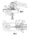
- FIG. 1 is a perspective view of a tool holder in accordance with the present invention.
- FIG. 2 is a perspective view with the holder in an unlocked position.
- FIG. 3 is a side elevation view of the holder of FIG. 1.
- FIG. 4 is a top plan view of the holder of FIG. 1.
- FIG. 5 is an enlarged side view like FIG. 3.
- FIG. 6 is an enlarged perspective view of the locking mechanism of FIG. 4.
- FIG. 7 is a perspective view of a second embodiment in accordance with the present invention
- FIG. 7A is an enlarged perspective view of the locking mechanism of FIG. 7.
- The following description of the preferred embodiment(s) is merely exemplary in nature and is in no way intended to limit the invention, its application, or uses.
- Turning to the figures, a tool holder is illustrated and designated with the
reference numeral 10. The tool holder is a table mount to hold battery poweredscissors 12. Thescissors 12 include ahousing 14 which includes acutting nib 16 at one end of the housing. The scissors include atrigger switch 18 and a sliding switch 20 to activate the scissors. The sliding switch 20 must be in an on position in order for thetrigger switch 18 to activate thecutting nibs 16, or vice versa. Also, the outer surface of thehousing 14 includesrecesses 22 which provide an aesthetic appearance and enhance gripping of thescissors 12 when positioned in theholder 10. - The
holder 10 includes a base 30 with aclamp mechanism 32 which retains theholder 10 on a surface. Also, aholder 34 is coupled with thebase 30. The clampingmember 32 includes an L-shapedmember 36 having a first leg 38 attached to thebase 30 and a second leg 40 substantially perpendicular to the first leg 38. A thumbscrew 42 is positioned through the leg 40. The thumbscrew 42 is rotated to secure thetool holder 10 onto a surface. - The
base 30 is generally a planar member. Thebase 30 has a desired configuration and is illustrated as an ellipis or oval. Ordinarily, thebase 30 includes a plurality ofapertures 44 which form perforations in thebase 30. Theperforations 44 enable sound to pass through the base 30 so that sound is not reflected back to the user which, in turn, reduces noise during operation. - The
base 30 includes aholder support 46. Theholder support 46 extends perpendicular from thebase 30. Thesupport 46 has a desired height so that, when thescissors 12 are positioned in the holder (see FIG. 3), thenibs 16 of thescissors 12 are positioned and spaced above the base. The positioning of thenibs 16 above thebase 30 reduces rattle and noise. Thesupport 46 includes a plurality ofapertures 48. The apertures enhance the strength as well as reduce the noise during operation of the scissors. - The
tool holder 34 includes a pair ofmembers members support 46 via apivot arrangement 54. Thus, themembers scissors 12 to be positioned between and retained by themembers - The
members bore 56 which extends through the twomembers bore 56 receives thescissors 12. Themembers cutout 58 which enables the second scissor switch 20 to project between the twomembers - The
members locking mechanism 60. Thelocking mechanism 60 includes alatch 62 slidably received onrails rail 64, onmember 50, fits incutout portion 68 ofrail 66. Thus, when thelatch 62 is in a locked position, covering therails members latch 62 is moved in onedirection uncovering rail 64 which enablesmember 50 to pivot with respect tomember 52. This enables thescissors 12 to be removed from themembers - The inner surface of the
members contour 70 which fits into therecess 22 on thescissors 12. Thecontour 70 retains thescissors 12 in position in theholder 34 when thescissors 12 are locked between themembers - The
members switch activating mechanism 72. The triggerswitch activating mechanism 72 includes a configuration to receive thetrigger switch 18. Aramp 74 is positioned on the inner surface of thetrigger activation mechanism 72. Theramp 74 contacts thetrigger 18 forcing it into an on position. Accordingly, when thescissors 12 are locked into theholder 34, thetrigger switch 18 is in an on position. When the sliding switch 20 is moved to an on position, the scissors are activated. At this time, the scissors are securely locked into theholder 34 and thescissors 12 are in the on position. Accordingly, the user has both hands free from thescissors 12 to enable "hands free" use of thescissors 12. - The tool holder may be manufactured from an injection molding operation. In this case, several of the elements, such as the
base 30, theclamping mechanism 32,support 46 and possibly part of theholder 34 may be manufactured as a single plastic piece. Themember 50 would then be secured along thepivot mechanism 54 and thelock latch 62 installed onto therails - Turning to FIGS. 7 and 7A, a second embodiment is illustrated. In FIGS. 5 and 5A, the elements which are the same will be identified with the same reference numerals. Here, the difference resides in the
locking mechanism 160. Themembers latch 162 and catch 164 mechanism. As themembers latch 162 with a dependingtang 166 is secured in thecatch 164. To release thelatch 162 from thecatch 164, thelatch 162 is lifted up and themembers holder mechanism 34 is substantially identical to that which has been previously described. - While the above detailed description provides a description of the preferred embodiment, other objects and advantages of the present invention will become apparent to those skilled in the art.
Claims (20)
- A tool holder comprising:a base;a mechanism coupled with said base for securing said base to a surface;a holder coupled with said base, said holder having a wall defining a bore to receive the tool; anda mechanism coupled with said wall for activating a switch on the tool.
- The tool holder according to Claim 1, wherein said holder being spaced with respect to said base so that the tool, when in said holder, is spaced from the base.
- The tool holder according to Claim 1, wherein said base being perforated for reducing noise.
- The tool holder according to Claim 1, wherein said wall includes a cutout for enabling access to a second switch on the tool.
- The tool holder according to Claim 1, wherein said wall has an inner surface having a design to complement an outer surface of the tool for enhancing retention of the tool in the wall.
- A tool holder comprising:a base;a mechanism coupled with said base for securing said base to a surface;a holder coupled with said base, said holder including a pair of members pivotable with respect to one another between an open and a closed position for receiving and releasing a tool; anda locking mechanism for locking said pair of members with respect to one another to lock the tool between the members.
- The tool holder according to Claim 6, further comprising at least one of said pair of members including a mechanism for activating a switch on the tool.
- The tool holder according to Claim 6, wherein said pair of members include an inner surface having a design complementing an outer surface of the tool for enhancing retention of the tool in the holder.
- The tool holder according to Claim 6, wherein said holder being spaced with respect to said base so that the tool, when in said holder, is spaced from the base.
- The tool holder according to Claim 6, wherein said base being perforated for reducing noise.
- The tool holder according to Claim 6, wherein said pair of members includes a cutout for enabling access to a second switch on the tool.
- The tool holder according to Claim 6, wherein said lock mechanism includes a rail on each member and a latch coupled with said rails for slidably engaging said rails for locking the member with one another.
- The tool holder according to Claim 6, wherein said locking mechanism includes a latch and a catch on said pair of members for locking the member with one another.
- A scissor holder comprising:a base;a mechanism coupled with said base for securing said base to a surface;a holder coupled with said base, said holder including a pair of members pivotable with respect to one another between an open and a closed position for receiving and releasing scissors; anda locking mechanism for locking said pair of members with respect to one another to lock the scissors between the members.
- The scissor holder according to Claim 14, further comprising at least one of said pair of members including a mechanism for activating a switch on the scissors.
- The scissor holder according to Claim 14, wherein said pair of members include an inner surface having a design complementing an outer surface of the scissors for enhancing retention of the scissors in the holder.
- The scissor holder according to Claim 14, wherein said holder being spaced with respect to said base so that the scissors, when in said holder, are spaced from the base.
- The scissor holder according to Claim 14, wherein said base being perforated for reducing noise.
- The scissor holder according to Claim 14, wherein said pair of members includes a cutout for enabling access to a second switch on the scissors.
- The scissor holder according to Claim 14, wherein said lock mechanism includes a rail on each member and a latch coupled with said rails for slidably engaging said rails for locking said members to one another.
Applications Claiming Priority (1)
| Application Number | Priority Date | Filing Date | Title |
|---|---|---|---|
| US11/185,903 US20070017103A1 (en) | 2005-07-20 | 2005-07-20 | Table mount holder for battery powered scissors |
Publications (1)
| Publication Number | Publication Date |
|---|---|
| EP1745894A2 true EP1745894A2 (en) | 2007-01-24 |
Family
ID=37116058
Family Applications (1)
| Application Number | Title | Priority Date | Filing Date |
|---|---|---|---|
| EP06117469A Withdrawn EP1745894A2 (en) | 2005-07-20 | 2006-07-19 | Table mount holder for tool |
Country Status (5)
| Country | Link |
|---|---|
| US (1) | US20070017103A1 (en) |
| EP (1) | EP1745894A2 (en) |
| CN (1) | CN1915608A (en) |
| AU (1) | AU2006203056A1 (en) |
| NZ (2) | NZ555883A (en) |
Families Citing this family (1)
| Publication number | Priority date | Publication date | Assignee | Title |
|---|---|---|---|---|
| USD567618S1 (en) * | 2005-07-20 | 2008-04-29 | Black & Decker Inc. | Tool support |
Citations (3)
| Publication number | Priority date | Publication date | Assignee | Title |
|---|---|---|---|---|
| US2316486A (en) | 1942-04-18 | 1943-04-13 | Singer Mfg Co | Supporting base for electric scissors |
| US2324364A (en) | 1942-02-09 | 1943-07-13 | Singer Mfg Co | Supporting base for electric scissors |
| US3698087A (en) | 1971-04-05 | 1972-10-17 | Singer Co | Pedestal for electric scissors |
Family Cites Families (45)
| Publication number | Priority date | Publication date | Assignee | Title |
|---|---|---|---|---|
| US273857A (en) * | 1883-03-13 | Lamp holder and bracket | ||
| US1232690A (en) * | 1914-07-27 | 1917-07-10 | Peter D Keenan | Nursing-bottle bracket. |
| US1295101A (en) * | 1918-04-01 | 1919-02-25 | Harry Craig Bellows | Stitch-cutter. |
| US1554118A (en) * | 1921-03-28 | 1925-09-15 | Moran William | Bottle holder |
| US1707754A (en) * | 1927-10-12 | 1929-04-02 | Bone Charles Harold | Clamp |
| US1802571A (en) * | 1928-02-06 | 1931-04-28 | Orussa Lorence | Electric scissors |
| US1939833A (en) * | 1932-05-05 | 1933-12-19 | Schwartz Mendel | Garment bottom cutter |
| US1996813A (en) * | 1932-10-24 | 1935-04-09 | Chicago Flexible Shaft Co | Electric scissors |
| US2047483A (en) * | 1934-11-14 | 1936-07-14 | Chicago Flexible Shaft Co | Scissors and the like |
| US2635335A (en) * | 1949-04-04 | 1953-04-21 | Robert W James | Power-driven hand sheet metal shears |
| US2522255A (en) * | 1949-06-18 | 1950-09-12 | Climo Samuel | Fishing rod holder |
| US2814455A (en) * | 1954-02-04 | 1957-11-26 | Woodrow W Rainey | Pressing iron clamp |
| US2942340A (en) * | 1956-12-10 | 1960-06-28 | Brown Arthur William | Means for adjusting the level of a hem of the skirt of a garment |
| US2914829A (en) * | 1957-04-10 | 1959-12-01 | Louis F Willemain | Grass catcher clamping device |
| US2887287A (en) * | 1957-05-14 | 1959-05-19 | Elmer H Ross | Fishing pole holder |
| US3365963A (en) * | 1965-07-19 | 1968-01-30 | Singer Co | Battery powered scissors |
| US3421218A (en) * | 1966-08-01 | 1969-01-14 | Richard A Thompson | Electric scissors |
| US3478426A (en) * | 1967-06-22 | 1969-11-18 | Name Maker Corp | Electric scissors |
| US3474534A (en) * | 1967-07-05 | 1969-10-28 | Arvin Ind Inc | Scissors blades |
| CH511100A (en) * | 1969-04-25 | 1971-08-15 | Styner & Bienz Ag | Electric shear device |
| US3698086A (en) * | 1970-07-01 | 1972-10-17 | Singer Co | Electric scissors |
| US3676928A (en) * | 1970-07-01 | 1972-07-18 | Singer Co | Electric scissors |
| US3710445A (en) * | 1971-02-12 | 1973-01-16 | H Roth | A cutter device with illuminated cutting blade |
| US3792829A (en) * | 1971-10-26 | 1974-02-19 | L Fickett | Fishing rod holder |
| US4050003A (en) * | 1974-08-23 | 1977-09-20 | The Black And Decker Manufacturing Company | Modular cordless tools |
| US3952239A (en) * | 1974-08-23 | 1976-04-20 | The Black And Decker Manufacturing Company | Modular cordless tools |
| US3973179A (en) * | 1974-08-23 | 1976-08-03 | The Black And Decker Manufacturing Company | Modular cordless tools |
| DE3507125C1 (en) * | 1985-02-28 | 1986-01-02 | Elias 8034 Germering Lebessis | Device for re-cutting, cutting and cutting wallpaper |
| USD346221S (en) * | 1991-12-23 | 1994-04-19 | Godfrey Dennis H | Holder for a nursing bottle |
| US5261430A (en) * | 1992-03-02 | 1993-11-16 | Mochel David J | System of oral hygiene and personal care apparatus with interchangeable and replaceable elements |
| US5353504A (en) * | 1993-04-30 | 1994-10-11 | Pai Chung Jen | Motorized scissors |
| US5775654A (en) * | 1996-07-15 | 1998-07-07 | Price; Betty J. | Telescoping cup holding system |
| GB9718305D0 (en) * | 1997-08-30 | 1997-11-05 | Black & Decker Inc | Power tool |
| GB9718312D0 (en) * | 1997-08-30 | 1997-11-05 | Black & Decker Inc | Power tool |
| GB9718336D0 (en) * | 1997-08-30 | 1997-11-05 | Black & Decker Inc | Power tool |
| DE19756766A1 (en) * | 1997-12-19 | 1999-06-24 | Bosch Gmbh Robert | Portable electric saw with interchangeable tool holder |
| GB9804472D0 (en) * | 1998-03-04 | 1998-04-29 | Black & Decker Inc | A switch lock-off mechanism |
| US6181032B1 (en) * | 1999-07-14 | 2001-01-30 | Black & Decker Inc. | Releasably connecting power packs to electrical appliances |
| GB0005821D0 (en) * | 2000-03-10 | 2000-05-03 | Black & Decker Inc | Coupling method |
| GB0005937D0 (en) * | 2000-03-10 | 2000-05-03 | Black & Decker Inc | Interlock mechanism |
| US6375132B1 (en) * | 2000-08-11 | 2002-04-23 | Elaine N. Tomlinson | Electric iron safety stand |
| US6588108B2 (en) * | 2001-04-27 | 2003-07-08 | Victor C. Talavera | Hair trimming device with removably mountable components for removal of split ends and styling of hair |
| US6675483B2 (en) * | 2001-11-29 | 2004-01-13 | Helman Group, Ltd. | Combination barbecue tool |
| USD496572S1 (en) * | 2003-09-26 | 2004-09-28 | Innodesk Home, Inc. | Powered scissors |
| US7178777B1 (en) * | 2004-03-02 | 2007-02-20 | Banker Bret H | Adjustable tension clip and method of use |
-
2005
- 2005-07-20 US US11/185,903 patent/US20070017103A1/en not_active Abandoned
-
2006
- 2006-07-18 AU AU2006203056A patent/AU2006203056A1/en not_active Abandoned
- 2006-07-19 NZ NZ555883A patent/NZ555883A/en not_active IP Right Cessation
- 2006-07-19 NZ NZ548610A patent/NZ548610A/en not_active IP Right Cessation
- 2006-07-19 EP EP06117469A patent/EP1745894A2/en not_active Withdrawn
- 2006-07-20 CN CNA2006101357562A patent/CN1915608A/en active Pending
Patent Citations (3)
| Publication number | Priority date | Publication date | Assignee | Title |
|---|---|---|---|---|
| US2324364A (en) | 1942-02-09 | 1943-07-13 | Singer Mfg Co | Supporting base for electric scissors |
| US2316486A (en) | 1942-04-18 | 1943-04-13 | Singer Mfg Co | Supporting base for electric scissors |
| US3698087A (en) | 1971-04-05 | 1972-10-17 | Singer Co | Pedestal for electric scissors |
Also Published As
| Publication number | Publication date |
|---|---|
| US20070017103A1 (en) | 2007-01-25 |
| NZ548610A (en) | 2007-11-30 |
| AU2006203056A1 (en) | 2007-02-08 |
| NZ555883A (en) | 2009-02-28 |
| CN1915608A (en) | 2007-02-21 |
Similar Documents
| Publication | Publication Date | Title |
|---|---|---|
| US11724408B2 (en) | Utility knife | |
| US9492931B2 (en) | Utility knife | |
| US7340836B2 (en) | Hand tool for measuring and cutting | |
| EP1197393B1 (en) | Automobile molding and fastener therefor | |
| US6322126B1 (en) | Visor support apparatus | |
| US20050093304A1 (en) | Locking device with releasable latching means | |
| US20060150423A1 (en) | Adjustable blade utility knife | |
| US20110061506A1 (en) | Guard system for a power saw | |
| US8065803B2 (en) | Cutting tool | |
| JPH11510742A (en) | Pocket knife type handheld universal collecting device | |
| US8006388B1 (en) | Combination retractable knife and saw utility tool | |
| GB2466372A (en) | Security device preventing unauthorised removal of knives from a storage block | |
| US20050060896A1 (en) | Clamping apparatus for a tool component and an improved scrolling mechanism | |
| JP2012140116A (en) | Seat slide device | |
| KR20050021232A (en) | Load floor latch | |
| KR0130495Y1 (en) | Latch device | |
| US7165334B2 (en) | Guide clamp | |
| US7182055B1 (en) | Remote car starter shielding apparatus | |
| US20070017103A1 (en) | Table mount holder for battery powered scissors | |
| JPS62500227A (en) | Combination device used to staple and perforate sheets of paper | |
| JP4394052B2 (en) | Binding tool | |
| WO2008016720A2 (en) | Utility knife | |
| GB2332470A (en) | Latch member restraint | |
| KR200239178Y1 (en) | A lock for furniture | |
| JPH04341898A (en) | Binder |
Legal Events
| Date | Code | Title | Description |
|---|---|---|---|
| PUAI | Public reference made under article 153(3) epc to a published international application that has entered the european phase |
Free format text: ORIGINAL CODE: 0009012 |
|
| AK | Designated contracting states |
Kind code of ref document: A2 Designated state(s): AT BE BG CH CY CZ DE DK EE ES FI FR GB GR HU IE IS IT LI LT LU LV MC NL PL PT RO SE SI SK TR |
|
| AX | Request for extension of the european patent |
Extension state: AL BA HR MK YU |
|
| STAA | Information on the status of an ep patent application or granted ep patent |
Free format text: STATUS: THE APPLICATION IS DEEMED TO BE WITHDRAWN |
|
| 18D | Application deemed to be withdrawn |
Effective date: 20100202 |