EP1745547B1 - Capacitance activated switch device - Google Patents
Capacitance activated switch device Download PDFInfo
- Publication number
- EP1745547B1 EP1745547B1 EP05735312A EP05735312A EP1745547B1 EP 1745547 B1 EP1745547 B1 EP 1745547B1 EP 05735312 A EP05735312 A EP 05735312A EP 05735312 A EP05735312 A EP 05735312A EP 1745547 B1 EP1745547 B1 EP 1745547B1
- Authority
- EP
- European Patent Office
- Prior art keywords
- capacitance
- switch device
- activated switch
- voltage
- door
- Prior art date
- Legal status (The legal status is an assumption and is not a legal conclusion. Google has not performed a legal analysis and makes no representation as to the accuracy of the status listed.)
- Expired - Lifetime
Links
- 230000005684 electric field Effects 0.000 claims abstract description 32
- 239000004020 conductor Substances 0.000 claims abstract description 27
- 230000008859 change Effects 0.000 claims abstract description 15
- 230000003213 activating effect Effects 0.000 claims abstract description 8
- 230000033001 locomotion Effects 0.000 claims description 15
- 239000003990 capacitor Substances 0.000 claims description 10
- 239000012811 non-conductive material Substances 0.000 claims description 5
- 230000005540 biological transmission Effects 0.000 claims 1
- 238000001514 detection method Methods 0.000 description 12
- 229920001971 elastomer Polymers 0.000 description 8
- 238000000034 method Methods 0.000 description 6
- 238000003384 imaging method Methods 0.000 description 5
- 230000007423 decrease Effects 0.000 description 4
- 239000011521 glass Substances 0.000 description 4
- 230000008901 benefit Effects 0.000 description 3
- 230000007613 environmental effect Effects 0.000 description 3
- 238000004519 manufacturing process Methods 0.000 description 3
- 239000000806 elastomer Substances 0.000 description 2
- 239000005357 flat glass Substances 0.000 description 2
- 238000009434 installation Methods 0.000 description 2
- 239000012212 insulator Substances 0.000 description 2
- 230000001681 protective effect Effects 0.000 description 2
- 239000004065 semiconductor Substances 0.000 description 2
- RYGMFSIKBFXOCR-UHFFFAOYSA-N Copper Chemical compound [Cu] RYGMFSIKBFXOCR-UHFFFAOYSA-N 0.000 description 1
- 229910000831 Steel Inorganic materials 0.000 description 1
- 208000027418 Wounds and injury Diseases 0.000 description 1
- 230000004913 activation Effects 0.000 description 1
- 239000000853 adhesive Substances 0.000 description 1
- 230000001070 adhesive effect Effects 0.000 description 1
- XAGFODPZIPBFFR-UHFFFAOYSA-N aluminium Chemical compound [Al] XAGFODPZIPBFFR-UHFFFAOYSA-N 0.000 description 1
- 229910052782 aluminium Inorganic materials 0.000 description 1
- 238000005219 brazing Methods 0.000 description 1
- 239000011248 coating agent Substances 0.000 description 1
- 238000000576 coating method Methods 0.000 description 1
- 230000006835 compression Effects 0.000 description 1
- 238000007906 compression Methods 0.000 description 1
- 239000011889 copper foil Substances 0.000 description 1
- 230000008878 coupling Effects 0.000 description 1
- 238000010168 coupling process Methods 0.000 description 1
- 238000005859 coupling reaction Methods 0.000 description 1
- 230000006378 damage Effects 0.000 description 1
- 238000010586 diagram Methods 0.000 description 1
- 238000006073 displacement reaction Methods 0.000 description 1
- 230000009977 dual effect Effects 0.000 description 1
- 239000000428 dust Substances 0.000 description 1
- 230000000694 effects Effects 0.000 description 1
- 239000013536 elastomeric material Substances 0.000 description 1
- 208000014674 injury Diseases 0.000 description 1
- 239000000463 material Substances 0.000 description 1
- 238000005259 measurement Methods 0.000 description 1
- 230000007246 mechanism Effects 0.000 description 1
- 239000007769 metal material Substances 0.000 description 1
- 229920000642 polymer Polymers 0.000 description 1
- 239000002861 polymer material Substances 0.000 description 1
- 230000009467 reduction Effects 0.000 description 1
- 230000035945 sensitivity Effects 0.000 description 1
- 230000008054 signal transmission Effects 0.000 description 1
- 230000011664 signaling Effects 0.000 description 1
- 238000005476 soldering Methods 0.000 description 1
- 125000006850 spacer group Chemical group 0.000 description 1
- 239000010959 steel Substances 0.000 description 1
- 238000006467 substitution reaction Methods 0.000 description 1
- 230000000007 visual effect Effects 0.000 description 1
Images

Classifications
-
- H—ELECTRICITY
- H03—ELECTRONIC CIRCUITRY
- H03K—PULSE TECHNIQUE
- H03K17/00—Electronic switching or gating, i.e. not by contact-making and –breaking
- H03K17/94—Electronic switching or gating, i.e. not by contact-making and –breaking characterised by the way in which the control signals are generated
- H03K17/96—Touch switches
- H03K17/962—Capacitive touch switches
-
- H—ELECTRICITY
- H03—ELECTRONIC CIRCUITRY
- H03K—PULSE TECHNIQUE
- H03K17/00—Electronic switching or gating, i.e. not by contact-making and –breaking
- H03K17/94—Electronic switching or gating, i.e. not by contact-making and –breaking characterised by the way in which the control signals are generated
- H03K17/945—Proximity switches
- H03K17/955—Proximity switches using a capacitive detector
-
- H—ELECTRICITY
- H03—ELECTRONIC CIRCUITRY
- H03K—PULSE TECHNIQUE
- H03K2217/00—Indexing scheme related to electronic switching or gating, i.e. not by contact-making or -breaking covered by H03K17/00
- H03K2217/94—Indexing scheme related to electronic switching or gating, i.e. not by contact-making or -breaking covered by H03K17/00 characterised by the way in which the control signal is generated
- H03K2217/96—Touch switches
- H03K2217/9607—Capacitive touch switches
- H03K2217/960755—Constructional details of capacitive touch and proximity switches
Definitions
- the present invention relates, in general, to a switch device and, more particularly, the instant invention relates to a switch device operable by a capacitive load and, still more particularly, the instant invention relates to a capacitance activated switch device for use in a transit vehicle.
- the passenger may pay only upon entering the vehicle through only one side door located next to a vehicle operator while the other side doors are used predominantly for passenger egress.
- partially operating side door systems decreases component wear and increases durability and reliability of such side door systems. Therefore, in such applications, it is common for a vehicle operator to selectively open certain side doors while placing other side doors in a condition enabling the passenger to open such side doors by contacting a switch devices mounted either directly on the side door or in its vicinity.
- United States Patent No 5,118,910 entitled “Illuminated, pressure-actuated switch” teaches a press-at-any-point tape switch suitable for opening doors of a transit vehicle.
- the switch includes a pair of electrodes which are spaced in a steady state nonactivated condition and which produce an electrical signal upon pressure being applied to an exterior surface of the tape switch. The resulting electrical signal is used by the door drive and door controller to open the door which then enables passenger egress.
- a door system of the transit vehicle must incorporate an obstruction detection capability during the closing cycle in order to detect a passenger or an object present in the path of the closing door.
- the obstruction detection is accomplished by four different methods.
- a sensitive rubber edge is employed at the leading edge of the door in combination with a pressure wave switch having an electrical connection with the door controller.
- the sensitivity of the rubber edge is achieved by incorporating a sealed chamber with a connection of a predetermined orifice to the pressure wave switch. The passenger or object contacting the rubber edge during the door closing cycle will deform the rubber edge thus causing the pressure differential within the seal chamber to change the state of the pressure wave switch and prevent further door closing via the door controller either terminating the closing motion or reversing the motion of the door in the opening direction.
- a variation of such obstruction detection method is associated with use of an electrical tape type switch inserted into a chamber and having an electrical connection with the door controller, whereby the oppositely disposed contacts of the switch engage one another upon deformation of the rubber edge.
- a microprocessor based door controller executes a software algorithm during door closing motion and monitors and compares parameters such as electrical current, position versus time, and others, against a predetermined threshold. The passenger or object contacting the door during the closing cycle will cause such parameters to differ from the threshold, for example the electrical current will increase, enabling the door controller to prevent further door closing.
- the obstruction detection may be enabled by the door controller if the door did not reach a final closing position within a predetermined time period.
- the obstruction detection method employs a sensor centrally installed above the door opening and having an electrical connection with the door controller. Presence of the passenger or object will be detected by the sensor enabling the door controller to prevent further door closing.
- the main disadvantage of the first three methods is that obstruction detection is enabled only upon physical contact with the passenger or object which is not desirable when such passenger is a small child or an adult with limited physical capabilities as the contact with the moving door may result in some form of injury.
- Utilization of remote sensors in the fourth method eliminates physical contact but is generally costly to implement and is subject to precise tuning in order to properly define coverage area and minimize external noise.
- obstruction detection that substantially minimizes or eliminates physical contact between the passenger or object and closing door and reduces installation costs.
- WO96/36134 discloses a system for non-contact sensing and signaling using human body as signal transmission medium.
- the system has a transmitter and a receiver that are coupled through a user and ground.
- the transmitter generates a low-frequency signal that, through capacitive coupling, passes as displacement currents into and from the body of the user.
- the receiver has several electrodes and a detection circuit arranged such as to detect motion of the body.
- the present invention overcomes the disadvantages of the presently used switch devices for opening doors by employing an electric field imaging device electrically coupled via an electrical antenna conductor to a conductive electrode member that is attached to the door or any other suitable surfaces with the use of electrical isolating spacers.
- Such electric field imaging device generates a sine wave of a predetermined frequency, which is transmitted to the electrode member thus producing a surrounding electrical field.
- a resistor of a predetermined value is electrically coupled intermediate the wave generator and the conductive electrode member. Any body part, such as hand, arm, shoulder, or torso, which enters such electrical field, will create a capacitive load due to the body being grounded to a floor surface.
- Reduction in distance between the body part and the conductive electrode will increase the capacitance and will decrease the voltage intermediate the resistor and conductive electrode which is an inverse function of the capacitance.
- Such change in voltage will be detected by a combination of the electric field imaging device and a microcontroller coupled thereto by comparing voltages at each end of the resistor and the change exceeding a predetermined threshold will be associated with an output signal.
- Such output signal when received by a door controller, will be interpreted thereby as a request to open the door enabling a door drive connected to the door to move thereof in an opening direction.
- the opening of the door will not require the passenger to apply pressure.
- the electric field imaging device and the microcontroller may be mounted to a printed circuit board that can be disposed within a housing of the touch bar, in the space occupied by the electro-mechanical switch or may be adapted with its own housing and disposed adjacent the conductive electrode member in a touch tape switch configuration.
- the door itself manufactured form conductive material may be used as a switch device or the electrical antenna conductor may be imbedded in a glass portion of the door thus enabling the passenger to open the door by approaching such glass portion.
- the present invention overcomes the disadvantages of the presently used switch devices for obstruction detection by employing the electrical antenna conductor disposed within the door edge, in a through aperture generally extruded therein.
- the passenger or an object present in the path of the closing door will create the capacitive load when entering the electrical field formed by the electrical antenna conductor thus enabling the door controller to either discontinue or reverse closing motion of the door.
- the door itself manufactured from conductive material and coupled to the electrical antenna conductor may be employed for obstruction detection.
- a capacitance activated switch device, generally designated 40 is best illustrated in FIG. 2 .
- Such capacitance activated switch device 40 comprises a capacitance means, generally designated 41, having a generator 42 capable of generating a sine wave 44 of a predetermined frequency 46.
- the capacitance means 41 is grounded at a first ground means 48 and is adapted to at least receive an operating voltage 97 associated with an input voltage V INPUT .
- a first resistor 50 of a first predetermined resistive value is internally coupled to the generator 42 at a first end 72 and is externally coupled to at least one electrical antenna output 49 at a second end 73. In operation, such first resistor 50 will enable a first voltage V 1 at a first end 72 and a second voltage V 2 at a second end 73.
- the capacitance means 41 is adapted for providing at least one first digital signal 74, preferably being a plurality of first digital signals 74, and at least one analog output signal 76 to microcontroller 78 capable of executing a predetermined software algorithm.
- the capacitance means 41 is further adapted for receiving at least one second digital signal 75, preferably being a plurality of second digital signals 75, from the microcontroller 78.
- such capacitance means 41 is an electric field imaging device model MC 33794 manufactured by MOTOROLA and/or its spin-off, Freescale Semiconductor, Inc.
- the at least one electrical antenna conductor 52 is electrically coupled to the at least one electrical antenna output 49 at one end and to a conductive electrode means 54 at a distal end.
- the conductive electrode means 54 is rigidly attached to a mounting member 56.
- At least one electrical isolator means 58 may be provided in application where such member 56 does not inherently contain dielectric capabilities.
- a means 60 representing an object or human body part is coupled to the third ground means 62, generally being the floor portion 18.
- the generator 42 will generate the sine wave 44 which will be transmitted to the conductive electrode means 54 by the at least one electrical antenna conductor 52 enabling generation of an electrical field 64 having a predetermined depth and at least partially surrounding the conductive electrode means 54.
- Any grounded object or human body part 60 grounded to the third grounding means 62 and entering the electrical field 64 will produce a capacitive load 66.
- Such capacitive load 66 will result in second voltage V 2 being smaller than the first voltage V 1 .
- Continuing movement of the object 60 toward the conductive electrode means 54 will incrementally increase such capacitive load 66 and therefore incrementally decrease the second voltage V 2 .
- the maximum capacitance value will be achieved upon contact of such object 60 with the conductive electrode means 54.
- the change in the second voltage V 2 will be detected by the microcontroller 78 via at least one analog input 76 and the change exceeding a predetermined voltage threshold in the software algorithm will trigger an output signal 80 generating at least one control signal 92 to the door controller which is not shown but is well known in the art.
- an output driver 90 is disposed intermediate the output signal 80 and the at least one control signal 92 to receive such output signal 80 and generate the at least one control signal 92 being a voltage signal and further being equal to the input voltage V INPUT .
- the software algorithm is capable of differentiating between a gradual movement of the means 60 within the electrical field 64 as such gradual movement will result in a gradual change of the second voltage V 2 over a first predetermined period of time and an impact between the means 60 and the conductive electrode means 54 which will result in change of the second voltage V 2 over a second predetermined period of time being substantially smaller than such first predetermined period of time.
- the capacitance activated switch device 40 may be adapted with a second resistor 86 having a second predetermined resistive value which is electrically coupled to the capacitance means 41 via an electrical path 87 for adjusting the predetermined frequency 46 and, more importantly, for adjusting a predetermined depth of the electrical field 64.
- the capacitance activated switch device 40 may further include a first capacitor 82 having a first predetermined capacitance value generally defining a lower capacitance limit and second capacitor 84 having a second predetermined capacitance value generally defining an upper capacitance limit. It will be appreciated that such first capacitor 82 will generate a first voltage reference 83 defining a predetermined upper limit of the expected voltage from the electrical field 64 and such second capacitor 84 will generate a second voltage reference 85 defining a predetermined lower limit of the expected voltage from the electrical field 64. In a first aspect, such first and second voltage references 83 and 85 respectively may be used by the microcontroller 78 to measure actual capacitance value of the capacitive load 66.
- the first voltage reference 83 may be used by the microcontroller 78 to identify a broken electrical connection coupled to the capacitance means 41.
- the microcontroller 78 can compensate for environmental temperature or input voltage V INPUT variations by continuously measuring the first and second voltage references 83 and 85 respectively, by continuously comparing actual measurements against their predetermined default values and storing the last calculated difference. In operation, such last calculated difference will be used by the microcontroller 78 to proportionally adjust the measured second voltage V 2 via the software algorithm.
- the capacitance activated switch device 40 may additionally include a means 96, such as a well known voltage regulator 96, for converting input voltage V INPUT into the operating voltage 97.
- means 96 may be also an internal power source such as battery for supplying such operating voltage 97.
- the capacitance means 41, the microcontroller 78, the output driver 90, the first and second capacitors 82 and 84 respectively, the second resistor 86, and the means 96 are mounted to a printed circuit board 98 by one of through hole and surface mount methods.
- such components may be disposed within the door controller (not shown).
- FIG. 1 illustrating a portion of a transit vehicle, generally designated 10, having a floor member 12 and a wall member 14.
- a door 30 is disposed within a wall aperture 16 and is driven by a door drive 34 in one of closing and opening directions to at least partially cover and uncover such aperture 16.
- the door 30 is supported by a door support means 32 which may be integral to door drive 34.
- a floor portion 18 disposed adjacent the door 30 may be constructed as a planar inclined surface or constructed as a stairwell which is not shown but is well known in the art.
- a traction member 19 manufactured from elastomeric or polymer material is applied to a surface of such floor member 12 and floor portion 18.
- the traction member 19 may be a well known sensitive treadle mat.
- such floor portion 18 may incorporate a movable accessibility device (not shown), such as taught by U.S. Patent 5,775,232 , which extends outwardly from the wall member 14 to accommodate ingress and egress of passengers with disabilities or needing further assistance.
- a movable accessibility device such as taught by U.S. Patent 5,775,232 , which extends outwardly from the wall member 14 to accommodate ingress and egress of passengers with disabilities or needing further assistance.
- U.S. Patent 5,775,232 is hereby incorporated by reference thereto.
- a screen member 20 may be provided within the transit vehicle 10 for separating a seating area 22 from the standing area defined by the door 30 and floor portion 18.
- a second door 36 supported by a door support means 38 may be disposed within the wall aperture 16 adjacent the first door 30. In such arrangement, the first door 30 and the second door 36 move in opposite directions for covering and uncovering the wall aperture 16.
- touch bar 100 The structure and operation of the capacitance activated switch device 40 of the first embodiment is illustrated in a combination with an activating member such as touch bar, generally designated 100, which is rigidly attached to at least door 30 adjacent its leading edge 31.
- touch bar 100 comprises a tubular member 102 having a wall 104 and being disposed between an upper housing 110 and a lower housing 120 which are rigidly attached to the surface of the door 30.
- the upper housing 110 is adapted with a first cavity 112 for attachment to an end of the tubular member 102, a first aperture 114 and a second aperture 116 which is aligned with an aperture 33 disposed within the door 30.
- the first cavity 112 may be provided with an annular grove 117 for housing a resilient member 118 surrounding the tubular member 102.
- the first aperture 114 is fitted with an end plug 122.
- the lower housing 120 is constructed generally similar to the upper housing except that it does not contain an aperture 116 and is further provided with the cover member 124.
- the upper and lower housings 110 and 120 respectively are manufactured from electrically non-conductive materials enabling direct attachment to the door 30. It will be appreciated that a metallic electrically conductive substitution may be readily made with an employment of at least one electrical isolator 126 disposed intermediate such housings and the door 30.
- capacitance activated switch device 40 is secured within the first aperture 114, preferably by the end plug 122.
- the at least one electrical antenna conductor 52 is electrically and rigidly attached to either interior or exterior surfaces of the wall 104 by any well known methods including but not limited to such methods as soldering, brazing or mechanical fastening.
- the at least one electrical antenna conductor 52 may include a rigid antenna portion 52a longitudinally disposed within the tubular member 102.
- the supply voltage V INPUT and the at least one control signal 92 are provided via a wire bundle 130 routed through the second aperture 116 and the door aperture 33 to the door controller (not shown).
- presence of the supply voltage V INPUT will generate an electrical field 64 at least partially surrounding the tubular member 102.
- the passenger approaching the tubular member 102 with any body part, such as hand, arm, shoulder, or torso will create a capacitive load 66 upon entering such at least partially surrounding electric field 64 causing the value of the second voltage V 2 to change.
- Such change in the second voltage V 2 will be detected by the capacitance means 41 and the microcontroller 78 and followed by generation of the output signal 80 and subsequently followed by generation of at least one control signal 92 which will be interpreted by the door controller (not shown) as a request to open or reopen the door 30 enabling the door drive 34 to move the door 30 in an opening direction.
- the at least one control signal 92 may be further used to energize visual indicators (not shown) disposed above the door 30 or enable other annunciation or control functions.
- a capacitor is defined as a pair of electrical conductors separated by a space, any coating or non conductive material encasing such tubular member 102 will not disrupt operation of the capacitance activated switch device 40.
- the capacitance activated switch device 40 may be mounted remotely, as best illustrated by reference 99 in FIG. 1 . It will be appreciated that in such installation, the capacitance activated switch device 40 will be disposed within a housing 91 and the wire bundle 130 will be routed through the vehicle structure, the door 30 and the upper housing 110 and such wire bundle 130 will further contain the at least one electrical conductor 52. Preferably, such at least one electrical antenna conductor 52 will be shielded and having a shield conductor 164 coupled to a shield output 51 of the capacitance activated switch device 40.
- the structure of the capacitance activated switch device 40 of another embodiment is illustrated in a combination with a touch switch type, generally designated 150, which may be rigidly attached to the door 30 at inner and outer surface thereof, wind screen 20 or in other predetermined locations disposed within the transit vehicle 10.
- such touch switch 150 has a predetermined configuration and comprises a front conductive member 152 and an opposed rear conductive member 154 separated with an insulator member 156.
- the at least one electrical antenna conductor 52 is electrically coupled to the front conductive member 152 and the shield conductor 164 is electrically coupled to the rear conductive member 154.
- An outer protective member 158 manufactured from a non-conductive material, preferably a polymer or an elastomer, may be employed to protect the touch switch 150 from environmental factors, such as moisture, dust and dirt.
- Indicia 160 may be disposed within the outer protective member 158 or disposed on the front conductive member 152 for providing a predetermined instruction to passengers.
- at least one electrical isolator 126 may be disposed intermediate the rear conductive member 154 and the mounting structure, such as door 30 or wind screen 20, in applications wherein such as door 30 or wind screen 20 are manufactured from any conductive materials.
- the touch switch 150 may be attached with the use of an adhesive 166 applied to the back surface of the rear conductive member 154 or the electrical isolator 126 or with the use of well known mechanical fasteners.
- the touch switch 150 is manufactured from a well known dual side printed circuit board material, wherein the front conductive member 152 and the rear conductive member 154 are copper foil of a predetermined weight and the insulator member 156 is an epoxy-glass FR-4 (G-10) board of a predetermined thickness.
- the touch switch 150 is adapted with a housing member 168 disposed intermediate the rear conductive member 154 and the mounting structure, such as the door 30, as best illustrated in FIG. 5b or disposed planar with the touch switch 150 as best illustrated in FIG. 5c .
- Such housing 168 is for locally containing the capacitance activated switch device 40.
- FIG. 5b will be most suitable for touch switches 150 having a round, rectangular or square shape while the embodiment of FIG. 5c will be most suitable for touch switches 150 being used to repalce a well known tape switch which is generally characterized by its length being significantly larger than its width.
- touch switches 150 may be employed for driving the door 30 in a closing direction when the door controller (not shown) receives a remote door closing enabling signal.
- the capacitance activated switch device 40 may be further used in combination with the door 30 having only a handle 170 rigidly attached to the surface thereof as best illustrated in FIG. 6 .
- the handle 170 will produce an electric field 64 through the at least one electrical antenna conductor 52 connected thereto.
- such at least one electrical antenna conductor 52 connected directly to the door 30 manufactured from a conductive metallic material, including but not limited to aluminum and steel, will generate an electrical field 64 over the conductive surface of the door 30 thus enabling to use the door 30 as a touch switch and open such door 30 at any conductive portion thereof.
- a typical window glass portion 174 of such door 30 will be isolated from such conductive surface and will not produce the electric field 64.
- the window glass portion 174 containing at least one and preferably an array of embedded electrodes 176 coupled to the at least one electrical antenna conductor 52, as illustrated in FIG. 6 will produce such electric field 64.
- utility of such embodiment would be especially pertinent in applications utilizing what is well known as an "all glass" door 30.
- the at least one electrical antenna conductor 52 may be routed within the wire bundle 130.
- the structure and operation of the capacitance activated switch device 40 for employment in obstruction detection is best illustrated in FIGS. 7 and 8 .
- the leading edge 31 of the door 30 is typically adapted with a soft resilient edge 200 being an extruded elastomer such as rubber.
- the edge 200 is fitted with at least one longitudinal aperture 202 adjacent the outer surface of the edge 200 to enable compression thereof upon contact with the opposed edge 200 attached to the door 36 when such doors 30 and 36 are fully closed or upon contact with a passenger or an object.
- a pressure wave switch not shown
- such at least one aperture 202 is closed at each end to provide a sealed chamber.
- Placement of the at least one electrical conductor 52 within such at least one aperture 202 will create the electrical field 64 at least partially surrounding the edge 200.
- a presence of the passenger 60 in its path as best illustrated in FIG. 7 , will generate a capacitive load 66 at a predetermined distance 210 from the edge 200 thus enabling the microcontroller 78 to generate the at least one control signal 92 which will be used by the door controller (not shown) to either discontinue movement of the door 30 in a closing direction 204 or reverse the direction of the movement to reopen the door 30.
- the advantage of the present invention is that such obstruction will be at least partially detected prior to a physical contact of the passenger 60 with the door 30.
- an object 61 such as briefcase in FIG. 7
- coupled to a passenger 60 and capable of generating such capacitive load 66 will enable the microcontroller 78 to generate the at least one control signal 92.
- the at least one electrode 178 may be embedded within at least a portion of the traction member 19, with such portion disposed adjacent to the door 30. In such embodiment, a passenger standing on such will trigger the at least one control signal 92 preventing closing of the door 30.
Landscapes
- Power-Operated Mechanisms For Wings (AREA)
- Electronic Switches (AREA)
- Control Of Electric Motors In General (AREA)
- Interface Circuits In Exchanges (AREA)
- Geophysics And Detection Of Objects (AREA)
- Fittings On The Vehicle Exterior For Carrying Loads, And Devices For Holding Or Mounting Articles (AREA)
Abstract
Description
- The present invention relates, in general, to a switch device and, more particularly, the instant invention relates to a switch device operable by a capacitive load and, still more particularly, the instant invention relates to a capacitance activated switch device for use in a transit vehicle.
- The following background information is provided to assist the reader to understand the environment in which the invention will typically be used. The terms used herein are not intended to be limited to any particular narrow interpretation unless specifically stated otherwise in this document.
- It is well known that a vast majority of urban transit vehicles utilize a plurality of side mounted powered door systems for passenger ingress and egress. In some applications such as underground subways, where the transit vehicles operate in a multiple vehicle configuration and further operate in a climatically controlled environment and where the passenger generally pays first to gain access to the transit vehicle, all side door systems in every transit vehicle are being operated at every station.
- In other applications, especially where transit vehicles operate above ground, the passenger may pay only upon entering the vehicle through only one side door located next to a vehicle operator while the other side doors are used predominantly for passenger egress. In such applications, it is desirable to maintain a consistent interior climatic environment of the transit vehicles for passenger comfort and minimize the effect of external environmental factors. Additionally, partially operating side door systems decreases component wear and increases durability and reliability of such side door systems. Therefore, in such applications, it is common for a vehicle operator to selectively open certain side doors while placing other side doors in a condition enabling the passenger to open such side doors by contacting a switch devices mounted either directly on the side door or in its vicinity.
- The well known switch devices used in such applications are touch bars and touch tape switches. United States Patent No
4,022,996 entitled "Switching Mechanism for Bus Doors with Manually Operated Touch Bar" teaches a touch bar comprising a tubular member terminated by upper and lower housings at each end that enables a small range of lateral movement in any direction. Either one or both end housings contain a switch of the electro-mechanical nature that is activated upon movement of the tubular member caused by the passenger contact. The resulting electrical signal is used by the door drive and door controller to open the door which then enables passenger egress. - United States Patent No
5,118,910 entitled "Illuminated, pressure-actuated switch" teaches a press-at-any-point tape switch suitable for opening doors of a transit vehicle. The switch includes a pair of electrodes which are spaced in a steady state nonactivated condition and which produce an electrical signal upon pressure being applied to an exterior surface of the tape switch. The resulting electrical signal is used by the door drive and door controller to open the door which then enables passenger egress. - One disadvantage of such devices is that they contain moving components, which decrease performance reliability over time and are associated with increased manufacturing costs. Another disadvantage of such devices is that they require a pressure to be applied thereto in order to achieve activation, thus making their use more difficult for a disabled person or a child.
- As it can be seen from the above discussion, there is a need for an improved switch device that eliminates the use of moving components and is better suitable for use by a disabled passenger or a child.
- It is well known that a door system of the transit vehicle must incorporate an obstruction detection capability during the closing cycle in order to detect a passenger or an object present in the path of the closing door. Generally, the obstruction detection is accomplished by four different methods.
- In a first aspect, as taught by
US Patent 4,371,762 entitled "Contactless Pressure Sensitive Switch", a sensitive rubber edge is employed at the leading edge of the door in combination with a pressure wave switch having an electrical connection with the door controller. The sensitivity of the rubber edge is achieved by incorporating a sealed chamber with a connection of a predetermined orifice to the pressure wave switch. The passenger or object contacting the rubber edge during the door closing cycle will deform the rubber edge thus causing the pressure differential within the seal chamber to change the state of the pressure wave switch and prevent further door closing via the door controller either terminating the closing motion or reversing the motion of the door in the opening direction. - A variation of such obstruction detection method is associated with use of an electrical tape type switch inserted into a chamber and having an electrical connection with the door controller, whereby the oppositely disposed contacts of the switch engage one another upon deformation of the rubber edge.
- In a second aspect, as best taught by
US Patent 6,064,165 entitled "Power Window or Panel Controller", a microprocessor based door controller executes a software algorithm during door closing motion and monitors and compares parameters such as electrical current, position versus time, and others, against a predetermined threshold. The passenger or object contacting the door during the closing cycle will cause such parameters to differ from the threshold, for example the electrical current will increase, enabling the door controller to prevent further door closing. - In a third aspect, the obstruction detection may be enabled by the door controller if the door did not reach a final closing position within a predetermined time period.
- In a forth aspect, as taught by
US Patent 6,334,642 entitled Door Control Apparatus, the obstruction detection method employs a sensor centrally installed above the door opening and having an electrical connection with the door controller. Presence of the passenger or object will be detected by the sensor enabling the door controller to prevent further door closing. - The main disadvantage of the first three methods is that obstruction detection is enabled only upon physical contact with the passenger or object which is not desirable when such passenger is a small child or an adult with limited physical capabilities as the contact with the moving door may result in some form of injury.
- Utilization of remote sensors in the fourth method eliminates physical contact but is generally costly to implement and is subject to precise tuning in order to properly define coverage area and minimize external noise.
- Therefore, it is desired to implement obstruction detection that substantially minimizes or eliminates physical contact between the passenger or object and closing door and reduces installation costs.
- It is observed that
WO96/36134 - In one aspect, the present invention overcomes the disadvantages of the presently used switch devices for opening doors by employing an electric field imaging device electrically coupled via an electrical antenna conductor to a conductive electrode member that is attached to the door or any other suitable surfaces with the use of electrical isolating spacers. Such electric field imaging device generates a sine wave of a predetermined frequency, which is transmitted to the electrode member thus producing a surrounding electrical field. A resistor of a predetermined value is electrically coupled intermediate the wave generator and the conductive electrode member. Any body part, such as hand, arm, shoulder, or torso, which enters such electrical field, will create a capacitive load due to the body being grounded to a floor surface. Reduction in distance between the body part and the conductive electrode will increase the capacitance and will decrease the voltage intermediate the resistor and conductive electrode which is an inverse function of the capacitance. Such change in voltage will be detected by a combination of the electric field imaging device and a microcontroller coupled thereto by comparing voltages at each end of the resistor and the change exceeding a predetermined threshold will be associated with an output signal. Such output signal, when received by a door controller, will be interpreted thereby as a request to open the door enabling a door drive connected to the door to move thereof in an opening direction.
- Because the change in voltage will be detected prior to physical contact between the passenger and the conductive electrode member, the opening of the door will not require the passenger to apply pressure.
- The electric field imaging device and the microcontroller may be mounted to a printed circuit board that can be disposed within a housing of the touch bar, in the space occupied by the electro-mechanical switch or may be adapted with its own housing and disposed adjacent the conductive electrode member in a touch tape switch configuration.
- In alternative configurations, the door itself manufactured form conductive material may be used as a switch device or the electrical antenna conductor may be imbedded in a glass portion of the door thus enabling the passenger to open the door by approaching such glass portion.
- In another aspect, the present invention overcomes the disadvantages of the presently used switch devices for obstruction detection by employing the electrical antenna conductor disposed within the door edge, in a through aperture generally extruded therein. The passenger or an object present in the path of the closing door will create the capacitive load when entering the electrical field formed by the electrical antenna conductor thus enabling the door controller to either discontinue or reverse closing motion of the door.
- Alternatively, the door itself manufactured from conductive material and coupled to the electrical antenna conductor may be employed for obstruction detection.
- It is, therefore, one of the primary objects of the present invention to provide a capacitance activated switch device.
- It is another object of the present invention to provide a capacitance activated switch device that does not include movable components.
- It is yet another object of the present invention to provide a capacitance activated switch device that can be employed in opening a door of a transit vehicle.
- It is a further object of the present invention to provide a capacitance activated switch device that canbe employed in detecting obstructution during door closing motion.
- It is yet a further object of the present invention to provide a capacitance activated switch device that reduces manufacturing costs.
- It is additional object of the present invention to provide a capacitance activated switch device that does not require applied pressure to operate.
- It is yet additional object of the present invention to provide a capacitance activated switch device that can be easilly retrofitted in the field.
- In addition to the various objects and advantages of the present invention which have been generally described above, there will be various other objects and advantages of the invention that will become more readily apparent to those persons who are skilled in the relevant art from the following more detailed description of the invention, particularly, when the detailed description is taken in conjunction with the attached drawing figures and with the appended claims.
-
-
FIG. 1 is a partial perspective view of a transit vehicle; -
FIG. 2 is a schematic diagram of a capacitance activated switch device of the present invention; -
FIG. 3 is a cross-sectional elevation view of a touch bar for the transit vehicle in combination with the capacitance activated switch device of the present invention; -
FIG. 4 is a front elevation view of the touch switch of the present invention; -
FIGS. 5a-5c are cross-sectional views of the touch switch along lines 5-5 inFIG. 4 particularly showing alternative disposition of the capacitance activated switch device of the present invention; -
FIG. 6 is a front elevation view of the capacitance activated switch device of the present invention in combination with the door handle; -
FIG. 7 is a partial top elevation view of the doors of the transit vehicle; and -
FIG. 8 is partial front elevation view of the capacitance activated switch device of the present invention in combination with the door edge. - Before describing the invention in detail, the reader is advised that, for the sake of clarity and understanding, identical components having identical functions have been marked where possible with the same reference numerals in each of the Figures provided in this document.
- The structure and operation of the present invention will be explained in combination with a door for a transit vehicle as use thereof in other applications will be obvious to those skilled in the relevant art form.
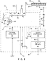
- A capacitance activated switch device, generally designated 40, is best illustrated in
FIG. 2 . Such capacitance activatedswitch device 40 comprises a capacitance means, generally designated 41, having agenerator 42 capable of generating asine wave 44 of apredetermined frequency 46. The capacitance means 41 is grounded at a first ground means 48 and is adapted to at least receive an operatingvoltage 97 associated with an input voltage VINPUT. Afirst resistor 50 of a first predetermined resistive value is internally coupled to thegenerator 42 at afirst end 72 and is externally coupled to at least oneelectrical antenna output 49 at asecond end 73. In operation, suchfirst resistor 50 will enable a first voltage V1 at afirst end 72 and a second voltage V2 at asecond end 73. In a steady state condition, with no electrical load being applied to the at least oneelectrical antenna output 49, such first voltage V1 is equal to the second voltage V2. The capacitance means 41 is adapted for providing at least one firstdigital signal 74, preferably being a plurality of firstdigital signals 74, and at least oneanalog output signal 76 tomicrocontroller 78 capable of executing a predetermined software algorithm. The capacitance means 41 is further adapted for receiving at least one seconddigital signal 75, preferably being a plurality of seconddigital signals 75, from themicrocontroller 78. Preferably, such capacitance means 41 is an electric field imaging device model MC 33794 manufactured by MOTOROLA and/or its spin-off, Freescale Semiconductor, Inc. - The at least one
electrical antenna conductor 52 is electrically coupled to the at least oneelectrical antenna output 49 at one end and to a conductive electrode means 54 at a distal end. The conductive electrode means 54 is rigidly attached to a mountingmember 56. At least one electrical isolator means 58 may be provided in application wheresuch member 56 does not inherently contain dielectric capabilities. - As schematically illustrated in
FIG. 2 , ameans 60 representing an object or human body part is coupled to the third ground means 62, generally being thefloor portion 18. In operation, upon supply of the input voltage VINPUT, thegenerator 42 will generate thesine wave 44 which will be transmitted to the conductive electrode means 54 by the at least oneelectrical antenna conductor 52 enabling generation of anelectrical field 64 having a predetermined depth and at least partially surrounding the conductive electrode means 54. Any grounded object orhuman body part 60 grounded to the third grounding means 62 and entering theelectrical field 64 will produce acapacitive load 66.Such capacitive load 66 will result in second voltage V2 being smaller than the first voltage V1. Continuing movement of theobject 60 toward the conductive electrode means 54 will incrementally increase suchcapacitive load 66 and therefore incrementally decrease the second voltage V2. The maximum capacitance value will be achieved upon contact ofsuch object 60 with the conductive electrode means 54. - The change in the second voltage V2 will be detected by the
microcontroller 78 via at least oneanalog input 76 and the change exceeding a predetermined voltage threshold in the software algorithm will trigger anoutput signal 80 generating at least onecontrol signal 92 to the door controller which is not shown but is well known in the art. Preferably, anoutput driver 90 is disposed intermediate theoutput signal 80 and the at least onecontrol signal 92 to receivesuch output signal 80 and generate the at least onecontrol signal 92 being a voltage signal and further being equal to the input voltage VINPUT. - The software algorithm is capable of differentiating between a gradual movement of the
means 60 within theelectrical field 64 as such gradual movement will result in a gradual change of the second voltage V2 over a first predetermined period of time and an impact between themeans 60 and the conductive electrode means 54 which will result in change of the second voltage V2 over a second predetermined period of time being substantially smaller than such first predetermined period of time. - The capacitance activated
switch device 40 may be adapted with asecond resistor 86 having a second predetermined resistive value which is electrically coupled to the capacitance means 41 via anelectrical path 87 for adjusting thepredetermined frequency 46 and, more importantly, for adjusting a predetermined depth of theelectrical field 64. - The capacitance activated
switch device 40 may further include afirst capacitor 82 having a first predetermined capacitance value generally defining a lower capacitance limit andsecond capacitor 84 having a second predetermined capacitance value generally defining an upper capacitance limit. It will be appreciated that suchfirst capacitor 82 will generate afirst voltage reference 83 defining a predetermined upper limit of the expected voltage from theelectrical field 64 and suchsecond capacitor 84 will generate asecond voltage reference 85 defining a predetermined lower limit of the expected voltage from theelectrical field 64. In a first aspect, such first and second voltage references 83 and 85 respectively may be used by themicrocontroller 78 to measure actual capacitance value of thecapacitive load 66. In a second aspect, thefirst voltage reference 83 may be used by themicrocontroller 78 to identify a broken electrical connection coupled to the capacitance means 41. In a third aspect, themicrocontroller 78 can compensate for environmental temperature or input voltage VINPUT variations by continuously measuring the first and second voltage references 83 and 85 respectively, by continuously comparing actual measurements against their predetermined default values and storing the last calculated difference. In operation, such last calculated difference will be used by themicrocontroller 78 to proportionally adjust the measured second voltage V2 via the software algorithm. - In applications wherein the input voltage VINPUT differs from an operating
voltage 97, which is 12 VDC for MOTOROLA/Freescale Semiconductor, Inc device model MC 33794, the capacitance activatedswitch device 40 may additionally include ameans 96, such as a well knownvoltage regulator 96, for converting input voltage VINPUT into the operatingvoltage 97. - It will be appreciated that means 96 may be also an internal power source such as battery for supplying
such operating voltage 97. - Preferably, the capacitance means 41, the
microcontroller 78, theoutput driver 90, the first andsecond capacitors second resistor 86, and themeans 96 are mounted to a printedcircuit board 98 by one of through hole and surface mount methods. In an alternative embodiment, such components may be disposed within the door controller (not shown). - The reader's attention is now directedto
FIG. 1 illustrating a portion of a transit vehicle, generally designated 10, having afloor member 12 and awall member 14. Adoor 30 is disposed within awall aperture 16 and is driven by adoor drive 34 in one of closing and opening directions to at least partially cover and uncoversuch aperture 16. Thedoor 30 is supported by a door support means 32 which may be integral to door drive 34. Afloor portion 18 disposed adjacent thedoor 30 may be constructed as a planar inclined surface or constructed as a stairwell which is not shown but is well known in the art. Typically, atraction member 19 manufactured from elastomeric or polymer material is applied to a surface ofsuch floor member 12 andfloor portion 18. Thetraction member 19 may be a well known sensitive treadle mat. - Alternatively,
such floor portion 18 may incorporate a movable accessibility device (not shown), such as taught byU.S. Patent 5,775,232 , which extends outwardly from thewall member 14 to accommodate ingress and egress of passengers with disabilities or needing further assistance. The teaching ofU.S. Patent 5,775,232 is hereby incorporated by reference thereto. - A
screen member 20 may be provided within thetransit vehicle 10 for separating aseating area 22 from the standing area defined by thedoor 30 andfloor portion 18. Asecond door 36 supported by a door support means 38 may be disposed within thewall aperture 16 adjacent thefirst door 30. In such arrangement, thefirst door 30 and thesecond door 36 move in opposite directions for covering and uncovering thewall aperture 16. - The structure and operation of the capacitance activated
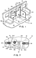
switch device 40 of the first embodiment is illustrated in a combination with an activating member such as touch bar, generally designated 100, which is rigidly attached to atleast door 30 adjacent its leadingedge 31. As best illustrated inFIG. 3 ,such touch bar 100 comprises atubular member 102 having awall 104 and being disposed between anupper housing 110 and alower housing 120 which are rigidly attached to the surface of thedoor 30. - The
upper housing 110 is adapted with afirst cavity 112 for attachment to an end of thetubular member 102, afirst aperture 114 and asecond aperture 116 which is aligned with anaperture 33 disposed within thedoor 30. Thefirst cavity 112 may be provided with anannular grove 117 for housing aresilient member 118 surrounding thetubular member 102. Thefirst aperture 114 is fitted with anend plug 122. - The
lower housing 120 is constructed generally similar to the upper housing except that it does not contain anaperture 116 and is further provided with thecover member 124. - Typically, the upper and
lower housings door 30. It will be appreciated that a metallic electrically conductive substitution may be readily made with an employment of at least oneelectrical isolator 126 disposed intermediate such housings and thedoor 30. - In the preferred embodiment, capacitance activated
switch device 40 is secured within thefirst aperture 114, preferably by theend plug 122. The at least oneelectrical antenna conductor 52 is electrically and rigidly attached to either interior or exterior surfaces of thewall 104 by any well known methods including but not limited to such methods as soldering, brazing or mechanical fastening. - In applications wherein such
tubular member 102 is manufactured from a nonconductive material the at least oneelectrical antenna conductor 52 may include arigid antenna portion 52a longitudinally disposed within thetubular member 102. - The supply voltage VINPUT and the at least one
control signal 92 are provided via awire bundle 130 routed through thesecond aperture 116 and thedoor aperture 33 to the door controller (not shown). - In operation, presence of the supply voltage VINPUT will generate an
electrical field 64 at least partially surrounding thetubular member 102. The passenger approaching thetubular member 102 with any body part, such as hand, arm, shoulder, or torso will create acapacitive load 66 upon entering such at least partially surroundingelectric field 64 causing the value of the second voltage V2 to change. Such change in the second voltage V2 will be detected by the capacitance means 41 and themicrocontroller 78 and followed by generation of theoutput signal 80 and subsequently followed by generation of at least onecontrol signal 92 which will be interpreted by the door controller (not shown) as a request to open or reopen thedoor 30 enabling thedoor drive 34 to move thedoor 30 in an opening direction. The at least onecontrol signal 92 may be further used to energize visual indicators (not shown) disposed above thedoor 30 or enable other annunciation or control functions. - It will be appreciated that since a capacitor is defined as a pair of electrical conductors separated by a space, any coating or non conductive material encasing such
tubular member 102 will not disrupt operation of the capacitance activatedswitch device 40. - It also has been discovered during testing that a passenger wearing a winter glove or a heavy winter coat will generate a capacitance load upon entering the
electric field 64, thus ; enabling opening of thedoor 30. - In an alternative embodiment, the capacitance activated
switch device 40 may be mounted remotely, as best illustrated by reference 99 inFIG. 1 . It will be appreciated that in such installation, the capacitance activatedswitch device 40 will be disposed within ahousing 91 and thewire bundle 130 will be routed through the vehicle structure, thedoor 30 and theupper housing 110 andsuch wire bundle 130 will further contain the at least oneelectrical conductor 52. Preferably, such at least oneelectrical antenna conductor 52 will be shielded and having ashield conductor 164 coupled to ashield output 51 of the capacitance activatedswitch device 40. - The structure of the capacitance activated
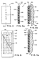
switch device 40 of another embodiment is illustrated in a combination with a touch switch type, generally designated 150, which may be rigidly attached to thedoor 30 at inner and outer surface thereof,wind screen 20 or in other predetermined locations disposed within thetransit vehicle 10. - As best illustrated in
FIGS. 4 and 5a-5c ,such touch switch 150 has a predetermined configuration and comprises a frontconductive member 152 and an opposed rearconductive member 154 separated with aninsulator member 156. The at least oneelectrical antenna conductor 52 is electrically coupled to the frontconductive member 152 and theshield conductor 164 is electrically coupled to the rearconductive member 154. An outerprotective member 158 manufactured from a non-conductive material, preferably a polymer or an elastomer, may be employed to protect thetouch switch 150 from environmental factors, such as moisture, dust and dirt.Indicia 160 may be disposed within the outerprotective member 158 or disposed on the frontconductive member 152 for providing a predetermined instruction to passengers. As has been aforementioned, at least oneelectrical isolator 126 may be disposed intermediate the rearconductive member 154 and the mounting structure, such asdoor 30 orwind screen 20, in applications wherein such asdoor 30 orwind screen 20 are manufactured from any conductive materials. - The
touch switch 150 may be attached with the use of an adhesive 166 applied to the back surface of the rearconductive member 154 or theelectrical isolator 126 or with the use of well known mechanical fasteners. - Preferably, for manufacturing cost efficiency, the
touch switch 150 is manufactured from a well known dual side printed circuit board material, wherein the frontconductive member 152 and the rearconductive member 154 are copper foil of a predetermined weight and theinsulator member 156 is an epoxy-glass FR-4 (G-10) board of a predetermined thickness. - In an alternative embodiment, the
touch switch 150 is adapted with ahousing member 168 disposed intermediate the rearconductive member 154 and the mounting structure, such as thedoor 30, as best illustrated inFIG. 5b or disposed planar with thetouch switch 150 as best illustrated inFIG. 5c .Such housing 168 is for locally containing the capacitance activatedswitch device 40. - Those skilled in the art will readily understand that the embodiment of
FIG. 5b will be most suitable fortouch switches 150 having a round, rectangular or square shape while the embodiment ofFIG. 5c will be most suitable fortouch switches 150 being used to repalce a well known tape switch which is generally characterized by its length being significantly larger than its width. - It will be further understood that such touch switches 150 may be employed for driving the
door 30 in a closing direction when the door controller (not shown) receives a remote door closing enabling signal. - It will be appreciated that the capacitance activated
switch device 40 may be further used in combination with thedoor 30 having only ahandle 170 rigidly attached to the surface thereof as best illustrated inFIG. 6 . In such embodiment, thehandle 170 will produce anelectric field 64 through the at least oneelectrical antenna conductor 52 connected thereto. - It will be further appreciated that such at least one
electrical antenna conductor 52 connected directly to thedoor 30 manufactured from a conductive metallic material, including but not limited to aluminum and steel, will generate anelectrical field 64 over the conductive surface of thedoor 30 thus enabling to use thedoor 30 as a touch switch and opensuch door 30 at any conductive portion thereof. - It will be understood that a typical
window glass portion 174 ofsuch door 30 will be isolated from such conductive surface and will not produce theelectric field 64. However, thewindow glass portion 174 containing at least one and preferably an array of embeddedelectrodes 176 coupled to the at least oneelectrical antenna conductor 52, as illustrated inFIG. 6 , will produce suchelectric field 64. It will be appreciated that utility of such embodiment would be especially pertinent in applications utilizing what is well known as an "all glass"door 30. The at least oneelectrical antenna conductor 52 may be routed within thewire bundle 130. - The structure and operation of the capacitance activated
switch device 40 for employment in obstruction detection is best illustrated inFIGS. 7 and8 . The leadingedge 31 of thedoor 30 is typically adapted with a softresilient edge 200 being an extruded elastomer such as rubber. Theedge 200 is fitted with at least onelongitudinal aperture 202 adjacent the outer surface of theedge 200 to enable compression thereof upon contact with theopposed edge 200 attached to thedoor 36 whensuch doors aperture 202 is closed at each end to provide a sealed chamber. - Placement of the at least one
electrical conductor 52 within such at least oneaperture 202 will create theelectrical field 64 at least partially surrounding theedge 200. As thedoor 30 is being driven in a closed direction 204, a presence of thepassenger 60 in its path, as best illustrated inFIG. 7 , will generate acapacitive load 66 at apredetermined distance 210 from theedge 200 thus enabling themicrocontroller 78 to generate the at least onecontrol signal 92 which will be used by the door controller (not shown) to either discontinue movement of thedoor 30 in a closing direction 204 or reverse the direction of the movement to reopen thedoor 30. Thus, the advantage of the present invention is that such obstruction will be at least partially detected prior to a physical contact of thepassenger 60 with thedoor 30. It will be appreciated that anobject 61, such as briefcase inFIG. 7 , coupled to apassenger 60 and capable of generatingsuch capacitive load 66 will enable themicrocontroller 78 to generate the at least onecontrol signal 92. - In another embodiment of the present invention, the at least one
electrode 178 may be embedded within at least a portion of thetraction member 19, with such portion disposed adjacent to thedoor 30. In such embodiment, a passenger standing on such will trigger the at least onecontrol signal 92 preventing closing of thedoor 30.
Claims (17)
- A capacitance activated switch device for providing at least one control signal upon supply of an input voltage and an engagement of a capacitive load with an electrical field, said capacitance activated switch device comprising:(a) a capacitance means (41) associated with said electrical field, said capacitance means (41) including:(i) a generator (42) capable of generating a sine wave (44) of a predetermined frequency (46);(ii) at least one antenna output (49) for enabling transmission of said sine wave (44);(iii) a first resistor (50) having a predetermined resistive value and having a first lead (72) coupled to said generator (42) and a second lead (73) coupled to said at least one antenna output (49), said first resistor (50) enabling generation of a first voltage at said first lead (72) and a second voltage at said second lead (73) ;(iv) a first communication means for providing an analog signal associated with said second voltage; and(v) a second communication means for providing a predetermined plurality of first digital signals (74) and receiving a predetermined plurality of second digital signal (75);(b) a first ground coupled to said capacitance means;(c) an operating voltage associated with said input voltage and applied to said capacitance means for enabling said generator to generate said sign wave;(d) a microcontroller (78) coupled to said capacitance means (41) and having at least a third communication means being in electrical communication with said first communication means of said capacitance means (41) for receiving said analog signal and a forth communication means being in electrical communication with said second communication means of said capacitance means (41) for receiving said predetermined plurality of said first digital signals (74) and providing said predetermined plurality of said second digital signals (75), said microcontroller (78) providing an output signal upon receipt of said second voltage signal; and(e) an output driver means coupled to said microcontroller (78) for receiving said output signal and for providing said at least one control signal,wherein said microcontroller (78) is programmed for executing a predetermined software algorithm capable of differentiating between a gradual movement of said capacitive load within said electrical field resulting in a gradual change of said second voltage over a first predetermined period of time and an accelerated movement of said capacitive load through said electrical field resulting in a change of said second voltage over a second predetermined period of time, said second predetermined period of time being substantially smaller than said first predetermined period of time.
- A capacitance activated switch device according to claim 1, wherein said capacitance activated switch device includes a second resistor having a second predetermined resistive value and being electrically coupled to said capacitance means for adjusting said predetermined frequency and for defining a predetermined depth of said electrical field.
- A capacitance activated switch device according to claim 1, wherein said capacitance activated switch device includes a means coupled to said input voltage for converting thereof into said operating voltage, wherein said input voltage is one of a smaller and a greater magnitude than said operating voltage.
- A capacitance activated switch device according to claim 1, wherein said capacitance activated switch device includes a first capacitor having a predetermined capacitance value for generally defining a lower capacitance limit of said capacitance means, said first capacitor enabling generation of a first voltage reference defining a predetermined upper voltage limit associated with said capacitive load engaging said electrical field.
- A capacitance activated switch device according to claim 1, wherein said capacitance activated switch device includes a second capacitor having a predetermined capacitance value for generally defining an upper capacitance limit of said capacitance means, said second capacitor enabling generation of a second voltage reference defining a predetermined lower voltage limit associated with said capacitive load engaging said electrical field.
- A capacitance activated switch device according to claim 1, wherein said capacitance means includes at least one shield output.
- A capacitance activated switch device according to claim 1, wherein said capacitance activated switch device includes a printed circuit board.
- A capacitance activated switch device according to claim 1, wherein said at least one control signal is a voltage signal.
- A capacitance activated switch device according to claim 8, wherein said voltage signal is equal in magnitude to said input voltage.
- A capacitance activated switch device according to claim 1, wherein said capacitance activated switch device includes a power source disposed therein for providing said operating voltage.
- A capacitance activated switch device according to claim 10, wherein said internal power source is an electrical battery.
- A capacitance activated switch device according to claim 1, wherein said capacitance activated switch device includes a housing.
- A capacitance activated switch device according to claim 1, wherein said predetermined software algorithm enables said microcontroller to provide said output signal when said second voltage is greater than a predetermined voltage threshold.
- A capacitance activated switch device according to claim 1, wherein said capacitance activated switch device includes at least one electrical antenna conductor connected to said at least one antenna output for transmitting said sine wave.
- A capacitance activated switch device according to claim 14, wherein said capacitance activated switch device includes an activating member coupled to said at least one electrical antenna conductor and attached to a mounting structure.
- A capacitance activated switch device according to claim 15, wherein said activating member is manufactured from one of an electrically conductive, an electrically nonconductive material and a combination thereof.
- A capacitance activated switch device according to claim 16, wherein said capacitance activated switch device includes an electrically nonconductive member disposed intermediate said activating member and said mounting structure, wherein said activating member and said mounting structure are electrically conductive.
Priority Applications (1)
| Application Number | Priority Date | Filing Date | Title |
|---|---|---|---|
| EP08160387A EP1983648A1 (en) | 2004-04-16 | 2005-04-13 | Capacitance activated switch device |
Applications Claiming Priority (3)
| Application Number | Priority Date | Filing Date | Title |
|---|---|---|---|
| US56316704P | 2004-04-16 | 2004-04-16 | |
| US11/084,789 US7208694B2 (en) | 2004-04-16 | 2005-03-18 | Capacitance activated switch device |
| PCT/US2005/012367 WO2005107071A2 (en) | 2004-04-16 | 2005-04-13 | Capacitance activated switch device |
Related Child Applications (2)
| Application Number | Title | Priority Date | Filing Date |
|---|---|---|---|
| EP08160387A Division EP1983648A1 (en) | 2004-04-16 | 2005-04-13 | Capacitance activated switch device |
| EP08160387.0 Division-Into | 2008-07-15 |
Publications (2)
| Publication Number | Publication Date |
|---|---|
| EP1745547A2 EP1745547A2 (en) | 2007-01-24 |
| EP1745547B1 true EP1745547B1 (en) | 2010-03-24 |
Family
ID=34966402
Family Applications (2)
| Application Number | Title | Priority Date | Filing Date |
|---|---|---|---|
| EP08160387A Withdrawn EP1983648A1 (en) | 2004-04-16 | 2005-04-13 | Capacitance activated switch device |
| EP05735312A Expired - Lifetime EP1745547B1 (en) | 2004-04-16 | 2005-04-13 | Capacitance activated switch device |
Family Applications Before (1)
| Application Number | Title | Priority Date | Filing Date |
|---|---|---|---|
| EP08160387A Withdrawn EP1983648A1 (en) | 2004-04-16 | 2005-04-13 | Capacitance activated switch device |
Country Status (9)
| Country | Link |
|---|---|
| US (1) | US7208694B2 (en) |
| EP (2) | EP1983648A1 (en) |
| JP (1) | JP4825196B2 (en) |
| AT (1) | ATE462227T1 (en) |
| AU (1) | AU2005239317B2 (en) |
| CA (1) | CA2563412C (en) |
| DE (1) | DE602005020129D1 (en) |
| ES (1) | ES2343192T3 (en) |
| WO (1) | WO2005107071A2 (en) |
Families Citing this family (13)
| Publication number | Priority date | Publication date | Assignee | Title |
|---|---|---|---|---|
| KR101185145B1 (en) * | 2006-02-13 | 2012-09-24 | 삼성전자주식회사 | Apparatus and method for setting adaptively reference sensing boundary of touch sensor |
| EP2013955A4 (en) * | 2006-04-21 | 2010-10-13 | Wabtec Holding Corp | Two-wire adapter |
| US7436136B2 (en) * | 2006-09-26 | 2008-10-14 | Arvinmeritor Light Vehicle Systems - France | Camera based anti-pinch system |
| US20080150712A1 (en) * | 2006-12-21 | 2008-06-26 | Ford Global Technologies, Llc | Tire pressure monitoring (tpm) and remote keyless entry (rke) system |
| GB0712688D0 (en) * | 2007-06-29 | 2007-08-08 | Memco Ltd | Detector |
| US8358226B2 (en) * | 2007-10-28 | 2013-01-22 | Synaptics Incorporated | Determining actuation of multi-sensor-electrode capacitive buttons |
| FI121979B (en) * | 2008-03-26 | 2011-06-30 | Elsi Technologies Oy | Adapter component for measuring system |
| DE102008053113A1 (en) * | 2008-10-25 | 2010-05-06 | Brose Fahrzeugteile Gmbh & Co. Kg, Hallstadt | Drive arrangement for the motorized adjustment of an adjusting element in a motor vehicle |
| WO2011053591A1 (en) * | 2009-10-26 | 2011-05-05 | Crane Merchandising Systems, Inc. | All-in-one door switch interface to multiple controllers within a vending machine |
| EP2921629B1 (en) * | 2013-10-15 | 2018-12-05 | Iveco France S.A.S. | Method for controlling the opening of the doors of a mass transit passenger vehicle |
| US10353523B2 (en) | 2016-05-10 | 2019-07-16 | Westinghouse Air Brake Technologies Corporation | Passenger communication lighting |
| CN209112194U (en) * | 2018-08-29 | 2019-07-16 | 中车青岛四方机车车辆股份有限公司 | Activating device for rail vehicle and carriage and rail vehicle having the same |
| EP3736985A1 (en) | 2019-05-10 | 2020-11-11 | Captron Electronic GmbH | Illuminated switch |
Family Cites Families (23)
| Publication number | Priority date | Publication date | Assignee | Title |
|---|---|---|---|---|
| US4022996A (en) * | 1975-09-11 | 1977-05-10 | Midland-Ross Corporation | Switch mechanism for bus doors with manually operated touch bar |
| US4371762A (en) * | 1979-07-26 | 1983-02-01 | Vapor Corporation | Contactless pressure sensitive switch |
| US4431882A (en) * | 1982-08-12 | 1984-02-14 | W. H. Brady Co. | Transparent capacitance membrane switch |
| JPS6125087A (en) * | 1984-07-16 | 1986-02-03 | Honda Motor Co Ltd | Object detector |
| US4562315A (en) * | 1984-09-20 | 1985-12-31 | W. H. Brady Co. | Capacitance membrane switch |
| JPS6172934U (en) * | 1984-10-17 | 1986-05-17 | ||
| US5118910A (en) * | 1990-03-12 | 1992-06-02 | Tapeswitch Corporation Of America | Illuminated, pressure-actuated switch |
| US5134259A (en) * | 1990-04-25 | 1992-07-28 | Page Jr Lawrence C | Palm button switch apparatus |
| DE4113487C1 (en) * | 1991-04-25 | 1992-11-05 | Fleischgrosshandel Hans-Werner & Bernd Meixner Gmbh, 6301 Wettenberg, De | |
| US6064165A (en) * | 1992-04-22 | 2000-05-16 | Nartron Corporation | Power window or panel controller |
| AU5671396A (en) | 1995-05-08 | 1996-11-29 | Massachusetts Institute Of Technology | System for non-contact sensing and signalling using human bo dy as signal transmission medium |
| IL115876A (en) * | 1995-11-05 | 1998-02-08 | Sensotech Ltd | Automatic door operating system with sensor for steps |
| US5775232A (en) | 1997-02-14 | 1998-07-07 | Vapor Corporation | Bridge plate for a mass transit vehicle |
| US5942815A (en) * | 1997-10-03 | 1999-08-24 | Sheldahl, Inc. | Programmable capacitive horn switch |
| JP2002525702A (en) | 1998-09-14 | 2002-08-13 | コーニンクレッカ フィリップス エレクトロニクス エヌ ヴィ | Electronic communication system |
| DE59910461D1 (en) | 1999-10-05 | 2004-10-14 | Alcan Tech & Man Ag | assemblies connection |
| US6724324B1 (en) * | 2000-08-21 | 2004-04-20 | Delphi Technologies, Inc. | Capacitive proximity sensor |
| EP1235190B8 (en) | 2001-02-21 | 2005-06-22 | Kiekert Aktiengesellschaft | Keyless actuating and/or locking device |
| DE10163778B4 (en) * | 2001-06-27 | 2008-01-24 | Witte-Velbert Gmbh & Co. Kg | Handle with integrated antenna and sensor electrode |
| US6661410B2 (en) * | 2001-09-07 | 2003-12-09 | Microsoft Corporation | Capacitive sensing and data input device power management |
| US20030085679A1 (en) * | 2001-10-28 | 2003-05-08 | Bledin Anthony G. | Segmented capacitive closure obstruction sensor |
| JP4003453B2 (en) * | 2001-12-26 | 2007-11-07 | アイシン精機株式会社 | Human body detection device |
| ATA14112002A (en) * | 2002-09-19 | 2004-01-15 | Knorr Bremse Gmbh | SWING SLIDING |
-
2005
- 2005-03-18 US US11/084,789 patent/US7208694B2/en not_active Expired - Lifetime
- 2005-04-13 CA CA2563412A patent/CA2563412C/en not_active Expired - Lifetime
- 2005-04-13 EP EP08160387A patent/EP1983648A1/en not_active Withdrawn
- 2005-04-13 WO PCT/US2005/012367 patent/WO2005107071A2/en not_active Ceased
- 2005-04-13 DE DE602005020129T patent/DE602005020129D1/en not_active Expired - Lifetime
- 2005-04-13 AT AT05735312T patent/ATE462227T1/en not_active IP Right Cessation
- 2005-04-13 JP JP2007508470A patent/JP4825196B2/en not_active Expired - Lifetime
- 2005-04-13 ES ES05735312T patent/ES2343192T3/en not_active Expired - Lifetime
- 2005-04-13 AU AU2005239317A patent/AU2005239317B2/en not_active Ceased
- 2005-04-13 EP EP05735312A patent/EP1745547B1/en not_active Expired - Lifetime
Also Published As
| Publication number | Publication date |
|---|---|
| US20050231147A1 (en) | 2005-10-20 |
| JP4825196B2 (en) | 2011-11-30 |
| EP1745547A2 (en) | 2007-01-24 |
| JP2007533268A (en) | 2007-11-15 |
| ATE462227T1 (en) | 2010-04-15 |
| WO2005107071A2 (en) | 2005-11-10 |
| ES2343192T3 (en) | 2010-07-26 |
| WO2005107071A3 (en) | 2006-02-23 |
| AU2005239317A1 (en) | 2005-11-10 |
| DE602005020129D1 (en) | 2010-05-06 |
| US7208694B2 (en) | 2007-04-24 |
| AU2005239317B2 (en) | 2009-03-12 |
| EP1983648A1 (en) | 2008-10-22 |
| CA2563412C (en) | 2014-07-08 |
| CA2563412A1 (en) | 2005-11-10 |
Similar Documents
| Publication | Publication Date | Title |
|---|---|---|
| EP1745547B1 (en) | Capacitance activated switch device | |
| US6499359B1 (en) | Compressible capacitance sensor for determining the presence of an object | |
| US6946853B2 (en) | Non-contact proximity sensor | |
| US8228077B2 (en) | Anti-pinch sensor | |
| US7046129B2 (en) | Device for detecting an obstacle in the opening range of a movable closure element | |
| EP1154110B1 (en) | Trapping protector | |
| US7132642B2 (en) | Anti-entrapment systems for preventing objects from being entrapped by translating devices | |
| US6968746B2 (en) | Anti-entrapment system | |
| US8305092B2 (en) | Capacitive sensing system and method | |
| US20090212849A1 (en) | Capacitive moisture independent crush protection | |
| CA2464747A1 (en) | Multizone capacitive anti-pinch system | |
| WO2014140888A2 (en) | Combination capacitive and resistive obstacle sensor | |
| JP2007533268A5 (en) | ||
| CN101636908A (en) | Arrangement for the detection of body parts by absorbing an electric near field | |
| CN105121261A (en) | Capacitive trim sensor and system | |
| WO2004069590A3 (en) | Capacitive detection system, particularly for a motor vehicle interior | |
| EP1361096A3 (en) | Device for detecting an obstacle in the opening area of a movable closure element of a vehicle | |
| EP3310984B1 (en) | Capacitive jam protection | |
| EP4286637A1 (en) | Non-contact-type pinch prevention device | |
| KR20210032203A (en) | Combined type sensor with contact sensing and contactless sensing | |
| DE102023128663A1 (en) | VEHICLE ARRANGEMENT WITH A CAPACITIVE SENSOR | |
| KR20220109176A (en) | Anti Pinch System Using Non-Contact Body Perceiveiving Sensor |
Legal Events
| Date | Code | Title | Description |
|---|---|---|---|
| PUAI | Public reference made under article 153(3) epc to a published international application that has entered the european phase |
Free format text: ORIGINAL CODE: 0009012 |
|
| 17P | Request for examination filed |
Effective date: 20061113 |
|
| AK | Designated contracting states |
Kind code of ref document: A2 Designated state(s): AT BE BG CH CY CZ DE DK EE ES FI FR GB GR HU IE IS IT LI LT LU MC NL PL PT RO SE SI SK TR |
|
| DAX | Request for extension of the european patent (deleted) | ||
| 17Q | First examination report despatched |
Effective date: 20080304 |
|
| GRAP | Despatch of communication of intention to grant a patent |
Free format text: ORIGINAL CODE: EPIDOSNIGR1 |
|
| GRAS | Grant fee paid |
Free format text: ORIGINAL CODE: EPIDOSNIGR3 |
|
| GRAA | (expected) grant |
Free format text: ORIGINAL CODE: 0009210 |
|
| AK | Designated contracting states |
Kind code of ref document: B1 Designated state(s): AT BE BG CH CY CZ DE DK EE ES FI FR GB GR HU IE IS IT LI LT LU MC NL PL PT RO SE SI SK TR |
|
| REG | Reference to a national code |
Ref country code: GB Ref legal event code: FG4D |
|
| REG | Reference to a national code |
Ref country code: CH Ref legal event code: EP |
|
| REG | Reference to a national code |
Ref country code: IE Ref legal event code: FG4D |
|
| REF | Corresponds to: |
Ref document number: 602005020129 Country of ref document: DE Date of ref document: 20100506 Kind code of ref document: P |
|
| REG | Reference to a national code |
Ref country code: NL Ref legal event code: VDEP Effective date: 20100324 |
|
| REG | Reference to a national code |
Ref country code: ES Ref legal event code: FG2A Ref document number: 2343192 Country of ref document: ES Kind code of ref document: T3 |
|
| PG25 | Lapsed in a contracting state [announced via postgrant information from national office to epo] |
Ref country code: LT Free format text: LAPSE BECAUSE OF FAILURE TO SUBMIT A TRANSLATION OF THE DESCRIPTION OR TO PAY THE FEE WITHIN THE PRESCRIBED TIME-LIMIT Effective date: 20100324 |
|
| LTIE | Lt: invalidation of european patent or patent extension |
Effective date: 20100324 |
|
| PG25 | Lapsed in a contracting state [announced via postgrant information from national office to epo] |
Ref country code: AT Free format text: LAPSE BECAUSE OF FAILURE TO SUBMIT A TRANSLATION OF THE DESCRIPTION OR TO PAY THE FEE WITHIN THE PRESCRIBED TIME-LIMIT Effective date: 20100324 Ref country code: FI Free format text: LAPSE BECAUSE OF FAILURE TO SUBMIT A TRANSLATION OF THE DESCRIPTION OR TO PAY THE FEE WITHIN THE PRESCRIBED TIME-LIMIT Effective date: 20100324 Ref country code: SI Free format text: LAPSE BECAUSE OF FAILURE TO SUBMIT A TRANSLATION OF THE DESCRIPTION OR TO PAY THE FEE WITHIN THE PRESCRIBED TIME-LIMIT Effective date: 20100324 Ref country code: PL Free format text: LAPSE BECAUSE OF FAILURE TO SUBMIT A TRANSLATION OF THE DESCRIPTION OR TO PAY THE FEE WITHIN THE PRESCRIBED TIME-LIMIT Effective date: 20100324 |
|
| PG25 | Lapsed in a contracting state [announced via postgrant information from national office to epo] |
Ref country code: BE Free format text: LAPSE BECAUSE OF FAILURE TO SUBMIT A TRANSLATION OF THE DESCRIPTION OR TO PAY THE FEE WITHIN THE PRESCRIBED TIME-LIMIT Effective date: 20100324 Ref country code: NL Free format text: LAPSE BECAUSE OF FAILURE TO SUBMIT A TRANSLATION OF THE DESCRIPTION OR TO PAY THE FEE WITHIN THE PRESCRIBED TIME-LIMIT Effective date: 20100324 Ref country code: SE Free format text: LAPSE BECAUSE OF FAILURE TO SUBMIT A TRANSLATION OF THE DESCRIPTION OR TO PAY THE FEE WITHIN THE PRESCRIBED TIME-LIMIT Effective date: 20100324 Ref country code: RO Free format text: LAPSE BECAUSE OF FAILURE TO SUBMIT A TRANSLATION OF THE DESCRIPTION OR TO PAY THE FEE WITHIN THE PRESCRIBED TIME-LIMIT Effective date: 20100324 Ref country code: GR Free format text: LAPSE BECAUSE OF FAILURE TO SUBMIT A TRANSLATION OF THE DESCRIPTION OR TO PAY THE FEE WITHIN THE PRESCRIBED TIME-LIMIT Effective date: 20100625 Ref country code: EE Free format text: LAPSE BECAUSE OF FAILURE TO SUBMIT A TRANSLATION OF THE DESCRIPTION OR TO PAY THE FEE WITHIN THE PRESCRIBED TIME-LIMIT Effective date: 20100324 |
|
| PG25 | Lapsed in a contracting state [announced via postgrant information from national office to epo] |
Ref country code: SK Free format text: LAPSE BECAUSE OF FAILURE TO SUBMIT A TRANSLATION OF THE DESCRIPTION OR TO PAY THE FEE WITHIN THE PRESCRIBED TIME-LIMIT Effective date: 20100324 Ref country code: CZ Free format text: LAPSE BECAUSE OF FAILURE TO SUBMIT A TRANSLATION OF THE DESCRIPTION OR TO PAY THE FEE WITHIN THE PRESCRIBED TIME-LIMIT Effective date: 20100324 Ref country code: BG Free format text: LAPSE BECAUSE OF FAILURE TO SUBMIT A TRANSLATION OF THE DESCRIPTION OR TO PAY THE FEE WITHIN THE PRESCRIBED TIME-LIMIT Effective date: 20100624 Ref country code: IS Free format text: LAPSE BECAUSE OF FAILURE TO SUBMIT A TRANSLATION OF THE DESCRIPTION OR TO PAY THE FEE WITHIN THE PRESCRIBED TIME-LIMIT Effective date: 20100724 Ref country code: MC Free format text: LAPSE BECAUSE OF NON-PAYMENT OF DUE FEES Effective date: 20100430 |
|
| REG | Reference to a national code |
Ref country code: CH Ref legal event code: PL |
|
| PLBE | No opposition filed within time limit |
Free format text: ORIGINAL CODE: 0009261 |
|
| STAA | Information on the status of an ep patent application or granted ep patent |
Free format text: STATUS: NO OPPOSITION FILED WITHIN TIME LIMIT |
|
| PG25 | Lapsed in a contracting state [announced via postgrant information from national office to epo] |
Ref country code: IE Free format text: LAPSE BECAUSE OF NON-PAYMENT OF DUE FEES Effective date: 20100413 Ref country code: DK Free format text: LAPSE BECAUSE OF FAILURE TO SUBMIT A TRANSLATION OF THE DESCRIPTION OR TO PAY THE FEE WITHIN THE PRESCRIBED TIME-LIMIT Effective date: 20100324 Ref country code: PT Free format text: LAPSE BECAUSE OF FAILURE TO SUBMIT A TRANSLATION OF THE DESCRIPTION OR TO PAY THE FEE WITHIN THE PRESCRIBED TIME-LIMIT Effective date: 20100726 |
|
| PG25 | Lapsed in a contracting state [announced via postgrant information from national office to epo] |
Ref country code: CH Free format text: LAPSE BECAUSE OF NON-PAYMENT OF DUE FEES Effective date: 20100430 Ref country code: LI Free format text: LAPSE BECAUSE OF NON-PAYMENT OF DUE FEES Effective date: 20100430 |
|
| 26N | No opposition filed |
Effective date: 20101228 |
|
| REG | Reference to a national code |
Ref country code: FR Ref legal event code: ST Effective date: 20111125 |
|
| PG25 | Lapsed in a contracting state [announced via postgrant information from national office to epo] |
Ref country code: FR Free format text: LAPSE BECAUSE OF NON-PAYMENT OF DUE FEES Effective date: 20100525 |
|
| PG25 | Lapsed in a contracting state [announced via postgrant information from national office to epo] |
Ref country code: CY Free format text: LAPSE BECAUSE OF FAILURE TO SUBMIT A TRANSLATION OF THE DESCRIPTION OR TO PAY THE FEE WITHIN THE PRESCRIBED TIME-LIMIT Effective date: 20100324 |
|
| PG25 | Lapsed in a contracting state [announced via postgrant information from national office to epo] |
Ref country code: HU Free format text: LAPSE BECAUSE OF FAILURE TO SUBMIT A TRANSLATION OF THE DESCRIPTION OR TO PAY THE FEE WITHIN THE PRESCRIBED TIME-LIMIT Effective date: 20100925 Ref country code: LU Free format text: LAPSE BECAUSE OF NON-PAYMENT OF DUE FEES Effective date: 20100413 |
|
| PG25 | Lapsed in a contracting state [announced via postgrant information from national office to epo] |
Ref country code: TR Free format text: LAPSE BECAUSE OF FAILURE TO SUBMIT A TRANSLATION OF THE DESCRIPTION OR TO PAY THE FEE WITHIN THE PRESCRIBED TIME-LIMIT Effective date: 20100324 |
|
| PGFP | Annual fee paid to national office [announced via postgrant information from national office to epo] |
Ref country code: DE Payment date: 20210427 Year of fee payment: 17 Ref country code: IT Payment date: 20210329 Year of fee payment: 17 |
|
| PGFP | Annual fee paid to national office [announced via postgrant information from national office to epo] |
Ref country code: ES Payment date: 20210510 Year of fee payment: 17 Ref country code: GB Payment date: 20210415 Year of fee payment: 17 |
|
| REG | Reference to a national code |
Ref country code: DE Ref legal event code: R119 Ref document number: 602005020129 Country of ref document: DE |
|
| GBPC | Gb: european patent ceased through non-payment of renewal fee |
Effective date: 20220413 |
|
| PG25 | Lapsed in a contracting state [announced via postgrant information from national office to epo] |
Ref country code: GB Free format text: LAPSE BECAUSE OF NON-PAYMENT OF DUE FEES Effective date: 20220413 Ref country code: DE Free format text: LAPSE BECAUSE OF NON-PAYMENT OF DUE FEES Effective date: 20221103 |
|
| REG | Reference to a national code |
Ref country code: ES Ref legal event code: FD2A Effective date: 20230526 |
|
| PG25 | Lapsed in a contracting state [announced via postgrant information from national office to epo] |
Ref country code: IT Free format text: LAPSE BECAUSE OF NON-PAYMENT OF DUE FEES Effective date: 20220413 |
|
| P01 | Opt-out of the competence of the unified patent court (upc) registered |
Effective date: 20230530 |
|
| PG25 | Lapsed in a contracting state [announced via postgrant information from national office to epo] |
Ref country code: ES Free format text: LAPSE BECAUSE OF NON-PAYMENT OF DUE FEES Effective date: 20220414 |