EP1745407B1 - Reading device for reading out computer-generated lithograms - Google Patents
Reading device for reading out computer-generated lithograms Download PDFInfo
- Publication number
- EP1745407B1 EP1745407B1 EP05737397A EP05737397A EP1745407B1 EP 1745407 B1 EP1745407 B1 EP 1745407B1 EP 05737397 A EP05737397 A EP 05737397A EP 05737397 A EP05737397 A EP 05737397A EP 1745407 B1 EP1745407 B1 EP 1745407B1
- Authority
- EP
- European Patent Office
- Prior art keywords
- image data
- reader according
- evaluation
- reader
- display
- Prior art date
- Legal status (The legal status is an assumption and is not a legal conclusion. Google has not performed a legal analysis and makes no representation as to the accuracy of the status listed.)
- Expired - Fee Related
Links
Images


Classifications
-
- G—PHYSICS
- G06—COMPUTING; CALCULATING OR COUNTING
- G06K—GRAPHICAL DATA READING; PRESENTATION OF DATA; RECORD CARRIERS; HANDLING RECORD CARRIERS
- G06K7/00—Methods or arrangements for sensing record carriers, e.g. for reading patterns
- G06K7/10—Methods or arrangements for sensing record carriers, e.g. for reading patterns by electromagnetic radiation, e.g. optical sensing; by corpuscular radiation
- G06K7/10544—Methods or arrangements for sensing record carriers, e.g. for reading patterns by electromagnetic radiation, e.g. optical sensing; by corpuscular radiation by scanning of the records by radiation in the optical part of the electromagnetic spectrum
- G06K7/10712—Fixed beam scanning
-
- G—PHYSICS
- G06—COMPUTING; CALCULATING OR COUNTING
- G06K—GRAPHICAL DATA READING; PRESENTATION OF DATA; RECORD CARRIERS; HANDLING RECORD CARRIERS
- G06K7/00—Methods or arrangements for sensing record carriers, e.g. for reading patterns
- G06K7/10—Methods or arrangements for sensing record carriers, e.g. for reading patterns by electromagnetic radiation, e.g. optical sensing; by corpuscular radiation
-
- G—PHYSICS
- G06—COMPUTING; CALCULATING OR COUNTING
- G06K—GRAPHICAL DATA READING; PRESENTATION OF DATA; RECORD CARRIERS; HANDLING RECORD CARRIERS
- G06K19/00—Record carriers for use with machines and with at least a part designed to carry digital markings
- G06K19/06—Record carriers for use with machines and with at least a part designed to carry digital markings characterised by the kind of the digital marking, e.g. shape, nature, code
- G06K2019/06215—Aspects not covered by other subgroups
- G06K2019/0629—Holographic, diffractive or retroreflective recording
Definitions
- the present invention relates to a reading device for reading computer-generated lithograms.
- Computer-generated lithograms are two-dimensional point matrices preferred with very small dimensions, which consist of individual points with different optical properties.
- the lithograms are preferably formed as holograms, but can also be directly readable, ie without diffraction of the incident light micro-texts or micro-images are generated with the lithograms.
- a coherent electromagnetic wave in particular light wave by diffraction in transmission or reflection images and / or data
- the different optical properties of the individual points can be reflection properties, for example by surface topography, varying optical path lengths in the material of the storage medium (refractive indices) or color values of the material.
- the optical properties of the individual points are calculated by a computer, so it is so-called computer-generated holograms (CGH) or generally computer-generated lithographs.
- CGH computer-generated holograms
- the individual points of the lithogram are written into the material during the writing, wherein the focus lies in the area of the surface or in the material of the storage medium.
- a Focusing causes a small area of influence on the material of the storage medium in the area of the focus, so that a multiplicity of points of the lithogram can be written in a small area.
- the computer-generated lithogram By scanning an intensity-modulated write beam, a surface with an irregular point distribution, the computer-generated lithogram, thus arises. This can be used to identify, identify and individualize any objects.
- a resolution of about 25,000 dpi is preferred.
- only comparatively small areas are described in computer-generated lithography. These are for example 1 to 5 mm 2 in size, although other sizes are possible.
- the accuracy of the writing pattern in a lithograph for producing digital holograms of, for example, 1000 ⁇ 1000 dots on an area of 1 ⁇ 1 mm 2 must be about ⁇ 0.1 ⁇ m in both orthogonal directions.
- the write speed should be about 1 Mpixel / s, so that one lithograph can be written at a time of about 1 s or less.
- the computer-generated lithograms explained above can carry different information.
- the computer-generated lithogram can carry holographic information which, when read out, that is to say during reproduction, reproduces directly readable information (writing, image, graphics).
- the information read out can be encrypted, in particular digitized.
- the reproduced hologram contains a digital matrix similar to an on or two-dimensional barcode.
- the dot distribution of the computer-generated lithogram per se can have directly readable information of very small dimensions, such as a micro-font or a micro-image. To recognize an enlargement of the directly readable micro-writing is necessary, that is a different process from reading the digital hologram.
- microwriting and / or the micro-image itself can in turn be encrypted.
- a microimage may itself represent digital information a one- or two-dimensional barcode.
- a lithogram may contain both holographic information and directly readable information, that is, a combination of all the possibilities presented.
- non-portable, fixed readers which display the information read on a computer screen.
- the technique of using computer generated lithograms has in the meantime led to various applications where individual products with small labels be provided on each of which a hologram is inscribed.
- the lithograms used can be individualized and / or coded in several stages, it being possible to combine any desired combinations of micro-typefaces and microimages, directly readable holographic information and, in turn, coded in the hologram, for example digitized information.
- One for the verification of the various information with a reader has not been possible, especially not with a handheld reader.
- the present invention is based on the technical problem of specifying a handy reading device which enables a faster and easier reading of small computer-generated lithograms.
- the reading device for reading computer-generated lithograms which are inscribed in a storage medium, with a light source for generating a light beam, with recording means for Detecting the image data generated by the light beam by illumination of the lithogram and display means for displaying the display data generated from the image data, wherein all the components are combined in a portable handheld unit.
- handheld unit is derived from the scope of portable computers, which are also referred to as a handheld computer or as a personal digital assistant (PDA).
- PDA personal digital assistant
- all computer functions are arranged in a small handy housing, so that a mobile to use, not bound to a fixed location computer arises.
- the same principle is used in the present invention for the handheld reader for reading computer generated lithograms. All of the above-mentioned basic components - as well as all other components described below - are combined in a handy unit, so a handheld unit.
- the reader is therefore also referred to below as a handheld reader.
- the hand-held reader is suitable for directing the light beam, which can be designed in particular as a laser beam, onto the computer-generated lithogram and for recording the reproduced hologram generated by diffraction effects and / or the directly readable microimage.
- the hand-held reader is brought to the object carrying the lithogram, for example to a packaging of a product, in such a way that the light beam strikes the lithogram.
- a holder for objects with a defined shape in which the object with the Storage medium or the storage medium itself is introduced and positioned.
- the holder is therefore particularly suitable for check cards or the like.
- the recording means are electronic, in particular as a conventional CCD chip or as a CMOS chip. This allows a low-cost use of a standard technique for the handheld reader.
- the receiving means are connected directly to the display means.
- the display means may, if necessary, display the image data as display data. This makes it easy to check the reproduced hologram in order to identify directly readable information contained therein.
- evaluation means are provided for evaluating the image data and for generating the display data.
- the image data generated by the capturing means may be subjected to analysis.
- the analysis of the image data may be performed such that one or more regions of the image data are selected and displayed separately one after the other or in parallel as display data on the display means. This allows the Image data enlarged and / or displayed in a special selection. Likewise, the entire image data can be displayed as display data.
- Another analysis of the image data is to at least partially derive the display data from the image data.
- This can be used when the reproduced hologram contains data in coded form. It is thus known to store one-dimensional or two-dimensional barcodes in a computer-generated hologram. These barcodes are then recognized in the reproduced hologram as dark and bright areas. The information contained in the barcode can then only be determined by further analysis. After analysis, this information can then be displayed on the display means as readable text.
- switching means are preferably provided for setting the type of image data.
- a setting can be selected in which the various information (microimage, hologram, derived information) are displayed simultaneously on the display means.
- storage means may be provided for storing a plurality of recorded image data.
- a number of computer generated holograms can be analyzed without the need for data transfer or backup in between.
- the reader of the present invention comprises a magnifying lens as adjusting means.
- the magnifying lens serves a better hands-free adjustment of the reader relative to the position of the lithogram.
- the user of the reading device can directly observe the position of the light beam on the storage medium or on the object in an enlarged view through the magnifying lens. If the light spot accurately detects the area occupied by the lithograph, the user may activate a trigger to capture the image data from the capture means.
- the magnifying lens can be arranged outside or inside the beam path of the light beam. Depending on the arrangement, therefore, the light beam is influenced by the magnifying lens. Therefore, in the arrangement of the magnifying lens in the beam path, it is necessary to divergently direct the light beam onto the magnifying lens, so that behind the magnifying lens, the light beam is largely a parallel beam and is not focused on the observation plane.
- Finding the small lithogram is only possible under difficult conditions with the laser beam under certain conditions. Therefore, it is preferred to provide a further light source, in particular a white light-producing LED, which illuminates the search area and facilitates recognition of the position of the small lithogram.
- a further light source in particular a white light-producing LED, which illuminates the search area and facilitates recognition of the position of the small lithogram.
- the evaluation means can analyze the image data recorded continuously by the recording means and to record the image data on the recording means at a suitable position of the reproduced hologram. This analysis can be carried out on the basis of predetermined information units, for example a recognition pattern; within the reproduced hologram. If the information units can be recognized by the evaluation means relative to the image plane of the recording means at predetermined positions, the image data are recorded.
- an acoustic and / or optical signal generator is provided. If the signal generator is activated, the user recognizes that the hologram to be read by him has been detected and possibly saved.
- further recording means for receiving the light reflected by the storage medium may be provided.
- the dot distribution of the computer-generated lithogram per se, so not the reproduced hologram is detected, for example, to capture a miniaturized image or micro-font and display on the display means can.
- the user can then check on the display means the position of the light beam on the object or on the storage medium on the display means and thus adjust the hand-held reader.
- the handheld reading device can display the reproduced hologram with information contained therein and / or the information derived from the reproduced hologram on the display means in addition to detecting the microprint or the microimage.
- the various security features of the inscribed on the storage medium lithogram can thus be displayed optionally.
- At least the light source and the recording means are arranged in an optical block, while at least the evaluation means and the display means are arranged in an evaluation block.
- the optical block and the evaluation block are connected to one another via an electronic and / or optical interface and / or a radio interface, so that the image data generated by the recording means can be transmitted to the evaluation means.
- the optical block and the evaluation block are arranged on a common support.
- This holder can also be part of one of the two blocks, for example the optical block, into which the other block, for example the evaluation block, can be placed.
- the modular design is particularly beneficial to the fact that the evaluation block is designed as a standard handheld computer (PDA). Since the technical development in this area is very fast and the product cycles are very short, a current newer model of a handheld computer can be used as a replacement for a damaged evaluation block.
- the interfaces are therefore also standardized in a preferred manner, in order to ensure the interchangeability of the two blocks to each other.
- Fig. 1 shows for a first embodiment of a hand-held reader 2 according to the invention, the internal structure will first be explained in more detail with reference to various embodiments, before the externally visible features are discussed per se.
- Fig. 2 shows a first embodiment of a construction of the components of the hand-held reader in a schematic representation, with which the information can be detected, which are included in the inscribed on a storage medium 4 dot distribution of a computer-generated lithogram.
- the construction has as basic components a light source 6 for generating a light or laser beam 8, recording means 10 for detecting the image data of the hologram reproduced by the light beam 8 from the point distribution of the lithogram (beam path 12) and display means 14 for displaying the display data generated from the image data on.
- the receiving means 10 are connected via a data line 16 with the display means 14.
- a beam splitter 11 and an imaging lens 13 are provided in order to decouple the light of the reproduced hologram from the beam path of the light beam 8 and to achieve a suitable imaging of the reproduced hologram on the image plane of the recording means 10.
- the housing 18 has, among other things, the externally visible display means 14, for example, as a flat screen, in particular as a display of a mobile phone or as a screen of a Handheld computer (PDA) is formed.
- the housing 18 has an ergonomic outer shape and can be easily held by a user in one hand.
- Recording means 10 shown are electronically formed, for example, as a conventional CMOS or CCD chip. Therefore, a conventional and therefore inexpensive standard technology is also used at this point.
- the recording means 10 are connected directly to the display means 14 and the display means 14 represent the image data as a display data directly.
- the display means 14 displays the image data in the manner in which they were generated by the recording means 10.
- the hologram reproduced from the storage medium 4 with a black / white pattern of individual regions of a two-dimensional barcode in the upper section of the hologram and a combination of letters and numbers at the lower edge of the hologram.
- Fig. 3 shows a second embodiment of a hand-held reader 2 according to the invention, in which the same reference numerals designate the same components as have been previously explained with reference to the first embodiment.
- evaluation means 20 which are connected via data lines 16 to the receiving means 10 and the display means 14, are provided. With the evaluation means 20, the image data are evaluated and the Display data generated.
- the evaluation means 20 are electronic and consist of at least one microprocessor, memory means as well as input and output interfaces.
- the storage means serve in particular for storing a plurality of recorded image data or evaluation data.
- a handheld computer PDA
- PDA handheld computer
- the display data may comprise at least part of the image data, preferably the entire image data.
- the display data can represent at least part of the data derived from the image data.
- the display data on the one hand may be one or more parts of the image data recorded by the recording means 10.
- the display data may include the information generated by the evaluation of the information contained in the reproduced hologram. For this purpose, reference is again made to an image of a one-dimensional or two-dimensional barcode whose information can only be obtained after an evaluation of the barcode pattern.
- the two different information contents of the information shown on the display means 14 are in the Fig. 6a and 6b shown. While the handheld reader according to Fig. 6a As already described, the image data of the reproduced hologram recorded by the recording means 10 is shown in the hand-held reader according to FIG Fig. 6b from the two-dimensional barcode of the reproduced hologram information readable displayed in writing.
- This is an example of production data of a commercial product which has been provided with a tamper-proof hologram label during production. Thus, the originality of the product can be checked.
- the character string in the reproduced hologram also serves this purpose Fig. 6a , Also from this string can - possibly only in combination with the derived data according to Fig. 6b - be concluded on the originality of the product.
- switching means 22 are provided in the form of a trigger for setting the type of image data. This allows the user between the in Fig. 6 switch displayed display modes. Likewise, it is possible to combine different display modes with each other, so at least two of the in Fig. 6 display contents to be combined with each other.
- the hand-held reader 2 has a magnifying lens 24 as adjusting.
- the magnifying lens 24 allows a user (indicated by the eye) to directly observe the area of the storage medium 4 illuminated by the light beam 8 or of the object on which the storage medium 4 is arranged. Since the area occupied by the computer-generated lithogram may have a dimension of 1 mm 2 or less, it is not easy to strike the lithogram without magnification.
- a further light source can be provided, which illuminates the area of the lithogram, in particular with white light. This improves the recognizability of the lithogram.
- the light source can be designed as an LED.
- the magnifying lens 24 is in Fig. 2 arranged outside the beam path of the light beam 8, so that the light beam 8 is not affected by the lens 24.
- This embodiment is also in Fig. 1 to recognize. In the upper right corner of the front side of the hand-held reader 2, the magnifying lens 24 can be seen, through which the user can observe the storage medium.
- Fig. 3 the magnifying lens 24 is disposed within the beam path 8.
- the result of this construction is that the light beam 8 is generated by the light source 6 with a slight divergence, which is canceled when passing through the magnifying lens 24.
- the evaluation means 20 analyze the image data captured continuously by the recording means 10 and record the image data on the recording means 10 at a suitable position of the reproduced hologram. The adjustment process is thus supported by the evaluation, so that the adjustment performed by hand can run faster and more reliable.
- an acoustic and / or optical signal generator can be provided, which is then activated when the evaluation means 20 have determined the optimum adjustment. The user will be informed immediately when the reproduction of a hologram has been successfully recorded.
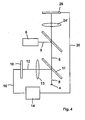
- Fig. 4 shows a third embodiment of a hand-held reader according to the invention, wherein like reference numerals designate the same components, as they have been previously explained with reference to the first two embodiments.
- the structure of the third embodiment substantially corresponds to the structure of the first embodiment.
- receiving means 26 for receiving the reflected light from the storage medium 4 are provided.
- the receiving means 26 thus take the place of the eye of the user of the hand-held reader 2.
- the receiving means 26 are connected via a data line 28 to the display means 14, so that the real image of the storage medium 4 can be displayed directly and observed by the user.
- the magnifying lens 24 has a different focal length than in Fig. 2 the magnifying lens 24 has, so that the image of the surface of the lithogram on the receiving means is improved, that is increased more.
- This technical success can also be achieved by an additional lens which can be swiveled into the beam path in order to present the user with a larger area for searching the lithogram and to provide greater magnification for detecting the microprint or the microimage.
- Fig. 5 shows a fourth embodiment of a hand-held reader according to the invention, wherein like reference numerals designate like components, as have been previously explained with reference to the first three embodiments.
- the structure of the fourth embodiment substantially corresponds to the structure of the second embodiment.
- receiving means 26 are also provided for receiving the light reflected from the storage medium 4.
- the recording means 26 represent an alternative for the eye of the user of the hand-held reader 2.
- For the recording means 26 are coupled via a beam splitter 30, without disturbing the direct beam path for the observing eye.
- the receiving means 26 have an additional magnifying optics 32 and are connected via a data line 28 to the display means 14, so that the real image of the storage medium 4 can be displayed directly and observed by the user.
- the representation of the real image of the point distribution of the lithogram is in Fig. 6c shown.
- the dot distribution of the computer-generated lithogram in the upper left corner as well as a string in micro-writing and a logo as micro-image can be seen.
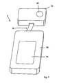
- Fig. 7 shows a further embodiment of the present invention.
- the handheld reader 2 is divided into an optical block 34 and an evaluation block 36, so modular.
- the optical block 34 has in the interior at least the light source and the recording means and possible further components described above.
- the evaluation block 36 has at least the evaluation means and the display means 14.
- the optical block 34 and the evaluation block 36 are connected to each other via an electronic interface 38.
- the electronic interface has, for example, a ribbon cable and corresponding connectors on both sides.
- the standard interfaces for interface cards, such as a Compact Flash card (CF card), are possible here.
- the interface can also be designed optically, for example, as an infrared interface or as a radio interface.
- the optical block 34 and the evaluation block 36 are preferably arranged on a common support (not shown) to form the handheld unit and to be easier to handle.
- one of the two blocks 34 or 36 have an integrally formed therewith holder, in which the respective other block can be used.
- the optical block 34 preferably has the holder.
- the evaluation block 36 is designed as a standard handheld computer. In combination with the optical block 34, which has undergone a lesser change over time, a combination which can be used in the long term is thus created, in which an exchange of the Evaluation unit 36 is possible if the original handheld computer is no longer nachzubeées.
Abstract
Description
Die vorliegende Erfindung betrifft ein Lesegerät zum Auslesen von computergenerierten Lithogrammen.The present invention relates to a reading device for reading computer-generated lithograms.
Computergenerierte Lithogramme sind zweidimensionale Punktmatrizen bevorzugt mit sehr geringen Abmessungen, die aus einzelnen Punkten mit unterschiedlichen optischen Eigenschaften bestehen. Die Lithogramme sind bevorzugt als Hologramme ausgebildet, jedoch können mit den Lithogrammen auch direkt lesbare, also ohne Beugung der auftreffenden Lichtes Mikrotexte oder Mikroabbildungen erzeugt werden.Computer-generated lithograms are two-dimensional point matrices preferred with very small dimensions, which consist of individual points with different optical properties. The lithograms are preferably formed as holograms, but can also be directly readable, ie without diffraction of the incident light micro-texts or micro-images are generated with the lithograms.
Durch Beleuchtung eines computergenerierten Hologramms bspw. mit einer kohärenten elektromagnetischen Welle, insbesondere Lichtwelle durch Beugung in Transmission oder Reflexion Bilder und/oder Daten reproduziert werden. Die unterschiedlichen optischen Eigenschaften der einzelnen Punkte können Reflexionseigenschaften beispielsweise durch Oberflächentopographie, variierende optische Weglängen im Material des Speichermediums (Brechungsindizes) oder Farbwerte des Materials sein.By illumination of a computer-generated hologram, for example, with a coherent electromagnetic wave, in particular light wave by diffraction in transmission or reflection images and / or data can be reproduced. The different optical properties of the individual points can be reflection properties, for example by surface topography, varying optical path lengths in the material of the storage medium (refractive indices) or color values of the material.
Die optischen Eigenschaften der einzelnen Punkte werden von einem Computer berechnet, es handelt sich somit um sogenannte computergenerierte Hologramme (CGH) bzw. allgemein um computergenerierte Lithogramme. Mit Hilfe des fokussierten Schreibstrahls werden während des Schreibens die einzelnen Punkte des Lithogramms in das Material eingeschrieben, wobei der Fokus im Bereich der Oberfläche oder im Material des Speichermediums liegt. Eine Fokussierung bewirkt im Bereich des Fokus eine geringe Einwirkungsfläche auf das Material des Speichermediums, so dass eine Vielzahl von Punkten des Lithogramms in einem kleinen Bereich geschrieben werden kann.The optical properties of the individual points are calculated by a computer, so it is so-called computer-generated holograms (CGH) or generally computer-generated lithographs. With the help of the focused writing beam, the individual points of the lithogram are written into the material during the writing, wherein the focus lies in the area of the surface or in the material of the storage medium. A Focusing causes a small area of influence on the material of the storage medium in the area of the focus, so that a multiplicity of points of the lithogram can be written in a small area.
Durch ein Abscannnen eines intensitätsmodulierten Schreibstrahls entsteht somit eine Fläche mit einer unregelmäßigen Punkteverteilung, das computergenerierte Lithogramm. Dieses kann zum Kennzeichnen, Identifizieren und Individualisieren beliebiger Gegenstände eingesetzt werden.By scanning an intensity-modulated write beam, a surface with an irregular point distribution, the computer-generated lithogram, thus arises. This can be used to identify, identify and individualize any objects.
Bei der Herstellung von Lithogrammen ist eine Auflösung von etwa 25.000 dpi bevorzugt. Außerdem werden bei der computergenerierten Lithographie nur vergleichsweise kleine Flächen beschrieben. Diese sind beispielsweise 1 bis 5 mm2 groß, wobei auch andere Größen möglich sind. Die Genauigkeit des Schreibrasters muss bei einem Lithographen zur Herstellung digitaler Hologramme von beispielsweise 1000 x 1000 Punkten auf einer Fläche von 1 x 1 mm2 etwa ± 0,1 µm in beide orthogonale Richtungen betragen. Darüber hinaus sollte die Schreibgeschwindigkeit etwa 1 Mpixel/s betragen, damit jeweils,ein Lithogramm in einer Zeit von ca. 1s oder weniger geschrieben werden kann.In the production of lithograms, a resolution of about 25,000 dpi is preferred. In addition, only comparatively small areas are described in computer-generated lithography. These are for example 1 to 5 mm 2 in size, although other sizes are possible. The accuracy of the writing pattern in a lithograph for producing digital holograms of, for example, 1000 × 1000 dots on an area of 1 × 1 mm 2 must be about ± 0.1 μm in both orthogonal directions. In addition, the write speed should be about 1 Mpixel / s, so that one lithograph can be written at a time of about 1 s or less.
Die zuvor erläuterten computergenerierten Lithogramme können unterschiedliche Informationen tragen. Zum einen kann das computergenerierte Lithogramm eine holographische Information tragen, die beim Auslesen, also bei der Reproduktion eine direkt lesbare Information (Schrift, Bild, Graphik) wiedergibt. Ebenso kann die ausgelesene Information verschlüsselt, insbesondere digitalisiert sein. Dann enthält das reproduzierte Hologramm beispielsweise eine digitale Matrix ähnlich einem ein- oder zweidimensionalen Barcode. Schließlich kann die Punkteverteilung des computergenerierten Lithogramms an sich eine direkt lesbare Information.mit sehr kleinen Abmessungen aufweisen, beispielsweise eine Mikroschrift oder eine Mikroabbildung. Zum Erkennen ist eine Vergrößerung der direkt lesbaren Mikroschrift notwendig, also ein vom Auslesen des digitalen Hologramms verschiedener Vorgang. Die Mikroschrift und/oder die Mikroabbildung selbst kann wiederum verschlüsselt sein. Beispielsweise kann eine Mikroabbildung selbst eine digitale Information eine ein- oder zweidimensionalen Barcodes darstellen. Selbstverständlich kann ein Lithogramm sowohl eine holographische Information als auch eine direkt lesbare Information beinhalten, also eine Kombination aller dargestellten Möglichkeiten.The computer-generated lithograms explained above can carry different information. On the one hand, the computer-generated lithogram can carry holographic information which, when read out, that is to say during reproduction, reproduces directly readable information (writing, image, graphics). Likewise, the information read out can be encrypted, in particular digitized. Then, for example, the reproduced hologram contains a digital matrix similar to an on or two-dimensional barcode. Finally, the dot distribution of the computer-generated lithogram per se can have directly readable information of very small dimensions, such as a micro-font or a micro-image. To recognize an enlargement of the directly readable micro-writing is necessary, that is a different process from reading the digital hologram. The microwriting and / or the micro-image itself can in turn be encrypted. For example, a microimage may itself represent digital information a one- or two-dimensional barcode. Of course, a lithogram may contain both holographic information and directly readable information, that is, a combination of all the possibilities presented.
Zum Auslesen von computergenerierten Hologrammen sind einfache Handlesegeräte aus dem Stand der Technik bekannt. Diese bedienen sich in der Regel eines Lichtstrahls zum Erzeugen des reproduzierten Hologramms auf einem Schirm.For reading computer-generated holograms simple hand-held readers from the prior art are known. These usually use a light beam to produce the reproduced hologram on a screen.
Aus der
Darüber hinaus sind nicht tragbare, fest installierte Lesegeräte bekannt, die die ausgelesenen Informationen auf einem Computerbildschirm darstellen.In addition, non-portable, fixed readers are known, which display the information read on a computer screen.
Die Technik der Verwendung von computergenerierten Lithogrammen hat inzwischen zu verschiedenen Anwendungen geführt, bei denen einzelne Produkte mit kleinen Labeln versehen werden, auf denen jeweils ein Hologramm eingeschrieben ist. In mehreren Stufen können die verwendeten Lithogramme individualisiert und/oder kodiert sein, wobei beliebige Kombinationen von Mikroschriften und Mikrobildern, direkt lesbare holographische Information und wiederum im Hologramm kodiert hinterlegte, bspw. digitalisierte Informationen miteinander kombiniert werden können. Eine für die Überprüfung der verschiedenen Information mit einem Lesegerät ist bisher nicht möglich gewesen, insbesondere nicht mit einem Handlesegerät.The technique of using computer generated lithograms has in the meantime led to various applications where individual products with small labels be provided on each of which a hologram is inscribed. The lithograms used can be individualized and / or coded in several stages, it being possible to combine any desired combinations of micro-typefaces and microimages, directly readable holographic information and, in turn, coded in the hologram, for example digitized information. One for the verification of the various information with a reader has not been possible, especially not with a handheld reader.
In den Dokumenten
Der vorliegenden Erfindung liegt das technische Problem zugrunde, ein handliches Lesegerät anzugeben, das ein schnelleres und einfacheres Auslesen von kleinen computergenerierten Lithogrammen ermöglicht.The present invention is based on the technical problem of specifying a handy reading device which enables a faster and easier reading of small computer-generated lithograms.
Das zuvor aufgezeigte technische Problem wird erfindungsgemäß durch ein Lesegerät mit den Merkmalen des Anspruchs 1 gelöst. Weitere bevorzugte Ausgestaltungen des Lesegerätes sind in den Unteransprüchen angegeben.The above-indicated technical problem is solved by a reading device with the features of claim 1. Further preferred embodiments of the reading device are specified in the subclaims.
Erfindungsgemäß ist das Lesegerät zum Auslesen von computergenerierten Lithogrammen, die in einem Speichermedium eingeschrieben sind, mit einer Lichtquelle zum Erzeugen eines Lichtstrahls, mit Aufnahmemitteln zum Erfassen der vom Lichtstrahl durch eine Beleuchtung des Lithogramms erzeugten Bilddaten und mit Anzeigemitteln zum Anzeigen der aus den Bilddaten erzeugten Anzeigedaten versehen, wobei sämtliche Komponenten in einer tragbaren Handheld-Einheit zusammengefasst sind.According to the invention, the reading device for reading computer-generated lithograms, which are inscribed in a storage medium, with a light source for generating a light beam, with recording means for Detecting the image data generated by the light beam by illumination of the lithogram and display means for displaying the display data generated from the image data, wherein all the components are combined in a portable handheld unit.
Der Begriff Handheld-Einheit leitet sich aus dem Anwendungsbereich der tragbaren Computer, die auch als Handheld-Computer oder als Personal Digital Assistant (PDA) bezeichnet werden. Auch hier sind sämtliche Computerfunktionen in einem kleinen handlichen Gehäuse angeordnet, so dass ein mobil zu nutzender, nicht an einen festen Standort gebundener Computer entsteht. Das gleiche Prinzip wird bei der vorliegenden Erfindung für das Handlesegerät zum Auslesen von computergenerierten Lithogrammen angewendet. Sämtliche zuvor erwähnten Grundkomponenten - wie auch alle weiteren im Folgenden beschriebenen Komponenten - sind in einer handlichen Einheit, also einer Handheld-Einheit zusammengefasst. Das Lesegerät wird daher im Folgenden auch als Handlesegerät bezeichnet.The term handheld unit is derived from the scope of portable computers, which are also referred to as a handheld computer or as a personal digital assistant (PDA). Again, all computer functions are arranged in a small handy housing, so that a mobile to use, not bound to a fixed location computer arises. The same principle is used in the present invention for the handheld reader for reading computer generated lithograms. All of the above-mentioned basic components - as well as all other components described below - are combined in a handy unit, so a handheld unit. The reader is therefore also referred to below as a handheld reader.
Das Handlesegerät ist dazu geeignet, den Lichtstrahl, der insbesondere als Laserstrahl ausgebildet sein kann, auf das computergenerierte Lithogramm zu richten und das durch Beugungseffekte erzeugte reproduzierte Hologramm und/oder das direkt lesbare Mikrobild aufzunehmen. Dabei wird das Handlesegerät so an das das Lithogramm tragende Objekt, bspw. an eine Verpackung eines Produktes, herangeführt, dass der Lichtstrahl das Lithogramm trifft.The hand-held reader is suitable for directing the light beam, which can be designed in particular as a laser beam, onto the computer-generated lithogram and for recording the reproduced hologram generated by diffraction effects and / or the directly readable microimage. In this case, the hand-held reader is brought to the object carrying the lithogram, for example to a packaging of a product, in such a way that the light beam strikes the lithogram.
Ebenso ist es möglich, bei Objekten mit einer definierten Form eine Halterung vorzusehen, in die das Objekt mit dem Speichermedium oder das Speichermedium selbst eingebracht wird und positioniert wird. Die Halterung ist daher insbesondere für Scheckkarten oder ähnliches geeignet.It is also possible to provide a holder for objects with a defined shape, in which the object with the Storage medium or the storage medium itself is introduced and positioned. The holder is therefore particularly suitable for check cards or the like.
In bevorzugter Weise sind die Aufnahmemittel elektronisch, insbesondere als herkömmlicher CCD-Chip oder als CMOS-Chip ausgebildet. Dadurch wird ein preiswerter Einsatz einer Standardtechnik für das Handlesegerät möglich.Preferably, the recording means are electronic, in particular as a conventional CCD chip or as a CMOS chip. This allows a low-cost use of a standard technique for the handheld reader.
In einer ersten bevorzugten Ausgestaltung der vorliegenden Erfindung sind die Aufnahmemittel direkt mit den Anzeigemitteln verbunden. Die Anzeigemittel können bedarfsweise die Bilddaten als Anzeigedaten darstellen. Dadurch wird in einfacher Weise das Überprüfen des reproduzierten Hologramms ermöglicht, um darin enthaltene direkt lesbare Informationen identifizieren zu können.In a first preferred embodiment of the present invention, the receiving means are connected directly to the display means. The display means may, if necessary, display the image data as display data. This makes it easy to check the reproduced hologram in order to identify directly readable information contained therein.
Als vorteilhafte Anzeigemittel können beispielsweise herkömmliche Displays für mobile Telefone verwendet werden. Auch durch diese Maßnahme kann eine kostengünstige Lösung geschaffen werden.As advantageous display means, for example, conventional displays for mobile phones can be used. Also by this measure, a cost-effective solution can be created.
Bei einer weiteren bevorzugten Ausgestaltung der vorliegenden Erfindung sind Auswertemittel zum Auswerten der Bilddaten und zum Erzeugen der Anzeigedaten vorgesehen. Somit können die von den Aufnahmemitteln erzeugten Bilddaten einer Analyse unterzogen werden.In a further preferred embodiment of the present invention, evaluation means are provided for evaluating the image data and for generating the display data. Thus, the image data generated by the capturing means may be subjected to analysis.
Die Analyse der Bilddaten kann so durchgeführt werden, dass ein oder mehrere Bereiche der Bilddaten ausgewählt und gesondert nacheinander oder parallel als Anzeigedaten auf den Anzeigemitteln dargestellt werden. Dadurch können die Bilddaten vergrößert und/oder in einer speziellen Auswahl dargestellt werden. Ebenso können die gesamten Bilddaten als Anzeigedaten dargestellt werden.The analysis of the image data may be performed such that one or more regions of the image data are selected and displayed separately one after the other or in parallel as display data on the display means. This allows the Image data enlarged and / or displayed in a special selection. Likewise, the entire image data can be displayed as display data.
Eine weitere Analyse der Bilddaten besteht darin, die Anzeigedaten zumindest teilweise aus den Bilddaten abzuleiten. Dieses kann dann zur Anwendung kommen, wenn das reproduzierte Hologramm Daten in kodierter Form enthält. So ist es bekannt, in einem computergenerierten Hologramm eindimensionale oder zweidimensionale Barcodes zu hinterlegen. Diese Barcodes sind dann im reproduzierten Hologramm als dunkle und helle Bereiche zu erkennen. Die in dem Barcode steckenden Informationen können dann nur durch eine weitere Analyse ermittelt werden. Nach der Analyse können diese Informationen dann auf den Anzeigemitteln als lesbarer Text dargestellt werden.Another analysis of the image data is to at least partially derive the display data from the image data. This can be used when the reproduced hologram contains data in coded form. It is thus known to store one-dimensional or two-dimensional barcodes in a computer-generated hologram. These barcodes are then recognized in the reproduced hologram as dark and bright areas. The information contained in the barcode can then only be determined by further analysis. After analysis, this information can then be displayed on the display means as readable text.
Um zwischen der Darstellung des reproduzierten Hologramms und den daraus ermittelten Daten umschalten zu können, sind in bevorzugter Weise Schaltmittel zum Einstellen der Art der Bilddaten vorgesehen. Ebenso kann damit eine Einstellung gewählt werden, bei der die verschiedenen Informationen (Mikrobild, Hologramm, abgeleitete Informationen) gleichzeitig auf den Anzeigemitteln dargestellt werden.In order to be able to switch between the representation of the reproduced hologram and the data determined therefrom, switching means are preferably provided for setting the type of image data. Likewise, a setting can be selected in which the various information (microimage, hologram, derived information) are displayed simultaneously on the display means.
Ebenso können Speichermittel zum Abspeichern einer Mehrzahl von aufgenommenen Bilddaten vorgesehen sein. Somit kann eine Reihe von computergenerierten Hologrammen analysiert werden, ohne dass zwischendurch eine Datenübertragung oder -sicherung erfolgen muss. Dabei reicht es insbesondere aus, wenn nur die direkt lesbaren oder aus einer kodierten Form abgeleiteten Informationen in binärer Form gespeichert werden.Likewise, storage means may be provided for storing a plurality of recorded image data. Thus, a number of computer generated holograms can be analyzed without the need for data transfer or backup in between. In particular, it is sufficient if only the directly readable or from a coded form derived information is stored in binary form.
Das Lesegerät der vorliegenden Erfindung umfasst eine Lupenlinse als Justiermittel. Die Lupenlinse dient einem besseren freihändigen Justieren des Lesegerätes relativ zur Position des Lithogrammes. Der Benutzer des Lesegerätes kann durch die Lupenlinse die Position des Lichtstrahls auf dem Speichermedium bzw. auf dem Objekt in vergrößerter Darstellung direkt beobachten. Wenn der Lichtfleck genau den Bereich erfasst, der vom Lithogramm eingenommen ist, kann der Benutzer einen Auslöser aktivieren, um die Bilddaten von den Aufnahmemitteln festzuhalten.The reader of the present invention comprises a magnifying lens as adjusting means. The magnifying lens serves a better hands-free adjustment of the reader relative to the position of the lithogram. The user of the reading device can directly observe the position of the light beam on the storage medium or on the object in an enlarged view through the magnifying lens. If the light spot accurately detects the area occupied by the lithograph, the user may activate a trigger to capture the image data from the capture means.
Die Lupenlinse kann außerhalb oder innerhalb des Strahlengangs des Lichtstrahls angeordnet sein. Je nach Anordnung wird also der Lichtstrahl durch die Lupenlinse beeinflusst. Daher ist es bei der Anordnung der Lupenlinse im Strahlengang erforderlich, den Lichtstrahl divergent auf die Lupenlinse zu richten, damit hinter der Lupenlinse der Lichtstrahl weitgehend ein paralleles Strahlenbündel darstellt und nicht auf die Beobachtungsebene fokussiert wird.The magnifying lens can be arranged outside or inside the beam path of the light beam. Depending on the arrangement, therefore, the light beam is influenced by the magnifying lens. Therefore, in the arrangement of the magnifying lens in the beam path, it is necessary to divergently direct the light beam onto the magnifying lens, so that behind the magnifying lens, the light beam is largely a parallel beam and is not focused on the observation plane.
Ein Auffinden des kleinen Lithogramms ist alleine mit dem Laserstrahl unter bestimmten Bedingungen nur unter erschwerten Bedingungen möglich. Daher ist es bevorzugt, eine weitere Lichtquelle, insbesondere eine weißes Licht produzierende LED vorzusehen, die den Suchbereich ausleuchtet und ein Erkennen der Position des kleinen Lithogramms erleichtert.Finding the small lithogram is only possible under difficult conditions with the laser beam under certain conditions. Therefore, it is preferred to provide a further light source, in particular a white light-producing LED, which illuminates the search area and facilitates recognition of the position of the small lithogram.
Ebenso ist es möglich, dass die Auswertemittel die fortlaufend von den Aufnahmemitteln erfassten Bilddaten analysieren und bei einer geeigneten Position des reproduzierten Hologramms auf den Aufnahmemitteln die Bilddaten festhalten. Diese Analyse kann anhand von vorgegebenen Informationseinheiten, bspw. ein Erkennungsmuster; innerhalb des reproduzierten Hologramms erfolgen. Sind die Informationseinheiten relativ zur Bildebene der Aufnahmemittel an vorbestimmten Positionen von den Auswertemitteln zu erkennen, werden die Bilddaten festgehalten.Likewise, it is possible for the evaluation means to analyze the image data recorded continuously by the recording means and to record the image data on the recording means at a suitable position of the reproduced hologram. This analysis can be carried out on the basis of predetermined information units, for example a recognition pattern; within the reproduced hologram. If the information units can be recognized by the evaluation means relative to the image plane of the recording means at predetermined positions, the image data are recorded.
Um das Festhalten der Bilddaten dem Benutzer zu signalisieren, ist ein akustischer und/oder optischer Signalgeber vorgesehen. Wird der Signalgeber aktiviert, erkennt der Benutzer, dass das von ihm auszulesende Hologramm erkannt und ggf. gespeichert worden ist.To signal the capture of the image data to the user, an acoustic and / or optical signal generator is provided. If the signal generator is activated, the user recognizes that the hologram to be read by him has been detected and possibly saved.
Anstelle des Auges des Benutzers oder zusätzlich dazu können weitere Aufnahmemittel zum Aufnehmen des vom Speichermedium reflektierten Lichtes vorgesehen sein. Somit wird die Punkteverteilung des computergenerierten Lithogramms an sich, also nicht das reproduzierte Hologramm erfasst, um beispielsweise eine miniaturisierte Abbildung oder Mikroschrift erfassen und auf den Anzeigemitteln darstellen zu können. Der Benutzer kann dann auf den Anzeigemitteln die Position des Lichtstrahls auf dem Objekt bzw. auf dem Speichermedium auf den Anzeigemitteln überprüfen und somit das Handlesegerät justieren.Instead of the user's eye or in addition thereto, further recording means for receiving the light reflected by the storage medium may be provided. Thus, the dot distribution of the computer-generated lithogram per se, so not the reproduced hologram is detected, for example, to capture a miniaturized image or micro-font and display on the display means can. The user can then check on the display means the position of the light beam on the object or on the storage medium on the display means and thus adjust the hand-held reader.
Somit ist es in einem Handlesegerät möglich, die Punkteverteilung mit ggf. vorhandener Mikroschrift oder Mikroabbildungen darzustellen. Dieses gilt auch in Alleinstellung, also ohne dass das Handlesegerät auch in der Lage sein muss, ein reproduziertes Hologramm verarbeiten zu können.Thus, it is possible in a hand-held reader to represent the point distribution with micro-typing or micro-pictures that may be present. This also applies in isolation, that is, without the handheld reader must also be able to process a reproduced hologram can.
Es ist aber bevorzugt, dass das Handlesegerät neben dem Erkennen der Mikroschrift bzw. der Mikroabbildung auch das reproduzierte Hologramm mit darin enthaltenen Informationen und/oder die aus dem reproduzierten Hologramm abgeleiteten Informationen auf den Anzeigemitteln darstellen kann. Die verschiedenen Sicherheitsmerkmale des auf dem Speichermedium eingeschriebenen Lithogramms können somit wahlweise angezeigt werden.However, it is preferred that the handheld reading device can display the reproduced hologram with information contained therein and / or the information derived from the reproduced hologram on the display means in addition to detecting the microprint or the microimage. The various security features of the inscribed on the storage medium lithogram can thus be displayed optionally.
Bei einer weiteren bevorzugten Ausführungsform der vorliegenden Erfindung sind in einem optischen Block zumindest die Lichtquelle und die Aufnahmemittel angeordnet, während in einem Auswerteblock zumindest die Auswertemittel und die Anzeigemittel angeordnet sind. Der optische Block und der Auswerteblock sind über eine elektronische und/oder optische Schnittstelle und/oder eine Funkschnittstelle miteinander verbunden, so dass die von den Aufnahmemitteln erzeugten Bilddaten auf die Auswertemittel übertragen werden können. Durch diesen Aufbau entsteht ein modularer Aufbau, so dass flexibel auf Veränderungen an einem der beiden verschiedenen Funktionsblöcke durch Austausch eines der beiden Blöcke reagiert werden kann.In a further preferred embodiment of the present invention, at least the light source and the recording means are arranged in an optical block, while at least the evaluation means and the display means are arranged in an evaluation block. The optical block and the evaluation block are connected to one another via an electronic and / or optical interface and / or a radio interface, so that the image data generated by the recording means can be transmitted to the evaluation means. This structure results in a modular structure, so that it is possible to respond flexibly to changes to one of the two different functional blocks by exchanging one of the two blocks.
Um trotz der Modularität der beiden beschriebenen Blöcke eine Handheld-Einheit zu bilden, sind der optische Block und der Auswerteblock auf einer gemeinsamen Halterung angeordnet. Diese Halterung kann auch Teil eines der beiden Blöcke, bspw. des optischen Blockes sein, in die der andere Block, bspw. der Auswerteblock aufgesetzt werden kann.In order to form a handheld unit despite the modularity of the two described blocks, the optical block and the evaluation block are arranged on a common support. This holder can also be part of one of the two blocks, for example the optical block, into which the other block, for example the evaluation block, can be placed.
Der modulare Aufbau kommt insbesondere dem Umstand zugute, dass der Auswerteblock als serienmäßiger Handheld-Computer (PDA) ausgebildet ist. Da die technische Entwicklung auf diesem Gebiet sehr schnell verläuft und die Produktzyklen sehr kurz sind, kann als Ersatz für einen beschädigten Auswerteblock ein aktuelles neueres Modell eines Handheld-Computers eingesetzt werden. Die Schnittstellen sind daher in bevorzugter Weise ebenfalls standardisiert, um die Austauschbarkeit der beiden Blöcke zueinander zu gewährleisten.The modular design is particularly beneficial to the fact that the evaluation block is designed as a standard handheld computer (PDA). Since the technical development in this area is very fast and the product cycles are very short, a current newer model of a handheld computer can be used as a replacement for a damaged evaluation block. The interfaces are therefore also standardized in a preferred manner, in order to ensure the interchangeability of the two blocks to each other.
Im folgenden wird die Erfindung anhand von Ausführungsbeispielen näher erläutert, wobei auf die beigefügte Zeichnung Bezug genommen wird. In der Zeichnung zeigen
- Fig. 1
- ein Ausführungsbeispiel eines erfindungsgemäßen Handlesegerätes in perspektivischer Darstellung,
- Fig. 2
- ein erstes Ausführungsbeispiel des Aufbaus der Komponenten des Handlesegerätes in einer schematischen Darstellung,
- Fig. 3
- ein zweites Ausführungsbeispiel des Aufbaus der Komponenten des Handlesegerätes in einer schematischen Darstellung,
- Fig. 4
- ein drittes Ausführungsbeispiel des Aufbaus der Komponenten des Handlesegerätes in einer schematischen Darstellung,
- Fig. 5
- ein viertes Ausführungsbeispiel des Aufbaus der Komponenten des Handlesegerätes in einer schematischen Darstellung,
- Fig. 6a-c
- Darstellungen des Handlesegerätes mit unterschiedlichen bildlichen Inhalten der Anzeigemittel und
- Fig. 7
- ein Ausführungsbeispiel eines erfindungsgemäßen Handlesegerätes mit modularem Aufbau in perspektivischer Darstellung.
- Fig. 1
- An embodiment of a hand-held reader according to the invention in a perspective view,
- Fig. 2
- A first embodiment of the construction of the components of the hand-held reader in a schematic representation,
- Fig. 3
- A second embodiment of the construction of the components of the hand-held reader in a schematic representation,
- Fig. 4
- A third embodiment of the construction of the components of the hand-held reader in a schematic representation,
- Fig. 5
- A fourth embodiment of the construction of the components of the hand-held reader in a schematic representation,
- Fig. 6a-c
- Representations of the hand-held reader with different visual content of the display means and
- Fig. 7
- An embodiment of a hand-held reader according to the invention with a modular structure in a perspective view.
Der Aufbau weist als Basiskomponenten eine Lichtquelle 6 zum Erzeugen eines Licht- bzw. Laserstrahls 8, Aufnahmemittel 10 zum Erfassen der Bilddaten des vom Lichtstrahl 8 von der Punkteverteilung des Lithogramms reproduzierten Hologramms (Strahlengang 12) und Anzeigemittel 14 zum Anzeigen der aus den Bilddaten erzeugten Anzeigedaten auf. Die Aufnahmemittel 10 sind über eine Datenleitung 16 mit den Anzeigemitteln 14 verbunden sind. Im in
Sämtliche Komponenten 6, 10 und 14 (sowie ebenfalls weitere nachfolgend beschriebenen Komponenten des Lesegerätes) sind in einer tragbaren Handheld-Einheit zusammengefasst. Dieses ist insbesondere in
Die in
Bei dem in
Zusätzlich zu dem bereits beschriebenen Aufbau sind beim zweiten Ausführungsbeispiel Auswertemittel 20, die über Datenleitungen 16 mit den Aufnahmemitteln 10 und den Anzeigemitteln 14 verbunden sind, vorgesehen. Mit den Auswertemitteln 20 werden die Bilddaten ausgewertet und die Anzeigedaten erzeugt. Die Auswertemittel 20 sind elektronisch und bestehen aus mindestens einem Mikroprozessor, Speichermitteln sowie aus Ein- und Ausgangsschnittstellen. Die Speichermittel dienen dabei insbesondere zum Abspeichern einer Mehrzahl von aufgenommenen Bilddaten oder Auswertedaten. Auch hier kann auf herkömmliche und somit preiswerte Technik zurückgegriffen werden, beispielsweise können als Anzeigemittel 14 und als Auswertemittel 20 ein Handheld-Computer (PDA) verwendet werden.In addition to the structure already described, in the second exemplary embodiment evaluation means 20, which are connected via
Mit Hilfe der Auswertemittel 20 ist es möglich, die Bilddaten vor einem Anzeigen aufzubereiten. Dabei können zum einen die Anzeigedaten zumindest einen Teil der Bilddaten, vorzugsweise die gesamten Bilddaten umfassen. Zum anderen können die Anzeigedaten zumindest einen Teil der aus den Bilddaten abgeleiteten Daten darstellen. Mit anderen Worten können die Anzeigedaten einerseits ein oder mehrere Teile der von den Aufnahmemitteln 10 aufgenommenen Bilddaten sein. Andererseits können die Anzeigedaten die Informationen enthalten, die durch die Auswertung der in dem reproduzierten Hologramm enthaltenen Informationen erzeugt werden. Hierzu sei erneut auf ein Abbild eines ein- oder zweidimensionalen Barcodes hingewiesen, dessen Information erst nach einer Auswertung des Barcodemusters erhalten werden können.With the aid of the evaluation means 20, it is possible to prepare the image data before displaying. In this case, on the one hand, the display data may comprise at least part of the image data, preferably the entire image data. On the other hand, the display data can represent at least part of the data derived from the image data. In other words, the display data on the one hand may be one or more parts of the image data recorded by the recording means 10. On the other hand, the display data may include the information generated by the evaluation of the information contained in the reproduced hologram. For this purpose, reference is again made to an image of a one-dimensional or two-dimensional barcode whose information can only be obtained after an evaluation of the barcode pattern.
Die beiden unterschiedlichen Informationsgehalte der auf den Anzeigemitteln 14 gezeigten Informationen sind in den
Weiterhin ist in
Wie in den
Dazu kann - nicht in den Figuren dargestellt - eine weitere Lichtquelle vorgesehen sein, die den Bereich des Lithogramms ausleuchtet, insbesondere mit weißem Licht. Dadurch wird die Erkennbarkeit des Lithogramms verbessert. Die Lichtquelle kann als LED ausgebildet sein. Zusätzlich kann auch noch ein Ziel- oder Fadenkreuz ausgeleuchtet werden, dessen reflektiertes Abbild vom Betrachter bzw. von den unten erläuterten weiteren Aufnahmemitteln erfasst werden kann.For this purpose - not shown in the figures - a further light source can be provided, which illuminates the area of the lithogram, in particular with white light. This improves the recognizability of the lithogram. The light source can be designed as an LED. In addition, it is also possible to illuminate a target or crosshair whose reflected image can be detected by the viewer or by the other recording means explained below.
Die Lupenlinse 24 ist in
In
Eine weitere Hilfe beim Justieren des Handlesegerätes relativ zum Speichermedium 4 besteht darin, dass die Auswertemittel 20 gemäß
Des weiteren kann ein akustischer und/oder optischer Signalgeber vorgesehen sein, der dann aktiviert wird, wenn die Auswertemittel 20 die optimale Justierung festgestellt haben. Der Benutzer wird also umgehend darüber informiert, wenn die Reproduktion eines Hologramms erfolgreich aufgenommen worden ist.Furthermore, an acoustic and / or optical signal generator can be provided, which is then activated when the evaluation means 20 have determined the optimum adjustment. The user will be informed immediately when the reproduction of a hologram has been successfully recorded.
Beim dritten Ausführungsbeispiel sind Aufnahmemittel 26 zum Aufnehmen des vom Speichermedium 4 reflektierten Lichtes vorgesehen. Die Aufnahmemittel 26 treten also an die Stelle des Auges des Benutzers des Handlesegerätes 2. Die Aufnahmemittel 26 sind über eine Datenleitung 28 mit den Anzeigemitteln 14 verbunden, so dass das reale Bild des Speichermediums 4 direkt angezeigt und vom Benutzer beobachtet werden kann.In the third embodiment, receiving means 26 for receiving the reflected light from the
Bei der Ausgestaltung der Optik ist dann zu berücksichtigen, dass die Lupenlinse 24' eine andere Brennweite als in
Dieser technische Erfolg kann auch durch eine in den Strahlengang einschwenkbare zusätzliche Linse erreicht werden, um dem Benutzer zum einen für ein Suchen des Lithogramms eine größere Fläche darzustellen und zum anderen zum Erkennen der Mikroschrift bzw. des Mikrobildes eine stärkere Vergrößerung zu bieten.This technical success can also be achieved by an additional lens which can be swiveled into the beam path in order to present the user with a larger area for searching the lithogram and to provide greater magnification for detecting the microprint or the microimage.
Beim vierten Ausführungsbeispiel sind ebenfalls Aufnahmemittel 26 zum Aufnehmen des vom Speichermedium 4 reflektierten Lichtes vorgesehen. Die Aufnahmemittel 26 stellen eine Alternative für das Auge des Benutzers des Handlesegerätes 2 dar. Denn die Aufnahmemittel 26 sind über einen Strahlteiler 30 angekoppelt, ohne den direkten Strahlengang für das beobachtende Auge zu stören. Die Aufnahmemittel 26 weisen eine zusätzliche vergrößernde Optik 32 auf und sind über eine Datenleitung 28 mit den Anzeigemitteln 14 verbunden, so dass das reale Bild des Speichermediums 4 direkt angezeigt und vom Benutzer beobachtet werden kann.In the fourth embodiment, receiving means 26 are also provided for receiving the light reflected from the
Die Darstellung des realen Bildes der Punkteverteilung des Lithogramms ist in
Je nach Aufbau des dritten oder vierten Ausführungsbeispiels können bei der Beobachtung des Hologramms auch die in den
Der optische Block 34 weist im Inneren zumindest die Lichtquelle und die Aufnahmemittel sowie mögliche weitere zuvor beschriebene Komponenten auf. Der Auswerteblock 36 weist zumindest die Auswertemittel und die Anzeigemittel 14 auf. Der optische Block 34 und der Auswerteblock 36 sind über eine elektronische Schnittstelle 38 miteinander verbunden. Die elektronische Schnittstelle weist bspw. ein Flachbandkabel und entsprechende Steckverbindungen auf beiden Seiten auf. Hierbei sind die Standardschnittstellen für Schnittstellenkarten, beispielsweise eine Compact Flash Karte (CF-Steckkarte) möglich. Die Schnittstelle kann auch optisch bspw. als Infrarotschnittstelle oder als Funkschnittstelle ausgebildet sein.The
Der optische Block 34 und der Auswerteblock 36 sind in bevorzugter Weise auf einer gemeinsamen Halterung (nicht dargestellt) angeordnet, um die Handheld-Einheit zu bilden und leichter handhabbar zu sein. Dabei kann eine der beiden Blöcke 34 oder 36 eine integral damit ausgebildete Halterung aufweisen, in die der jeweils andere Block eingesetzt werden kann. Bevorzugt weist dabei der optische Block 34 die Halterung auf.The
Denn es ist bevorzugt, dass der Auswerteblock 36 als serienmäßiger Handheld-Computer ausgebildet ist. Damit wird in Kombination mit dem einem geringeren zeitlichen Wandel unterzogenen optischen Block 34 eine langfristig nutzbare Kombination geschaffen, bei der auch ein Austausch der Auswerteinheit 36 dann möglich ist, wenn der ursprüngliche Handheld-Computer nicht mehr nachzubeschaffen ist.Because it is preferred that the
Claims (15)
- Reader for reading computer-generated lithograms which are written into a storage medium (4),- having a light source (6) for generating a light beam (8),- having recording means (10) for acquiring the image data generated by the light beam (8) by illuminating the lithogram,- having display means (14) for displaying the display data generated from the image data, and- the recording means (10) being suitable for acquiring the image data of a hologram reproduced by the light beam (8),- all the components being combined in a portable handheld unit,
characterized in that- the reader has a magnifying lens (24) as adjusting means for the free-handed adjustment of the reader relative to the position of the lithogram. - Reader according to Claim 1, characterized in that the recording means (10; 26) are electronic, in particular are formed as a CMOS chip or as a CCD chip.
- Reader according to Claim 1 or 2, characterized in that the display means (14) is formed as a flat monitor, in particular as a display of a mobile telephone or as a monitor of a handheld computer.
- Reader according to one of Claims 1 to 3, characterized in that evaluation means (20) are provided for evaluating the image data and for generating the display data.
- Reader according to Claim 4, characterized in that switching means are provided for setting the type of image data.
- Reader according to one of Claims 1 to 5, characterized in that storage means are provided for storing a plurality of items of recorded image data.
- Reader according to one of Claims 1 to 6, characterized in that the magnifying lens (24) is arranged outside the beam path of the light beam (8).
- Reader according to one of Claims 1 to 6, characterized in that the magnifying lens (24) is arranged inside the beam path of the light beam (8).
- Reader according to one of Claims 1 to 8, characterized in that a light source is provided for illuminating the lithogram, in particular an LED, preferably an LED that generates white light.
- Reader according to one of Claims 4 to 9, characterized in that the evaluation means (20) are formed such that the image data acquired continuously by the recording means are analyzed by the evaluation means (20) and, given a suitable position of the reproduced hologram, the image data are recorded by the evaluation means (20) on the recording means (10).
- Reader according to Claim 10, characterized in that an acoustic and/or optical signal generator is provided.
- Reader according to one of Claims 1 to 11, characterized in that the recording means (26) are provided for recording the light reflected from the storage medium (4).
- Reader according to Claim 12, characterized in that an additional lens that offers the user a higher magnification and can be pivoted into the beam path is provided.
- Reader according to one of Claims 1 to 13, characterized in that- at least the light source (6) and the recording means (10) are arranged in an optical block (34),- at least the evaluation means (20) and the display means (14) are arranged in an evaluation block (36), and- the optical block (34) and the evaluation block (36) are connected to each other via an electronic and/or optical interface (38).
- Reader according to Claim 14, characterized in that the optical block (34) and the evaluation block (36) are arranged on a common holder.
Applications Claiming Priority (2)
| Application Number | Priority Date | Filing Date | Title |
|---|---|---|---|
| DE202004007636U DE202004007636U1 (en) | 2004-05-10 | 2004-05-10 | Reading device for reading computer-generated lithographs |
| PCT/EP2005/004859 WO2005111913A1 (en) | 2004-05-10 | 2005-05-04 | Reading device for reading out computer-generated lithograms |
Publications (2)
| Publication Number | Publication Date |
|---|---|
| EP1745407A1 EP1745407A1 (en) | 2007-01-24 |
| EP1745407B1 true EP1745407B1 (en) | 2011-03-02 |
Family
ID=32731466
Family Applications (1)
| Application Number | Title | Priority Date | Filing Date |
|---|---|---|---|
| EP05737397A Expired - Fee Related EP1745407B1 (en) | 2004-05-10 | 2005-05-04 | Reading device for reading out computer-generated lithograms |
Country Status (4)
| Country | Link |
|---|---|
| US (2) | US7475820B2 (en) |
| EP (1) | EP1745407B1 (en) |
| DE (2) | DE202004007636U1 (en) |
| WO (1) | WO2005111913A1 (en) |
Families Citing this family (11)
| Publication number | Priority date | Publication date | Assignee | Title |
|---|---|---|---|---|
| DE202004019513U1 (en) * | 2004-12-15 | 2005-02-17 | Tesa Scribos Gmbh | Hologram readout device especially for computer generated digital holograms, has hologram positioned in front of second lens as seen in radiation direction |
| EP1826632B1 (en) | 2006-02-22 | 2015-12-30 | tesa scribos GmbH | Method for calculating computer generated holograms on an non-planar surface |
| CN101477313B (en) | 2006-04-04 | 2013-04-17 | 特萨斯克里伯斯有限公司 | Device and method for microstructuring a storage medium and storage medium comprising a microstructured region |
| DE102006032538A1 (en) | 2006-04-04 | 2007-10-11 | Tesa Scribos Gmbh | Storage medium with a security feature and method for producing a storage medium with a security feature |
| DE102006015604A1 (en) * | 2006-04-04 | 2007-10-11 | Tesa Scribos Gmbh | Storage medium, preferably for a carrier, and reading device and method for reading such a storage medium |
| DE102006032234A1 (en) | 2006-07-12 | 2008-01-17 | Tesa Scribos Gmbh | Method for applying a security feature to a security document and security document with a security feature |
| DE102007004857A1 (en) | 2007-01-31 | 2008-08-07 | Tesa Scribos Gmbh | Data medium i.e. label, for labeling e.g. credit card, has storage medium including adhesive layer that is partially hardened, where adhesive layer includes recess in area of storage medium for recording |
| DE102007006120A1 (en) | 2007-02-02 | 2008-08-07 | Tesa Scribos Gmbh | Storage medium with an optically changeable storage layer |
| DE102007006119A1 (en) | 2007-02-02 | 2008-08-14 | Tesa Scribos Gmbh | data storage |
| US20110010283A1 (en) * | 2009-07-09 | 2011-01-13 | Eddie Williams | E-card |
| DE102009040112B4 (en) | 2009-09-04 | 2021-03-04 | Tesa Scribos Gmbh | Label web with a plurality of labels |
Family Cites Families (13)
| Publication number | Priority date | Publication date | Assignee | Title |
|---|---|---|---|---|
| US3946370A (en) * | 1972-11-02 | 1976-03-23 | U.S. Philips Corporation | Method of making light-dot distribution for the holographic storage of binary information with the aid of electronically controlled switching masks |
| US3906448A (en) * | 1974-08-01 | 1975-09-16 | Rca Corp | Fault detection facilitating means for card reader of identification card reading system |
| US4149269A (en) * | 1976-09-29 | 1979-04-10 | Ricoh Co., Ltd. | Holographic reading apparatus with an area identification and density reference scan |
| US5294782A (en) * | 1991-09-27 | 1994-03-15 | Khyber Technologies Corporation | Integrated portable device for point of sale transactions |
| US5432329A (en) * | 1992-02-07 | 1995-07-11 | American Bank Note Holographics | Automated holographic optical recognition and decoding system for verification |
| US5821523A (en) * | 1992-03-12 | 1998-10-13 | Bunte; Alan G. | Combined code reader and digital camera using a common photodetector |
| US5444225A (en) * | 1992-03-31 | 1995-08-22 | Dai Nippon Printing Co., Ltd. | System and process for reading hologram code, hologram and card containing hologram |
| US5306899A (en) * | 1992-06-12 | 1994-04-26 | Symbol Technologies, Inc. | Authentication system for an item having a holographic display using a holographic record |
| US6616043B2 (en) * | 1998-04-07 | 2003-09-09 | Victor Zazzu | Multi sensor information reader |
| US6177683B1 (en) | 1998-11-25 | 2001-01-23 | C2It, Inc. | Portable viewer for invisible bar codes |
| US6263104B1 (en) * | 1998-12-31 | 2001-07-17 | Mcgrew Stephen P. | Method and apparatus for reading and verifying holograms |
| JP2002074261A (en) * | 2000-08-28 | 2002-03-15 | Denso Corp | Information code reader |
| KR20020009379A (en) | 2000-10-13 | 2002-02-01 | 신영철 | The wireless barcode scanner with capability of scanning lcd barcode |
-
2004
- 2004-05-10 DE DE202004007636U patent/DE202004007636U1/en not_active Expired - Lifetime
- 2004-08-02 US US10/910,249 patent/US7475820B2/en not_active Expired - Fee Related
-
2005
- 2005-05-04 WO PCT/EP2005/004859 patent/WO2005111913A1/en not_active Application Discontinuation
- 2005-05-04 DE DE502005011031T patent/DE502005011031D1/en active Active
- 2005-05-04 EP EP05737397A patent/EP1745407B1/en not_active Expired - Fee Related
-
2008
- 2008-12-02 US US12/326,554 patent/US8167206B2/en not_active Expired - Fee Related
Also Published As
| Publication number | Publication date |
|---|---|
| US20090134224A1 (en) | 2009-05-28 |
| US8167206B2 (en) | 2012-05-01 |
| US20050247788A1 (en) | 2005-11-10 |
| DE202004007636U1 (en) | 2004-07-15 |
| EP1745407A1 (en) | 2007-01-24 |
| WO2005111913A1 (en) | 2005-11-24 |
| US7475820B2 (en) | 2009-01-13 |
| DE502005011031D1 (en) | 2011-04-14 |
Similar Documents
| Publication | Publication Date | Title |
|---|---|---|
| EP1745407B1 (en) | Reading device for reading out computer-generated lithograms | |
| DE69909997T2 (en) | INDIVIDUALIZED FINGERPRINT SAMPLE | |
| DE69725016T2 (en) | PORTABLE DATA COLLECTION DEVICE WITH VISIBILITY DEVICE | |
| DE69631670T2 (en) | MANUAL SCAN WITH ROTATIONAL POSITION DETECTOR | |
| DE102005039197B4 (en) | Device for reading optical information | |
| DE102005054396A1 (en) | Device and method for projection of image with multi-mirror elements, comprising tiltable individual mirrors | |
| EP0675466A2 (en) | Method and device for recognizing or checking objects | |
| DE102005028410A1 (en) | Device for optically reading information | |
| DE19957390A1 (en) | Individualization system for an object | |
| DE102005040056B4 (en) | Device for optically reading information | |
| EP1195045B1 (en) | Automatic authentification of documents protected with security features | |
| DE60026301T2 (en) | DEVICE AND METHOD FOR IDENTIFYING, CODING, STORING AND FINDING IMAGES BY THEIR SHAPE | |
| WO2007039054A1 (en) | Process for generating display images from acquired recorded images, and means for carrying out the process | |
| BE1029678B1 (en) | Telephoto lens for compact, long-range barcode readers | |
| WO2007107251A1 (en) | Method and apparatus for optically reading information | |
| EP3693934B1 (en) | Imaging system for capturing a feature of an identification document | |
| EP1360556A1 (en) | Double hologram | |
| DE102008007731B4 (en) | Method and device for identifying and authenticating objects | |
| EP2619712B1 (en) | Method and apparatus for detecting and/or assessing three-dimensional elevated structures on a surface of a document | |
| DE19837428C2 (en) | Arrangement for optically capturing fingerprints | |
| DE102012003241A1 (en) | Device for automatically checking e.g. value and/or security document, has support surface and holding element rotatable relative to each other about rotation axle such that checking devices cover portion of support surface in succession | |
| DE102004053071B4 (en) | Devices for recording or reading a coded hologram | |
| DE102008052248B4 (en) | Method and device for checking lens structures | |
| DE60033260T2 (en) | Position measuring device and method | |
| DE60124283T2 (en) | Optical data carrier with an optical diffraction-based code, and associated reader |
Legal Events
| Date | Code | Title | Description |
|---|---|---|---|
| PUAI | Public reference made under article 153(3) epc to a published international application that has entered the european phase |
Free format text: ORIGINAL CODE: 0009012 |
|
| 17P | Request for examination filed |
Effective date: 20061009 |
|
| AK | Designated contracting states |
Kind code of ref document: A1 Designated state(s): DE ES FR GB IT |
|
| 17Q | First examination report despatched |
Effective date: 20070302 |
|
| DAX | Request for extension of the european patent (deleted) | ||
| RBV | Designated contracting states (corrected) |
Designated state(s): DE ES FR GB IT |
|
| GRAP | Despatch of communication of intention to grant a patent |
Free format text: ORIGINAL CODE: EPIDOSNIGR1 |
|
| GRAS | Grant fee paid |
Free format text: ORIGINAL CODE: EPIDOSNIGR3 |
|
| GRAA | (expected) grant |
Free format text: ORIGINAL CODE: 0009210 |
|
| AK | Designated contracting states |
Kind code of ref document: B1 Designated state(s): DE ES FR GB IT |
|
| REG | Reference to a national code |
Ref country code: GB Ref legal event code: FG4D Free format text: NOT ENGLISH |
|
| REF | Corresponds to: |
Ref document number: 502005011031 Country of ref document: DE Date of ref document: 20110414 Kind code of ref document: P |
|
| REG | Reference to a national code |
Ref country code: DE Ref legal event code: R096 Ref document number: 502005011031 Country of ref document: DE Effective date: 20110414 |
|
| PG25 | Lapsed in a contracting state [announced via postgrant information from national office to epo] |
Ref country code: ES Free format text: LAPSE BECAUSE OF FAILURE TO SUBMIT A TRANSLATION OF THE DESCRIPTION OR TO PAY THE FEE WITHIN THE PRESCRIBED TIME-LIMIT Effective date: 20110613 |
|
| PLBE | No opposition filed within time limit |
Free format text: ORIGINAL CODE: 0009261 |
|
| STAA | Information on the status of an ep patent application or granted ep patent |
Free format text: STATUS: NO OPPOSITION FILED WITHIN TIME LIMIT |
|
| 26N | No opposition filed |
Effective date: 20111205 |
|
| REG | Reference to a national code |
Ref country code: DE Ref legal event code: R097 Ref document number: 502005011031 Country of ref document: DE Effective date: 20111205 |
|
| PG25 | Lapsed in a contracting state [announced via postgrant information from national office to epo] |
Ref country code: IT Free format text: LAPSE BECAUSE OF FAILURE TO SUBMIT A TRANSLATION OF THE DESCRIPTION OR TO PAY THE FEE WITHIN THE PRESCRIBED TIME-LIMIT Effective date: 20110302 |
|
| REG | Reference to a national code |
Ref country code: FR Ref legal event code: PLFP Year of fee payment: 12 |
|
| REG | Reference to a national code |
Ref country code: FR Ref legal event code: PLFP Year of fee payment: 13 |
|
| REG | Reference to a national code |
Ref country code: FR Ref legal event code: PLFP Year of fee payment: 14 |
|
| PGFP | Annual fee paid to national office [announced via postgrant information from national office to epo] |
Ref country code: FR Payment date: 20200522 Year of fee payment: 16 |
|
| PGFP | Annual fee paid to national office [announced via postgrant information from national office to epo] |
Ref country code: GB Payment date: 20200527 Year of fee payment: 16 |
|
| PGFP | Annual fee paid to national office [announced via postgrant information from national office to epo] |
Ref country code: DE Payment date: 20210520 Year of fee payment: 17 |
|
| REG | Reference to a national code |
Ref country code: DE Ref legal event code: R081 Ref document number: 502005011031 Country of ref document: DE Owner name: SCRIBOS GMBH, DE Free format text: FORMER OWNER: TESA SCRIBOS GMBH, 69126 HEIDELBERG, DE |
|
| GBPC | Gb: european patent ceased through non-payment of renewal fee |
Effective date: 20210504 |
|
| REG | Reference to a national code |
Ref country code: DE Ref legal event code: R081 Ref document number: 502005011031 Country of ref document: DE Owner name: SCRIBOS GMBH, DE Free format text: FORMER OWNER: SCRIBOS GMBH, 69126 HEIDELBERG, DE |
|
| PG25 | Lapsed in a contracting state [announced via postgrant information from national office to epo] |
Ref country code: GB Free format text: LAPSE BECAUSE OF NON-PAYMENT OF DUE FEES Effective date: 20210504 |
|
| PG25 | Lapsed in a contracting state [announced via postgrant information from national office to epo] |
Ref country code: FR Free format text: LAPSE BECAUSE OF NON-PAYMENT OF DUE FEES Effective date: 20210531 |
|
| REG | Reference to a national code |
Ref country code: DE Ref legal event code: R119 Ref document number: 502005011031 Country of ref document: DE |
|
| PG25 | Lapsed in a contracting state [announced via postgrant information from national office to epo] |
Ref country code: DE Free format text: LAPSE BECAUSE OF NON-PAYMENT OF DUE FEES Effective date: 20221201 |