EP1744948B1 - Disc brake caliper - Google Patents
Disc brake caliper Download PDFInfo
- Publication number
- EP1744948B1 EP1744948B1 EP04745180A EP04745180A EP1744948B1 EP 1744948 B1 EP1744948 B1 EP 1744948B1 EP 04745180 A EP04745180 A EP 04745180A EP 04745180 A EP04745180 A EP 04745180A EP 1744948 B1 EP1744948 B1 EP 1744948B1
- Authority
- EP
- European Patent Office
- Prior art keywords
- caliper
- brake
- bridge
- calipers
- disc
- Prior art date
- Legal status (The legal status is an assumption and is not a legal conclusion. Google has not performed a legal analysis and makes no representation as to the accuracy of the status listed.)
- Not-in-force
Links
Images


Classifications
-
- B—PERFORMING OPERATIONS; TRANSPORTING
- B62—LAND VEHICLES FOR TRAVELLING OTHERWISE THAN ON RAILS
- B62L—BRAKES SPECIALLY ADAPTED FOR CYCLES
- B62L3/00—Brake-actuating mechanisms; Arrangements thereof
- B62L3/02—Brake-actuating mechanisms; Arrangements thereof for control by a hand lever
- B62L3/023—Brake-actuating mechanisms; Arrangements thereof for control by a hand lever acting on fluid pressure systems
-
- F—MECHANICAL ENGINEERING; LIGHTING; HEATING; WEAPONS; BLASTING
- F16—ENGINEERING ELEMENTS AND UNITS; GENERAL MEASURES FOR PRODUCING AND MAINTAINING EFFECTIVE FUNCTIONING OF MACHINES OR INSTALLATIONS; THERMAL INSULATION IN GENERAL
- F16D—COUPLINGS FOR TRANSMITTING ROTATION; CLUTCHES; BRAKES
- F16D55/00—Brakes with substantially-radial braking surfaces pressed together in axial direction, e.g. disc brakes
- F16D2055/0004—Parts or details of disc brakes
- F16D2055/0008—Brake supports
- F16D2055/0012—Brake supports integral with vehicle suspension
-
- F—MECHANICAL ENGINEERING; LIGHTING; HEATING; WEAPONS; BLASTING
- F16—ENGINEERING ELEMENTS AND UNITS; GENERAL MEASURES FOR PRODUCING AND MAINTAINING EFFECTIVE FUNCTIONING OF MACHINES OR INSTALLATIONS; THERMAL INSULATION IN GENERAL
- F16D—COUPLINGS FOR TRANSMITTING ROTATION; CLUTCHES; BRAKES
- F16D55/00—Brakes with substantially-radial braking surfaces pressed together in axial direction, e.g. disc brakes
- F16D2055/0004—Parts or details of disc brakes
- F16D2055/0016—Brake calipers
- F16D2055/002—Brake calipers assembled from a plurality of parts
-
- F—MECHANICAL ENGINEERING; LIGHTING; HEATING; WEAPONS; BLASTING
- F16—ENGINEERING ELEMENTS AND UNITS; GENERAL MEASURES FOR PRODUCING AND MAINTAINING EFFECTIVE FUNCTIONING OF MACHINES OR INSTALLATIONS; THERMAL INSULATION IN GENERAL
- F16D—COUPLINGS FOR TRANSMITTING ROTATION; CLUTCHES; BRAKES
- F16D65/00—Parts or details
- F16D65/02—Braking members; Mounting thereof
- F16D2065/13—Parts or details of discs or drums
- F16D2065/134—Connection
- F16D2065/1348—Connection resilient
-
- F—MECHANICAL ENGINEERING; LIGHTING; HEATING; WEAPONS; BLASTING
- F16—ENGINEERING ELEMENTS AND UNITS; GENERAL MEASURES FOR PRODUCING AND MAINTAINING EFFECTIVE FUNCTIONING OF MACHINES OR INSTALLATIONS; THERMAL INSULATION IN GENERAL
- F16D—COUPLINGS FOR TRANSMITTING ROTATION; CLUTCHES; BRAKES
- F16D2121/00—Type of actuator operation force
- F16D2121/02—Fluid pressure
Definitions
- the subject of the present invention is a disc brake caliper, particularly for a disc brake for bicycles.
- disc brakes which are provided with so-called fixed brake calipers which are usually mounted on a portion of the bicycle frame, for example, on one or both blades of the fork.
- Normally, fixed brake calipers are constituted by two half-calipers. Each half-caliper has a body suitable for facing the brake disc and a portion projecting towards the median plane of the brake disc. The two projecting portions of the two half calipers are joined along that plane to form a bridge which connects the two half calipers mechanically and hydraulically. Each body which faces the brake disc houses a piston suitable for acting on respective pads.
- the caliper is fixed to the blade of the fork by means of two screws. These screws generally extend through suitable slots formed in the caliper body and are engaged in a corresponding number of threaded holes formed in a support fixed firmly to the blade of the fork. Conventionally, once the fixing screws of the brake caliper have been fitted, they are arranged in a manner such that their axes are parallel to the axis of rotation of the brake disc. This conventional fixing is therefore known as "axial" fixing.
- Brake calipers in which, once the fixing screws are fitted, they are arranged in a manner such that their axes are substantially parallel to the plane defined by the brake disc are also known and are particularly highly valued.
- This fixing is known as "radial” fixing although, strictly speaking, the direction adopted by the axes of the screws is not always strictly radial relative to the brake disc but is often purely parallel to a radial axis.
- This type of fixing will be referred to below as “radial” fixing in accordance with the terminology that has become established in the field.
- the object of the present invention is to devise and provide a disc brake caliper for bicycles which overcomes the disadvantages discussed above with reference to the prior art.
- the task of the present invention is to provide a brake caliper for bicycles which has limited size and weight.
- a brake caliper is generally indicated 10.
- the caliper 10 is mounted on a support 1 fixed firmly to a portion of the bicycle frame, for example, to a blade 2 of the fork.
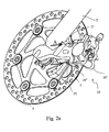
- the support 1 may equally well be formed integrally with the blade 2 or welded thereto (see, for example, Figure 2a ) or may be fixed firmly thereto by means of screws (see, for example, Figure 2b ).
- the support 1 is shaped in a manner such that, once the caliper 10 is mounted on the support 1, the caliper 10 is arranged astride the brake disc 3. More precisely, the caliper 10 is composed of two half calipers 10' and 10" which are arranged on the axially inner side, that is, the side facing the wheel, and on the axially outer side of the brake disc 3, respectively.
- Each of the two half calipers 10' and 10" comprises a radially inner portion 101 which is intended to be disposed beside the brake disc 3 and a radially outer portion 102 (see Figure 6 ). It is thus intended to define unambiguously that which is radially inner as that which is closer to the axis of rotation of the brake disc and that which is radially outer as that which is farther from the axis of rotation of the brake disc.
- At least one projecting portion 110 extends from the radially outer portion 102 of at least one of the two half calipers 10' or 10" towards the other side of the disc so as to meet the corresponding radially outer portion 102 of the other half caliper along a contact surface c-c.
- At least one bridge 11 is thus created radially outside of the brake disc 3; housings 16 are formed in the bridge 11 for at least one screw 12 for clamping the two half calipers together.
- a duct 13 suitable for establishing hydraulic communication between the cavities 14 which receive the two pistons 15 is also formed in the at least one bridge 11.
- Two bridges 11 are preferably provided but, in order to satisfy specific design requirements, there may be one bridge or three or more bridges.
- the contact surface c-c is asymmetric, that is, it is displaced axially from the median plane of the brake disc 3.
- the projecting portion 110 of one of the two half calipers is longer in the axial direction than the corresponding projecting portion of the other half caliper.
- a particular case of the configuration just described is that in which there is no definable projecting portion 110 for one of the two half calipers.
- the entire bridge 11 is constituted by the projecting portion 110 of a single one of the two half calipers.
- a recess 130 for housing a seal 131 for example, of the O-ring type, is provided in the contact surface c-c between the two half calipers 10' and 10", in the region of the duct 13 which puts the two cavities 14 into hydraulic communication.
- the recess 130 may equally well be formed in either one of the two half calipers or even partially in one and partially in the other. In any case, the void which is left during the casting or subsequent removal of material in order to form the recess 130 does not prejudice the mechanical characteristics of the caliper 10.
- the recess 130 is in fact in a region of the half caliper 10' or 10" the dimensioning of which is more generous than that of the bridge 11 and which is not substantially adversely affected by the presence of the recess 130.
- Each of the pistons 15 is housed slidably in the respective cavity 14 and can therefore translate along a single operating axis which is represented in Figure 5 by the axis p-p. Each piston 15 thus acts on the respective pad 150.
- the support 1 comprises slots 4 which are arranged in a manner such that, when the brake caliper 10 is mounted, they coincide with the seats 20 and the fixing screws 21 can extend through the slots 4 and can be fitted in the seats 20.
- the seats 20 are arranged so as to define a radial fixing in the sense defined above.
- the axes s-s of the fixing screws 21, once they are fitted, are arranged in a direction substantially perpendicular to the operating axis of the piston 15, or even in a direction substantially parallel to the plane defined by the brake disc 3.
- the seats 20 are aligned radially with the housings 16 and are arranged on the radially inner side relative to the housings 16.
- the seats 20 and the housings 16 are arranged in a manner such that imaginary extensions thereof intersect at least partially.
- a cylinder is constructed on the seat 20, that is, if a cylinder is constructed which has, as its directrix, the outline of a cross-section of the seat 20 taken in a direction transverse the axis s-s and, as generators, lines parallel to the axis s-s, the cylinder intersects a similar cylinder constructed on the housing 16.
- the seats 20 are accessible in a radial direction solely from the inner side towards the outer side.
- the screws 21 can be placed in the respective seats 20 solely by moving them along the axes s-s of the seats in the direction from the centre of the brake disc 3 towards the bridge 11, which is indicated by the arrows A in Figures 2a and 2b .
- Access in the opposite direction is not possible because of the space occupied by other components of the caliper 10.
- the seats 20 are blind holes the sole openings of which, when the caliper is fitted, face radially towards the centre of the brake disc 3.
- studs 21' are disposed in the seats 20.
- the studs 21' may be constituted by threaded rods which are screwed into the seats 20 prior to fitting and are left there for the operative life of the caliper.
- the fitting requires the insertion of the studs through the slots 4 formed in the support 1 and the subsequent use of a fixing nut 21" (see Figure 8b ).
- the seats 20 are threaded.
- the corresponding seats formed in the support 1 are preferably smooth holes in which the screws 21 can slide freely.
- the seats 20 are parallel with one another.
- the support 1 intended for the caliper 10 according to the invention may advantageously be provided directly during the production of the fork.
Abstract
Description
- The subject of the present invention is a disc brake caliper, particularly for a disc brake for bicycles.
- In the field of bicycles, and in the field of two-wheeled vehicles in general, it is known to use disc brakes which are provided with so-called fixed brake calipers which are usually mounted on a portion of the bicycle frame, for example, on one or both blades of the fork.
- In the bicycle field, there is a particular need to limit as far as possible the size and the weight of the brake caliper as well as the space occupied thereby.
- Normally, fixed brake calipers are constituted by two half-calipers. Each half-caliper has a body suitable for facing the brake disc and a portion projecting towards the median plane of the brake disc. The two projecting portions of the two half calipers are joined along that plane to form a bridge which connects the two half calipers mechanically and hydraulically. Each body which faces the brake disc houses a piston suitable for acting on respective pads.
- On the contact surfaces of the two projecting portions, in the region of the duct which puts the two half calipers into hydraulic communication, it is necessary to provide a recess for housing a seal, for example, of the square-sectioned type or of the O-ring type.
- This solution is not fault-free; in fact the recess for the seal has a diameter which is decidedly larger than that of the actual duct. The need to incorporate the recess and to maintain a wall around it of sufficient thickness to withstand the mechanical stresses to which the bridge is subjected requires the bridge to have a considerable thickness, which is disadvantageous with regard to the space occupied.
- The caliper is fixed to the blade of the fork by means of two screws. These screws generally extend through suitable slots formed in the caliper body and are engaged in a corresponding number of threaded holes formed in a support fixed firmly to the blade of the fork. Conventionally, once the fixing screws of the brake caliper have been fitted, they are arranged in a manner such that their axes are parallel to the axis of rotation of the brake disc. This conventional fixing is therefore known as "axial" fixing.
- Brake calipers in which, once the fixing screws are fitted, they are arranged in a manner such that their axes are substantially parallel to the plane defined by the brake disc are also known and are particularly highly valued. This fixing is known as "radial" fixing although, strictly speaking, the direction adopted by the axes of the screws is not always strictly radial relative to the brake disc but is often purely parallel to a radial axis. This type of fixing will be referred to below as "radial" fixing in accordance with the terminology that has become established in the field.
- These known brake calipers with radial fixing are not free of drawbacks. In particular, the arrangement of the slots through which to insert the screws for fixing the caliper to the support causes the caliper to have a considerable overall circumferential dimension. The circumferential dimension of the caliper means the width of the circular sector which is occupied by the caliper and is centred on the axis of rotation of the brake disc when the caliper is mounted correctly in the operative position. In fact, the seats of the connecting screws of the two half calipers and one or more ducts which put the two half calipers into hydraulic communication are formed in the caliper body beside the cavity in which the piston is housed. It is only possible to arrange the fixing slots circumferentially outside of these seats and of the ducts between the two half calipers (see
Figure 1 ).EP 1 167 805claim 1. - The object of the present invention is to devise and provide a disc brake caliper for bicycles which overcomes the disadvantages discussed above with reference to the prior art.
- In particular, the task of the present invention is to provide a brake caliper for bicycles which has limited size and weight.
- This object and this task are achieved by means of a brake caliper according to
Claim 1. - Further characteristics and advantages of the brake caliper according to the invention will become clear from the following description of preferred embodiments which are given by way of non-limiting example with reference to the appended drawings, in which:
-
Figure 1 is a perspective view of a known brake caliper, -
Figure 2a shows a possible embodiment of a brake caliper according to the invention, arranged in a first operating situation, -
Figure 2b shows a possible embodiment of a brake caliper according to the invention arranged in a second operating situation, -
Figure 3 is an exploded view of the brake caliper ofFigure 2 , -
Figure 4 is a side elevational view of the brake caliper ofFigure 2 , -
Figure 5 is a view sectioned in the plane V-V ofFigure 4 , -
Figure 6 is a view sectioned in the plane VI-VI ofFigure 4 , -
Figure 7a shows schematically a section through a known brake caliper, -
Figure 7b shows schematically a section through a brake caliper according to the invention, and -
Figures 8a to 8c show schematically sections through details of the fixing of the caliper ofFigure 2 . - With reference to the above-mentioned drawings, a brake caliper is generally indicated 10. The
caliper 10 is mounted on asupport 1 fixed firmly to a portion of the bicycle frame, for example, to ablade 2 of the fork. Thesupport 1 may equally well be formed integrally with theblade 2 or welded thereto (see, for example,Figure 2a ) or may be fixed firmly thereto by means of screws (see, for example,Figure 2b ). - The
support 1 is shaped in a manner such that, once thecaliper 10 is mounted on thesupport 1, thecaliper 10 is arranged astride thebrake disc 3. More precisely, thecaliper 10 is composed of twohalf calipers 10' and 10" which are arranged on the axially inner side, that is, the side facing the wheel, and on the axially outer side of thebrake disc 3, respectively. - Each of the two
half calipers 10' and 10" comprises a radiallyinner portion 101 which is intended to be disposed beside thebrake disc 3 and a radially outer portion 102 (seeFigure 6 ). It is thus intended to define unambiguously that which is radially inner as that which is closer to the axis of rotation of the brake disc and that which is radially outer as that which is farther from the axis of rotation of the brake disc. - At least one projecting
portion 110 extends from the radiallyouter portion 102 of at least one of the twohalf calipers 10' or 10" towards the other side of the disc so as to meet the corresponding radiallyouter portion 102 of the other half caliper along a contact surface c-c. At least onebridge 11 is thus created radially outside of thebrake disc 3;housings 16 are formed in thebridge 11 for at least onescrew 12 for clamping the two half calipers together. Aduct 13 suitable for establishing hydraulic communication between thecavities 14 which receive the twopistons 15 is also formed in the at least onebridge 11. - Two
bridges 11 are preferably provided but, in order to satisfy specific design requirements, there may be one bridge or three or more bridges. - The contact surface c-c is asymmetric, that is, it is displaced axially from the median plane of the
brake disc 3. In other words, for each of thebridges 11, the projectingportion 110 of one of the two half calipers is longer in the axial direction than the corresponding projecting portion of the other half caliper. - A particular case of the configuration just described is that in which there is no
definable projecting portion 110 for one of the two half calipers. In that case, theentire bridge 11 is constituted by the projectingportion 110 of a single one of the two half calipers. - A
recess 130 for housing aseal 131, for example, of the O-ring type, is provided in the contact surface c-c between the twohalf calipers 10' and 10", in the region of theduct 13 which puts the twocavities 14 into hydraulic communication. - This solution considerably reduces the thickness of the
bridge 11 in comparison with known calipers. In fact, therecess 130, which has a diameter decidedly greater than that of theduct 13, is no longer formed along thebridge 11 but is displaced towards one of the two half calipers. The bridge can thus have decidedly less thickness; in fact it only has to contain theduct 13 and to maintain a wall around it of sufficient thickness to withstand the mechanical stresses to which the bridge is subjected. - The
recess 130, on the other hand, may equally well be formed in either one of the two half calipers or even partially in one and partially in the other. In any case, the void which is left during the casting or subsequent removal of material in order to form therecess 130 does not prejudice the mechanical characteristics of thecaliper 10. Therecess 130 is in fact in a region of thehalf caliper 10' or 10" the dimensioning of which is more generous than that of thebridge 11 and which is not substantially adversely affected by the presence of therecess 130. - Each of the
pistons 15 is housed slidably in therespective cavity 14 and can therefore translate along a single operating axis which is represented inFigure 5 by the axis p-p. Eachpiston 15 thus acts on therespective pad 150. -
Seats 20 suitable for receiving thescrews 21 for the fixing of the caliper to thesupport 1 are formed in the body of thehalf caliper 10". Thesupport 1 comprisesslots 4 which are arranged in a manner such that, when thebrake caliper 10 is mounted, they coincide with theseats 20 and thefixing screws 21 can extend through theslots 4 and can be fitted in theseats 20. - There are preferably two
screws 21 withrespective seats 20 andslots 4 but, in order to satisfy specific design requirements, the number thereof may be limited to only one or may be increased to three or more. - The
seats 20 are arranged so as to define a radial fixing in the sense defined above. In other words, the axes s-s of the fixing screws 21, once they are fitted, are arranged in a direction substantially perpendicular to the operating axis of thepiston 15, or even in a direction substantially parallel to the plane defined by thebrake disc 3. - Directions of the axis s-s which, owing to contingent constructional requirements, have to be slightly displaced from the perpendicular relative to the axis p-p of operation of the
piston 15 or from the condition of parallelism to the plane defined by thebrake disc 3 are intended to be included in this definition. Directions reverting to the conventional axial fitting of the caliper, on the other hand, are not included. - According to one embodiment, the
seats 20 are aligned radially with thehousings 16 and are arranged on the radially inner side relative to thehousings 16. - More precisely, the
seats 20 and thehousings 16 are arranged in a manner such that imaginary extensions thereof intersect at least partially. In other words, if a cylinder is constructed on theseat 20, that is, if a cylinder is constructed which has, as its directrix, the outline of a cross-section of theseat 20 taken in a direction transverse the axis s-s and, as generators, lines parallel to the axis s-s, the cylinder intersects a similar cylinder constructed on thehousing 16. - According to another embodiment, the
seats 20 are accessible in a radial direction solely from the inner side towards the outer side. In other words, during the fitting of thecaliper 10 on thesupport 1, thescrews 21 can be placed in therespective seats 20 solely by moving them along the axes s-s of the seats in the direction from the centre of thebrake disc 3 towards thebridge 11, which is indicated by the arrows A inFigures 2a and2b . Access in the opposite direction is not possible because of the space occupied by other components of thecaliper 10. - In particular, according to the particular embodiment shown in
Figure 8a , theseats 20 are blind holes the sole openings of which, when the caliper is fitted, face radially towards the centre of thebrake disc 3. - What has just been stated is also intended to describe similar embodiments in which, in order to fix the caliper to the support, so-called studs 21' are disposed in the
seats 20. The studs 21' may be constituted by threaded rods which are screwed into theseats 20 prior to fitting and are left there for the operative life of the caliper. In this case, in fact, the fitting requires the insertion of the studs through theslots 4 formed in thesupport 1 and the subsequent use of a fixingnut 21" (seeFigure 8b ). - A solution which is clearly similar to that just described is that in which, instead of screwing the threaded rods 21' into the
seats 20, the studs are produced by the provision of threaded rods 21'" directly during the casting of thehalf caliper 10". - According to a preferred embodiment of the
caliper 10, theseats 20 are threaded. In this case, the corresponding seats formed in thesupport 1 are preferably smooth holes in which thescrews 21 can slide freely. - According to a further embodiment, the
seats 20 are parallel with one another. - With reference to the embodiments described above and to
Figures 1 ,2a and2b , it is clear that the arrangement of theseats 20 for the fixing screws 21 in accordance with the invention makes it possible to produce a much morecompact caliper 10 which occupies a greatly reduced space in comparison with a conventional caliper, for given piston dimensions. - The
support 1 intended for thecaliper 10 according to the invention may advantageously be provided directly during the production of the fork. - It is thus possible to take full advantage of the already widely appreciated potential of the radial fixing of the brake caliper.
- In order to satisfy contingent requirements, a person skilled in the art may apply adaptations and replacements of elements with other functionally equivalent elements to the above-described embodiments of the caliper without departing from the scope of the appended claims.
Claims (9)
- A brake caliper (10) for a disc brake, comprising: a first half caliper (10') and a second half caliper (10"), each of the half calipers comprising a radially inner portion (101) which, in use, is intended to be disposed beside a brake disc (3) and comprises at least one cavity (14) housing at least one piston (15), and a radially outer portion (102), at least one of the radially outer portions (102) of the half calipers (10', 10") comprising, on the side with the piston (15), at least one projecting portion (110) which can meet the corresponding radially outer portion (102) of the other half caliper along a contact surface (c-c) so as to define at least one bridge (11), the at least one bridge comprising at least one duct (13) suitable for establishing hydraulic communication between the cavities (14), wherein the at least one projecting portion (110) of the at least one half caliper (10") is longer in the axial direction than the portion (110) projecting from the corresponding radially outer portion (102) of the other half caliper (10');
characterized in that in at least one radial section the radial extension of said contact surface (c-c) is greater than the radial extension of the portion of said bridge (11) which, in use, is intended to intersect the median plane of the brake disc (3). - A brake caliper (10) according to the preceding claim in which the at least one bridge (11) is constituted by the projecting portion (110) of a single one (10") of the half calipers.
- A brake caliper (10) according to any one of the preceding claims in which a recess (130) suitable for housing a seal (131) is provided in the contact surface (c-c) in the region of the duct (13).
- A brake caliper (10) according to Claim 3 in which the recess (130) is defined by the first half caliper (10').
- A brake caliper (10) according to Claim 3 in which the recess (130) is defined by the second half caliper (10").
- A brake caliper (10) according to Claim 3 in which the recess (130) is defined partially by the first half caliper (10') and partially by the second half caliper (10").
- A kit comprising a brake caliper (10) according to any one of the preceding claims and a brake disc (3).
- A kit according to the preceding claim in which the contact surface (c-c) is axially displaced from the median plane of the brake disc (3).
- A bicycle comprising a kit according to Claim 7 or Claim 8.
Applications Claiming Priority (1)
| Application Number | Priority Date | Filing Date | Title |
|---|---|---|---|
| PCT/IT2004/000355 WO2005123492A1 (en) | 2004-06-21 | 2004-06-21 | Disc brake caliper |
Publications (2)
| Publication Number | Publication Date |
|---|---|
| EP1744948A1 EP1744948A1 (en) | 2007-01-24 |
| EP1744948B1 true EP1744948B1 (en) | 2008-06-11 |
Family
ID=34957984
Family Applications (1)
| Application Number | Title | Priority Date | Filing Date |
|---|---|---|---|
| EP04745180A Not-in-force EP1744948B1 (en) | 2004-06-21 | 2004-06-21 | Disc brake caliper |
Country Status (4)
| Country | Link |
|---|---|
| EP (1) | EP1744948B1 (en) |
| AT (1) | ATE398067T1 (en) |
| DE (1) | DE602004014417D1 (en) |
| WO (1) | WO2005123492A1 (en) |
Cited By (1)
| Publication number | Priority date | Publication date | Assignee | Title |
|---|---|---|---|---|
| TWI505964B (en) * | 2011-08-25 | 2015-11-01 | Shimano Kk | Bicycle disc brake caliper |
Family Cites Families (10)
| Publication number | Priority date | Publication date | Assignee | Title |
|---|---|---|---|---|
| BE634138A (en) * | 1962-12-28 | |||
| GB1277223A (en) * | 1969-09-25 | 1972-06-07 | Girling Ltd | Improvements in spot-type disc brakes |
| JPS5849737B2 (en) * | 1978-01-20 | 1983-11-07 | 日信工業株式会社 | Vehicle disc brake device |
| FR2495249B1 (en) * | 1980-11-28 | 1985-12-13 | Valeo | HYDRAULICALLY CONTROLLED BRAKE |
| US5390771A (en) * | 1993-04-22 | 1995-02-21 | Hayes Industrial Brake, Inc. | Hydraulic caliper brake assembly for a bicycle |
| US6318514B1 (en) * | 1997-08-29 | 2001-11-20 | Hayes Brake, Inc. | Disc brake system with spring clip pad holders |
| US6170617B1 (en) * | 1998-07-08 | 2001-01-09 | Shimano Inc. | Method of cooling bicycle disc brake |
| JP4067689B2 (en) * | 1999-04-09 | 2008-03-26 | 曙ブレーキ工業株式会社 | Opposite piston type disc brake |
| US6401882B1 (en) * | 2000-06-30 | 2002-06-11 | Shimano Inc. | Heat insulator for disc brake |
| US7055655B2 (en) * | 2001-10-26 | 2006-06-06 | Shimano Inc. | Disc brake caliper assembly with shims |
-
2004
- 2004-06-21 EP EP04745180A patent/EP1744948B1/en not_active Not-in-force
- 2004-06-21 DE DE602004014417T patent/DE602004014417D1/en active Active
- 2004-06-21 AT AT04745180T patent/ATE398067T1/en not_active IP Right Cessation
- 2004-06-21 WO PCT/IT2004/000355 patent/WO2005123492A1/en active IP Right Grant
Cited By (2)
| Publication number | Priority date | Publication date | Assignee | Title |
|---|---|---|---|---|
| TWI505964B (en) * | 2011-08-25 | 2015-11-01 | Shimano Kk | Bicycle disc brake caliper |
| US9551389B2 (en) | 2011-08-25 | 2017-01-24 | Shimano Inc. | Bicycle disc brake caliper |
Also Published As
| Publication number | Publication date |
|---|---|
| WO2005123492A1 (en) | 2005-12-29 |
| ATE398067T1 (en) | 2008-07-15 |
| DE602004014417D1 (en) | 2008-07-24 |
| EP1744948A1 (en) | 2007-01-24 |
Similar Documents
| Publication | Publication Date | Title |
|---|---|---|
| EP2591248B1 (en) | Caliper body of a disc brake | |
| US6347689B1 (en) | Roll back seal for disc brake | |
| JP4503295B2 (en) | Improved disc brake caliper | |
| US7797812B2 (en) | Method of manufacturing a disc brake | |
| JP2005299930A (en) | One-piece sliding brake caliper | |
| JP2004286216A (en) | One piece sliding brake caliper | |
| EP3680502B1 (en) | Caliper for opposed piston-type disc brake | |
| EP1744947A1 (en) | Disc brake caliper | |
| US10451128B2 (en) | Bell for brake disc with integrated auxiliary brake | |
| EP1744948B1 (en) | Disc brake caliper | |
| EP2128476A1 (en) | Floating type disc brake | |
| JP2005163810A (en) | Disk brake | |
| JP4943492B2 (en) | Disc brake | |
| JP2005083484A (en) | Radial mount type disc brake | |
| US20050139438A1 (en) | High performance disk brake | |
| JP2008138737A (en) | Disc brake | |
| JP4339092B2 (en) | Caliper body manufacturing method | |
| JP2016079986A (en) | Disc brake device | |
| JP2003120724A (en) | Opposed piston type disc brake | |
| CA2475452A1 (en) | Brake wear compensator | |
| JP5150559B2 (en) | Caliper body for disc brakes for vehicles | |
| JP4757791B2 (en) | Monoblock caliper for disc brake and manufacturing method thereof | |
| JPH08284986A (en) | Fixing mechanism of caliper of disk brake | |
| KR200431946Y1 (en) | Drum Brake Wheel Cylinder | |
| JP2008202637A (en) | Disc brake |
Legal Events
| Date | Code | Title | Description |
|---|---|---|---|
| PUAI | Public reference made under article 153(3) epc to a published international application that has entered the european phase |
Free format text: ORIGINAL CODE: 0009012 |
|
| 17P | Request for examination filed |
Effective date: 20061116 |
|
| AK | Designated contracting states |
Kind code of ref document: A1 Designated state(s): AT BE BG CH CY CZ DE DK EE ES FI FR GB GR HU IE IT LI LU MC NL PL PT RO SE SI SK TR |
|
| 17Q | First examination report despatched |
Effective date: 20070302 |
|
| DAX | Request for extension of the european patent (deleted) | ||
| GRAP | Despatch of communication of intention to grant a patent |
Free format text: ORIGINAL CODE: EPIDOSNIGR1 |
|
| GRAS | Grant fee paid |
Free format text: ORIGINAL CODE: EPIDOSNIGR3 |
|
| GRAA | (expected) grant |
Free format text: ORIGINAL CODE: 0009210 |
|
| AK | Designated contracting states |
Kind code of ref document: B1 Designated state(s): AT BE BG CH CY CZ DE DK EE ES FI FR GB GR HU IE IT LI LU MC NL PL PT RO SE SI SK TR |
|
| REG | Reference to a national code |
Ref country code: GB Ref legal event code: FG4D |
|
| REG | Reference to a national code |
Ref country code: CH Ref legal event code: EP |
|
| REF | Corresponds to: |
Ref document number: 602004014417 Country of ref document: DE Date of ref document: 20080724 Kind code of ref document: P |
|
| REG | Reference to a national code |
Ref country code: IE Ref legal event code: FG4D |
|
| PG25 | Lapsed in a contracting state [announced via postgrant information from national office to epo] |
Ref country code: SI Free format text: LAPSE BECAUSE OF FAILURE TO SUBMIT A TRANSLATION OF THE DESCRIPTION OR TO PAY THE FEE WITHIN THE PRESCRIBED TIME-LIMIT Effective date: 20080611 Ref country code: FI Free format text: LAPSE BECAUSE OF FAILURE TO SUBMIT A TRANSLATION OF THE DESCRIPTION OR TO PAY THE FEE WITHIN THE PRESCRIBED TIME-LIMIT Effective date: 20080611 |
|
| PG25 | Lapsed in a contracting state [announced via postgrant information from national office to epo] |
Ref country code: NL Free format text: LAPSE BECAUSE OF FAILURE TO SUBMIT A TRANSLATION OF THE DESCRIPTION OR TO PAY THE FEE WITHIN THE PRESCRIBED TIME-LIMIT Effective date: 20080611 Ref country code: PL Free format text: LAPSE BECAUSE OF FAILURE TO SUBMIT A TRANSLATION OF THE DESCRIPTION OR TO PAY THE FEE WITHIN THE PRESCRIBED TIME-LIMIT Effective date: 20080611 Ref country code: AT Free format text: LAPSE BECAUSE OF FAILURE TO SUBMIT A TRANSLATION OF THE DESCRIPTION OR TO PAY THE FEE WITHIN THE PRESCRIBED TIME-LIMIT Effective date: 20080611 |
|
| NLV1 | Nl: lapsed or annulled due to failure to fulfill the requirements of art. 29p and 29m of the patents act | ||
| PG25 | Lapsed in a contracting state [announced via postgrant information from national office to epo] |
Ref country code: SE Free format text: LAPSE BECAUSE OF FAILURE TO SUBMIT A TRANSLATION OF THE DESCRIPTION OR TO PAY THE FEE WITHIN THE PRESCRIBED TIME-LIMIT Effective date: 20080911 Ref country code: PT Free format text: LAPSE BECAUSE OF FAILURE TO SUBMIT A TRANSLATION OF THE DESCRIPTION OR TO PAY THE FEE WITHIN THE PRESCRIBED TIME-LIMIT Effective date: 20081111 Ref country code: MC Free format text: LAPSE BECAUSE OF NON-PAYMENT OF DUE FEES Effective date: 20080630 Ref country code: ES Free format text: LAPSE BECAUSE OF FAILURE TO SUBMIT A TRANSLATION OF THE DESCRIPTION OR TO PAY THE FEE WITHIN THE PRESCRIBED TIME-LIMIT Effective date: 20080922 Ref country code: CZ Free format text: LAPSE BECAUSE OF FAILURE TO SUBMIT A TRANSLATION OF THE DESCRIPTION OR TO PAY THE FEE WITHIN THE PRESCRIBED TIME-LIMIT Effective date: 20080611 |
|
| REG | Reference to a national code |
Ref country code: CH Ref legal event code: PL |
|
| PG25 | Lapsed in a contracting state [announced via postgrant information from national office to epo] |
Ref country code: SK Free format text: LAPSE BECAUSE OF FAILURE TO SUBMIT A TRANSLATION OF THE DESCRIPTION OR TO PAY THE FEE WITHIN THE PRESCRIBED TIME-LIMIT Effective date: 20080611 Ref country code: BE Free format text: LAPSE BECAUSE OF FAILURE TO SUBMIT A TRANSLATION OF THE DESCRIPTION OR TO PAY THE FEE WITHIN THE PRESCRIBED TIME-LIMIT Effective date: 20080611 Ref country code: RO Free format text: LAPSE BECAUSE OF FAILURE TO SUBMIT A TRANSLATION OF THE DESCRIPTION OR TO PAY THE FEE WITHIN THE PRESCRIBED TIME-LIMIT Effective date: 20080611 |
|
| REG | Reference to a national code |
Ref country code: IE Ref legal event code: MM4A |
|
| PLBE | No opposition filed within time limit |
Free format text: ORIGINAL CODE: 0009261 |
|
| STAA | Information on the status of an ep patent application or granted ep patent |
Free format text: STATUS: NO OPPOSITION FILED WITHIN TIME LIMIT |
|
| PG25 | Lapsed in a contracting state [announced via postgrant information from national office to epo] |
Ref country code: BG Free format text: LAPSE BECAUSE OF FAILURE TO SUBMIT A TRANSLATION OF THE DESCRIPTION OR TO PAY THE FEE WITHIN THE PRESCRIBED TIME-LIMIT Effective date: 20080911 Ref country code: EE Free format text: LAPSE BECAUSE OF FAILURE TO SUBMIT A TRANSLATION OF THE DESCRIPTION OR TO PAY THE FEE WITHIN THE PRESCRIBED TIME-LIMIT Effective date: 20080611 Ref country code: IE Free format text: LAPSE BECAUSE OF NON-PAYMENT OF DUE FEES Effective date: 20080621 Ref country code: DK Free format text: LAPSE BECAUSE OF FAILURE TO SUBMIT A TRANSLATION OF THE DESCRIPTION OR TO PAY THE FEE WITHIN THE PRESCRIBED TIME-LIMIT Effective date: 20080611 |
|
| 26N | No opposition filed |
Effective date: 20090312 |
|
| PG25 | Lapsed in a contracting state [announced via postgrant information from national office to epo] |
Ref country code: CH Free format text: LAPSE BECAUSE OF NON-PAYMENT OF DUE FEES Effective date: 20080630 Ref country code: LI Free format text: LAPSE BECAUSE OF NON-PAYMENT OF DUE FEES Effective date: 20080630 |
|
| PG25 | Lapsed in a contracting state [announced via postgrant information from national office to epo] |
Ref country code: HU Free format text: LAPSE BECAUSE OF FAILURE TO SUBMIT A TRANSLATION OF THE DESCRIPTION OR TO PAY THE FEE WITHIN THE PRESCRIBED TIME-LIMIT Effective date: 20081212 Ref country code: LU Free format text: LAPSE BECAUSE OF NON-PAYMENT OF DUE FEES Effective date: 20080621 Ref country code: CY Free format text: LAPSE BECAUSE OF FAILURE TO SUBMIT A TRANSLATION OF THE DESCRIPTION OR TO PAY THE FEE WITHIN THE PRESCRIBED TIME-LIMIT Effective date: 20080611 |
|
| PG25 | Lapsed in a contracting state [announced via postgrant information from national office to epo] |
Ref country code: TR Free format text: LAPSE BECAUSE OF FAILURE TO SUBMIT A TRANSLATION OF THE DESCRIPTION OR TO PAY THE FEE WITHIN THE PRESCRIBED TIME-LIMIT Effective date: 20080611 |
|
| PG25 | Lapsed in a contracting state [announced via postgrant information from national office to epo] |
Ref country code: GR Free format text: LAPSE BECAUSE OF FAILURE TO SUBMIT A TRANSLATION OF THE DESCRIPTION OR TO PAY THE FEE WITHIN THE PRESCRIBED TIME-LIMIT Effective date: 20080912 |
|
| REG | Reference to a national code |
Ref country code: FR Ref legal event code: ST Effective date: 20110729 |
|
| PG25 | Lapsed in a contracting state [announced via postgrant information from national office to epo] |
Ref country code: FR Free format text: LAPSE BECAUSE OF NON-PAYMENT OF DUE FEES Effective date: 20080811 |
|
| PGFP | Annual fee paid to national office [announced via postgrant information from national office to epo] |
Ref country code: GB Payment date: 20120622 Year of fee payment: 9 |
|
| PGFP | Annual fee paid to national office [announced via postgrant information from national office to epo] |
Ref country code: IT Payment date: 20120615 Year of fee payment: 9 |
|
| PGFP | Annual fee paid to national office [announced via postgrant information from national office to epo] |
Ref country code: DE Payment date: 20120830 Year of fee payment: 9 |
|
| GBPC | Gb: european patent ceased through non-payment of renewal fee |
Effective date: 20130621 |
|
| REG | Reference to a national code |
Ref country code: DE Ref legal event code: R119 Ref document number: 602004014417 Country of ref document: DE Effective date: 20140101 |
|
| PG25 | Lapsed in a contracting state [announced via postgrant information from national office to epo] |
Ref country code: GB Free format text: LAPSE BECAUSE OF NON-PAYMENT OF DUE FEES Effective date: 20130621 Ref country code: DE Free format text: LAPSE BECAUSE OF NON-PAYMENT OF DUE FEES Effective date: 20140101 |
|
| PG25 | Lapsed in a contracting state [announced via postgrant information from national office to epo] |
Ref country code: IT Free format text: LAPSE BECAUSE OF NON-PAYMENT OF DUE FEES Effective date: 20130621 |