EP1744393A2 - Improvements in or relating to batteries - Google Patents
Improvements in or relating to batteries Download PDFInfo
- Publication number
- EP1744393A2 EP1744393A2 EP06253631A EP06253631A EP1744393A2 EP 1744393 A2 EP1744393 A2 EP 1744393A2 EP 06253631 A EP06253631 A EP 06253631A EP 06253631 A EP06253631 A EP 06253631A EP 1744393 A2 EP1744393 A2 EP 1744393A2
- Authority
- EP
- European Patent Office
- Prior art keywords
- battery
- electrode layer
- collector
- negative electrode
- positive electrode
- Prior art date
- Legal status (The legal status is an assumption and is not a legal conclusion. Google has not performed a legal analysis and makes no representation as to the accuracy of the status listed.)
- Granted
Links
Images




Classifications
-
- H—ELECTRICITY
- H01—ELECTRIC ELEMENTS
- H01M—PROCESSES OR MEANS, e.g. BATTERIES, FOR THE DIRECT CONVERSION OF CHEMICAL ENERGY INTO ELECTRICAL ENERGY
- H01M10/00—Secondary cells; Manufacture thereof
- H01M10/04—Construction or manufacture in general
- H01M10/0468—Compression means for stacks of electrodes and separators
-
- H—ELECTRICITY
- H01—ELECTRIC ELEMENTS
- H01M—PROCESSES OR MEANS, e.g. BATTERIES, FOR THE DIRECT CONVERSION OF CHEMICAL ENERGY INTO ELECTRICAL ENERGY
- H01M10/00—Secondary cells; Manufacture thereof
- H01M10/04—Construction or manufacture in general
- H01M10/0413—Large-sized flat cells or batteries for motive or stationary systems with plate-like electrodes
-
- B—PERFORMING OPERATIONS; TRANSPORTING
- B60—VEHICLES IN GENERAL
- B60L—PROPULSION OF ELECTRICALLY-PROPELLED VEHICLES; SUPPLYING ELECTRIC POWER FOR AUXILIARY EQUIPMENT OF ELECTRICALLY-PROPELLED VEHICLES; ELECTRODYNAMIC BRAKE SYSTEMS FOR VEHICLES IN GENERAL; MAGNETIC SUSPENSION OR LEVITATION FOR VEHICLES; MONITORING OPERATING VARIABLES OF ELECTRICALLY-PROPELLED VEHICLES; ELECTRIC SAFETY DEVICES FOR ELECTRICALLY-PROPELLED VEHICLES
- B60L50/00—Electric propulsion with power supplied within the vehicle
- B60L50/50—Electric propulsion with power supplied within the vehicle using propulsion power supplied by batteries or fuel cells
- B60L50/60—Electric propulsion with power supplied within the vehicle using propulsion power supplied by batteries or fuel cells using power supplied by batteries
- B60L50/64—Constructional details of batteries specially adapted for electric vehicles
-
- B—PERFORMING OPERATIONS; TRANSPORTING
- B60—VEHICLES IN GENERAL
- B60L—PROPULSION OF ELECTRICALLY-PROPELLED VEHICLES; SUPPLYING ELECTRIC POWER FOR AUXILIARY EQUIPMENT OF ELECTRICALLY-PROPELLED VEHICLES; ELECTRODYNAMIC BRAKE SYSTEMS FOR VEHICLES IN GENERAL; MAGNETIC SUSPENSION OR LEVITATION FOR VEHICLES; MONITORING OPERATING VARIABLES OF ELECTRICALLY-PROPELLED VEHICLES; ELECTRIC SAFETY DEVICES FOR ELECTRICALLY-PROPELLED VEHICLES
- B60L50/00—Electric propulsion with power supplied within the vehicle
- B60L50/50—Electric propulsion with power supplied within the vehicle using propulsion power supplied by batteries or fuel cells
- B60L50/60—Electric propulsion with power supplied within the vehicle using propulsion power supplied by batteries or fuel cells using power supplied by batteries
- B60L50/66—Arrangements of batteries
-
- H—ELECTRICITY
- H01—ELECTRIC ELEMENTS
- H01M—PROCESSES OR MEANS, e.g. BATTERIES, FOR THE DIRECT CONVERSION OF CHEMICAL ENERGY INTO ELECTRICAL ENERGY
- H01M10/00—Secondary cells; Manufacture thereof
- H01M10/04—Construction or manufacture in general
- H01M10/0413—Large-sized flat cells or batteries for motive or stationary systems with plate-like electrodes
- H01M10/0418—Large-sized flat cells or batteries for motive or stationary systems with plate-like electrodes with bipolar electrodes
-
- H—ELECTRICITY
- H01—ELECTRIC ELEMENTS
- H01M—PROCESSES OR MEANS, e.g. BATTERIES, FOR THE DIRECT CONVERSION OF CHEMICAL ENERGY INTO ELECTRICAL ENERGY
- H01M10/00—Secondary cells; Manufacture thereof
- H01M10/04—Construction or manufacture in general
- H01M10/0481—Compression means other than compression means for stacks of electrodes and separators
-
- H—ELECTRICITY
- H01—ELECTRIC ELEMENTS
- H01M—PROCESSES OR MEANS, e.g. BATTERIES, FOR THE DIRECT CONVERSION OF CHEMICAL ENERGY INTO ELECTRICAL ENERGY
- H01M50/00—Constructional details or processes of manufacture of the non-active parts of electrochemical cells other than fuel cells, e.g. hybrid cells
- H01M50/40—Separators; Membranes; Diaphragms; Spacing elements inside cells
-
- H—ELECTRICITY
- H01—ELECTRIC ELEMENTS
- H01M—PROCESSES OR MEANS, e.g. BATTERIES, FOR THE DIRECT CONVERSION OF CHEMICAL ENERGY INTO ELECTRICAL ENERGY
- H01M50/00—Constructional details or processes of manufacture of the non-active parts of electrochemical cells other than fuel cells, e.g. hybrid cells
- H01M50/50—Current conducting connections for cells or batteries
- H01M50/531—Electrode connections inside a battery casing
-
- B—PERFORMING OPERATIONS; TRANSPORTING
- B60—VEHICLES IN GENERAL
- B60L—PROPULSION OF ELECTRICALLY-PROPELLED VEHICLES; SUPPLYING ELECTRIC POWER FOR AUXILIARY EQUIPMENT OF ELECTRICALLY-PROPELLED VEHICLES; ELECTRODYNAMIC BRAKE SYSTEMS FOR VEHICLES IN GENERAL; MAGNETIC SUSPENSION OR LEVITATION FOR VEHICLES; MONITORING OPERATING VARIABLES OF ELECTRICALLY-PROPELLED VEHICLES; ELECTRIC SAFETY DEVICES FOR ELECTRICALLY-PROPELLED VEHICLES
- B60L2200/00—Type of vehicles
- B60L2200/26—Rail vehicles
-
- H—ELECTRICITY
- H01—ELECTRIC ELEMENTS
- H01M—PROCESSES OR MEANS, e.g. BATTERIES, FOR THE DIRECT CONVERSION OF CHEMICAL ENERGY INTO ELECTRICAL ENERGY
- H01M10/00—Secondary cells; Manufacture thereof
- H01M10/05—Accumulators with non-aqueous electrolyte
- H01M10/052—Li-accumulators
- H01M10/0525—Rocking-chair batteries, i.e. batteries with lithium insertion or intercalation in both electrodes; Lithium-ion batteries
-
- H—ELECTRICITY
- H01—ELECTRIC ELEMENTS
- H01M—PROCESSES OR MEANS, e.g. BATTERIES, FOR THE DIRECT CONVERSION OF CHEMICAL ENERGY INTO ELECTRICAL ENERGY
- H01M10/00—Secondary cells; Manufacture thereof
- H01M10/05—Accumulators with non-aqueous electrolyte
- H01M10/058—Construction or manufacture
- H01M10/0585—Construction or manufacture of accumulators having only flat construction elements, i.e. flat positive electrodes, flat negative electrodes and flat separators
-
- H—ELECTRICITY
- H01—ELECTRIC ELEMENTS
- H01M—PROCESSES OR MEANS, e.g. BATTERIES, FOR THE DIRECT CONVERSION OF CHEMICAL ENERGY INTO ELECTRICAL ENERGY
- H01M4/00—Electrodes
- H01M4/02—Electrodes composed of, or comprising, active material
- H01M2004/026—Electrodes composed of, or comprising, active material characterised by the polarity
- H01M2004/029—Bipolar electrodes
-
- H—ELECTRICITY
- H01—ELECTRIC ELEMENTS
- H01M—PROCESSES OR MEANS, e.g. BATTERIES, FOR THE DIRECT CONVERSION OF CHEMICAL ENERGY INTO ELECTRICAL ENERGY
- H01M4/00—Electrodes
- H01M4/02—Electrodes composed of, or comprising, active material
- H01M4/13—Electrodes for accumulators with non-aqueous electrolyte, e.g. for lithium-accumulators; Processes of manufacture thereof
- H01M4/131—Electrodes based on mixed oxides or hydroxides, or on mixtures of oxides or hydroxides, e.g. LiCoOx
-
- H—ELECTRICITY
- H01—ELECTRIC ELEMENTS
- H01M—PROCESSES OR MEANS, e.g. BATTERIES, FOR THE DIRECT CONVERSION OF CHEMICAL ENERGY INTO ELECTRICAL ENERGY
- H01M50/00—Constructional details or processes of manufacture of the non-active parts of electrochemical cells other than fuel cells, e.g. hybrid cells
- H01M50/10—Primary casings; Jackets or wrappings
- H01M50/116—Primary casings; Jackets or wrappings characterised by the material
- H01M50/124—Primary casings; Jackets or wrappings characterised by the material having a layered structure
-
- Y—GENERAL TAGGING OF NEW TECHNOLOGICAL DEVELOPMENTS; GENERAL TAGGING OF CROSS-SECTIONAL TECHNOLOGIES SPANNING OVER SEVERAL SECTIONS OF THE IPC; TECHNICAL SUBJECTS COVERED BY FORMER USPC CROSS-REFERENCE ART COLLECTIONS [XRACs] AND DIGESTS
- Y02—TECHNOLOGIES OR APPLICATIONS FOR MITIGATION OR ADAPTATION AGAINST CLIMATE CHANGE
- Y02E—REDUCTION OF GREENHOUSE GAS [GHG] EMISSIONS, RELATED TO ENERGY GENERATION, TRANSMISSION OR DISTRIBUTION
- Y02E60/00—Enabling technologies; Technologies with a potential or indirect contribution to GHG emissions mitigation
- Y02E60/10—Energy storage using batteries
-
- Y—GENERAL TAGGING OF NEW TECHNOLOGICAL DEVELOPMENTS; GENERAL TAGGING OF CROSS-SECTIONAL TECHNOLOGIES SPANNING OVER SEVERAL SECTIONS OF THE IPC; TECHNICAL SUBJECTS COVERED BY FORMER USPC CROSS-REFERENCE ART COLLECTIONS [XRACs] AND DIGESTS
- Y02—TECHNOLOGIES OR APPLICATIONS FOR MITIGATION OR ADAPTATION AGAINST CLIMATE CHANGE
- Y02P—CLIMATE CHANGE MITIGATION TECHNOLOGIES IN THE PRODUCTION OR PROCESSING OF GOODS
- Y02P70/00—Climate change mitigation technologies in the production process for final industrial or consumer products
- Y02P70/50—Manufacturing or production processes characterised by the final manufactured product
-
- Y—GENERAL TAGGING OF NEW TECHNOLOGICAL DEVELOPMENTS; GENERAL TAGGING OF CROSS-SECTIONAL TECHNOLOGIES SPANNING OVER SEVERAL SECTIONS OF THE IPC; TECHNICAL SUBJECTS COVERED BY FORMER USPC CROSS-REFERENCE ART COLLECTIONS [XRACs] AND DIGESTS
- Y02—TECHNOLOGIES OR APPLICATIONS FOR MITIGATION OR ADAPTATION AGAINST CLIMATE CHANGE
- Y02T—CLIMATE CHANGE MITIGATION TECHNOLOGIES RELATED TO TRANSPORTATION
- Y02T10/00—Road transport of goods or passengers
- Y02T10/60—Other road transportation technologies with climate change mitigation effect
- Y02T10/70—Energy storage systems for electromobility, e.g. batteries
-
- Y—GENERAL TAGGING OF NEW TECHNOLOGICAL DEVELOPMENTS; GENERAL TAGGING OF CROSS-SECTIONAL TECHNOLOGIES SPANNING OVER SEVERAL SECTIONS OF THE IPC; TECHNICAL SUBJECTS COVERED BY FORMER USPC CROSS-REFERENCE ART COLLECTIONS [XRACs] AND DIGESTS
- Y10—TECHNICAL SUBJECTS COVERED BY FORMER USPC
- Y10T—TECHNICAL SUBJECTS COVERED BY FORMER US CLASSIFICATION
- Y10T29/00—Metal working
- Y10T29/49—Method of mechanical manufacture
- Y10T29/49002—Electrical device making
- Y10T29/49108—Electric battery cell making
- Y10T29/4911—Electric battery cell making including sealing
Definitions
- the invention is concerned with improvements in or relating to batteries and particularly, but not exclusively, to bipolar batteries, including those used in vehicles such as automobiles.
- a bipolar battery is a battery which forms a positive electrode layer on one surface of a collector and a negative electrode layer on another surface. These surfaces are arranged in an alternating fashion with an electrolyte layer that performs ion replacement between each bipolar electrodes. If the connections between the electrodes at the ends of this kind of bipolar battery come in contact, there is a short circuit, and in addition, if the electrolyte layers come into contact, there a liquid junction would be formed.
- bipolar batteries utilize a coating, using an insulating material, of the periphery of a unit battery formed by sandwiching the separator that has been immersed in an electrolyte between the positive and negative electrodes.
- the periphery of the unit battery is formed by laminating using a conducting foil to prevent a liquid junction or short circuit between each electrode.
- a bipolar battery comprising a plurality of sub battery elements including a plurality of collectors that are arranged in an alternating fashion with an conductor that performs ion exchange between a positive electrode layer formed on the one surface of the collector and the negative electrode layer formed on the other surface of the collector and an accumulated thickness absorption member that is arranged between the sub battery elements.
- the sub battery element has the collector which faces to the accumulated thickness absorption member, and the collector has only one of the positive electrode layer or the negative electrode layer on the opposite surface of the accumulated thickness absorption member.
- the sub battery may comprise a seal member that prevents the conductor from leaking between the collectors.
- the accumulation thickness absorption member absorbs a difference in thickness of the seal layer, the positive electrode layer, and the negative electrode layer.
- the accumulation thickness absorption member comprising a small service area inside of the seal layer and above the conductor in a lamination direction.
- the accumulation thickness absorption member is formed of a conductive material.
- the accumulation thickness absorption member is formed of a fibrous carbon material.
- the battery may comprise an external member surrounding the multiple sub battery elements, wherein the internal pressure within the external member is less than an atmospheric pressure.
- the external material is a laminate film comprising metal foil and a synthetic resin membrane.
- the conductor is a solid type electrolyte substance.
- the positive electrode layer comprises a lithium transition metal complex oxide substance
- the negative electrode layer comprises at least one of a carbon and a lithium transition metal complex oxide substance
- the battery may comprise a motor vehicle, wherein the battery is a power source for the motor vehicle.
- a bipolar battery comprising a plurality of sub battery elements including a plurality of collectors that comprise a positive electrode layer on one surface and a negative electrode layer on another surface and a conductor disposed between the collectors, wherein the conductor performs ion exchange between the positive electrode layer formed on the one collector and the negative electrode layer formed on the other collector and means for absorbing thickness changes that is arranged between the collector of the one sub battery element and the collector of the other sub battery element.
- a method for manufacturing a bipolar battery comprising forming two or more sub battery elements by stacking two or more unit batteries for each of the battery elements, wherein each unit battery is constructed by forming a positive electrode layer on one surface of a collector and a negative electrode layer on another surface of the collector, forming a conductor by laminating an electrode layer that performs ion exchange between a positive electrode layer and a negative electrode layer, wherein the positive electrode layer is disposed on an opposite side of the conductor to the negative electrode layer, forming a seal layer on a periphery of the electrolyte layer to prevent electrolyte leakage and positioning an accumulation thickness absorption member between the collector of a first sub battery element and the collector of a second sub battery element.
- the method may comprise administering pressure to the battery element after positioning the accumulation thickness absorption member.
- the method may comprise stacking three battery elements, wherein each battery element is separated by one of two accumulation thickness absorption members and comprises three unit batteries.
- the method may comprise surrounding multiple battery elements with an external member and creating a vacuum within the external member.
- embodiments of the invention are directed to a bipolar battery that reduces thickness distortions to prevent degradation in battery performance.
- a bipolar battery that reduces thickness distortions to prevent degradation in battery performance.
- An embodiment of the invention may provide a solution to conventional technical problems with bipolar batteries, by preventing the occurrence of distortions from defects of the thicknesses of the electrode members and the reduction in the battery's performance due to this distortion.
- a bipolar battery which may improve the manufacturing yield, along with a battery pack and a vehicle which contains these batteries.
- a bipolar battery includes a plurality of sub battery elements.
- Each sub battery element includes a plurality of collectors that are arranged in an alternating fashion with an conductor that performs ion exchange between a positive electrode layer formed on the one surface of the collector and the negative electrode layer formed on the other surface of the collector and an accumulated thickness absorption member that is arranged between the sub battery elements.
- a bipolar battery in another embodiment, includes a plurality of sub battery elements, where each sub battery element includes a plurality of collectors that comprise a positive electrode layer on one surface and a negative electrode layer on another surface and a conductor disposed between the collectors, wherein the conductor performs ion exchange between the positive electrode layer formed on the one collector and the negative electrode layer formed on the other collector.
- the bipolar battery also includes means for absorbing thickness changes that is arranged between the collector of the one sub battery element and the collector of the other sub battery element.
- a method for manufacturing a bipolar battery includes forming two or more sub battery elements by stacking two or more unit batteries for each of the battery elements, wherein each unit battery is constructed by forming a positive electrode layer on one surface of a collector and a negative electrode layer on another surface of the collector and forming a conductor by laminating an electrode layer that performs ion exchange between a positive electrode layer and a negative electrode layer, wherein the positive electrode layer is disposed on an opposite side of the conductor to the negative electrode layer.
- Each unit battery may also be formed by forming a seal layer on a periphery of the electrolyte layer to prevent electrolyte leakage.
- the bipolar battery is also manufactured by positioning an accumulation thickness absorption member between the collector of a first sub battery element and the collector of a second sub battery element.
- FIG. 1 is an external view of a bipolar battery which is related to this implementation.
- the bipolar battery 100 as a longitudinal flat shape as shown in the FIG. 1, and from both sides the positive electrode tab 120A and the negative electrode tab 120B are taken out in order to draw power.
- the bipolar battery element 160 is wrapped according to an external member of the bipolar battery 100, and its periphery is then used, and the bipolar battery element 160 is sealed under conditions whereby the positive electrode tab 120A and the negative electrode tab 120B are pulled out.
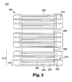
- FIG. 2 is a summary structure view of the inside of a bipolar battery 100 which is related to this embodiment.
- the bipolar battery element 160, or sub battery, and the bipolar battery 100 which is related to this embodiment is formed as follows.
- bipolar electrodes 270 are prepared in which a positive electrode layer 240 is formed on one surface of the collector 200 and a negative electrode layer 220 is formed on the other surface. Between these bipolar electrodes 270, there is formed a single battery 150 by establishing the electrolyte layer 230, e.g., a conductor or means for performing ion exchange, in order to perform ion exchange between the bipolar electrodes.
- the collector provides means for connecting the positive electrode layer and the negative electrode layer of adjacent unit batteries, e.g., single battery 150.
- a sub bipolar battery element 210 of a sub bipolar battery element by superimposing three simple unit batteries 150, and coating, using a sealing member 215, the periphery of the sub bipolar battery element 210 of the sub bipolar battery element. Furthermore there is a three layer superposition of the sub bipolar battery element 210 by means of the accumulated thickness absorption member 260, or means for absorbing thickness changes. Therefore bipolar battery element 160 of a bipolar battery element is formed.
- the collector 200 of the lowest, e.g. bottom most, layer of the bipolar battery element 160 of the bipolar battery element connects with the above-mentioned native electrode tab 120B, and the top layer of the collector 200 connects with the above-mentioned positive electrode tab 120A.
- the sub bipolar battery element 210 which is assumed to be one group of three unit batteries 150 is three groups in serial contact. Thus, between the positive tab 120A and the negative tab 120B nine times the voltage of the unit battery 150 is produced.
- the lamination does not to reduce the battery's performance from the count of the laminations of the sub bipolar battery elements 210 and from changes that would affect the thickness or characteristics of each member used to form the unit battery 150.
- sub bipolar battery elements 210 are formed as one group of three unit batteries 150, and there is alternate lamination of the sub bipolar battery element 210 groups by means of the accumulated thickness absorption member 260, and the lamination count of the unit battery 150 which forms a sub bipolar battery element 210 in the lamination count of the sub bipolar battery element 210 which forms the bipolar battery element 160 is not limited to this implementation.
- the positive electrode layer or the negative electrode layer of the bipolar electrode 270 which is facing the accumulated thickness absorption member 260 in FIG. 2 is omitted in order to reduce the parts used in the manufacturing process. It is permissible to use this as is the bipolar electrode 270 that forms the positive electrode layer or the negative electrode layer.
- each sub bipolar battery element nubile 210 is formed as one group, it is possible to remove a defective sub bipolar battery element 210 through investigations by initially charging each of the sub bipolar battery elements 210. This makes possible a dramatic improvement in manufacturing yield.
- FIG. 3 is an explanation diagram which characterizes the thickness and size of the accumulated thickness absorption member using the relationship of the size and accumulated error inside the seal member.
- the electrolyte liquid for the electrolyte layer 230 for the seal member 215 by exuding makes contact with electrodes at different voltages and is established in order to prevent the occurrence of liquid juncture by contact and is arranged to surround the periphery of the electrolyte layer 230. More specifically, sealing above and below the collector 200 which has sandwiched said electrolyte layer 230 to prevent exuding of the electrolyte.
- These seal members may use one or more of heat fused film (PE), heat hardened resins (epoxy), and optically hardened resins.
- the accumulated error A which is generated when laminating the unit batteries 150, is from the formation of the seal member 250.
- Accumulated error A is generated by defects in the thickness of the seal member numeral to learn 15 and the thickness between the layers. It may be preferable to make uniform the thickness of the seal member 215 and the thickness between the layers, uniformity is difficult during manufacturing processes. Especially, when considering the formation of the seal member 215 and the collector 200, it is necessary to have a thickness compared to the thickness between the electrodes before the process of heat fusion or heat hardening for the seal member 215, and it is desirable to perform the sealing process under pressure with said conditions. From the results, making the thickness of the seal member 215 thin is difficult, and distortions are generated due to this difficulty.
- the accumulated thickness absorption member 260 is formed so as to be small compared to the size B of the part which faces inside the battery element within the seal member 215, as shown in FIG. 3. It is desirable that the thickness be such as to be at least as large the accumulated error A. With the formation in this way, the size of the accumulated thickness absorption member 260 is larger than the size of the part which faces the battery element inside of the seal member. If the thickness of the accumulated thickness absorption member 260 is better then the accumulated error A, it is because there was no absorption of the distortion that was generated at every sub bipolar battery element 210. Moreover, in this implementation, it is possible for the accumulated error A to have a value which deducted the overall thickness between the layers from the overall thickness of the seal member which coated the sub bipolar battery element 210.
- the size of the accumulated thickness absorption member 260 is smaller than the size of the part which faces inside the battery elements within the seal member, and by forming the thickness of the accumulated thickness absorption member 260 to be thicker than the accumulated error A, because it is possible to up sure of the distortion that is generated for every sub bipolar battery element 210, there is no reduction in the battery's performance.
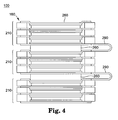
- FIG. 4 is a summary construction view of inside the bipolar battery 100 which is related to this implementation, and there is adopted material which has no conductance as the accumulated thickness absorption member 260.
- What adopting this kind of structure there is sufficient absorption of the distortions of each sub bipolar battery element nubile 210 and because there is interposed the accumulated thickness absorption member 260 which does not have conductance in between adjacent bipolar battery elements 210, 210, conductance between said so bipolar battery elements 210, 210 is not possible, and it is necessary to connect between the sub bipolar battery elements 210, 210 by a lead 290.
- FIG. 5 there has been adopted material which has conductance as the accumulated thickness absorption member 260. Because the material which has conductance which is used here as a flow of electrons in the lamination direction (thickness direction) resistance is high, and there can be no construction even using the material. However, considering the conductivity of the bipolar electrode 270 the flatness of the contact surface is high, and in addition it is desirable to select material with a low Young's modulus. For example there has been cited Cu, Al, Au, Ag, carbon and conductive polymers.
- FIG. 6 is a summary construction view of inside the bipolar battery 100 when there has been adopted fibrous carbon material as the accumulated thickness absorption member 260.
- fibrous carbon material as the accumulated thickness absorption member 260.
- FIG. 7 is a summary construction view of inside the bipolar battery 100 for this implementation. Is shown in the diagram in this implementation, there is coating using external material (outer case) for which the bipolar battery element 160 which contains three groups of sub bipolar battery elements 210 has flexibility, and the periphery is heat fused, and as was previously described, the bipolar battery element 160 is sealed such that the electrode tab 120A and the electrode tab 120B are pulled out. Moreover for the accumulated thickness absorption member 260 there is adopted a fibrous carbon sheet.
- the internal pressure of the external material 180 is established as to be lower than the atmospheric pressure, e.g., a vacuum. That is, there is additional pressure on the bipolar battery elements 160 in the lamination direction by hydrostatic pressure which used atmospheric pressure which was obtained by formation of a pressure as the internal pressure of the external material 180 to be less than the atmospheric pressure.
- hydrostatic pressure which used atmospheric pressure which was obtained by formation of a pressure as the internal pressure of the external material 180 to be less than the atmospheric pressure.
- the external material 180 By using material which has flexibility as formation material for the external material 180, said material 180 is not destroyed by pressure differences between the inside and the outside, and can easily deform.
- the material which forms the external material 180 shows electrical insulation by not being permeable to oxygen, electrons, light, or gases. With electrolytes inside and chemically stable, it is permissible to use this kind of material, such as polyethylene, polypropylene or polycarbonate as synthetic resins. If considering a reduction in possible air contact for heat fusing of the external material 180 or the electrolytes, it is desirable to select a laminated film which coats using a synthetic resin metal foil, such as aluminum.
- the above-mentioned electrolyte layered 230 be formed from solid-type electrolytes.
- solid electrolytes By using solid electrolytes as the electrolyte layer 230, it becomes possible to prevent leaks.
- liquid junctions which are characteristic problems for both electrode secondary batteries. Therefore, it becomes possible to realize bipolar batteries with high reliability.
- the following includes an explanation based on the differences between completely solid macromolecular electrolytes and macromolecular gel electrolytes.
- completely solid macromolecular electrolytes such as PEO (polyethylene oxide)
- macromolecular gel electrolytes which are included in electrolytes which are used for lithium ion batteries.
- PVDF polyethylene oxide
- PAN polyethylene oxide
- PMMA within the skeleton of the macromolecule which does not conduct lithium ions, there is correspondence with macromolecular gel electrolytes which maintain electrolytic solutions.
- the proportions of the polymer which forms the macromolecular gel electrolytes and electrolytic solutions varies widely, and assuming a polymer as 100% for the completely solid macromolecular electrolyte and assuming the liquid electrolyte is 100% electrolytic solution, the intermediate body is the macromolecular gel electrolyte.
- the completely solid type electrolyte corresponds with all of the electrolytes which conduct Li ions such as macromolecules or inorganic solids.
- the previously described positive electrode active material 2 in 40 uses a lithium transition metal complex oxidized material and is desirable to use for the negative electrode active material substance 220 carbon or lithium transition metal complex material, and from this use, it is possible to realize a bipolar battery which has excellent capacity and output characteristics.
- the above explained bipolar battery may be used to form a battery pack module 250 (FIG. 8) by connecting serially or in parallel a plurality, and is possible to form a battery pack 300 by connecting serially or in parallel a plurality old battery pack module in 250.
- Battery pack module 250 may include one or more bipolar batteries.
- FIG. 8 shows a flat surface view (FIG. A), a front view (FIG. B) and a side view (FIG. C) of the battery pack 300 and the formed battery pack module 250 mutually connects by using electrical connection means such as a bus bar, and the battery pack module 250 as multiple stages of lamination by using the connection jig 310.
- a battery pack module 250 by connecting some bipolar batteries 110, and in addition, there is formation of the battery pack 300 by laminating some stages of the battery pack module 250 which may be determined to correspond to the battery capacity and output of a vehicle which contains these batteries, e.g., an electrical car.
- an electric car 400 which contains the battery pack 300, as shown in FIG. 9, the battery pack is stored, or mounted, under the seat in the center of the electric car 400. When contained under the seat, there is the possibility of expanding space within the car and in the trunk room.
- Battery pack 300 may be stored at other locations within car 400 in other embodiments. Moreover, the location which contains the battery pack 300 is not limited to under the seat, and may be under the rear trunk room, and also in the engine space at the front of the car.
- the electrical car 400 which uses this kind of battery pack 300 as high a durability, and provide sufficient output for long-term use. Furthermore, there is provided at electrical car which is superior in running ability and a hybrid car.
- electric car 400 may be any type of motor vehicle, e.g., a truck, a bus, or a van.
- the battery pack 300 may contain only the battery pack module 250, and it may contain combinations of these battery pack 300 and battery pack modules 250.
- the vehicles which can contain this invention's battery pack or battery pack modules are preferably the above-mentioned electrical car is or hybrid cars, but the invention is not limited to these. For example the invention is appropriate for other types of electrical cars.
- the generating element 210 results from a multiple lamination alternately of bipolar electrode 270 which is formed by a positive electrode layer being formed on one surface of the conductor and a negative electrode layer being formed on the other surface and in electrolyte layer 230 which performs ion exchange between said bipolar electrodes.
- bipolar electrode 270 which is formed by a positive electrode layer being formed on one surface of the conductor and a negative electrode layer being formed on the other surface and in electrolyte layer 230 which performs ion exchange between said bipolar electrodes.
- an electrode there first is coating of electrode slurry on one surface of a stainless steel foil (SUS foil) which is a collector of thickness 20 ⁇ m and drying, with the formation of a positive electrode layer of membrane thickness 15 ⁇ m.
- the positive electrode slurry is 85 wt.% LiMNO 2 as the positive electrode active substance, 5 wt. % acetylene black as a conductive auxiliary, 10 wt. % of PVDF as binder and a mixture of NMP as slurry viscosity adjustment solvent.
- the negative electrode slurry is 90 wt. % hard carbon as negative electrode active substance, 10 wt. % PCDF as binder, and NMP as a slurry viscosity adjustment solvent.
- bipolar electrode both polarity type of electrodes.
- the completed bipolar electrode is cut into a 190 mm x 90 mm peace.
- the outer peripheral 10 mm part forms a seal layer, the electrode part is eliminating.
- a pregel is comprised of a monomer solution (polyethylene oxide and polypropylene oxide copolymer) 3 wt. % of average molecular weight between 7500 and 9000 which is a precursor of the ion conduction macromolecular matrix, 97 wt. % of PC + EC (1:1) as an electrolytic solution, and 1.5M LiBF 4 , and polymer initiator (BDK).
- a monomer solution polyethylene oxide and polypropylene oxide copolymer 3 wt. % of average molecular weight between 7500 and 9000 which is a precursor of the ion conduction macromolecular matrix, 97 wt. % of PC + EC (1:1) as an electrolytic solution, and 1.5M LiBF 4 , and polymer initiator (BDK).
- Battery elements are formed by laminating the positive electrode and a native of electrode which are facing one another with the insertion of the electrolyte; therefore, there is formation of the unit battery. By repeating this process, there is formed a battery element so that there are three layers of the unit battery which are laminated. By coding this battery element with a seal member, and first heat fusing 3 times, there is sealed the electrolyte layer as a vacuum seal of the battery element from the vacuum sealing of a final side.
- the accumulated error can be measured by subtracting the actual measured value all the thickness of the electrode part of the actual measured value of the thickness of the seal part, the accumulated error actual value of the battery element that was manufactured in this way is 56 ⁇ m.
- Embodiment 1 includes one group be the battery elements of 3 layers with a manufactured accumulated error of 56 ⁇ m as mentioned above, and an insert an accumulated error absorption member which is comprised of PET film of thickness 50 ⁇ m, and laminate 3 groups alternately as shown in FIG. 4, manufacturing 9 generating elements which have established the accumulated error absorption member.
- the part and that is insulated by establishing the accumulation error absorption member electrically conducts by connecting a lead. Afterwards there is welding of the tab which is used to draw current for the positive electrode terminal and the negative electrode terminal, manufacturing a bipolar battery which retains using a clip through insertion at the glass plate.
- Embodiment 2 is now described. Let one group be the battery elements of 3 layers with a manufactured accumulated error of 57 ⁇ m as mentioned above, and insert an accumulated absorption member which is comprised of PET film of thickness 57 ⁇ m, and laminate 3 groups alternately as shown in FIG. 4, manufacturing 9 generating elements which have established the accumulated error absorption member.
- the part and that is insulated by establishing the accumulation error absorption member electrically conducts by connecting a lead. Afterwards there is welding of the tab which is used to draw current for the positive electrode terminal and the negative electrode terminal, manufacturing a bipolar battery which retains using a clip through insertion at the glass plate.
- Embodiment 3 is now described. Let one group be the battery elements of 3 layers with a manufactured accumulated error of 56 ⁇ m as mentioned above, and insert an accumulated error absorption member which is comprised of PET film of thickness 60 ⁇ m, and laminate 3 groups alternately as shown in FIG. 4, manufacturing 9 generating elements which have established the accumulated error absorption member. In addition, the part and that is insulated by establishing the accumulation error absorption member electrically conducts by connecting a lead. Afterwards there is welding of the tab which is used to draw current for the positive electrode terminal and the negative electrode terminal, manufacturing a bipolar battery which retains using a clip through insertion at the glass plate.
- Embodiment 4 is now described. Let one group be the battery elements of 3 layers with a manufactured accumulated error of 56 ⁇ m as mentioned above, and insert an accumulated error absorption member which is comprised of metal foil of thickness 60 ⁇ m, and laminate 3 groups alternately as shown in FIG. 5, manufacturing 9 generating elements which have established the accumulated error absorption member. Afterwards there is welding of the tab which is used to draw current for the positive electrode terminal and the negative electrode terminal, manufacturing a bipolar battery which retains using a clip through insertion at the glass plate.
- Embodiment 5 is now described. Let one group be the battery elements of 3 layers with a manufactured accumulated error of 56 ⁇ m as mentioned above, and insert an accumulated error absorption member which is comprised of carbon plate of thickness 60 ⁇ m, and laminate 3 groups alternately as shown in FIG. 5, manufacturing 9 generating elements which have established the accumulated error absorption member. Afterwards there is welding of the tab which is used to draw current for the positive electrode terminal and the negative electrode terminal, manufacturing a bipolar battery which retains using a clip through insertion at the glass plate.
- Embodiment 6 is now described. Let one group be the battery elements of 3 layers with a manufactured accumulated error of 56 ⁇ m as mentioned above, and insert an accumulated error absorption member which is comprised of aluminum foil of thickness 60 ⁇ m, and laminate 3 groups alternately as shown in FIG. 5, manufacturing 9 generating elements which have established the accumulated error absorption member. Afterwards there is welding of the tab which is used to draw current for the positive electrode terminal and the negative electrode terminal, manufacturing a bipolar battery which retains using a clip through insertion at the glass plate.
- Embodiment 7 is now described. Let one group be the battery elements of 3 layers with a manufactured accumulated error of 56 ⁇ m as mentioned above, and insert an accumulated error absorption member which is comprised of fibrous carbon sheet of thickness 60 ⁇ m, and laminate 3 groups alternately as shown in FIG. 6, manufacturing 9 generating elements which have established the accumulated error absorption member. Afterwards there is welding of the tab which is used to draw current for the positive electrode terminal and the negative electrode terminal, manufacturing a bipolar battery which retains using a clip through insertion at the glass plate.
- Embodiment 8 is now described. Let one group be the battery elements of 3 layers with a manufactured accumulated error of 56 ⁇ m as mentioned above, and insert an accumulated error absorption member which is comprised of fibrous carbon sheet of thickness 60 ⁇ m, and laminate 3 groups alternately as shown in FIG. 6, manufacturing 9 generating elements which have established the accumulated error absorption member. Afterwards there is welding of the tab which is used to draw current for the positive electrode terminal and the negative electrode terminal, manufacturing a bipolar battery by vacuum sealing an aluminum laminate.
- Each of the bipolar batteries of Embodiments 1 to 8 was manufactured for comparison as explained above, and there was an evaluation of these bipolar batteries under the following conditions.
- Embodiments 1 through 8 are shown when assuming 100% discharge capacity for the comparative example.
- TABLE 1 Discharge capacity (comparative example 100%) Embodiment 1 123% Embodiment 2 150% Embodiment 3 151% Embodiment 4 150% Embodiment 5 158% Embodiment 6 157% Embodiment 7 160% Embodiment 8 159%
- Embodiments 1 through 8 are shown assuming a 100% resistance value for the comparative example. TABLE 2 Resistance values (comparative example 100%) Embodiment 1 85% Embodiment 2 82% Embodiment 3 83% Embodiment 4 63% Embodiment 5 62% Embodiment 6 60% Embodiment 7 50% Embodiment 8 42%
- the discharge capacity of the Embodiments 1 to 8 have a greater discharge capacity than the comparative example. This is because the battery of the comparative example which had accumulated errors did not maintain accurately separation between layers, it is thought that this resulted in a difficult discharge. Consequently, it is determined that battery performance is better by establishing an accumulated thickness absorption member between the battery elements.
- Embodiment 1 has a somewhat reduced capacity. Consequently from these results, is determined that it is appropriate that the thickness of the accumulated thickness absorption member be at least greater than the accumulated error.
- Embodiment 1 to 3 is greater than Embodiments 4 to 6, which are greater than Embodiment 7, which is greater than Embodiment 8. From these results it is desirable to select material which has conductivity for the accumulated thickness absorption member, and to have a fibrous carbon material which has low resistance.
- Embodiments 1 through 3 there was high resistance for those materials which connected with the electrodes with leads. This was because the connection surface of the lead and the electrode was limited.
- Embodiments 4 through 8 although the resistance of the accumulation thickness absorption member was large compared to the lead with surface connections, the overall resistance value compared to the lead became small because the separation was narrow. Furthermore, vacuum sealing by an aluminum laminate to raise the adhesion of every member by a pressure difference from the atmosphere outside and a vacuum for Embodiment 8, Embodiment 8 showed the lowest resistance value.
Landscapes
- Engineering & Computer Science (AREA)
- Chemical & Material Sciences (AREA)
- Chemical Kinetics & Catalysis (AREA)
- Electrochemistry (AREA)
- General Chemical & Material Sciences (AREA)
- Manufacturing & Machinery (AREA)
- Sustainable Energy (AREA)
- Sustainable Development (AREA)
- Life Sciences & Earth Sciences (AREA)
- Power Engineering (AREA)
- Transportation (AREA)
- Mechanical Engineering (AREA)
- Secondary Cells (AREA)
- Connection Of Batteries Or Terminals (AREA)
- Battery Electrode And Active Subsutance (AREA)
- Arrangement Or Mounting Of Propulsion Units For Vehicles (AREA)
- Sealing Battery Cases Or Jackets (AREA)
- Battery Mounting, Suspending (AREA)
Abstract
Description
- The invention is concerned with improvements in or relating to batteries and particularly, but not exclusively, to bipolar batteries, including those used in vehicles such as automobiles.
- A bipolar battery is a battery which forms a positive electrode layer on one surface of a collector and a negative electrode layer on another surface. These surfaces are arranged in an alternating fashion with an electrolyte layer that performs ion replacement between each bipolar electrodes. If the connections between the electrodes at the ends of this kind of bipolar battery come in contact, there is a short circuit, and in addition, if the electrolyte layers come into contact, there a liquid junction would be formed.
- To counteract these problems, some bipolar batteries utilize a coating, using an insulating material, of the periphery of a unit battery formed by sandwiching the separator that has been immersed in an electrolyte between the positive and negative electrodes. In addition, the periphery of the unit battery is formed by laminating using a conducting foil to prevent a liquid junction or short circuit between each electrode.
- It is an aim of the invention to improve upon conventional technology. Other aims and advantages of the invention will become apparent from the following description, claims and abstract.
- Aspects of the invention therefore provide a battery, a method and a vehicle as claimed in the appended claims.
- According to another aspect of the invention there is provided a bipolar battery comprising a plurality of sub battery elements including a plurality of collectors that are arranged in an alternating fashion with an conductor that performs ion exchange between a positive electrode layer formed on the one surface of the collector and the negative electrode layer formed on the other surface of the collector and an accumulated thickness absorption member that is arranged between the sub battery elements.
- In an embodiment, the sub battery element has the collector which faces to the accumulated thickness absorption member, and the collector has only one of the positive electrode layer or the negative electrode layer on the opposite surface of the accumulated thickness absorption member.
- The sub battery may comprise a seal member that prevents the conductor from leaking between the collectors.
- In an embodiment, the accumulation thickness absorption member absorbs a difference in thickness of the seal layer, the positive electrode layer, and the negative electrode layer.
- In an embodiment, the accumulation thickness absorption member comprising a small service area inside of the seal layer and above the conductor in a lamination direction.
- In an embodiment, the accumulation thickness absorption member is formed of a conductive material.
- In an embodiment, the accumulation thickness absorption member is formed of a fibrous carbon material.
- The battery may comprise an external member surrounding the multiple sub battery elements, wherein the internal pressure within the external member is less than an atmospheric pressure.
- In an embodiment, the external material is a laminate film comprising metal foil and a synthetic resin membrane.
- In an embodiment, the conductor is a solid type electrolyte substance.
- In an embodiment, the positive electrode layer comprises a lithium transition metal complex oxide substance, and wherein the negative electrode layer comprises at least one of a carbon and a lithium transition metal complex oxide substance.
- The battery may comprise a motor vehicle, wherein the battery is a power source for the motor vehicle.
- According to another aspect of the invention there is provided a bipolar battery comprising a plurality of sub battery elements including a plurality of collectors that comprise a positive electrode layer on one surface and a negative electrode layer on another surface and a conductor disposed between the collectors, wherein the conductor performs ion exchange between the positive electrode layer formed on the one collector and the negative electrode layer formed on the other collector and means for absorbing thickness changes that is arranged between the collector of the one sub battery element and the collector of the other sub battery element.
- According to a further aspect of the invention there is provided a method for manufacturing a bipolar battery comprising forming two or more sub battery elements by stacking two or more unit batteries for each of the battery elements, wherein each unit battery is constructed by forming a positive electrode layer on one surface of a collector and a negative electrode layer on another surface of the collector, forming a conductor by laminating an electrode layer that performs ion exchange between a positive electrode layer and a negative electrode layer, wherein the positive electrode layer is disposed on an opposite side of the conductor to the negative electrode layer, forming a seal layer on a periphery of the electrolyte layer to prevent electrolyte leakage and positioning an accumulation thickness absorption member between the collector of a first sub battery element and the collector of a second sub battery element.
- The method may comprise administering pressure to the battery element after positioning the accumulation thickness absorption member.
- The method may comprise stacking three battery elements, wherein each battery element is separated by one of two accumulation thickness absorption members and comprises three unit batteries.
- The method may comprise surrounding multiple battery elements with an external member and creating a vacuum within the external member.
- In general, embodiments of the invention are directed to a bipolar battery that reduces thickness distortions to prevent degradation in battery performance. With an increase in the number of laminations of the bipolar battery, as known in conventional batteries, there may be distortions generated from defects in the thicknesses of the electrode material that may reduce the battery's performance. Consequently, problems occur which reduce the manufacturing yield from the addition of lamination layers.
- An embodiment of the invention may provide a solution to conventional technical problems with bipolar batteries, by preventing the occurrence of distortions from defects of the thicknesses of the electrode members and the reduction in the battery's performance due to this distortion. Provided herein is a description of a bipolar battery which may improve the manufacturing yield, along with a battery pack and a vehicle which contains these batteries.
- In one embodiment, a bipolar battery includes a plurality of sub battery elements. Each sub battery element includes a plurality of collectors that are arranged in an alternating fashion with an conductor that performs ion exchange between a positive electrode layer formed on the one surface of the collector and the negative electrode layer formed on the other surface of the collector and an accumulated thickness absorption member that is arranged between the sub battery elements.
- In another embodiment, a bipolar battery includes a plurality of sub battery elements, where each sub battery element includes a plurality of collectors that comprise a positive electrode layer on one surface and a negative electrode layer on another surface and a conductor disposed between the collectors, wherein the conductor performs ion exchange between the positive electrode layer formed on the one collector and the negative electrode layer formed on the other collector. The bipolar battery also includes means for absorbing thickness changes that is arranged between the collector of the one sub battery element and the collector of the other sub battery element.
- In an alternative embodiment, a method for manufacturing a bipolar battery includes forming two or more sub battery elements by stacking two or more unit batteries for each of the battery elements, wherein each unit battery is constructed by forming a positive electrode layer on one surface of a collector and a negative electrode layer on another surface of the collector and forming a conductor by laminating an electrode layer that performs ion exchange between a positive electrode layer and a negative electrode layer, wherein the positive electrode layer is disposed on an opposite side of the conductor to the negative electrode layer. Each unit battery may also be formed by forming a seal layer on a periphery of the electrolyte layer to prevent electrolyte leakage. The bipolar battery is also manufactured by positioning an accumulation thickness absorption member between the collector of a first sub battery element and the collector of a second sub battery element.
- Within the scope of this application it is envisaged that the various aspects, embodiments and alternatives set out in the preceding paragraphs, in the claims and in the following description may be taken individually or in any combination thereof.
- The present invention will now be described, by way of example only, with reference to the accompanying drawings in which:
- FIG. 1 is an external view of the bipolar battery which is related to one embodiment;
- FIG. 2 is a summary structure view of inside a bipolar battery which is related to an embodiment;
- FIG. 3 is a diagram using the relationship of the size and accumulated error difference in size of the external material categorizing the size and thickness of the accumulated thickness absorption member;
- FIG. 4 is a summary structure view of inside the bipolar battery with material which does not have conductivity of the accumulated thickness absorption member for Embodiments 1 to 3;
- FIG. 5 is a summary structure view of inside the bipolar battery with material which does have conductivity of the accumulated thickness absorption member for Embodiments 4 to 6;
- FIG. 6 is a summary structure view of inside the bipolar battery when fibrous carbon sheet has been adopted as the accumulated fitness absorption member for Embodiments 7 and 8;
- FIG. 7 is a summary structure view of inside the bipolar battery which is related to an embodiment;
- FIG. 8 is a summary structure view of the battery pack; and
- FIG. 9 is an illustration which shows the conditions under which the battery pack is contained in a vehicle.
- Provided herein is a detailed explanation of the implementation of a bipolar battery, a battery pack, and a vehicle which contains these batteries which is related to this invention and based on the drawings. Moreover, the drawings which are utilized to illustrate the below implementation are drawn by exaggerating the thickness or form of each layer, for easy understanding of the contents of the invention, and are not representative of adjustments to have been made for the thickness or form of every layer of an actual bipolar battery.
- FIG. 1 is an external view of a bipolar battery which is related to this implementation. The
bipolar battery 100 as a longitudinal flat shape as shown in the FIG. 1, and from both sides thepositive electrode tab 120A and thenegative electrode tab 120B are taken out in order to draw power. Thebipolar battery element 160 is wrapped according to an external member of thebipolar battery 100, and its periphery is then used, and thebipolar battery element 160 is sealed under conditions whereby thepositive electrode tab 120A and thenegative electrode tab 120B are pulled out. - FIG. 2 is a summary structure view of the inside of a
bipolar battery 100 which is related to this embodiment. Thebipolar battery element 160, or sub battery, and thebipolar battery 100 which is related to this embodiment is formed as follows. First,bipolar electrodes 270 are prepared in which apositive electrode layer 240 is formed on one surface of thecollector 200 and anegative electrode layer 220 is formed on the other surface. Between thesebipolar electrodes 270, there is formed asingle battery 150 by establishing theelectrolyte layer 230, e.g., a conductor or means for performing ion exchange, in order to perform ion exchange between the bipolar electrodes. The collector provides means for connecting the positive electrode layer and the negative electrode layer of adjacent unit batteries, e.g.,single battery 150. There is formed a subbipolar battery element 210 of a sub bipolar battery element by superimposing threesimple unit batteries 150, and coating, using asealing member 215, the periphery of the subbipolar battery element 210 of the sub bipolar battery element. Furthermore there is a three layer superposition of the subbipolar battery element 210 by means of the accumulatedthickness absorption member 260, or means for absorbing thickness changes. Thereforebipolar battery element 160 of a bipolar battery element is formed. - The
collector 200 of the lowest, e.g. bottom most, layer of thebipolar battery element 160 of the bipolar battery element connects with the above-mentionednative electrode tab 120B, and the top layer of thecollector 200 connects with the above-mentionedpositive electrode tab 120A. Because for thebipolar battery element 160 which is shown in FIG. 2, the subbipolar battery element 210 which is assumed to be one group of threeunit batteries 150 is three groups in serial contact. Thus, between thepositive tab 120A and thenegative tab 120B nine times the voltage of theunit battery 150 is produced. - If the above-mentioned accumulated
thickness absorption member 260 has absorbable thickness or form such that there are distortions between the subbipolar battery elements bipolar battery elements 210 and from changes that would affect the thickness or characteristics of each member used to form theunit battery 150. Moreover, in this implementation, subbipolar battery elements 210 are formed as one group of threeunit batteries 150, and there is alternate lamination of the subbipolar battery element 210 groups by means of the accumulatedthickness absorption member 260, and the lamination count of theunit battery 150 which forms a subbipolar battery element 210 in the lamination count of the subbipolar battery element 210 which forms thebipolar battery element 160 is not limited to this implementation. In addition, the positive electrode layer or the negative electrode layer of thebipolar electrode 270 which is facing the accumulatedthickness absorption member 260 in FIG. 2 is omitted in order to reduce the parts used in the manufacturing process. It is permissible to use this as is thebipolar electrode 270 that forms the positive electrode layer or the negative electrode layer. - That is, by establishing an accumulated
thickness absorption member 260 between the subbipolar battery elements bipolar battery elements 210, the accumulatedthickness absorption member 260 prevents a reduction in battery performance by absorbing the distortion of each subbipolar battery element 210. In addition, because each sub bipolar battery element nubile 210 is formed as one group, it is possible to remove a defective subbipolar battery element 210 through investigations by initially charging each of the subbipolar battery elements 210. This makes possible a dramatic improvement in manufacturing yield. - FIG. 3 is an explanation diagram which characterizes the thickness and size of the accumulated thickness absorption member using the relationship of the size and accumulated error inside the seal member. A shell and in the diagram, the above-mentioned so bipolar battery element nubile to 10 is coated by a
seal member 215. - The electrolyte liquid for the
electrolyte layer 230 for theseal member 215 by exuding makes contact with electrodes at different voltages and is established in order to prevent the occurrence of liquid juncture by contact and is arranged to surround the periphery of theelectrolyte layer 230. More specifically, sealing above and below thecollector 200 which has sandwiched saidelectrolyte layer 230 to prevent exuding of the electrolyte. These seal members may use one or more of heat fused film (PE), heat hardened resins (epoxy), and optically hardened resins. - The accumulated error A, which is generated when laminating the
unit batteries 150, is from the formation of theseal member 250. Accumulated error A is generated by defects in the thickness of the seal member numeral to learn 15 and the thickness between the layers. It may be preferable to make uniform the thickness of theseal member 215 and the thickness between the layers, uniformity is difficult during manufacturing processes. Especially, when considering the formation of theseal member 215 and thecollector 200, it is necessary to have a thickness compared to the thickness between the electrodes before the process of heat fusion or heat hardening for theseal member 215, and it is desirable to perform the sealing process under pressure with said conditions. From the results, making the thickness of theseal member 215 thin is difficult, and distortions are generated due to this difficulty. - The accumulated
thickness absorption member 260 is formed so as to be small compared to the size B of the part which faces inside the battery element within theseal member 215, as shown in FIG. 3. It is desirable that the thickness be such as to be at least as large the accumulated error A. With the formation in this way, the size of the accumulatedthickness absorption member 260 is larger than the size of the part which faces the battery element inside of the seal member. If the thickness of the accumulatedthickness absorption member 260 is better then the accumulated error A, it is because there was no absorption of the distortion that was generated at every subbipolar battery element 210. Moreover, in this implementation, it is possible for the accumulated error A to have a value which deducted the overall thickness between the layers from the overall thickness of the seal member which coated the subbipolar battery element 210. - In this way, by forming the size of the accumulated
thickness absorption member 260 to be smaller than the size of the part which faces inside the battery elements within the seal member, and by forming the thickness of the accumulatedthickness absorption member 260 to be thicker than the accumulated error A, because it is possible to up sure of the distortion that is generated for every subbipolar battery element 210, there is no reduction in the battery's performance. - FIG. 4 is a summary construction view of inside the
bipolar battery 100 which is related to this implementation, and there is adopted material which has no conductance as the accumulatedthickness absorption member 260. What adopting this kind of structure, there is sufficient absorption of the distortions of each sub bipolar battery element nubile 210 and because there is interposed the accumulatedthickness absorption member 260 which does not have conductance in between adjacentbipolar battery elements bipolar battery elements bipolar battery elements lead 290. - With respect to this, in FIG. 5, there has been adopted material which has conductance as the accumulated
thickness absorption member 260. Because the material which has conductance which is used here as a flow of electrons in the lamination direction (thickness direction) resistance is high, and there can be no construction even using the material. However, considering the conductivity of thebipolar electrode 270 the flatness of the contact surface is high, and in addition it is desirable to select material with a low Young's modulus. For example there has been cited Cu, Al, Au, Ag, carbon and conductive polymers. - By forming in this way the accumulation thickness absorption member 2 out of 60 using the curios which are conductive, while distorting the distortion for each sub why
polar battery element 210, conduction becomes possible between adjacent subbipolar battery elements - FIG. 6 is a summary construction view of inside the
bipolar battery 100 when there has been adopted fibrous carbon material as the accumulatedthickness absorption member 260. When forming the accumulatedthickness absorption material 260, using a sheet-shaped fibrous carbon material, it is possible to establish a low Young's modulus from the characteristics of the fibrous material. In addition, because there is carbon material even in the fibrous material, it becomes possible to conduct between adjacent subbipolar battery elements - FIG. 7 is a summary construction view of inside the
bipolar battery 100 for this implementation. Is shown in the diagram in this implementation, there is coating using external material (outer case) for which thebipolar battery element 160 which contains three groups of subbipolar battery elements 210 has flexibility, and the periphery is heat fused, and as was previously described, thebipolar battery element 160 is sealed such that theelectrode tab 120A and theelectrode tab 120B are pulled out. Moreover for the accumulatedthickness absorption member 260 there is adopted a fibrous carbon sheet. - The internal pressure of the
external material 180 is established as to be lower than the atmospheric pressure, e.g., a vacuum. That is, there is additional pressure on thebipolar battery elements 160 in the lamination direction by hydrostatic pressure which used atmospheric pressure which was obtained by formation of a pressure as the internal pressure of theexternal material 180 to be less than the atmospheric pressure. With the addition of a magnetic force from a magnet, and by imparting hydrostatic pressure which uses atmospheric pressure, and by making it use of the current of theunit batteries 150 which are serially connected within thebipolar battery element 160 of the entire surface of the electrode by strong electrical terminals, it is possible to counter variations in the current density distribution. - By using material which has flexibility as formation material for the
external material 180, saidmaterial 180 is not destroyed by pressure differences between the inside and the outside, and can easily deform. The material which forms theexternal material 180 shows electrical insulation by not being permeable to oxygen, electrons, light, or gases. With electrolytes inside and chemically stable, it is permissible to use this kind of material, such as polyethylene, polypropylene or polycarbonate as synthetic resins. If considering a reduction in possible air contact for heat fusing of theexternal material 180 or the electrolytes, it is desirable to select a laminated film which coats using a synthetic resin metal foil, such as aluminum. - Captain is lamé film which is used which is comprised of metal foil and synthetic resin membranes as the
external material 180, it becomes possible to have hydrostatic pressure because of the easy deformation of the resin film. Furthermore, because of the existence of the metal foil there is a reduction and gas permeability, thus making possible on a long-term basis the maintenance of pressure difference between the inside and the outside of theexternal material 180. - In addition, it is desirable that the above-mentioned electrolyte layered 230 be formed from solid-type electrolytes. By using solid electrolytes as the
electrolyte layer 230, it becomes possible to prevent leaks. In addition, it is possible to prevent liquid junctions which are characteristic problems for both electrode secondary batteries. Therefore, it becomes possible to realize bipolar batteries with high reliability. - The following includes an explanation based on the differences between completely solid macromolecular electrolytes and macromolecular gel electrolytes. There are the completely solid macromolecular electrolytes such as PEO (polyethylene oxide) and the macromolecular gel electrolytes which are included in electrolytes which are used for lithium ion batteries. In addition, as with PVDF, PAN, and PMMA, within the skeleton of the macromolecule which does not conduct lithium ions, there is correspondence with macromolecular gel electrolytes which maintain electrolytic solutions. The proportions of the polymer which forms the macromolecular gel electrolytes and electrolytic solutions varies widely, and assuming a polymer as 100% for the completely solid macromolecular electrolyte and assuming the liquid electrolyte is 100% electrolytic solution, the intermediate body is the macromolecular gel electrolyte. In addition, the completely solid type electrolyte corresponds with all of the electrolytes which conduct Li ions such as macromolecules or inorganic solids. In this invention, when one speaks of a solid-type electrolyte, it is assumed to include all macromolecular gel electrolyte, completely solid macromolecular electrolyte and inorganic solid electrolytes.
- Furthermore the previously described positive electrode active material 2 in 40 uses a lithium transition metal complex oxidized material and is desirable to use for the negative electrode
active material substance 220 carbon or lithium transition metal complex material, and from this use, it is possible to realize a bipolar battery which has excellent capacity and output characteristics. - The above explained bipolar battery may be used to form a battery pack module 250 (FIG. 8) by connecting serially or in parallel a plurality, and is possible to form a
battery pack 300 by connecting serially or in parallel a plurality old battery pack module in 250.Battery pack module 250 may include one or more bipolar batteries. FIG. 8 shows a flat surface view (FIG. A), a front view (FIG. B) and a side view (FIG. C) of thebattery pack 300 and the formedbattery pack module 250 mutually connects by using electrical connection means such as a bus bar, and thebattery pack module 250 as multiple stages of lamination by using theconnection jig 310. There is formed abattery pack module 250 by connecting some bipolar batteries 110, and in addition, there is formation of thebattery pack 300 by laminating some stages of thebattery pack module 250 which may be determined to correspond to the battery capacity and output of a vehicle which contains these batteries, e.g., an electrical car. - In this way, it is possible to obtain a
battery pack 300 which is formed by connecting in parallel or serially a plurality of thebattery pack modules 250 so as to be able to obtain high-capacity and high output, and because reliability is high for thebattery pack modules 250 separately, there is a possibility of maintaining long-term reliability for thebattery pack 300. In addition, even if one of thebattery pack modules 250 breaks down, it is possible to repair by exchanging only the nonfunctional part. - In an
electric car 400 which contains thebattery pack 300, as shown in FIG. 9, the battery pack is stored, or mounted, under the seat in the center of theelectric car 400. When contained under the seat, there is the possibility of expanding space within the car and in the trunk room.Battery pack 300 may be stored at other locations withincar 400 in other embodiments. Moreover, the location which contains thebattery pack 300 is not limited to under the seat, and may be under the rear trunk room, and also in the engine space at the front of the car. Theelectrical car 400 which uses this kind ofbattery pack 300 as high a durability, and provide sufficient output for long-term use. Furthermore, there is provided at electrical car which is superior in running ability and a hybrid car. In other embodiments,electric car 400 may be any type of motor vehicle, e.g., a truck, a bus, or a van. - Moreover, not only is the
battery pack 300 useful in applications, it may contain only thebattery pack module 250, and it may contain combinations of thesebattery pack 300 andbattery pack modules 250. In addition, the vehicles which can contain this invention's battery pack or battery pack modules are preferably the above-mentioned electrical car is or hybrid cars, but the invention is not limited to these. For example the invention is appropriate for other types of electrical cars. - Below, there is an explanation of embodiments of the bipolar battery which are related to this invention, but this invention is not limited to these embodiments.
- Initially there is an explanation for the manufacture of the above-mentioned
generating element 210 which is common to Embodiments 1 through 8. As explained above, the generatingelement 210 results from a multiple lamination alternately ofbipolar electrode 270 which is formed by a positive electrode layer being formed on one surface of the conductor and a negative electrode layer being formed on the other surface and inelectrolyte layer 230 which performs ion exchange between said bipolar electrodes. There is lamination of a plurality ofunit batteries 150. - To form an electrode, there first is coating of electrode slurry on one surface of a stainless steel foil (SUS foil) which is a collector of thickness 20 µm and drying, with the formation of a positive electrode layer of membrane thickness 15 µm. The positive electrode slurry is 85 wt.% LiMNO2 as the positive electrode active substance, 5 wt. % acetylene black as a conductive auxiliary, 10 wt. % of PVDF as binder and a mixture of NMP as slurry viscosity adjustment solvent.
- Next, there is coating and drying of the negative electrode slurry on the opposite surface of the conductor (SUS 40) which coded the positive electrode layer, and formation of a negative electrode layer of membrane thickness 15 µm. The negative electrode slurry is 90 wt. % hard carbon as negative electrode active substance, 10 wt. % PCDF as binder, and NMP as a slurry viscosity adjustment solvent.
- By respectively forming the positive electrode layer and the negative electrode layer on both surfaces of the collector (SUS foil), there is formed a bipolar electrode (both polarity type of electrodes). The completed bipolar electrode is cut into a 190 mm x 90 mm peace. In addition, because the outer peripheral 10 mm part forms a seal layer, the electrode part is eliminating. Moreover, there is coating of a positive electrode layer or a negative electrode layer on only one surface for the positive electrode terminal polarity and the negative electrode polarity.
- By immersing the separator of polyethylene manufacture (thickness 12 µm), there is obtained a precursor by irradiating for 15 minutes ultraviolet rays inserting into the quartz glass substrate. A pregel is comprised of a monomer solution (polyethylene oxide and polypropylene oxide copolymer) 3 wt. % of average molecular weight between 7500 and 9000 which is a precursor of the ion conduction macromolecular matrix, 97 wt. % of PC + EC (1:1) as an electrolytic solution, and 1.5M LiBF4, and polymer initiator (BDK).
- Battery elements are formed by laminating the positive electrode and a native of electrode which are facing one another with the insertion of the electrolyte; therefore, there is formation of the unit battery. By repeating this process, there is formed a battery element so that there are three layers of the unit battery which are laminated. By coding this battery element with a seal member, and first heat fusing 3 times, there is sealed the electrolyte layer as a vacuum seal of the battery element from the vacuum sealing of a final side.
- The battery element has a seal member thickness for a single layer of 62 µm, and the thickness between layers which is the sum total of the electrode and the separator is 44 µm, and the accumulated error for the unit layer is 62 µm ― 44 µm = 18 µ. Because there have been superimposed three layers of the battery element the accumulated error becomes 54 µm.
- The accumulated error can be measured by subtracting the actual measured value all the thickness of the electrode part of the actual measured value of the thickness of the seal part, the accumulated error actual value of the battery element that was manufactured in this way is 56 µm.
- Below, there is an explanation for Embodiments 1 to 8 and a comparative example. Embodiment 1 includes one group be the battery elements of 3 layers with a manufactured accumulated error of 56 µm as mentioned above, and an insert an accumulated error absorption member which is comprised of PET film of thickness 50 µm, and laminate 3 groups alternately as shown in FIG. 4, manufacturing 9 generating elements which have established the accumulated error absorption member. In addition, the part and that is insulated by establishing the accumulation error absorption member electrically conducts by connecting a lead. Afterwards there is welding of the tab which is used to draw current for the positive electrode terminal and the negative electrode terminal, manufacturing a bipolar battery which retains using a clip through insertion at the glass plate.
- Embodiment 2 is now described. Let one group be the battery elements of 3 layers with a manufactured accumulated error of 57 µm as mentioned above, and insert an accumulated absorption member which is comprised of PET film of thickness 57 µm, and laminate 3 groups alternately as shown in FIG. 4, manufacturing 9 generating elements which have established the accumulated error absorption member. In addition, the part and that is insulated by establishing the accumulation error absorption member electrically conducts by connecting a lead. Afterwards there is welding of the tab which is used to draw current for the positive electrode terminal and the negative electrode terminal, manufacturing a bipolar battery which retains using a clip through insertion at the glass plate.
- Embodiment 3 is now described. Let one group be the battery elements of 3 layers with a manufactured accumulated error of 56 µm as mentioned above, and insert an accumulated error absorption member which is comprised of PET film of thickness 60 µm, and laminate 3 groups alternately as shown in FIG. 4, manufacturing 9 generating elements which have established the accumulated error absorption member. In addition, the part and that is insulated by establishing the accumulation error absorption member electrically conducts by connecting a lead. Afterwards there is welding of the tab which is used to draw current for the positive electrode terminal and the negative electrode terminal, manufacturing a bipolar battery which retains using a clip through insertion at the glass plate.
- Embodiment 4 is now described. Let one group be the battery elements of 3 layers with a manufactured accumulated error of 56 µm as mentioned above, and insert an accumulated error absorption member which is comprised of metal foil of thickness 60 µm, and laminate 3 groups alternately as shown in FIG. 5, manufacturing 9 generating elements which have established the accumulated error absorption member. Afterwards there is welding of the tab which is used to draw current for the positive electrode terminal and the negative electrode terminal, manufacturing a bipolar battery which retains using a clip through insertion at the glass plate.
- Embodiment 5 is now described. Let one group be the battery elements of 3 layers with a manufactured accumulated error of 56 µm as mentioned above, and insert an accumulated error absorption member which is comprised of carbon plate of thickness 60 µm, and laminate 3 groups alternately as shown in FIG. 5, manufacturing 9 generating elements which have established the accumulated error absorption member. Afterwards there is welding of the tab which is used to draw current for the positive electrode terminal and the negative electrode terminal, manufacturing a bipolar battery which retains using a clip through insertion at the glass plate.
- Embodiment 6 is now described. Let one group be the battery elements of 3 layers with a manufactured accumulated error of 56 µm as mentioned above, and insert an accumulated error absorption member which is comprised of aluminum foil of thickness 60 µm, and laminate 3 groups alternately as shown in FIG. 5, manufacturing 9 generating elements which have established the accumulated error absorption member. Afterwards there is welding of the tab which is used to draw current for the positive electrode terminal and the negative electrode terminal, manufacturing a bipolar battery which retains using a clip through insertion at the glass plate.
- Embodiment 7 is now described. Let one group be the battery elements of 3 layers with a manufactured accumulated error of 56 µm as mentioned above, and insert an accumulated error absorption member which is comprised of fibrous carbon sheet of thickness 60 µm, and laminate 3 groups alternately as shown in FIG. 6, manufacturing 9 generating elements which have established the accumulated error absorption member. Afterwards there is welding of the tab which is used to draw current for the positive electrode terminal and the negative electrode terminal, manufacturing a bipolar battery which retains using a clip through insertion at the glass plate.
- Embodiment 8 is now described. Let one group be the battery elements of 3 layers with a manufactured accumulated error of 56 µm as mentioned above, and insert an accumulated error absorption member which is comprised of fibrous carbon sheet of thickness 60 µm, and laminate 3 groups alternately as shown in FIG. 6, manufacturing 9 generating elements which have established the accumulated error absorption member. Afterwards there is welding of the tab which is used to draw current for the positive electrode terminal and the negative electrode terminal, manufacturing a bipolar battery by vacuum sealing an aluminum laminate.
- As a comparable example, let one group be the battery elements of 3 layers with a manufactured accumulated error of 56 µm as mentioned above and laminate without inserting an accumulation error absorption member, to produce 9 generating elements. Afterwards there is welding of the tab which is used to draw current for the positive electrode terminal and the negative electrode terminal, manufacturing a bipolar battery which retains using a clip through insertion at the glass plate.
- Each of the bipolar batteries of Embodiments 1 to 8 was manufactured for comparison as explained above, and there was an evaluation of these bipolar batteries under the following conditions.
- There was charging to a fixed current fixed voltage (CCCV) for 15 minutes up to 50.4V using a current of 10 mA for these batteries. Afterwards there was a five second discharge in at a current of 10mA, with measurements taken at this time of the electrical capacitance, and measurements of the discharge capacity from the initial electrical capacitance. In Table 1 below, the discharge capacity of Embodiments 1 through 8 are shown when assuming 100% discharge capacity for the comparative example.
TABLE 1 Discharge capacity (comparative example = 100%) Embodiment 1 123% Embodiment 2 150% Embodiment 3 151% Embodiment 4 150% Embodiment 5 158% Embodiment 6 157% Embodiment 7 160% Embodiment 8 159% - Next, there was charging to a fixed current fixed voltage (CCCV) for 15 minutes up to 50.4V using a current of 10 mA for these batteries. Afterwards there was a five second discharge in at a current of 10mA, with measurements taken at this time of the voltage, and measurements of the resistance values from the initial decreasing voltage. In Table 2 below, the resistance values of Embodiments 1 through 8 are shown assuming a 100% resistance value for the comparative example.
TABLE 2 Resistance values (comparative example 100%) Embodiment 1 85% Embodiment 2 82% Embodiment 3 83% Embodiment 4 63% Embodiment 5 62% Embodiment 6 60% Embodiment 7 50% Embodiment 8 42% - From the results of Table 1, the discharge capacity of the Embodiments 1 to 8 have a greater discharge capacity than the comparative example. This is because the battery of the comparative example which had accumulated errors did not maintain accurately separation between layers, it is thought that this resulted in a difficult discharge. Consequently, it is determined that battery performance is better by establishing an accumulated thickness absorption member between the battery elements.
- In addition, comparing Embodiment 1 and Embodiments 2 to 8, Embodiment 1 has a somewhat reduced capacity. Consequently from these results, is determined that it is appropriate that the thickness of the accumulated thickness absorption member be at least greater than the accumulated error.
- From the results of Table 2, it is determined that for the resistance values have the relationship of Embodiment 1 to 3 is greater than Embodiments 4 to 6, which are greater than Embodiment 7, which is greater than Embodiment 8. From these results it is desirable to select material which has conductivity for the accumulated thickness absorption member, and to have a fibrous carbon material which has low resistance. In Embodiments 1 through 3, there was high resistance for those materials which connected with the electrodes with leads. This was because the connection surface of the lead and the electrode was limited. In contrast, for Embodiments 4 through 8, although the resistance of the accumulation thickness absorption member was large compared to the lead with surface connections, the overall resistance value compared to the lead became small because the separation was narrow. Furthermore, vacuum sealing by an aluminum laminate to raise the adhesion of every member by a pressure difference from the atmosphere outside and a vacuum for Embodiment 8, Embodiment 8 showed the lowest resistance value.
- This application claims priority to
Japanese Patent Application No. 2005- 203723, filed July 12, 2005 - Various embodiments of the invention have been described. These and other embodiments are within the scope of the following claims.
Claims (14)
- A bipolar battery comprising:a plurality of sub battery elements including a plurality of collectors having a positive electrode layer on one surface and a negative electrode layer on another surface and conductor means disposed between the collectors, the conductor means being arranged to permit ion exchange between the positive electrode layer formed on the one collector and the negative electrode layer formed on the other collector; andaccumulated thickness absorption means disposed between the collector of the one sub battery element and the collector of the other sub battery element for absorbing thickness changes.
- A battery as claimed in claim 1 wherein at least one sub battery element has a collector which faces the accumulated thickness absorption means and wherein the collector has only one of the positive electrode layer or the negative electrode layer on the opposite surface of the accumulated thickness absorption means.
- A battery as claimed in claim 1 or claim 2 wherein at least one sub battery comprises a seal member that prevents the conductor means from leaking between the collectors.
- A battery as claimed in claim 3 wherein the accumulation thickness absorption means is arranged to absorb a difference in thickness of the seal member, the positive electrode layer, and the negative electrode layer.
- A battery as claimed in claim 3 or claim 4 werein the accumulation thickness absorption means compries a small service area inside of the seal layer and above the conductor means in a lamination direction.
- A battery as claimed in any preceding claim wherein the accumulation thickness absorption means is formed of a conductive material, such as a fibrous carbon material.
- A battery as claimed in any preceding claim comprising an external member surrounding the plurality of sub battery elements, wherein an internal pressure within the external member is less than an atmospheric pressure.
- A battery as claimed in claim 7 wherein the external member is a laminate film comprising metal foil and a synthetic resin membrane.
- A battery as claimed in any preceding claim wherein the positive electrode layer comprises a lithium transition metal complex oxide substance and the negative electrode layer comprises at least one of a carbon and a lithium transition metal complex oxide substance.
- A method for manufacturing a bipolar battery comprising:forming two or more sub battery elements by stacking two or more unit batteries for each of the sub battery elements, wherein each unit battery is constructed by:forming a positive electrode layer on one surface of a collector and a negative electrode layer on another surface of the collector;forming a conductor by laminating an electrode layer for permitting ion exchange between the positive electrode layer and the negative electrode layer, wherein the positive electrode layer is disposed on an opposite side of the conductor to the negative electrode layer;forming a seal layer on a periphery of the electrolyte layer to prevent electrolyte leakage; andpositioning an accumulation thickness absorption member between the collector of a first sub battery element and the collector of a second sub battery element.
- A method as claimed in claim 10 comprising applying pressure to the sub battery element after positioning the accumulation thickness absorption member.
- A method as claimed in claim 10 or claim 11 comprising stacking three sub battery elements, wherein each sub battery element is separated by one of two accumulation thickness absorption members and comprises three unit batteries.
- A method as claimed in any of claims 10 to 12 comprising:surrounding multiple sub battery elements with an external member; andcreating a vacuum within the external member.
- A vehicle having a battery as claimed in any of claims 1 to 9.
Applications Claiming Priority (1)
| Application Number | Priority Date | Filing Date | Title |
|---|---|---|---|
| JP2005203723A JP4736580B2 (en) | 2005-07-12 | 2005-07-12 | Bipolar battery, battery pack and vehicle equipped with these batteries |
Publications (3)
| Publication Number | Publication Date |
|---|---|
| EP1744393A2 true EP1744393A2 (en) | 2007-01-17 |
| EP1744393A3 EP1744393A3 (en) | 2009-09-23 |
| EP1744393B1 EP1744393B1 (en) | 2016-03-09 |
Family
ID=37188894
Family Applications (1)
| Application Number | Title | Priority Date | Filing Date |
|---|---|---|---|
| EP06253631.3A Ceased EP1744393B1 (en) | 2005-07-12 | 2006-07-11 | Improvements in or relating to batteries |
Country Status (4)
| Country | Link |
|---|---|
| US (1) | US7759005B2 (en) |
| EP (1) | EP1744393B1 (en) |
| JP (1) | JP4736580B2 (en) |
| CN (1) | CN100474680C (en) |
Cited By (2)
| Publication number | Priority date | Publication date | Assignee | Title |
|---|---|---|---|---|
| WO2007060841A1 (en) | 2005-11-24 | 2007-05-31 | Nissan Motor Co., Ltd. | Cell structure, battery and vehicle mounted with those |
| EP2866280A1 (en) * | 2013-10-23 | 2015-04-29 | Samsung SDI Co., Ltd. | Rechargeable secondary battery |
Families Citing this family (50)
| Publication number | Priority date | Publication date | Assignee | Title |
|---|---|---|---|---|
| US8148010B2 (en) * | 2006-11-30 | 2012-04-03 | Nissan Motor Co., Ltd. | Bipolar battery and battery assembly |
| US9017877B2 (en) * | 2007-05-24 | 2015-04-28 | Nissan Motor Co., Ltd. | Current collector for nonaqueous solvent secondary battery, and electrode and battery, which use the current collector |
| JP5552731B2 (en) * | 2007-10-25 | 2014-07-16 | 日産自動車株式会社 | Bipolar battery manufacturing method and bipolar battery |
| US8865337B2 (en) * | 2008-03-24 | 2014-10-21 | Lightening Energy | Modular battery, an interconnector for such batteries and methods related to modular batteries |
| FR2943854B1 (en) * | 2009-03-26 | 2011-06-10 | Commissariat Energie Atomique | BIPOLAR BATTERY WITH IMPROVED OPERATION |
| JP2012523087A (en) * | 2009-04-01 | 2012-09-27 | エルジー・ケム・リミテッド | Battery module having flexibility in module design structure, and medium- and large-sized battery packs including the battery module |
| US8173294B2 (en) * | 2009-04-28 | 2012-05-08 | Lightening Energy | High voltage modular battery with electrically-insulated cell module and interconnector peripheries |
| GB0911615D0 (en) * | 2009-07-03 | 2009-08-12 | Atraverda Ltd | Method of assembling a bipolar battery |
| US8822064B2 (en) * | 2009-12-31 | 2014-09-02 | Lightening Energy | Modular battery with polymeric compression sealing |
| US8343642B2 (en) | 2009-12-31 | 2013-01-01 | Lightening Energy | High voltage modular battery with compression bladder |
| US20110177383A1 (en) * | 2010-01-19 | 2011-07-21 | Lightening Energy | Battery cell module for modular battery with interleaving separator |
| US20110200867A1 (en) * | 2010-02-16 | 2011-08-18 | Lightening Energy | Modular battery with battery cell having bimetallic end plates |
| JP5459398B2 (en) * | 2010-05-19 | 2014-04-02 | 日産自動車株式会社 | Bipolar secondary battery |
| US9236746B2 (en) * | 2010-08-27 | 2016-01-12 | Nissan Motor Co., Ltd. | Bipolar battery control device for adjusting a voltage or capacitance in cells |
| US20140170468A1 (en) * | 2011-07-13 | 2014-06-19 | Toyota Jidosha Kabushiki Kaisha | Battery module |
| JP5932997B2 (en) * | 2011-07-13 | 2016-06-08 | エルジー・ケム・リミテッド | BATTERY MODULE WITH IMPROVED CONNECTION RELIABILITY AND MEDIUM AND LARGE BATTERY PACK WITH THE SAME |
| US8174235B2 (en) | 2011-07-25 | 2012-05-08 | Lightening Energy | System and method for recharging electric vehicle batteries |
| US9786961B2 (en) | 2011-07-25 | 2017-10-10 | Lightening Energy | Rapid charging electric vehicle and method and apparatus for rapid charging |
| US8350526B2 (en) | 2011-07-25 | 2013-01-08 | Lightening Energy | Station for rapidly charging an electric vehicle battery |
| WO2013122766A1 (en) | 2012-02-16 | 2013-08-22 | Lightening Energy | Energy banking system and method using rapidly rechargeable batteries |
| US11251455B2 (en) | 2012-04-11 | 2022-02-15 | Ionic Materials, Inc. | Solid ionically conducting polymer material |
| US12074274B2 (en) | 2012-04-11 | 2024-08-27 | Ionic Materials, Inc. | Solid state bipolar battery |
| US9742008B2 (en) | 2013-12-03 | 2017-08-22 | Ionic Materials, Inc. | Solid, ionically conducting polymer material, and methods and applications for same |
| US11152657B2 (en) | 2012-04-11 | 2021-10-19 | Ionic Materials, Inc. | Alkaline metal-air battery cathode |
| US11319411B2 (en) | 2012-04-11 | 2022-05-03 | Ionic Materials, Inc. | Solid ionically conducting polymer material |
| US10559827B2 (en) | 2013-12-03 | 2020-02-11 | Ionic Materials, Inc. | Electrochemical cell having solid ionically conducting polymer material |
| US9819053B1 (en) | 2012-04-11 | 2017-11-14 | Ionic Materials, Inc. | Solid electrolyte high energy battery |
| JP5494726B2 (en) * | 2012-05-25 | 2014-05-21 | 日産自動車株式会社 | Bipolar battery manufacturing method and manufacturing apparatus |
| JP6035900B2 (en) * | 2012-06-28 | 2016-11-30 | Tdk株式会社 | All solid lithium ion secondary battery |
| FR3013513B1 (en) | 2013-11-20 | 2016-01-15 | Commissariat Energie Atomique | COPOLYMER FOR BIPOLAR BATTERY |
| US9296310B2 (en) * | 2014-03-18 | 2016-03-29 | Ford Global Technologies, Llc | Traction battery thermal management system |
| HUE053572T2 (en) | 2014-04-01 | 2021-07-28 | Ionic Mat Inc | High capacity polymer cathode and high energy density rechargeable cell containing the cathode |
| CN106033823B (en) * | 2015-03-11 | 2018-11-13 | 北京好风光储能技术有限公司 | A kind of high voltage power battery and preparation method thereof that reservoir quantity is controllable |
| EP3304620A4 (en) * | 2015-06-04 | 2018-11-07 | Ionic Materials, Inc. | Solid state bipolar battery |
| KR102640010B1 (en) | 2015-06-04 | 2024-02-22 | 아이오닉 머터리얼스, 인코퍼레이션 | Lithium metal battery with solid polymer electrolyte |
| US11342559B2 (en) | 2015-06-08 | 2022-05-24 | Ionic Materials, Inc. | Battery with polyvalent metal anode |
| KR102607433B1 (en) | 2015-06-08 | 2023-11-27 | 아이오닉 머터리얼스, 인코퍼레이션 | Battery with aluminum anode and solid polymer |
| US20180075136A1 (en) * | 2016-09-12 | 2018-03-15 | Mediatek Inc. | Method and associated processor for adaptive linkify |
| CN110337746A (en) | 2017-01-26 | 2019-10-15 | 离子材料公司 | Alkaline cell cathode with solid polymer electrolyte |
| US11335977B1 (en) * | 2017-09-21 | 2022-05-17 | Apple Inc. | Inter-cell connection materials |
| JP6874852B2 (en) * | 2017-10-11 | 2021-05-19 | 株式会社豊田自動織機 | Power storage module |
| JP6950486B2 (en) * | 2017-11-20 | 2021-10-13 | 大日本印刷株式会社 | Batteries and their outer containers |
| US11264641B2 (en) | 2018-01-10 | 2022-03-01 | Samsung Electronics Co., Ltd. | All-solid secondary battery, multilayered all-solid secondary battery, and method of manufacturing all-solid secondary battery |
| JP6899347B2 (en) * | 2018-03-09 | 2021-07-07 | 株式会社豊田自動織機 | Power storage device |
| KR102905859B1 (en) | 2018-06-06 | 2025-12-31 | 퀀텀스케이프 배터리, 인코포레이티드 | solid-state batteries |
| JP7051620B2 (en) * | 2018-07-05 | 2022-04-11 | 株式会社日立製作所 | Battery cell sheet manufacturing method and secondary battery manufacturing method |
| US10865759B2 (en) | 2018-08-24 | 2020-12-15 | A Tech Aerospace, Inc. | Battery enhancer for a vehicle |
| KR102607280B1 (en) * | 2019-02-01 | 2023-11-27 | 주식회사 엘지에너지솔루션 | Battery assembly capable of simultaneous application of mechanical pressing and magnetic pressing to battery cell |
| JP7666403B2 (en) * | 2022-05-24 | 2025-04-22 | トヨタ自動車株式会社 | battery |
| WO2024134790A1 (en) * | 2022-12-20 | 2024-06-27 | 日産自動車株式会社 | Layered battery and method for manufacturing layered battery |
Family Cites Families (7)
| Publication number | Priority date | Publication date | Assignee | Title |
|---|---|---|---|---|
| JPH11204136A (en) | 1998-01-08 | 1999-07-30 | Toyota Motor Corp | Bipolar type lithium ion secondary battery and method of manufacturing the same |
| JP5050294B2 (en) * | 2000-10-17 | 2012-10-17 | トヨタ自動車株式会社 | Diffusion layer of solid polymer electrolyte fuel cell and manufacturing method thereof |
| SE520007C8 (en) * | 2001-09-19 | 2006-05-16 | Nilar Europ Ab | A bipolar battery, a method of manufacturing a bipolar battery and car plate composition |
| US6908711B2 (en) * | 2002-04-10 | 2005-06-21 | Pacific Lithium New Zealand Limited | Rechargeable high power electrochemical device |
| WO2003096441A2 (en) | 2002-05-08 | 2003-11-20 | Ilion Technology | Packaging device for an electrochemical device and method for making the same |
| JP2004134210A (en) * | 2002-10-10 | 2004-04-30 | Nissan Motor Co Ltd | Stacked batteries, assembled batteries and vehicles |
| JP4155054B2 (en) * | 2003-02-18 | 2008-09-24 | 日産自動車株式会社 | Bipolar battery |
-
2005
- 2005-07-12 JP JP2005203723A patent/JP4736580B2/en not_active Expired - Fee Related
-
2006
- 2006-07-10 US US11/484,023 patent/US7759005B2/en active Active
- 2006-07-11 EP EP06253631.3A patent/EP1744393B1/en not_active Ceased
- 2006-07-12 CN CNB2006101015071A patent/CN100474680C/en active Active
Cited By (5)
| Publication number | Priority date | Publication date | Assignee | Title |
|---|---|---|---|---|
| WO2007060841A1 (en) | 2005-11-24 | 2007-05-31 | Nissan Motor Co., Ltd. | Cell structure, battery and vehicle mounted with those |
| EP1953861A4 (en) * | 2005-11-24 | 2010-03-10 | Nissan Motor | CELL STRUCTURE, BATTERY AND VEHICLE EQUIPPED THEREWITH |
| US8124276B2 (en) | 2005-11-24 | 2012-02-28 | Nissan Motor Co., Ltd. | Battery structure, assembled battery, and vehicle mounting these thereon |
| EP2866280A1 (en) * | 2013-10-23 | 2015-04-29 | Samsung SDI Co., Ltd. | Rechargeable secondary battery |
| US9859566B2 (en) | 2013-10-23 | 2018-01-02 | Samsung Sdi Co., Ltd. | Rechargeable secondary battery |
Also Published As
| Publication number | Publication date |
|---|---|
| JP4736580B2 (en) | 2011-07-27 |
| EP1744393B1 (en) | 2016-03-09 |
| CN1897345A (en) | 2007-01-17 |
| CN100474680C (en) | 2009-04-01 |
| EP1744393A3 (en) | 2009-09-23 |
| US7759005B2 (en) | 2010-07-20 |
| JP2007026734A (en) | 2007-02-01 |
| US20070015047A1 (en) | 2007-01-18 |
Similar Documents
| Publication | Publication Date | Title |
|---|---|---|
| EP1744393B1 (en) | Improvements in or relating to batteries | |
| EP1487034B1 (en) | Bipolar battery and related method | |
| US7609029B2 (en) | Battery, assembled battery unit, vehicle equipped with battery, and battery voltage adjusting method | |
| EP2408045B1 (en) | Bipolar battery current collector and bipolar battery | |
| EP1531505B1 (en) | Flat battery | |
| JP5200367B2 (en) | Bipolar battery electrode | |
| CN101202363B (en) | Bipolar battery and battery assembly | |
| JP5124953B2 (en) | Bipolar battery, battery pack and vehicle equipped with these | |
| EP2779276A1 (en) | Separator having heat-resistant insulating layer | |
| US6636417B2 (en) | Electric double layer capacitor and battery | |
| EP1928050B1 (en) | Bipolar Battery and Battery Assembly | |
| JP2005276486A (en) | Multilayer battery, battery pack and vehicle | |
| JP2004253155A (en) | Bipolar battery | |
| JP5023428B2 (en) | Solid electrolyte battery | |
| JP2007188746A (en) | Bipolar battery, battery pack and vehicle equipped with these batteries | |
| JP4483489B2 (en) | Assembled battery | |
| JP2003197474A (en) | Energy device and manufacturing method therefor | |
| JP4956777B2 (en) | Bipolar battery, battery pack and vehicle equipped with these batteries | |
| KR20130013220A (en) | Pouched type secondary battery of coated insulating material | |
| CN1497760A (en) | Laminated cell , assemblied cell and vehicle | |
| KR20220060589A (en) | Electrode lead film for secondary battery and electrode lead having the same | |
| WO2025047414A1 (en) | Power storage module | |
| KR20220080979A (en) | Method of manufacturing electrode lead film for secondary battery | |
| JP2012256616A (en) | Method for manufacturing bipolar battery |
Legal Events
| Date | Code | Title | Description |
|---|---|---|---|
| PUAI | Public reference made under article 153(3) epc to a published international application that has entered the european phase |
Free format text: ORIGINAL CODE: 0009012 |
|
| AK | Designated contracting states |
Kind code of ref document: A2 Designated state(s): AT BE BG CH CY CZ DE DK EE ES FI FR GB GR HU IE IS IT LI LT LU LV MC NL PL PT RO SE SI SK TR |
|
| AX | Request for extension of the european patent |
Extension state: AL BA HR MK YU |
|
| PUAL | Search report despatched |
Free format text: ORIGINAL CODE: 0009013 |
|
| AK | Designated contracting states |
Kind code of ref document: A3 Designated state(s): AT BE BG CH CY CZ DE DK EE ES FI FR GB GR HU IE IS IT LI LT LU LV MC NL PL PT RO SE SI SK TR |
|
| AX | Request for extension of the european patent |
Extension state: AL BA HR MK RS |
|
| RIC1 | Information provided on ipc code assigned before grant |
Ipc: H01M 4/66 20060101ALN20090820BHEP Ipc: H01M 10/40 20060101ALN20090820BHEP Ipc: H01M 10/04 20060101AFI20061103BHEP Ipc: H01M 4/02 20060101ALN20090820BHEP Ipc: H01M 10/02 20060101ALN20090820BHEP Ipc: H01M 2/02 20060101ALN20090820BHEP Ipc: H01M 2/26 20060101ALI20090820BHEP Ipc: H01M 2/14 20060101ALI20090820BHEP |
|
| 17P | Request for examination filed |
Effective date: 20091009 |
|
| 17Q | First examination report despatched |
Effective date: 20091201 |
|
| AKX | Designation fees paid |
Designated state(s): DE FR GB |
|
| REG | Reference to a national code |
Ref country code: DE Ref legal event code: R079 Ref document number: 602006048127 Country of ref document: DE Free format text: PREVIOUS MAIN CLASS: H01M0010040000 Ipc: H01M0002140000 |
|
| RIC1 | Information provided on ipc code assigned before grant |
Ipc: H01M 10/0525 20100101ALN20150326BHEP Ipc: H01M 10/0585 20100101ALN20150326BHEP Ipc: H01M 4/131 20100101ALN20150326BHEP Ipc: B60L 11/18 20060101ALN20150326BHEP Ipc: H01M 2/02 20060101ALN20150326BHEP Ipc: H01M 2/26 20060101ALI20150326BHEP Ipc: H01M 4/02 20060101ALN20150326BHEP Ipc: H01M 10/02 20060101ALN20150326BHEP Ipc: H01M 10/04 20060101ALI20150326BHEP Ipc: H01M 2/14 20060101AFI20150326BHEP |
|
| GRAP | Despatch of communication of intention to grant a patent |
Free format text: ORIGINAL CODE: EPIDOSNIGR1 |
|
| INTG | Intention to grant announced |
Effective date: 20150520 |
|
| GRAS | Grant fee paid |
Free format text: ORIGINAL CODE: EPIDOSNIGR3 |
|
| GRAA | (expected) grant |
Free format text: ORIGINAL CODE: 0009210 |
|
| AK | Designated contracting states |
Kind code of ref document: B1 Designated state(s): DE FR GB |
|
| REG | Reference to a national code |
Ref country code: GB Ref legal event code: FG4D |
|
| REG | Reference to a national code |
Ref country code: DE Ref legal event code: R096 Ref document number: 602006048127 Country of ref document: DE |
|
| REG | Reference to a national code |
Ref country code: FR Ref legal event code: PLFP Year of fee payment: 11 |
|
| REG | Reference to a national code |
Ref country code: DE Ref legal event code: R097 Ref document number: 602006048127 Country of ref document: DE |
|
| PLBE | No opposition filed within time limit |
Free format text: ORIGINAL CODE: 0009261 |
|
| STAA | Information on the status of an ep patent application or granted ep patent |
Free format text: STATUS: NO OPPOSITION FILED WITHIN TIME LIMIT |
|
| 26N | No opposition filed |
Effective date: 20161212 |
|
| REG | Reference to a national code |
Ref country code: FR Ref legal event code: PLFP Year of fee payment: 12 |
|
| REG | Reference to a national code |
Ref country code: FR Ref legal event code: PLFP Year of fee payment: 13 |
|
| REG | Reference to a national code |
Ref country code: DE Ref legal event code: R079 Ref document number: 602006048127 Country of ref document: DE Free format text: PREVIOUS MAIN CLASS: H01M0002140000 Ipc: H01M0050400000 |
|
| PGFP | Annual fee paid to national office [announced via postgrant information from national office to epo] |
Ref country code: GB Payment date: 20240620 Year of fee payment: 19 |
|
| PGFP | Annual fee paid to national office [announced via postgrant information from national office to epo] |
Ref country code: FR Payment date: 20240619 Year of fee payment: 19 |
|
| PGFP | Annual fee paid to national office [announced via postgrant information from national office to epo] |
Ref country code: DE Payment date: 20240619 Year of fee payment: 19 |
|
| REG | Reference to a national code |
Ref country code: DE Ref legal event code: R119 Ref document number: 602006048127 Country of ref document: DE |
|
| GBPC | Gb: european patent ceased through non-payment of renewal fee |
Effective date: 20250711 |
|
| PG25 | Lapsed in a contracting state [announced via postgrant information from national office to epo] |
Ref country code: GB Free format text: LAPSE BECAUSE OF NON-PAYMENT OF DUE FEES Effective date: 20250711 |
|
| PG25 | Lapsed in a contracting state [announced via postgrant information from national office to epo] |
Ref country code: DE Free format text: LAPSE BECAUSE OF NON-PAYMENT OF DUE FEES Effective date: 20260203 |
|
| PG25 | Lapsed in a contracting state [announced via postgrant information from national office to epo] |
Ref country code: FR Free format text: LAPSE BECAUSE OF NON-PAYMENT OF DUE FEES Effective date: 20250731 |