EP1744053A1 - Fuel path sealing structure - Google Patents
Fuel path sealing structure Download PDFInfo
- Publication number
- EP1744053A1 EP1744053A1 EP06023055A EP06023055A EP1744053A1 EP 1744053 A1 EP1744053 A1 EP 1744053A1 EP 06023055 A EP06023055 A EP 06023055A EP 06023055 A EP06023055 A EP 06023055A EP 1744053 A1 EP1744053 A1 EP 1744053A1
- Authority
- EP
- European Patent Office
- Prior art keywords
- fuel
- seal surface
- path
- fuel path
- sealing structure
- Prior art date
- Legal status (The legal status is an assumption and is not a legal conclusion. Google has not performed a legal analysis and makes no representation as to the accuracy of the status listed.)
- Granted
Links
- 239000000446 fuel Substances 0.000 title claims abstract description 314
- 238000007789 sealing Methods 0.000 title claims abstract description 64
- 238000002347 injection Methods 0.000 claims abstract description 75
- 239000007924 injection Substances 0.000 claims abstract description 75
- 230000002093 peripheral effect Effects 0.000 claims description 7
- 239000000470 constituent Substances 0.000 description 10
- 238000003754 machining Methods 0.000 description 10
- 230000015572 biosynthetic process Effects 0.000 description 8
- 239000000463 material Substances 0.000 description 4
- 238000003801 milling Methods 0.000 description 4
- 239000002828 fuel tank Substances 0.000 description 3
- 238000000227 grinding Methods 0.000 description 3
- 238000010438 heat treatment Methods 0.000 description 3
- 238000007599 discharging Methods 0.000 description 1
- 230000009545 invasion Effects 0.000 description 1
- 239000010705 motor oil Substances 0.000 description 1
- 239000003921 oil Substances 0.000 description 1
Images


Classifications
-
- F—MECHANICAL ENGINEERING; LIGHTING; HEATING; WEAPONS; BLASTING
- F02—COMBUSTION ENGINES; HOT-GAS OR COMBUSTION-PRODUCT ENGINE PLANTS
- F02M—SUPPLYING COMBUSTION ENGINES IN GENERAL WITH COMBUSTIBLE MIXTURES OR CONSTITUENTS THEREOF
- F02M61/00—Fuel-injectors not provided for in groups F02M39/00 - F02M57/00 or F02M67/00
- F02M61/16—Details not provided for in, or of interest apart from, the apparatus of groups F02M61/02 - F02M61/14
-
- F—MECHANICAL ENGINEERING; LIGHTING; HEATING; WEAPONS; BLASTING
- F02—COMBUSTION ENGINES; HOT-GAS OR COMBUSTION-PRODUCT ENGINE PLANTS
- F02M—SUPPLYING COMBUSTION ENGINES IN GENERAL WITH COMBUSTIBLE MIXTURES OR CONSTITUENTS THEREOF
- F02M55/00—Fuel-injection apparatus characterised by their fuel conduits or their venting means; Arrangements of conduits between fuel tank and pump F02M37/00
- F02M55/004—Joints; Sealings
- F02M55/005—Joints; Sealings for high pressure conduits, e.g. connected to pump outlet or to injector inlet
-
- F—MECHANICAL ENGINEERING; LIGHTING; HEATING; WEAPONS; BLASTING
- F02—COMBUSTION ENGINES; HOT-GAS OR COMBUSTION-PRODUCT ENGINE PLANTS
- F02M—SUPPLYING COMBUSTION ENGINES IN GENERAL WITH COMBUSTIBLE MIXTURES OR CONSTITUENTS THEREOF
- F02M61/00—Fuel-injectors not provided for in groups F02M39/00 - F02M57/00 or F02M67/00
- F02M61/16—Details not provided for in, or of interest apart from, the apparatus of groups F02M61/02 - F02M61/14
- F02M61/168—Assembling; Disassembling; Manufacturing; Adjusting
-
- F—MECHANICAL ENGINEERING; LIGHTING; HEATING; WEAPONS; BLASTING
- F02—COMBUSTION ENGINES; HOT-GAS OR COMBUSTION-PRODUCT ENGINE PLANTS
- F02M—SUPPLYING COMBUSTION ENGINES IN GENERAL WITH COMBUSTIBLE MIXTURES OR CONSTITUENTS THEREOF
- F02M2200/00—Details of fuel-injection apparatus, not otherwise provided for
- F02M2200/16—Sealing of fuel injection apparatus not otherwise provided for
-
- F—MECHANICAL ENGINEERING; LIGHTING; HEATING; WEAPONS; BLASTING
- F02—COMBUSTION ENGINES; HOT-GAS OR COMBUSTION-PRODUCT ENGINE PLANTS
- F02M—SUPPLYING COMBUSTION ENGINES IN GENERAL WITH COMBUSTIBLE MIXTURES OR CONSTITUENTS THEREOF
- F02M2200/00—Details of fuel-injection apparatus, not otherwise provided for
- F02M2200/80—Fuel injection apparatus manufacture, repair or assembly
- F02M2200/8015—Provisions for assembly of fuel injection apparatus in a certain orientation, e.g. markings, notches or specially shaped sleeves other than a clip
Definitions
- the present invention relates to a fuel path sealing structure for a fuel injection valve, and more particularly to a fuel path sealing structure for a fuel injection valve that injects, with predetermined timing, high pressure fuel which is supplied via an accumulator (common rail) or the like.
- accumulator common rail
- a conventional fuel injection valve and the fuel path sealing structure thereof will be outlined in accordance with Fig. 13.
- Fig. 13 is a cross-sectional view of the constituent elements of a fuel injection valve 1 which comprises an injector housing 2 (first body), a nozzle body 3 (second body), a nozzle needle 4, and a back pressure control portion 5.
- Two or more first location holes 6 are formed in the injector housing 2 and an equal number of second location holes 7 are formed in the nozzle body 3.
- the injector housing 2 and nozzle body 3 are aligned with one another by means of a locating pin 8 that is pushed into the first location holes 6 and the second location holes 7, and the nozzle body 3 is attached to the tip of the injector housing 2 by means of a nozzle nut 9, the back pressure control portion 5 being provided thereabove.
- Fuel from a fuel tank 10 is pressurized to a high pressure by a fuel pump 11 and accumulates in a common rail 12 (accumulator), and high pressure fuel is supplied to the fuel injection valve 1.
- a first fuel path 13 is formed in the injector housing 2 and a second fuel path 14 is formed in the nozzle body 3, and a fuel reservoir 15 is formed facing a pressure receiver 4A of the nozzle needle 4, such that high pressure fuel can be continually supplied to the fuel reservoir 15 from the common rail 12.
- a fuel return line 16 is formed from the section of the back pressure control portion 5 by extending a portion of the first fuel path 13 toward the top of the figure, which permits the return of fuel to the fuel tank 10.
- the fuel return line 16 forms a fuel leak path together with a spring chamber 19 (first sliding hole) and the like that will be described subsequently.
- the nozzle body 3 has an arbitrary number of fuel injection holes 17 formed at the tip thereof.
- the injection holes 17 are closed when the tip of the nozzle needle 4 is seated at the seat portion 18 that is linked with the injection holes 17, and the injection holes 17 are opened to thus permit the injection of fuel when the nozzle needle 4 lifts from the seat portion 18.
- the spring chamber 19 (first sliding hole) is formed at the center of the injector housing 2 and above the nozzle needle 4, and provided in the spring chamber 19 are a spring seat 20, a nozzle spring 21, which biases the nozzle needle 4 toward the seat portion 18 in the seating direction, and a valve piston 22, which abuts against the spring seat 20 from above.
- the back pressure control portion 5 controls the valve piston 22, that is, controls the seating and lifting of the nozzle needle 4 via the spring seat 20 by controlling the back pressure on the nozzle needle 4.
- the upper portion of the nozzle needle 4 is capable of sliding in a clearance seal hole 23 (second sliding hole) of the nozzle body 3.
- the spring chamber 19 communicates with the low-pressure side fuel return line 16 and the nozzle body 3 separates a high-pressure side (fuel reservoir chamber 15) in the clearance seal hole 23 of the nozzle body 3 and the low-pressure side (spring chamber 19).
- the injector housing 2 comprises a first seal surface 24 that is at the bottom of the injector housing 2 and lies orthogonal to the longitudinal direction of the injector housing 2.
- the nozzle body 3 has a second seal surface 25 at the top thereof that lies orthogonal to the longitudinal direction of the nozzle body 3.
- the first seal surface 24 and second seal surface 25 ensure a predetermined surface pressure as a result of tightening the nozzle nut 9 using a predetermined seat tightening force.
- a high pressure seal surface 26 is formed between the first seal surface 24 and second seal surface 25 such that no fuel leaks to outside the fuel injection valve 1 from the first fuel path 13 and the second fuel path 14 through which high pressure fuel passes. The occurrence of a fuel leak causes problems such as that of the invasion of fuel into the engine oil, which produces a reduction in lubricity.
- Fig. 14 is a bottom view of the section of the injector housing 2, and illustrates the relative positions of the first fuel path 13 and a pair of first location holes 6.
- the pair of first location holes 6 are formed in positions that have lateral symmetry with respect to the straight line X joining the center 19C of the spring chamber 19 (injector housing 2) and the center 13C of the first fuel path 13.
- the sealing is generally improved by increasing the tightening force of the nozzle nut 9 at the high pressure seal surface 26 formed by the first seal surface 24 and the second seal surface 25.
- the fuel injection valve 1 which is of a type that has a common rail 12, is different from a conventional jerk-type fuel injection valve and has a different nozzle body. Because a rail pressure is applied from the common rail 12 to the high pressure section of the nozzle body (namely the first fuel path 13, second fuel path 14 and fuel reservoir 15), there is a requirement to increase the seal surface pressure of the high pressure seal surface 26 in line with high pressure injection. Because a fuel leak from this high pressure seal surface 26 involves a fuel leak to outside the fuel injection valve 1, a reliable seal is required.
- Documents relating to this kind of fuel injection valve include Japanese Patent Application Laid-Open No. H7-317631 , Japanese Patent Application Laid-Open No. H8-165965 , and Japanese Patent Application Laid-Open No. H9-242649 .
- the present invention was conceived in view of the aforementioned problems, and has as an objective to provide a fuel path sealing structure for a fuel injection valve adapted so as to reliably prevent a fuel leak by increasing the seal surface pressure between a first body such as an injector housing, and a second body such as a nozzle body.
- a further objective of the present invention is to provide a fuel path sealing structure for a fuel injection valve that permits an increase in the seal surface pressure without a change to the size of the nozzle nut or the corresponding tightening force.
- Yet another objective of the present invention is to provide a fuel path sealing structure for a fuel injection valve that makes uniform the joining surface of the seal surfaces to thereby stabilize the surface pressure distribution and increase the safety against a fuel leak by means of a reliable target surface pressure.
- Yet another objective of the present invention is to provide a fuel path sealing structure for a fuel injection valve that permits an increase in the seal performance of the fuel path section without affecting the fuel injection valve or engine performance.
- Yet another objective of the present invention is to provide a fuel path sealing structure for a fuel injection valve that is capable of preventing a leak of high pressure fuel using simple means without making any substantial changes to a conventional fuel injection valve, more particularly to the injector housing, nozzle body, and the like.
- Yet another objective of the present invention is to provide a fuel path sealing structure for a fuel injection valve that is capable of preventing a fuel leak by increasing the seal performance between a first body such as an injector housing and a second body such as a nozzle body.
- Yet another objective of the present invention is to provide a fuel path sealing structure for a fuel injection valve that prevents a fuel leak and permits an increase in stability, using means other than means for increasing the seal surface pressure, that is, even if the seal surface pressure is the same and the fuel pressure is a higher pressure.
- a preferred embodiment directed toward the formation over a predetermined surface area, in the seal surface between a first body such as an injector housing and a second body such as a nozzle body, of slightly shallow micro-recesses, in regions other than the high pressure fuel path and the periphery of the seal surface, that is, at the center of the seal surface.
- the embodiment is a fuel path sealing structure for a fuel injection valve, comprising: a first body, which is formed with a first fuel path for high pressure fuel and comprises a first seal surface that surrounds the first fuel path; and a second body, which comprises a second seal surface facing the first seal surface, and which is formed with a second fuel path that communicates with the first fuel path to enable the high pressure fuel to be supplied to injection holes for the high pressure fuel, wherein slightly shallow micro-recesses are formed over a predetermined surface area of at least either one of the first seal surface of the first body and the second seal surface of the second body, avoiding the first fuel path, the second fuel path, and the respective periphery of the first body and the second body.
- the micro-recesses can be made symmetrical with respect to a straight line that passes through the center of the first and second bodies.
- the straight line passing through the center of the bodies may be preferably a straight line that follows the radial direction of the bodies or a straight line in the axial direction thereof, and the symmetry may be linear symmetry or rotational symmetry.
- the mutual alignment of the first body and the second body can be determined by means of a locating pin that is inserted in location holes, and the micro-recesses can be afforded symmetry by forming, in the seal surfaces, an additional hole which has a diameter that corresponds to that of the location holes.
- the shape of the micro-recesses can be afforded symmetry with respect to at least either one of mutually orthogonal straight lines by forming the additional hole on the side opposite the fuel paths.
- the intimate contact area is smaller than that of the prior art, and it is therefore possible to improve the seal performance by increasing the seal surface pressure even when using an equal tightening torque.
- the intimate contact pressure of the joining surface can be made uniform over the whole seal surface whereby increased fuel leak stability is permitted.
- Another preferred embodiment is further directed toward the formation of a fine groove (micro groove) around the high pressure oil paths (fuel paths) in the injector housing and nozzle body, and the like, and toward the secondary sealing of leaking fuel that, upon leaking from the fuel path, subsequently exhibits a pressure drop.
- a fine groove micro groove
- the preferred embodiment is a fuel path sealing structure for a fuel injection valve, comprising: a first body such as an injector housing, which is formed with a first fuel path for high pressure fuel and comprises a first seal surface that surrounds the first fuel path; and a second body such as a nozzle body, which comprises a second seal surface facing the first seal surface, and which is formed with a second fuel path that communicates with the first fuel path to enable the high pressure fuel to be supplied to injection holes for the high pressure fuel, characterized in that a micro groove is formed in a position around the first fuel path or the second fuel path in at least either one of the first seal surface of the first body and the second seal surface of the second body.
- the micro groove can be afforded a closed circular shape.
- the micro groove can be afforded an open circular arc shape and can be made able to communicate with a leak path different from the fuel paths.
- the micro groove can be made circular and can be made able to communicate with a leak path different from the fuel paths.
- the fuel path sealing structure of the embodiment can be preferably adopted for parts requiring a reliable sealing of high pressure fuel via a seal surface.
- a fine groove is formed around the fuel path in a first body such as an injector housing and a second body such as a nozzle body. It is therefore possible to provide secondary sealing at the seal surfaces of leaking fuel that, upon leaking on the high pressure side, subsequently exhibits a pressure drop, such that, irrespective of whether there is any kind of increase in the seal surface pressure of the high pressure seal surface section, a fuel leak to the outside from the first fuel path and second fuel path section can be avoided and the reliability of the fuel injection valve can therefore be ensured.
- the embodiment can be implemented by the straightforward machining of an existing injector housing or nozzle body.
- Fig. 1 is an enlarged cross-sectional view of the constituent elements of the injector housing 2 section in a fuel path sealing structure 30 for a fuel injection valve 1.
- Fig. 2 is similarly a bottom view of the injector housing 2, wherein the fuel path sealing structure 30 has very shallow micro-recesses 31 formed symmetrically in a predetermined shape and area in the bottom of the injector housing 2 (the first seal surface 24), in regions other than the first fuel path 13, the periphery 2A of the injector housing 2 (that is, the periphery of the first seal surface 24 and the second seal surface 25), and a pair of first location holes 6.
- the micro-recesses 31 lie between the periphery 2A of the injector housing 2, and the spring chamber 19 (first sliding hole), and the outermost portion of these recesses does not reach and avoids the first fuel path 13, the pair of first location holes 6 and the periphery 2A of the injector housing 2.
- the micro-recesses 31 are formed around the spring chamber 19 and so as to be symmetrical with respect to the straight line X that passes through the center 19C of the spring chamber 19 and the center 13C of the first fuel path 13.
- the micro-recesses 31 are constituted from the radial recesses 31A, 31B, 31C and 31D which are respectively positioned in fan-like regions 24A, 24B, 24C, and 24D divided into four by a straight line X and a straight line Y that lies orthogonal to straight line X at the center 19C, these radial recesses 31A, 31B, 31C and 31D having substantially the same surface area and facing outward in a radial shape from the center 19C.
- the first seal surface 24 comprises the above-described substantially radial micro-recesses 31, and a pressure contact seal surface 32 which excludes the micro-recesses 31 and which surrounds the micro-recesses 31 in the first seal surface 24, wherein the first fuel path 13 and the pair of first location holes 6 are positioned as openings in the pressure contact seal surface 32.
- these micro-recesses 31 are very fine recesses whose depth is on the order of 0.013 mm, for example, which constitutes a machining minimum for end milling and the like, these micro-recesses 31 being designed in accordance with the tightening force of the nozzle nut 9 and with the fuel pressure, and so forth.
- the first seal surface 24 of the injector housing 2 and the second seal surface 25 of the nozzle body 3 lie in intimate contact with one another to thereby form a high pressure seal surface 26 as a result of clamping the injector housing 2 and the nozzle body 3 by means of a predetermined axial tightening force imparted by the nozzle nut 9.
- the seal surface pressure is increased beyond that of the prior art, which permits an increase in the seal performance of the first fuel path 13 and second fuel path 14 section even if an equal tightening torque is applied.
- micro-recesses 31 are made symmetrical with respect to the straight line X, the balance of the seal surface pressure is made even. It is thus possible to increase the safety against fuel leak, and programmed machining by means of end milling and the like is straightforward. It is thus possible to deal with fuel leaks that accompany the high pressurization of fuel by means of a simple constitution.
- the micro-recesses 31 can also be made symmetrical with respect to the straight line Y in addition to the straight line X (line symmetry) and can also be made symmetrical about a straight line that is orthogonal to the straight line X and straight line Y (a straight line that passes through the center 19C of the spring chamber 19, that is, the center of the bodies of the injector housing 2 and the nozzle body 3, and the like) (rotational symmetry).
- Fig. 3 is an enlarged cross-sectional view of the constituent elements of the injector housing 2 section in a fuel path sealing structure 40 for a fuel injection valve according to the second embodiment.
- Fig. 4 is similarly a bottom view of the injector housing 2, wherein the fuel path sealing structure 40 has micro-recesses 41 of greater symmetry than that of the fuel path sealing structure 30 (Fig. 2) which are formed in the first seal surface 24 (bottom) of the injector housing 2, and, in addition to the pair of first location holes 6, the fuel path sealing structure 40 is formed with an additional hole 6A that is of the same diameter as the first location holes 6 and is formed on the opposite side of the first fuel path 13.
- the micro-recesses 41 are symmetrical with respect to the straight line X, and are constituted from the fan-like recesses 41A, 41B, 41C, and 41D, which have substantially the same surface area, in fan-like regions 24A, 24B, 24C, and 24D.
- the additional hole 6A lies on the straight line X on the opposite side to the first fuel path 13 and is located at a midway point between the other pair of first location holes 6.
- the location and size of the additional hole 6A are determined in accordance with the location, shape, and size of the micro-recesses 41, and the corresponding fan-like recesses 41A, 41B, 41C, and 41D, and the shape of the micro-recesses 41 may be symmetrical with respect to both the straight line X and the straight line Y, and can preferably be of an arbitrary design so long as the micro-recesses 41 have a uniform surface area in the fan-like regions 24A, 24B, 24C, and 24D.
- the micro-recesses 41 can also be made symmetrical with respect to the straight line Y in addition to the straight line X (line symmetry) and can also be made symmetrical about a straight line that is orthogonal to the straight line X and straight line Y (a straight line that passes through the center 19C of the spring chamber 19, that is, the center of the bodies of the injector housing 2 and the nozzle body 3, and the like) (rotational symmetry).
- the first seal surface 24 is constituted from the above-described substantially circular or hourglass-shaped micro-recesses 41, and a pressure contact seal surface 42 which excludes the micro-recesses 41 and surrounds the micro-recesses 41 in the first seal surface 24, wherein the first fuel path 13 and the additional hole 6A are located in the pressure contact seal surface 42 and the other pair of first location holes 6 are located in the micro-recesses 41.
- the first seal surface 24 of the injector housing 2 and the second seal surface 25 of the nozzle body 3 lie in intimate contact with one another to thereby form a high pressure seal surface 26 as a result of clamping the injector housing 2 and the nozzle body 3 by means of a predetermined axial tightening force imparted by the nozzle nut 9.
- first seal surface 24 and the second seal surface 25 because only the section constituted by the pressure contact seal surface 42 that has a smaller surface area contacts the second seal surface 25 under pressure, the seal surface pressure is increased beyond that of the prior art, which permits an increase in the seal performance of the first fuel path 13 and second fuel path 14 section even if an equal tightening torque is applied.
- micro-recesses 41 are made symmetrical with respect to the straight line X, and micro-recesses 41 form a nearly symmetrical shape also with respect to the straight line Y, the balance of the seal surface pressure at the first seal surface 24 is made even more even, thus permitting an increase in the safety against fuel leak, and programmed machining by means of end milling and the like is straightforward. It is thus possible to deal with fuel leaks that accompany the high pressurization of fuel by means of a simple constitution.
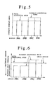
- Fig. 5 is a graph showing the area of contact between the injector housing 2 and the nozzle body 3 in the fan-like regions 24A, 24B, 24C and 24D.
- Fig. 6 is similarly a graph that shows the flatness upon grinding of the first seal surface 24 of the injector housing 2 and of the second seal surface 25 of the nozzle body 3, and that shows the corresponding amount of machining required.
- the formation of the additional hole 6A thus makes it possible to obtain a more uniform seal surface pressure.
- the formation of the additional hole 6A thus makes it possible to make the machining process more uniform.
- micro-recesses 31 (Fig. 2) and the micro-recesses 41 (Fig. 4) can also be formed in the upper face of the nozzle body 3 (second seal surface 25).
- micro-recesses 31 and micro-recesses 41 can be adopted not only for a product comprising a body that connects to a fuel injection nozzle such as the nozzle body 3, but also for a part that connects interlinking high pressure fuel paths such as the first fuel path 13 and the second fuel path 14 to each other, and for a component made of a general material and subjected to general heat treatment in order to provide sealing for high pressure fuel.
- the seal surface pressure can be increased to thus permit greater fuel leak stability.
- Fig. 7 is an enlarged cross-sectional view of the constituent elements of the injector housing 2 section in a fuel path sealing structure 50 for the fuel injection valve 1.
- Fig. 8 is similarly a bottom view of the injector housing 2, wherein the fuel path sealing structure 50 is formed, for example, with a closed circular micro groove 51 that is positioned around the first fuel path 13 in the bottom (first seal surface 24) of the injector housing 2 so that this micro groove 51 surrounds the first fuel path 13.
- the micro groove 51 is formed between the peripheral face of the injector housing 2, and the spring chamber 19 (first sliding hole), and the outermost portion of the micro groove 51 is located at a midway point between the peripheral face of the injector housing 2, and the first fuel path 13.
- the micro groove 51 is formed so as to ensure an equal interval from the first fuel path 13, that is, the circumferential position of the micro groove 51 is established such that the micro groove 51 is concentric with the first fuel path 13, such that the pressure of the high pressure fuel in the first fuel path 13 acts uniformly on the micro groove 51.
- this is a very fine groove whose depth and width are on the order of 0.013 mm, for example, which constitutes a machining minimum for end milling and the like, the micro groove 51 being designed in accordance with the tightening force of the nozzle nut 9 and with the fuel pressure, and the like.
- Fig. 9 is a graph showing relationships between positions on the bottom of the injector housing 2 and the corresponding pressures.
- Fig. 10 is an enlarged cross-sectional view of the constituent elements of the injector housing 2 section in a fuel path sealing structure 60 for a fuel injection valve according to the fourth embodiment.
- Fig. 11 is similarly a bottom view of the injector housing 2, wherein the fuel path sealing structure 60 is formed, for example, with an open circular arc shaped micro groove 61 that is positioned around the first fuel path 13 in the bottom (first seal surface 24) of the injector housing 2 so that this groove 61 surrounds the first fuel path 13. Both ends of the micro groove 61 are able to communicate with the low-pressure side spring chamber 19 (first sliding hole).
- the shape of the arc of the micro groove 61 is optional, and more particularly the outermost portion of the micro groove 61 is located at a midway point between the peripheral face of the injector housing 2, and the first fuel path 13, such that the micro groove 61 is formed so as to be symmetrical with respect to the radial direction of the injector housing 2.
- the dimensions of the micro groove 61 are set at a depth and width that pertain to the machining minimum, for example.
- the fuel which leaks out from the first fuel path 13 to the micro groove 61 can also be returned to the fuel tank 10 via the spring chamber 19, which is a low-pressure side leak path, and via the fuel return line 16.
- Fig. 12 is a bottom view of the injector housing 2 in a fuel path sealing structure 70 section for a fuel injection valve according to the fifth embodiment, wherein the fuel path sealing structure 70 is, for example, formed with a micro groove 71 in the bottom (first seal surface 24) of the injector housing 2.
- This micro groove 71 is constituted from the micro groove 51, which has the same circular shape as that in the fuel path sealing structure 50, and a linking groove 72, which links the micro groove 51 to the spring chamber 19 (leak path).
- the micro groove 71 works similarly to the micro groove 51 shown in Figs. 8 and 9 and is capable of discharging leaking fuel to the spring chamber 19 via the linking groove 72.
- micro groove 51 (Fig. 8), 61 (Fig. 10), and 71 (Fig. 12) according to the embodiments as described above can also be formed in the upper face (the second seal surface 25) of the nozzle body 3.
- this micro groove 51, 61, 71 can be adopted not only for a product comprising a body that connects to a fuel injection nozzle such as the nozzle body 3, but also for a part that connects interlinking high pressure fuel paths such as the first fuel path 13 and the second fuel path 14 to each other, and for a component made of a general material and subjected to general heat treatment in order to provide sealing for high pressure fuel.
- the formation of a micro groove in the seal surface makes secondary sealing possible by causing a stepwise reduction in the fuel pressure, which makes it possible to more reliably prevent a high pressure fuel leak and to improve safety even using an equal seal surface pressure.
- a fuel path sealing structure for a fuel injection valve comprising: a first body, which is formed with a first fuel path for high pressure fuel and comprises a first seal surface that surrounds the first fuel path; and a second body, which comprises a second seal surface facing the first seal surface, and which is formed with a second fuel path that communicates with the first fuel path to enable the high pressure fuel to be supplied to injection holes for the high pressure fuel, wherein slightly shallow micro-recesses are formed over a predetermined surface area of at least either one of the first seal surface of the first body and the second seal surface of the second body, avoiding the first fuel pat, the second fuel path, and the respective periphery of the first body and the second body.
- the micro-recesses are made symmetrical with respect to a straight line that passes through the center of the first and second bodies.
- the mutual alignment of the first body and the second body is determined by means of a locating pin that is inserted in location holes, and the micro-recesses are afforded symmetry by forming, in the seal surfaces, an additional hole which has a diameter that corresponds to that of the location holes.
- the shape of the micro-recesses is afforded symmetry with respect to at least either one of mutually orthogonal straight lines by forming the additional hole on the side opposite the fuel paths.
- a fuel path sealing structure for a fuel injection valve comprising: a first body, which is formed with a first fuel path for high pressure fuel and comprises a first seal surface that surrounds the first fuel path; and a second body, which comprises a second seal surface facing the first seal surface, and which is formed with a second fuel path that communicates with the first fuel path to enable the high pressure fuel to be supplied to injection holes for the high pressure fuel, wherein a micro groove is formed in a position around the first fuel path or the second fuel path in at least either one of the first seal surface of the first body and the second seal surface of the second body.
- the micro groove is afforded a closed circular shape.
- the micro groove is afforded an open circular arc shape and is able to communicate with a leak path different from the fuel paths.
- the micro groove is made circular and is able to communicate with a leak path different from the fuel paths.
- a fuel injection valve provided with a fuel path sealing structure, comprising: a first body, which is formed with a first fuel path for high pressure fuel and comprises a first seal surface that surrounds the first fuel path; and a second body, which comprises a second seal surface facing the first seal surface, and which is formed with a second fuel path that communicates with the first fuel path to enable the high pressure fuel to be supplied to injection holes for the high pressure fuel, wherein slightly shallow micro-recesses are formed over a predetermined surface area of at least either one of the first seal surface of the first body and the second seal surface of the second body, avoiding the first fuel path, the second fuel path, and the respective periphery of the first body and the second body.
- the micro-recesses are made symmetrical with respect to a straight line that passes through the center of the first and second bodies.
- the mutual alignment of the first body and the second body is determined by means of locating pin that is inserted in location holes, and the micro-recesses are afforded symmetry by forming, in the seal surfaces, an additional hole which has a diameter that corresponds to that of the location holes.
- the shape of the micro-recesses is afforded symmetry with respect to at least either one of mutually orthogonal straight lines by forming the additional hole on the side opposite the fuel paths.
- a fuel injection valve provided with a fuel path sealing structure, comprising: a first body, which is formed with a first fuel path for high pressure fuel and comprises a first seal surface that surrounds the first fuel path; and a second body, which comprises a second seal surface facing the first seal surface, and which is formed with a second fuel path that communicates with the first fuel path to enable the high pressure fuel to be supplied to injection holes for the high pressure fuel, wherein a micro groove is formed in a position around the first fuel path or the second fuel path in at least either one of the first seal surface of the first body and the second seal surface of the second body.
- the micro groove is afforded a closed circular shape.
- the micro groove is afforded an open circular arc shape and is able to communicate with a leak path different from the fuel paths.
- the micro groove is made circular and is able to communicate with a leak path different from the fuel paths.
Landscapes
- Engineering & Computer Science (AREA)
- Chemical & Material Sciences (AREA)
- Combustion & Propulsion (AREA)
- Mechanical Engineering (AREA)
- General Engineering & Computer Science (AREA)
- Manufacturing & Machinery (AREA)
- Fuel-Injection Apparatus (AREA)
Abstract
Description
- The present invention relates to a fuel path sealing structure for a fuel injection valve, and more particularly to a fuel path sealing structure for a fuel injection valve that injects, with predetermined timing, high pressure fuel which is supplied via an accumulator (common rail) or the like.
- A conventional fuel injection valve and the fuel path sealing structure thereof will be outlined in accordance with Fig. 13.
- Fig. 13 is a cross-sectional view of the constituent elements of a fuel injection valve 1 which comprises an injector housing 2 (first body), a nozzle body 3 (second body), a
nozzle needle 4, and a back pressure control portion 5. - Two or more
first location holes 6 are formed in theinjector housing 2 and an equal number ofsecond location holes 7 are formed in thenozzle body 3. Theinjector housing 2 andnozzle body 3 are aligned with one another by means of a locating pin 8 that is pushed into thefirst location holes 6 and thesecond location holes 7, and thenozzle body 3 is attached to the tip of theinjector housing 2 by means of anozzle nut 9, the back pressure control portion 5 being provided thereabove. - Fuel from a
fuel tank 10 is pressurized to a high pressure by afuel pump 11 and accumulates in a common rail 12 (accumulator), and high pressure fuel is supplied to the fuel injection valve 1. - In other words, a
first fuel path 13 is formed in theinjector housing 2 and asecond fuel path 14 is formed in thenozzle body 3, and afuel reservoir 15 is formed facing apressure receiver 4A of thenozzle needle 4, such that high pressure fuel can be continually supplied to thefuel reservoir 15 from thecommon rail 12. - Furthermore, a
fuel return line 16 is formed from the section of the back pressure control portion 5 by extending a portion of thefirst fuel path 13 toward the top of the figure, which permits the return of fuel to thefuel tank 10. Thefuel return line 16 forms a fuel leak path together with a spring chamber 19 (first sliding hole) and the like that will be described subsequently. - The
nozzle body 3 has an arbitrary number offuel injection holes 17 formed at the tip thereof. Theinjection holes 17 are closed when the tip of thenozzle needle 4 is seated at theseat portion 18 that is linked with theinjection holes 17, and theinjection holes 17 are opened to thus permit the injection of fuel when the nozzle needle 4 lifts from theseat portion 18. - The spring chamber 19 (first sliding hole) is formed at the center of the
injector housing 2 and above thenozzle needle 4, and provided in thespring chamber 19 are aspring seat 20, anozzle spring 21, which biases thenozzle needle 4 toward theseat portion 18 in the seating direction, and avalve piston 22, which abuts against thespring seat 20 from above. - The back pressure control portion 5 controls the
valve piston 22, that is, controls the seating and lifting of thenozzle needle 4 via thespring seat 20 by controlling the back pressure on thenozzle needle 4. - The upper portion of the
nozzle needle 4 is capable of sliding in a clearance seal hole 23 (second sliding hole) of thenozzle body 3. Thespring chamber 19 communicates with the low-pressure sidefuel return line 16 and thenozzle body 3 separates a high-pressure side (fuel reservoir chamber 15) in theclearance seal hole 23 of thenozzle body 3 and the low-pressure side (spring chamber 19). - The
injector housing 2 comprises afirst seal surface 24 that is at the bottom of theinjector housing 2 and lies orthogonal to the longitudinal direction of theinjector housing 2. Thenozzle body 3 has asecond seal surface 25 at the top thereof that lies orthogonal to the longitudinal direction of thenozzle body 3. - The
first seal surface 24 andsecond seal surface 25 ensure a predetermined surface pressure as a result of tightening thenozzle nut 9 using a predetermined seat tightening force. A highpressure seal surface 26 is formed between thefirst seal surface 24 andsecond seal surface 25 such that no fuel leaks to outside the fuel injection valve 1 from thefirst fuel path 13 and thesecond fuel path 14 through which high pressure fuel passes. The occurrence of a fuel leak causes problems such as that of the invasion of fuel into the engine oil, which produces a reduction in lubricity. - Fig. 14 is a bottom view of the section of the
injector housing 2, and illustrates the relative positions of thefirst fuel path 13 and a pair offirst location holes 6. - That is, as shown in the figure, the pair of
first location holes 6 are formed in positions that have lateral symmetry with respect to the straight line X joining thecenter 19C of the spring chamber 19 (injector housing 2) and thecenter 13C of thefirst fuel path 13. - In a fuel injection valve 1 having such a constitution, the sealing is generally improved by increasing the tightening force of the
nozzle nut 9 at the highpressure seal surface 26 formed by thefirst seal surface 24 and thesecond seal surface 25. - However, when the internal pressure of the
first fuel path 13 and thesecond fuel path 14 becomes significantly high, such pressure is difficult to handle by means of a simple increase in the tightening force of thenozzle nut 9, and even if additional improvements are made to the existing material and heat treatment and the like of theinjector housing 2 andnozzle body 3, problems arise, namely that the material strength places restrictions on the permissible surface pressure at the highpressure seal surface 26 and there is the danger of a fuel leak. - More particularly, the fuel injection valve 1, which is of a type that has a
common rail 12, is different from a conventional jerk-type fuel injection valve and has a different nozzle body. Because a rail pressure is applied from thecommon rail 12 to the high pressure section of the nozzle body (namely thefirst fuel path 13,second fuel path 14 and fuel reservoir 15), there is a requirement to increase the seal surface pressure of the highpressure seal surface 26 in line with high pressure injection. Because a fuel leak from this highpressure seal surface 26 involves a fuel leak to outside the fuel injection valve 1, a reliable seal is required. - Documents relating to this kind of fuel injection valve include
Japanese Patent Application Laid-Open No. H7-317631 Japanese Patent Application Laid-Open No. H8-165965 Japanese Patent Application Laid-Open No. H9-242649 - The present invention was conceived in view of the aforementioned problems, and has as an objective to provide a fuel path sealing structure for a fuel injection valve adapted so as to reliably prevent a fuel leak by increasing the seal surface pressure between a first body such as an injector housing, and a second body such as a nozzle body.
- A further objective of the present invention is to provide a fuel path sealing structure for a fuel injection valve that permits an increase in the seal surface pressure without a change to the size of the nozzle nut or the corresponding tightening force.
- Yet another objective of the present invention is to provide a fuel path sealing structure for a fuel injection valve that makes uniform the joining surface of the seal surfaces to thereby stabilize the surface pressure distribution and increase the safety against a fuel leak by means of a reliable target surface pressure.
- Yet another objective of the present invention is to provide a fuel path sealing structure for a fuel injection valve that permits an increase in the seal performance of the fuel path section without affecting the fuel injection valve or engine performance.
- Yet another objective of the present invention is to provide a fuel path sealing structure for a fuel injection valve that is capable of preventing a leak of high pressure fuel using simple means without making any substantial changes to a conventional fuel injection valve, more particularly to the injector housing, nozzle body, and the like.
- Yet another objective of the present invention is to provide a fuel path sealing structure for a fuel injection valve that is capable of preventing a fuel leak by increasing the seal performance between a first body such as an injector housing and a second body such as a nozzle body.
- Yet another objective of the present invention is to provide a fuel path sealing structure for a fuel injection valve that prevents a fuel leak and permits an increase in stability, using means other than means for increasing the seal surface pressure, that is, even if the seal surface pressure is the same and the fuel pressure is a higher pressure.
- According to the present invention, said objectives are solved by the combination of features of independent claim 1.
- A preferred embodiment directed toward the formation over a predetermined surface area, in the seal surface between a first body such as an injector housing and a second body such as a nozzle body, of slightly shallow micro-recesses, in regions other than the high pressure fuel path and the periphery of the seal surface, that is, at the center of the seal surface. The embodiment is a fuel path sealing structure for a fuel injection valve, comprising: a first body, which is formed with a first fuel path for high pressure fuel and comprises a first seal surface that surrounds the first fuel path; and a second body, which comprises a second seal surface facing the first seal surface, and which is formed with a second fuel path that communicates with the first fuel path to enable the high pressure fuel to be supplied to injection holes for the high pressure fuel, wherein slightly shallow micro-recesses are formed over a predetermined surface area of at least either one of the first seal surface of the first body and the second seal surface of the second body, avoiding the first fuel path, the second fuel path, and the respective periphery of the first body and the second body.
- Preferably, the micro-recesses can be made symmetrical with respect to a straight line that passes through the center of the first and second bodies. The straight line passing through the center of the bodies may be preferably a straight line that follows the radial direction of the bodies or a straight line in the axial direction thereof, and the symmetry may be linear symmetry or rotational symmetry.
- Preferably, the mutual alignment of the first body and the second body can be determined by means of a locating pin that is inserted in location holes, and the micro-recesses can be afforded symmetry by forming, in the seal surfaces, an additional hole which has a diameter that corresponds to that of the location holes.
- Preferably, the shape of the micro-recesses can be afforded symmetry with respect to at least either one of mutually orthogonal straight lines by forming the additional hole on the side opposite the fuel paths.
- In the fuel path sealing structure for a fuel injection valve according to the preferred embodiment, due to the formation over a predetermined surface area, in the seal surface between a first body such as an injector housing and a second body such as a nozzle body, of slightly shallow micro-recesses, in regions other than the high pressure fuel path and the periphery of the seal surface, when the first body and the second body are brought into intimate contact with one another by means of a predetermined tightening torque, the intimate contact area is smaller than that of the prior art, and it is therefore possible to improve the seal performance by increasing the seal surface pressure even when using an equal tightening torque.
- If an additional hole that has a diameter equal to that of the location holes is formed and the shape of the micro-recesses can be made symmetrical with respect to mutually orthogonal straight lines, the intimate contact pressure of the joining surface can be made uniform over the whole seal surface whereby increased fuel leak stability is permitted.
- Another preferred embodiment is further directed toward the formation of a fine groove (micro groove) around the high pressure oil paths (fuel paths) in the injector housing and nozzle body, and the like, and toward the secondary sealing of leaking fuel that, upon leaking from the fuel path, subsequently exhibits a pressure drop. The preferred embodiment is a fuel path sealing structure for a fuel injection valve, comprising: a first body such as an injector housing, which is formed with a first fuel path for high pressure fuel and comprises a first seal surface that surrounds the first fuel path; and a second body such as a nozzle body, which comprises a second seal surface facing the first seal surface, and which is formed with a second fuel path that communicates with the first fuel path to enable the high pressure fuel to be supplied to injection holes for the high pressure fuel, characterized in that a micro groove is formed in a position around the first fuel path or the second fuel path in at least either one of the first seal surface of the first body and the second seal surface of the second body.
- Preferably, the micro groove can be afforded a closed circular shape.
- Preferably, the micro groove can be afforded an open circular arc shape and can be made able to communicate with a leak path different from the fuel paths.
- Preferably, the micro groove can be made circular and can be made able to communicate with a leak path different from the fuel paths.
- In addition to the injector housing and the nozzle body, and the like, the fuel path sealing structure of the embodiment can be preferably adopted for parts requiring a reliable sealing of high pressure fuel via a seal surface.
- In the fuel path sealing structure for a fuel injection valve according to the embodiment, a fine groove (micro groove) is formed around the fuel path in a first body such as an injector housing and a second body such as a nozzle body. It is therefore possible to provide secondary sealing at the seal surfaces of leaking fuel that, upon leaking on the high pressure side, subsequently exhibits a pressure drop, such that, irrespective of whether there is any kind of increase in the seal surface pressure of the high pressure seal surface section, a fuel leak to the outside from the first fuel path and second fuel path section can be avoided and the reliability of the fuel injection valve can therefore be ensured.
- Moreover, on account of the simple constitution, which merely involves the formation of a micro groove in the seal surface of the first body or second body, the embodiment can be implemented by the straightforward machining of an existing injector housing or nozzle body.
- Further preferred embodiments are laid down in the further subclaims.
- In the following, the present invention is explained in greater detail by means of embodiments thereof in conjunction with the accompanying drawings, wherein:
- Fig. 1 is an enlarged cross-sectional view of the constituent elements of the
injector housing 2 section in a fuelpath sealing structure 30 for a fuel injection valve according to a first embodiment; - Fig. 2 is similarly a bottom view of the
injector housing 2; - Fig. 3 is an enlarged cross-sectional view of the constituent elements of the
injector housing 2 section in a fuelpath sealing structure 40 for a fuel injection valve according to a second embodiment; - Fig. 4 is similarly a bottom view of the
injector housing 2; - Fig. 5 is similarly a graph showing the area of contact between the
injector housing 2 and thenozzle body 3 in the fan-like regions - Fig. 6 is similarly a graph that shows the flatness upon grinding of the
first seal surface 24 of theinjector housing 2 and of thesecond seal surface 25 of thenozzle body 3, and that shows the corresponding machining amount required; - Fig. 7 is an enlarged cross-sectional view of the constituent elements of the
injector housing 2 section in a fuelpath sealing structure 50 for a fuel injection valve according to the third embodiment; - Fig. 8 is similarly a bottom view of the
injector housing 2; - Fig. 9 is similarly a graph showing relationships between positions on the bottom of the
injector housing 2 and the corresponding pressures; - Fig. 10 is an enlarged cross-sectional view of the constituent elements of the
injector housing 2 section in a fuelpath sealing structure 60 for a fuel injection valve according to the fourth embodiment; - Fig. 11 is similarly a bottom view of the
injector housing 2; - Fig. 12 is a bottom view of the
injector housing 2 in a fuelpath sealing structure 70 section for a fuel injection valve according to the fifth embodiment; - Fig. 13 is a cross-sectional view of the constituent elements of a conventional fuel injection valve 1; and
- Fig. 14 is similarly a bottom view of the
injector housing 2 section. - A description will be provided next of the fuel
path sealing structure 30 for a fuel injection valve according to the first embodiment,
in accordance with Figs. 1 and 2. However, those parts which are the same as those in Figs. 13 and 14 have been assigned the same reference numerals, and a detailed description thereof is thus omitted here. - Fig. 1 is an enlarged cross-sectional view of the constituent elements of the
injector housing 2 section in a fuelpath sealing structure 30 for a fuel injection valve 1. Fig. 2 is similarly a bottom view of theinjector housing 2, wherein the fuelpath sealing structure 30 has very shallow micro-recesses 31 formed symmetrically in a predetermined shape and area in the bottom of the injector housing 2 (the first seal surface 24), in regions other than thefirst fuel path 13, theperiphery 2A of the injector housing 2 (that is, the periphery of thefirst seal surface 24 and the second seal surface 25), and a pair of first location holes 6. - In other words, the micro-recesses 31 lie between the
periphery 2A of theinjector housing 2, and the spring chamber 19 (first sliding hole), and the outermost portion of these recesses does not reach and avoids thefirst fuel path 13, the pair offirst location holes 6 and theperiphery 2A of theinjector housing 2. The micro-recesses 31 are formed around thespring chamber 19 and so as to be symmetrical with respect to the straight line X that passes through thecenter 19C of thespring chamber 19 and thecenter 13C of thefirst fuel path 13. - Furthermore, the micro-recesses 31 are constituted from the radial recesses 31A, 31B, 31C and 31D which are respectively positioned in fan-
like regions center 19C, theseradial recesses center 19C. - Accordingly, the
first seal surface 24 comprises the above-described substantially radial micro-recesses 31, and a pressurecontact seal surface 32 which excludes the micro-recesses 31 and which surrounds the micro-recesses 31 in thefirst seal surface 24, wherein thefirst fuel path 13 and the pair offirst location holes 6 are positioned as openings in the pressurecontact seal surface 32. - With regard to the size of the micro-recesses 31, these are very fine recesses whose depth is on the order of 0.013 mm, for example, which constitutes a machining minimum for end milling and the like, these
micro-recesses 31 being designed in accordance with the tightening force of thenozzle nut 9 and with the fuel pressure, and so forth. - In the fuel
path sealing structure 30 for a fuel injection valve which is thus constituted, thefirst seal surface 24 of theinjector housing 2 and thesecond seal surface 25 of thenozzle body 3 lie in intimate contact with one another to thereby form a highpressure seal surface 26 as a result of clamping theinjector housing 2 and thenozzle body 3 by means of a predetermined axial tightening force imparted by thenozzle nut 9. Of thefirst seal surface 24 and thesecond seal surface 25, because only the section constituted by the pressurecontact seal surface 32 that has a smaller surface area contacts thesecond seal surface 25 under pressure, the seal surface pressure is increased beyond that of the prior art, which permits an increase in the seal performance of thefirst fuel path 13 andsecond fuel path 14 section even if an equal tightening torque is applied. - In addition, because the micro-recesses 31 are made symmetrical with respect to the straight line X, the balance of the seal surface pressure is made even. It is thus possible to increase the safety against fuel leak, and programmed machining by means of end milling and the like is straightforward. It is thus possible to deal with fuel leaks that accompany the high pressurization of fuel by means of a simple constitution.
- The micro-recesses 31 can also be made symmetrical with respect to the straight line Y in addition to the straight line X (line symmetry) and can also be made symmetrical about a straight line that is orthogonal to the straight line X and straight line Y (a straight line that passes through the
center 19C of thespring chamber 19, that is, the center of the bodies of theinjector housing 2 and thenozzle body 3, and the like) (rotational symmetry). - Fig. 3 is an enlarged cross-sectional view of the constituent elements of the
injector housing 2 section in a fuelpath sealing structure 40 for a fuel injection valve according to the second embodiment. - Fig. 4 is similarly a bottom view of the
injector housing 2, wherein the fuelpath sealing structure 40 has micro-recesses 41 of greater symmetry than that of the fuel path sealing structure 30 (Fig. 2) which are formed in the first seal surface 24 (bottom) of theinjector housing 2, and, in addition to the pair of first location holes 6, the fuelpath sealing structure 40 is formed with anadditional hole 6A that is of the same diameter as thefirst location holes 6 and is formed on the opposite side of thefirst fuel path 13. - That is, the micro-recesses 41 are symmetrical with respect to the straight line X, and are constituted from the fan-
like recesses like regions - The
additional hole 6A lies on the straight line X on the opposite side to thefirst fuel path 13 and is located at a midway point between the other pair of first location holes 6. - Further, the location and size of the
additional hole 6A are determined in accordance with the location, shape, and size of the micro-recesses 41, and the corresponding fan-like recesses like regions - Naturally, like the micro-recesses 31, the micro-recesses 41 can also be made symmetrical with respect to the straight line Y in addition to the straight line X (line symmetry) and can also be made symmetrical about a straight line that is orthogonal to the straight line X and straight line Y (a straight line that passes through the
center 19C of thespring chamber 19, that is, the center of the bodies of theinjector housing 2 and thenozzle body 3, and the like) (rotational symmetry). - Therefore, the
first seal surface 24 is constituted from the above-described substantially circular or hourglass-shaped micro-recesses 41, and a pressurecontact seal surface 42 which excludes the micro-recesses 41 and surrounds the micro-recesses 41 in thefirst seal surface 24, wherein thefirst fuel path 13 and theadditional hole 6A are located in the pressurecontact seal surface 42 and the other pair offirst location holes 6 are located in the micro-recesses 41. - Like the fuel
path sealing structure 30 shown in Figs. 1 and 2, in the fuelpath sealing structure 40 for a fuel injection valve thus constituted, thefirst seal surface 24 of theinjector housing 2 and thesecond seal surface 25 of thenozzle body 3 lie in intimate contact with one another to thereby form a highpressure seal surface 26 as a result of clamping theinjector housing 2 and thenozzle body 3 by means of a predetermined axial tightening force imparted by thenozzle nut 9. Of thefirst seal surface 24 and thesecond seal surface 25, because only the section constituted by the pressurecontact seal surface 42 that has a smaller surface area contacts thesecond seal surface 25 under pressure, the seal surface pressure is increased beyond that of the prior art, which permits an increase in the seal performance of thefirst fuel path 13 andsecond fuel path 14 section even if an equal tightening torque is applied. - Furthermore, because the micro-recesses 41 are made symmetrical with respect to the straight line X, and micro-recesses 41 form a nearly symmetrical shape also with respect to the straight line Y, the balance of the seal surface pressure at the
first seal surface 24 is made even more even, thus permitting an increase in the safety against fuel leak, and programmed machining by means of end milling and the like is straightforward. It is thus possible to deal with fuel leaks that accompany the high pressurization of fuel by means of a simple constitution. - Fig. 5 is a graph showing the area of contact between the
injector housing 2 and thenozzle body 3 in the fan-like regions first seal surface 24 of theinjector housing 2 and of thesecond seal surface 25 of thenozzle body 3, and that shows the corresponding amount of machining required. - As shown in Fig. 5, when there is no
additional hole 6A (dotted line), the area of contact of the fan-like regions like regions additional hole 6A is present (solid line). - The formation of the
additional hole 6A thus makes it possible to obtain a more uniform seal surface pressure. - Also, as shown in Fig. 6, in comparison with a case where the
additional hole 6A is present (solid line), in the absence of theadditional hole 6A (dotted line), it is necessary to reduce the contact area by making the flatness upon grinding of the fan-like regions like regions additional hole 6A is present (solid line), the machining amount of the seal surfaces 24 and 25 is made uniform and the mean height can be made substantially uniform. - The formation of the
additional hole 6A thus makes it possible to make the machining process more uniform. - The above-described micro-recesses 31 (Fig. 2) and the micro-recesses 41 (Fig. 4) can also be formed in the upper face of the nozzle body 3 (second seal surface 25).
- In addition, the micro-recesses 31 and
micro-recesses 41 can be adopted not only for a product comprising a body that connects to a fuel injection nozzle such as thenozzle body 3, but also for a part that connects interlinking high pressure fuel paths such as thefirst fuel path 13 and thesecond fuel path 14 to each other, and for a component made of a general material and subjected to general heat treatment in order to provide sealing for high pressure fuel. - According to the embodiments described above (the first invention), due to the formation of the micro-recesses which serve to avoid mutual contact at the center at the seal surfaces of the injector housing or the nozzle body, the seal surface pressure can be increased to thus permit greater fuel leak stability.
- A description will be provided next, in accordance with Figs. 7 through 9, of a fuel
path sealing structure 50 for a fuel injection valve according to the third embodiment. - Fig. 7 is an enlarged cross-sectional view of the constituent elements of the
injector housing 2 section in a fuelpath sealing structure 50 for the fuel injection valve 1. Fig. 8 is similarly a bottom view of theinjector housing 2, wherein the fuelpath sealing structure 50 is formed, for example, with a closed circularmicro groove 51 that is positioned around thefirst fuel path 13 in the bottom (first seal surface 24) of theinjector housing 2 so that thismicro groove 51 surrounds thefirst fuel path 13. - The
micro groove 51 is formed between the peripheral face of theinjector housing 2, and the spring chamber 19 (first sliding hole), and the outermost portion of themicro groove 51 is located at a midway point between the peripheral face of theinjector housing 2, and thefirst fuel path 13. Themicro groove 51 is formed so as to ensure an equal interval from thefirst fuel path 13, that is, the circumferential position of themicro groove 51 is established such that themicro groove 51 is concentric with thefirst fuel path 13, such that the pressure of the high pressure fuel in thefirst fuel path 13 acts uniformly on themicro groove 51. - With regard to the size of the
micro groove 51, this is a very fine groove whose depth and width are on the order of 0.013 mm, for example, which constitutes a machining minimum for end milling and the like, themicro groove 51 being designed in accordance with the tightening force of thenozzle nut 9 and with the fuel pressure, and the like. - In the fuel
path sealing structure 50 for a fuel injection valve which is thus constituted, a leak of high pressure fuel from thefirst fuel path 13 andsecond fuel path 14 can be more reliably prevented. - That is, Fig. 9 is a graph showing relationships between positions on the bottom of the
injector housing 2 and the corresponding pressures. Even in the event that the fuel pressure (solid line) is larger than the seal surface pressure (dotted line) at the position P0 on the circumference of thefirst fuel path 13 and there occurs a fuel leak in the peripheral direction of thefirst fuel path 13, due to the drop in pressure of leaking fuel at the position P1 on the inner circumference of themicro groove 51, the seal surface pressure is then greater than the fuel pressure and secondary sealing is thus made possible by ensuring that the seal surface pressure at the position P2 on the outer circumference of themicro groove 51 is greater than the fuel pressure. A fuel leak in the peripheral direction of theinjector housing 2 and outside the fuel injection valve 1 can thus be prevented. - Fig. 10 is an enlarged cross-sectional view of the constituent elements of the
injector housing 2 section in a fuelpath sealing structure 60 for a fuel injection valve according to the fourth embodiment. - Fig. 11 is similarly a bottom view of the
injector housing 2, wherein the fuelpath sealing structure 60 is formed, for example, with an open circular arc shapedmicro groove 61 that is positioned around thefirst fuel path 13 in the bottom (first seal surface 24) of theinjector housing 2 so that thisgroove 61 surrounds thefirst fuel path 13. Both ends of themicro groove 61 are able to communicate with the low-pressure side spring chamber 19 (first sliding hole). - The shape of the arc of the
micro groove 61 is optional, and more particularly the outermost portion of themicro groove 61 is located at a midway point between the peripheral face of theinjector housing 2, and thefirst fuel path 13, such that themicro groove 61 is formed so as to be symmetrical with respect to the radial direction of theinjector housing 2. - Like the micro groove 51 (Fig. 7 and Fig. 8), the dimensions of the
micro groove 61 are set at a depth and width that pertain to the machining minimum, for example. - In a fuel
path sealing structure 60 for a fuel injection valve which is thus constituted, the fuel which leaks out from thefirst fuel path 13 to themicro groove 61 can also be returned to thefuel tank 10 via thespring chamber 19, which is a low-pressure side leak path, and via thefuel return line 16. - It is thus possible to prevent fuel from leaking outside the fuel injection valve 1, that is, outside the engine, by returning leaking fuel to the
fuel return line 16, which makes it possible to prevent an offensive odor and a fire, and the like. The amount of fuel that leaks out to thefuel return line 16 is extremely small and does not affect the product performance. - Fig. 12 is a bottom view of the
injector housing 2 in a fuelpath sealing structure 70 section for a fuel injection valve according to the fifth embodiment,
wherein the fuelpath sealing structure 70 is, for example, formed with amicro groove 71 in the bottom (first seal surface 24) of theinjector housing 2. - This
micro groove 71 is constituted from themicro groove 51, which has the same circular shape as that in the fuelpath sealing structure 50, and a linkinggroove 72, which links themicro groove 51 to the spring chamber 19 (leak path). - In the fuel
path sealing structure 70 for a fuel injection valve thus constituted, themicro groove 71 works similarly to themicro groove 51 shown in Figs. 8 and 9 and is capable of discharging leaking fuel to thespring chamber 19 via the linkinggroove 72. - The micro groove 51 (Fig. 8), 61 (Fig. 10), and 71 (Fig. 12) according to the embodiments as described above can also be formed in the upper face (the second seal surface 25) of the
nozzle body 3. - In addition, this
micro groove nozzle body 3, but also for a part that connects interlinking high pressure fuel paths such as thefirst fuel path 13 and thesecond fuel path 14 to each other, and for a component made of a general material and subjected to general heat treatment in order to provide sealing for high pressure fuel. - According to the embodiments above, the formation of a micro groove in the seal surface makes secondary sealing possible by causing a stepwise reduction in the fuel pressure, which makes it possible to more reliably prevent a high pressure fuel leak and to improve safety even using an equal seal surface pressure.
- The description above discloses (among others) an embodiment of a fuel path sealing structure for a fuel injection valve, comprising: a first body, which is formed with a first fuel path for high pressure fuel and comprises a first seal surface that surrounds the first fuel path; and a second body, which comprises a second seal surface facing the first seal surface, and which is formed with a second fuel path that communicates with the first fuel path to enable the high pressure fuel to be supplied to injection holes for the high pressure fuel, wherein slightly shallow micro-recesses are formed over a predetermined surface area of at least either one of the first seal surface of the first body and the second seal surface of the second body, avoiding the first fuel pat, the second fuel path, and the respective periphery of the first body and the second body.
- Preferably, the micro-recesses are made symmetrical with respect to a straight line that passes through the center of the first and second bodies.
- Preferably, the mutual alignment of the first body and the second body is determined by means of a locating pin that is inserted in location holes, and the micro-recesses are afforded symmetry by forming, in the seal surfaces, an additional hole which has a diameter that corresponds to that of the location holes.
- Further preferably, the shape of the micro-recesses is afforded symmetry with respect to at least either one of mutually orthogonal straight lines by forming the additional hole on the side opposite the fuel paths.
- The description above also discloses an embodiment of a fuel path sealing structure for a fuel injection valve, comprising: a first body, which is formed with a first fuel path for high pressure fuel and comprises a first seal surface that surrounds the first fuel path; and a second body, which comprises a second seal surface facing the first seal surface, and which is formed with a second fuel path that communicates with the first fuel path to enable the high pressure fuel to be supplied to injection holes for the high pressure fuel, wherein a micro groove is formed in a position around the first fuel path or the second fuel path in at least either one of the first seal surface of the first body and the second seal surface of the second body.
- Preferably, the micro groove is afforded a closed circular shape.
- Preferably, the micro groove is afforded an open circular arc shape and is able to communicate with a leak path different from the fuel paths.
- Preferably, the micro groove is made circular and is able to communicate with a leak path different from the fuel paths.
- The description also discloses an aspect of a fuel injection valve provided with a fuel path sealing structure, comprising: a first body, which is formed with a first fuel path for high pressure fuel and comprises a first seal surface that surrounds the first fuel path; and a second body, which comprises a second seal surface facing the first seal surface, and which is formed with a second fuel path that communicates with the first fuel path to enable the high pressure fuel to be supplied to injection holes for the high pressure fuel, wherein slightly shallow micro-recesses are formed over a predetermined surface area of at least either one of the first seal surface of the first body and the second seal surface of the second body, avoiding the first fuel path, the second fuel path, and the respective periphery of the first body and the second body.
- According to a preferred aspect, the micro-recesses are made symmetrical with respect to a straight line that passes through the center of the first and second bodies.
- According to a further preferred aspect, the mutual alignment of the first body and the second body is determined by means of locating pin that is inserted in location holes, and the micro-recesses are afforded symmetry by forming, in the seal surfaces, an additional hole which has a diameter that corresponds to that of the location holes.
- According to another preferred aspect, the shape of the micro-recesses is afforded symmetry with respect to at least either one of mutually orthogonal straight lines by forming the additional hole on the side opposite the fuel paths.
- The description above also discloses an aspect of a fuel injection valve provided with a fuel path sealing structure, comprising: a first body, which is formed with a first fuel path for high pressure fuel and comprises a first seal surface that surrounds the first fuel path; and a second body, which comprises a second seal surface facing the first seal surface, and which is formed with a second fuel path that communicates with the first fuel path to enable the high pressure fuel to be supplied to injection holes for the high pressure fuel, wherein a micro groove is formed in a position around the first fuel path or the second fuel path in at least either one of the first seal surface of the first body and the second seal surface of the second body.
- According to a preferred aspect, the micro groove is afforded a closed circular shape.
- According to a further preferred aspect, the micro groove is afforded an open circular arc shape and is able to communicate with a leak path different from the fuel paths.
- According to another preferred aspect, the micro groove is made circular and is able to communicate with a leak path different from the fuel paths.
Claims (9)
- Fuel path sealing structure (50, 60, 70) for a fuel injection valve, comprising:a first body, which is formed with a first fuel path (13) for high pressure fuel and comprises a first seal surface (24) that surrounds the first fuel path (13); anda second body, which comprises a second surface (25) facing the first seal surface (24), and which is formed with a second fuel path (14) that communicates with the first fuel path (13) to enable the high pressure fuel to be supplied to injection holes for the high pressure fuel,wherein a micro groove (51, 61, 71) is formed in a position around the first fuel path (13) or the second fuel path (14) in at least either one of the first seal surface (24) of the first body and the second seal surface (23) of the second body.
- Fuel path sealing structure for a fuel injection valve according to claim 1, wherein the micro groove (51, 61, 71) is formed symmetrical with respect to a radial direction of the first or second body.
- Fuel path sealing structure for a fuel injection valve according to claim 1 or 2, wherein an outermost portion of the micro groove (51, 61) is located at a midway point between a peripheral face of the first or second body and the first or second fuel path (13, 14).
- Fuel path sealing structure for a fuel injection valve according to at least one of claims 1 to 3, wherein the first body comprises a first sliding hole (19) in its center, and the second body comprises a second sliding hole (23) communicated thereto, and
the micro groove (51, 61, 71) is formed between a peripheral face of the first or second body and the first or second sliding hole (19, 23). - Fuel path sealing structure for a fuel injection valve according to at least one of claims 1 to 4, wherein the micro groove (51) is afforded a closed circular shape.
- Fuel path sealing structure for a fuel injection valve according to at least one of claims 1 to 4, wherein the micro groove (61) is afforded an open circular arc shape and is able to communicate with a leak path different from the fuel paths (13, 14).
- Fuel path sealing structure for a fuel injection valve according to at least one of claims 1 to 4, wherein the micro groove (71) is made circular and is able to communicate with a leak path different from the fuel paths (13, 14).
- Fuel path sealing structure for a fuel injection valve according to claim 7, wherein a linking groove (72) is provided between the micro groove (71) and the leak path.
- Fuel path sealing structure for a fuel injection valve according to at least one of claims 1 to 8, wherein a low-pressure side spring chamber (19) is arranged in the center of the first body so as to form a leak path.
Applications Claiming Priority (3)
| Application Number | Priority Date | Filing Date | Title |
|---|---|---|---|
| JP2001338402A JP3864328B2 (en) | 2001-11-02 | 2001-11-02 | Fuel passage seal structure of fuel injection valve |
| JP2001338403A JP2003139015A (en) | 2001-11-02 | 2001-11-02 | Fuel passage sealing structure for fuel injection valve |
| EP02802385A EP1447559B1 (en) | 2001-11-02 | 2002-10-31 | Fuel passage sealing structure of fuel injection nozzle |
Related Parent Applications (1)
| Application Number | Title | Priority Date | Filing Date |
|---|---|---|---|
| EP02802385A Division EP1447559B1 (en) | 2001-11-02 | 2002-10-31 | Fuel passage sealing structure of fuel injection nozzle |
Publications (2)
| Publication Number | Publication Date |
|---|---|
| EP1744053A1 true EP1744053A1 (en) | 2007-01-17 |
| EP1744053B1 EP1744053B1 (en) | 2008-09-17 |
Family
ID=26624327
Family Applications (2)
| Application Number | Title | Priority Date | Filing Date |
|---|---|---|---|
| EP06023055A Expired - Lifetime EP1744053B1 (en) | 2001-11-02 | 2002-10-31 | Fuel path sealing structure |
| EP02802385A Expired - Lifetime EP1447559B1 (en) | 2001-11-02 | 2002-10-31 | Fuel passage sealing structure of fuel injection nozzle |
Family Applications After (1)
| Application Number | Title | Priority Date | Filing Date |
|---|---|---|---|
| EP02802385A Expired - Lifetime EP1447559B1 (en) | 2001-11-02 | 2002-10-31 | Fuel passage sealing structure of fuel injection nozzle |
Country Status (6)
| Country | Link |
|---|---|
| US (1) | US20050001071A1 (en) |
| EP (2) | EP1744053B1 (en) |
| KR (1) | KR100679359B1 (en) |
| CN (1) | CN1578876A (en) |
| DE (2) | DE60229012D1 (en) |
| WO (1) | WO2003038274A1 (en) |
Cited By (1)
| Publication number | Priority date | Publication date | Assignee | Title |
|---|---|---|---|---|
| WO2009040215A1 (en) * | 2007-09-24 | 2009-04-02 | Robert Bosch Gmbh | Sealing geometry for injectors |
Families Citing this family (10)
| Publication number | Priority date | Publication date | Assignee | Title |
|---|---|---|---|---|
| DE102005004069A1 (en) * | 2005-01-28 | 2006-08-03 | Volkswagen Mechatronic Gmbh & Co. Kg | Injection device e.g. pump-nozzle-injection device, for e.g. diesel engine, has sealing arrangement with O-rings to effect sealing of interface, which includes sealing surface with grooves to accommodate O-rings, at cavity or channel |
| JP4380549B2 (en) * | 2005-01-31 | 2009-12-09 | 株式会社デンソー | Fuel injection valve |
| WO2006135085A1 (en) * | 2005-06-15 | 2006-12-21 | Bosch Corporation | High-pressure seal structure, processing method for high-pressure seal surface, and fuel injection valve |
| JP2007040243A (en) * | 2005-08-04 | 2007-02-15 | Denso Corp | High pressure fuel seal structure of fuel injection device |
| DE102007009166A1 (en) * | 2007-02-26 | 2008-08-28 | Robert Bosch Gmbh | Fuel injector comprises mounting body and nozzle body and other fluid impinging components, which forms screw connection for connecting nozzle tensioning bolt and surface exposure is performed at surface side of mounting body |
| JP4618307B2 (en) * | 2008-03-06 | 2011-01-26 | 株式会社デンソー | Fuel injection valve |
| DE102014220364A1 (en) * | 2014-10-08 | 2016-04-14 | Ksb Aktiengesellschaft | rotary pump |
| GB2549094A (en) * | 2016-04-04 | 2017-10-11 | Delphi Int Operations Luxembourg Sarl | Fuel injector |
| DE102020102194A1 (en) * | 2020-01-30 | 2021-08-05 | Man Energy Solutions Se | Fuel injector |
| US12460820B1 (en) | 2025-04-28 | 2025-11-04 | Solar Turbines Incorporated | Fueling passage array sealing system and method of use |
Citations (4)
| Publication number | Priority date | Publication date | Assignee | Title |
|---|---|---|---|---|
| JPH08270530A (en) * | 1995-03-30 | 1996-10-15 | Zexel Corp | Seat structure of delivery valve seat in fuel injection pump |
| GB2338515A (en) * | 1998-06-20 | 1999-12-22 | Daimler Chrysler Ag | I.c engine fuel injection valve with raised contact surface for leak-tightness between body parts |
| WO2000060233A1 (en) * | 1999-03-31 | 2000-10-12 | Siemens Aktiengesellschaft | Fuel injector for an internal combustion engine |
| EP1288486A2 (en) * | 2001-09-04 | 2003-03-05 | Robert Bosch Gmbh | Leakage channel in a high-pressure fuel system |
Family Cites Families (5)
| Publication number | Priority date | Publication date | Assignee | Title |
|---|---|---|---|---|
| JPS6042351B2 (en) * | 1978-11-07 | 1985-09-21 | 株式会社豊田中央研究所 | Reflux type volute injection valve |
| US4280659A (en) * | 1979-07-23 | 1981-07-28 | Cummins Engine Company, Inc. | Fuel injector |
| JPH0377064U (en) * | 1989-11-29 | 1991-08-01 | ||
| DE19608575B4 (en) * | 1996-03-06 | 2005-10-20 | Bosch Gmbh Robert | Fuel injection valve for internal combustion engines |
| JP3928362B2 (en) * | 2001-02-14 | 2007-06-13 | 株式会社デンソー | Structure to improve seal surface pressure of fluid transfer device |
-
2002
- 2002-10-31 EP EP06023055A patent/EP1744053B1/en not_active Expired - Lifetime
- 2002-10-31 WO PCT/JP2002/011340 patent/WO2003038274A1/en not_active Ceased
- 2002-10-31 DE DE60229012T patent/DE60229012D1/en not_active Expired - Lifetime
- 2002-10-31 CN CNA028217985A patent/CN1578876A/en active Pending
- 2002-10-31 EP EP02802385A patent/EP1447559B1/en not_active Expired - Lifetime
- 2002-10-31 DE DE60226631T patent/DE60226631D1/en not_active Expired - Fee Related
- 2002-10-31 KR KR1020047006027A patent/KR100679359B1/en not_active Expired - Fee Related
- 2002-10-31 US US10/494,394 patent/US20050001071A1/en not_active Abandoned
Patent Citations (4)
| Publication number | Priority date | Publication date | Assignee | Title |
|---|---|---|---|---|
| JPH08270530A (en) * | 1995-03-30 | 1996-10-15 | Zexel Corp | Seat structure of delivery valve seat in fuel injection pump |
| GB2338515A (en) * | 1998-06-20 | 1999-12-22 | Daimler Chrysler Ag | I.c engine fuel injection valve with raised contact surface for leak-tightness between body parts |
| WO2000060233A1 (en) * | 1999-03-31 | 2000-10-12 | Siemens Aktiengesellschaft | Fuel injector for an internal combustion engine |
| EP1288486A2 (en) * | 2001-09-04 | 2003-03-05 | Robert Bosch Gmbh | Leakage channel in a high-pressure fuel system |
Non-Patent Citations (1)
| Title |
|---|
| PATENT ABSTRACTS OF JAPAN vol. 1997, no. 02 28 February 1997 (1997-02-28) * |
Cited By (1)
| Publication number | Priority date | Publication date | Assignee | Title |
|---|---|---|---|---|
| WO2009040215A1 (en) * | 2007-09-24 | 2009-04-02 | Robert Bosch Gmbh | Sealing geometry for injectors |
Also Published As
| Publication number | Publication date |
|---|---|
| DE60229012D1 (en) | 2008-10-30 |
| WO2003038274A1 (en) | 2003-05-08 |
| KR20050042002A (en) | 2005-05-04 |
| DE60226631D1 (en) | 2008-06-26 |
| CN1578876A (en) | 2005-02-09 |
| KR100679359B1 (en) | 2007-02-05 |
| US20050001071A1 (en) | 2005-01-06 |
| EP1447559A4 (en) | 2005-12-21 |
| EP1447559B1 (en) | 2008-05-14 |
| EP1447559A1 (en) | 2004-08-18 |
| EP1744053B1 (en) | 2008-09-17 |
Similar Documents
| Publication | Publication Date | Title |
|---|---|---|
| EP1744053A1 (en) | Fuel path sealing structure | |
| CN105257447B (en) | High-pressure fuel feed pump | |
| US5287838A (en) | Compact reverse flow check valve assembly for a unit fluid pump-injector | |
| US7635098B2 (en) | Fuel injection device inhibiting abrasion | |
| US20110180634A1 (en) | Nozzle body, nozzle assembly and fuel injector, and method for producing a nozzle body | |
| KR19980081752A (en) | Valve drive device of internal combustion engine | |
| CN101529080B (en) | Injector for injecting fuel into combustion chambers of internal combustion engines | |
| US20100176222A1 (en) | Pressure Actuated Fuel Injector | |
| US6142122A (en) | Fuel injection valve for internal combustion engines | |
| CN1894500B (en) | Valve body with multi-cone geometry on valve seat | |
| US7886718B2 (en) | Fuel injector having integral body guide and nozzle case for pressure containment | |
| JP2005526212A (en) | Fuel injection valve for internal combustion engine | |
| US20040232259A1 (en) | Fuel injector with compensation element for fuel-injection systems | |
| CN113260781A (en) | Fuel injection valve | |
| JP2002322969A (en) | Fuel injection device | |
| CN101338719A (en) | Fuel pump for internal combustion engine | |
| EP1744050B1 (en) | Injection nozzle | |
| JP3864328B2 (en) | Fuel passage seal structure of fuel injection valve | |
| EP1744051B1 (en) | Injection nozzle | |
| JP3938970B2 (en) | Accumulated fuel injection system | |
| GB2335000A (en) | Fuel injector having a restricted fuel flow path provided by a needle valve | |
| JP2003139015A (en) | Fuel passage sealing structure for fuel injection valve | |
| EP1180596B1 (en) | Injection nozzle | |
| KR20180002533A (en) | Injector with relief groove | |
| KR20260017379A (en) | fuel injection valve |
Legal Events
| Date | Code | Title | Description |
|---|---|---|---|
| PUAI | Public reference made under article 153(3) epc to a published international application that has entered the european phase |
Free format text: ORIGINAL CODE: 0009012 |
|
| 17P | Request for examination filed |
Effective date: 20061106 |
|
| AC | Divisional application: reference to earlier application |
Ref document number: 1447559 Country of ref document: EP Kind code of ref document: P |
|
| AK | Designated contracting states |
Kind code of ref document: A1 Designated state(s): DE FR GB |
|
| 17Q | First examination report despatched |
Effective date: 20070604 |
|
| AKX | Designation fees paid |
Designated state(s): DE FR GB |
|
| GRAP | Despatch of communication of intention to grant a patent |
Free format text: ORIGINAL CODE: EPIDOSNIGR1 |
|
| GRAS | Grant fee paid |
Free format text: ORIGINAL CODE: EPIDOSNIGR3 |
|
| GRAA | (expected) grant |
Free format text: ORIGINAL CODE: 0009210 |
|
| AC | Divisional application: reference to earlier application |
Ref document number: 1447559 Country of ref document: EP Kind code of ref document: P |
|
| AK | Designated contracting states |
Kind code of ref document: B1 Designated state(s): DE FR GB |
|
| REG | Reference to a national code |
Ref country code: GB Ref legal event code: FG4D |
|
| REF | Corresponds to: |
Ref document number: 60229012 Country of ref document: DE Date of ref document: 20081030 Kind code of ref document: P |
|
| PLBE | No opposition filed within time limit |
Free format text: ORIGINAL CODE: 0009261 |
|
| STAA | Information on the status of an ep patent application or granted ep patent |
Free format text: STATUS: NO OPPOSITION FILED WITHIN TIME LIMIT |
|
| 26N | No opposition filed |
Effective date: 20090618 |
|
| REG | Reference to a national code |
Ref country code: FR Ref legal event code: PLFP Year of fee payment: 14 |
|
| REG | Reference to a national code |
Ref country code: FR Ref legal event code: PLFP Year of fee payment: 15 |
|
| REG | Reference to a national code |
Ref country code: FR Ref legal event code: PLFP Year of fee payment: 16 |
|
| REG | Reference to a national code |
Ref country code: FR Ref legal event code: PLFP Year of fee payment: 17 |
|
| PGFP | Annual fee paid to national office [announced via postgrant information from national office to epo] |
Ref country code: FR Payment date: 20201020 Year of fee payment: 19 Ref country code: GB Payment date: 20201022 Year of fee payment: 19 |
|
| PGFP | Annual fee paid to national office [announced via postgrant information from national office to epo] |
Ref country code: DE Payment date: 20201214 Year of fee payment: 19 |
|
| REG | Reference to a national code |
Ref country code: DE Ref legal event code: R119 Ref document number: 60229012 Country of ref document: DE |
|
| GBPC | Gb: european patent ceased through non-payment of renewal fee |
Effective date: 20211031 |
|
| PG25 | Lapsed in a contracting state [announced via postgrant information from national office to epo] |
Ref country code: GB Free format text: LAPSE BECAUSE OF NON-PAYMENT OF DUE FEES Effective date: 20211031 Ref country code: DE Free format text: LAPSE BECAUSE OF NON-PAYMENT OF DUE FEES Effective date: 20220503 |
|
| PG25 | Lapsed in a contracting state [announced via postgrant information from national office to epo] |
Ref country code: FR Free format text: LAPSE BECAUSE OF NON-PAYMENT OF DUE FEES Effective date: 20211031 |