EP1743978B1 - Method for the formation of a load bearing construction - Google Patents
Method for the formation of a load bearing construction Download PDFInfo
- Publication number
- EP1743978B1 EP1743978B1 EP06253588.5A EP06253588A EP1743978B1 EP 1743978 B1 EP1743978 B1 EP 1743978B1 EP 06253588 A EP06253588 A EP 06253588A EP 1743978 B1 EP1743978 B1 EP 1743978B1
- Authority
- EP
- European Patent Office
- Prior art keywords
- deck structure
- supports
- deck
- space
- load bearing
- Prior art date
- Legal status (The legal status is an assumption and is not a legal conclusion. Google has not performed a legal analysis and makes no representation as to the accuracy of the status listed.)
- Active
Links
- 238000000034 method Methods 0.000 title claims description 39
- 238000010276 construction Methods 0.000 title claims description 27
- 230000015572 biosynthetic process Effects 0.000 title claims description 10
- 238000009412 basement excavation Methods 0.000 claims description 19
- 239000000463 material Substances 0.000 claims description 4
- 239000002689 soil Substances 0.000 description 10
- 238000009434 installation Methods 0.000 description 9
- 239000004567 concrete Substances 0.000 description 4
- 238000007796 conventional method Methods 0.000 description 2
- 238000012546 transfer Methods 0.000 description 2
- 229910000831 Steel Inorganic materials 0.000 description 1
- 239000004809 Teflon Substances 0.000 description 1
- 229920006362 Teflon® Polymers 0.000 description 1
- 238000013459 approach Methods 0.000 description 1
- 238000004891 communication Methods 0.000 description 1
- 230000001419 dependent effect Effects 0.000 description 1
- 238000013461 design Methods 0.000 description 1
- 230000000694 effects Effects 0.000 description 1
- 238000011065 in-situ storage Methods 0.000 description 1
- 239000000314 lubricant Substances 0.000 description 1
- 239000002184 metal Substances 0.000 description 1
- 239000011178 precast concrete Substances 0.000 description 1
- 238000002360 preparation method Methods 0.000 description 1
- 230000003014 reinforcing effect Effects 0.000 description 1
- 230000003019 stabilising effect Effects 0.000 description 1
- 239000010959 steel Substances 0.000 description 1
Images


Classifications
-
- E—FIXED CONSTRUCTIONS
- E02—HYDRAULIC ENGINEERING; FOUNDATIONS; SOIL SHIFTING
- E02D—FOUNDATIONS; EXCAVATIONS; EMBANKMENTS; UNDERGROUND OR UNDERWATER STRUCTURES
- E02D29/00—Independent underground or underwater structures; Retaining walls
- E02D29/045—Underground structures, e.g. tunnels or galleries, built in the open air or by methods involving disturbance of the ground surface all along the location line; Methods of making them
-
- E—FIXED CONSTRUCTIONS
- E21—EARTH DRILLING; MINING
- E21D—SHAFTS; TUNNELS; GALLERIES; LARGE UNDERGROUND CHAMBERS
- E21D9/00—Tunnels or galleries, with or without linings; Methods or apparatus for making thereof; Layout of tunnels or galleries
- E21D9/005—Tunnels or galleries, with or without linings; Methods or apparatus for making thereof; Layout of tunnels or galleries by forcing prefabricated elements through the ground, e.g. by pushing lining from an access pit
Definitions
- the invention to which this application relates is the provision of a deck structure for use as part of a load bearing construction such as a bridge and also a method for the installation of the same.
- deck structures is now described with reference to a bridge although it should be appreciated that the same apparatus and method may be used to effect with respect to other load bearing structures such as underpasses, underground stations roofs or the like and therefore the description relating to use for bridges should be interpreted in a non-limiting manner.
- the bridge can be constructed more or less complete at a separate location and then slid in to position at a relatively quiet period of use of the existing road or rail services.
- this requires installation in advance of foundations in the form of slide paths, the closure of the rail or road, complete removal of materials and subsequent reinstatement.
- EP0431909 discloses a method of forming a structure in which there is provided a roof or superstructure which is moved into position first, either by excavation in front of the advancement of the superstructure or by lowering the same into an excavated area.
- the soil under the superstructure is used to support the same in position until a substructure including a base and support walls is then advanced after the superstructure into position by excavating the soil under the superstructure such that as the same progresses the support walls serve to support the superstructure rather than the soil.
- the aim of the present invention is to provide a method for the provision of a load bearing construction including a deck structure, while minimising disruption to a facility which passes over the Construction while the same is being formed.
- a method for the formation of a load bearing construction without disruption of the surface above the load bearing construction during formation said load bearing construction including a deck structure located on and supported by at least first and second supports, said method including the steps of forming at least part of the deck structure from one or a series of slab or beam units, forming the at least first and second spaced supports, each support formed to a height which is required to receive the deck structure thereon, advancing the deck structure into a space defined above the supports and excavating as required at the leading edge of the deck structure to form the said space, advancing the deck structure into the space formed until the deck structure is in the required position on the supports and characterised in that the said supports are formed at the location at which the said construction is to be formed, prior to advancement of the one or a series of slab or beam units along tracks formed in the supports and along which the slab or beam units slide in a guided manner into position to form the deck structure and supporting the deck structure on the supports along which the same has been slid to form the load bearing
- the slabs or beam units are formed from concrete.
- said leading edge of said deck structure includes a shielded area within which excavation works can be performed to form a space into which the structure can be advanced, said shielded area in communication with externally of the construction via one or more passages formed in the deck structure.
- the shield is preferably compartmentalised to assist in controlling the face excavation.
- a metal shield is provided.
- the deck structure slabs or beams are constructed with access voids to allow passage to and from the leading face of the deck structure for men, spoil removal, services or the like and it is preferably possible as work proceeds to excavate underneath the deck structure soffit during the installation where additional access is needed.
- the supports are in the form of a series of units which act as abutments and piers. Typically, the supports are formed prior to advancement of the deck structure into position, said supports formed to an appropriate height to receive the deck structure. In one embodiment the supports are formed by the jacking of foundation boxes, followed by the jacking of wall units along the foundation units to a height appropriate for the receipt of the underside of the deck structure.
- the deck structure includes one slab unit formed to the appropriate dimensions prior to jacking into position.
- a series of slabs or beams are used in combination, said slabs or beams successively advanced into position.
- the depth of the slabs or beams depend on the size of the span between the bridge supports but may be no less than 1.5 metres and is preferably in the range of 2 metres.
- the width of the deck structure is dependent upon the particular use of the construction, for example, the width of the structure for a road bridge will be greater than the width of the structure for a single track rail bridge.
- Suitable bearings are constructed in the top of the upper wall units of the supports prior to installing the deck. These bearings in one embodiment are revealed by removal of cover plates on the top of the wall unit from inside the shield as the deck structure is jacked into position.
- the method includes the initial steps of forming the bridge supports by jacking into position foundation units and jacking into place thereon wall units to a height required to receive the deck structure thereon.
- the method involves the step of moving a deck structure formed from a single precast concrete slab.
- the deck structure is formed from a series of beams or slabs which are successively advanced as the decking structure is moved forward.
- the method involves, in one embodiment, the step of forming, at the leading edge of the deck structure, a shielded area, said shielded area allowing excavation works to be performed to ensure that the required space is formed to allow the deck structure to be advanced into the space formed by the excavation works.
- the deck structure is advanced into position in a space and when in position the upper surface will be required to be load bearing, i.e. to support facilities such as roads or rail over which traffic or trains pass.
- load bearing i.e. to support facilities such as roads or rail over which traffic or trains pass.
- temporary load bearing structures are used to support the upper surface until the deck structure has been advanced into position.
- all of the decking structure is load bearing and is capable of carrying dead weight (of soil) and live (Traffic) loads.
- Temporary supports can be provided for the track to allow the live loads to be carried and distributed.
- any further excavation works and/or the formation of a road surface or rail track can be undertaken.
- the slabs or beam units which make up the decking structure include one or more channels formed therethrough to allow any of access for persons, equipment and/or removal of excavated material from the shielded area.
- lids on the top faces of the supports are removed to expose a slide track or channel along which the beams can be slid in a guided manner into position. These areas can also act as a permanent bearing.
- the friction between the soil and the top of the deck can be reduced to low values by the use of tried and tested methods of drag sheets or drag ropes.
- the jacking loads at all stages of installation are relatively small as the individual size of a plurality of jacked structure units offers only a small frictional surface
- said deck or roof is moved into position by horizontally jacking one or more slab or beam units which are cast in-situ or individually.
- the invention is of particular use in relatively shallow applications such as road underpasses where it is important not to disrupt surface traffic or surface structures.
- the invention is also of advantage as, because of the depth, it is more economic to install the structure using horizontal jacking methods to create the structure envelope ahead of the excavation of the earth.
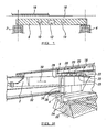
- FIG. 1 there is illustrated the top part of a load bearing construction in the form of a bridge formed in accordance with the invention.
- the bridge includes first and second bridge supports 2,4 the top ends of which are shown and the supports are spanned by a deck structure 8 formed in accordance with the invention as will be explained in more detail later.
- the deck structure includes a series of passages 10,12,14 which connect a shielded area (not shown) at the leading edge of the deck structure in which excavation works take place, to the surrounding environment.
- the passages allow the return of excavated materials to be discarded, access for persons and the passages of utilities.
- the deck structure in this embodiment is to be installed under existing facilities, in this case a rail track.
- the structure supports an upper surface 16 of the bridge which includes ballast, sub ballast and, in this case as the bridge which is formed is to support an existing track, a rail track 18 support system.
- FIG. 2 illustrates a perspective view of another bridge structure formed in accordance with the invention and the same reference numerals are used for the same features for ease of reference.
- a rail track is supported by the deck structure 8 formed from a series of precast beam units 20 supported between the bridge supports 2,4.
- the decking structure can be formed from a large precast slab construction which typically would be constructed on a launch pad adjacent to the bridge.
- a guide and bearing track 34 is constructed very precisely which will be the path along which the jacked deck will slide.
- the upper part of the supports are designed so that a section or lid can be removed to expose this track 34.
- a launch area is provided and in this case a series of precast beams 20 are provided which are jacked in successively as indicated by the arrow 30 to form the decking structure which spans the bridge supports 2,4.
- a steel shield (not shown) is formed at the leading edge of the decking structure where excavation is required to take place to form the cavities into which the decking structure is to be advanced. Access to the shield for workers and for soil removal, air and power supply is provided by a series of passages 10, 12, 14 in the decking structure as already described.
- known techniques can be used to provide friction reduction and avoid lateral movement of the facility. If the decking structure is provided relatively close to the top of the upper surface 16, conventional techniques can be used to transfer the upper surface load directly on to the deck structure as it is jacked forward.
- the present invention therefore provides significant advantages in comparison to conventional techniques.
- the conventional approach would have been to cast at site a large underpass box of the length required. This is difficult and has large costs involved in providing a suitable launch area for the box.
- no box is required as the decking structure is formed from the relatively slim, precast beams or a single, thin slab unit and hence the launch area and formation work required is significantly reduced.
- FIG 3 there is shown a method of constructing the foundations and wall for the deck structure 100.
- access box is 102, 104 are driven into position at each side of the structure.
- These boxes fulfil three functions in the following sequence. Firstly, the internal vertical wall 106 of each box provides part of the walls of the structure. Secondly, after having driven the boxes to a predetermined height suitable for the installation of the deck structure 100 as shown, the boxes provide access for a piling or diaphragm wall system from which the walls of the structure could be constructed. Thirdly, after the above work is completed, a bearing and track can be prepared in the internal upper part of the boxes to provide a slide path 108 as the deck structure 100 is installed by jacking.
- the space 110 below the track can be filled with concrete to provide a permanent founding and wall structure.
- the access box 102, 104 can be designed so that during jacking it will be possible to remove the upper corner right and left hand lids 112 respectively to expose the track slide paths 108.
- FIG 4 is an isometric view which illustrates the concept of jacking a deck structure 200 in the form of a series of beam units onto two previously installed supports 202, 204. It is possible to jack the deck structure immediately below the rail tracks 206 and the load of the track and trains is transferred directly onto the top of the structure and not through any soil cover. This is done by constructing a load spreading support grid (not shown) immediately below the track. This consists of structural sections constructed parallel to the track and cross connections across the width of the tracks. The longitudinal members parallel to the sleepers and at the same level, the cross members below the longitudinal members. All of these parts can be installed in short possessions and with care taken to ensure the level is correct as the deck will be jacked to interface with this support system.
- the shield 208 at the leading edge of the deck structure is shown and, in this embodiment, as the deck advances, projecting "spiles" from the shield can be designed to make contact with the cross members of the support grid and pick up the track load in advance of the deck. This ensures that effective load transfer takes place.
- two methods can be used, these being either the use of industrial "skates" between the top of the box and the cross beams or the use of Teflon faces on the deck and cross beams with suitable lubricants.
- FIG 5 there is shown the leading edge 302 of a deck structure 300 positioned to be introduced and moved along supports 302, 304 which are provided with tracks 306.
- the deck structure is formed from a series of beam units 308 which are advanced into the space 310 in direction 312 until in the desired position.
- the leading edge 302 has a shield 314 attached thereto and the shield allows protection for personnel in the area 316 who are excavating the space 312 in advance of the deck structure. If required side shields 318 can be provided to protect the tracks 306.
- the use of a deck structure in accordance with the invention requires much less excavation and reduces face stability and settlement problems.
- the typical volume of excavation in the tunnelling operation for the bridge supports and decking structure is 1/3 rd of that of a conventional full equivalent box.
- the majority of the bulk excavation (2/3rds) and its removal can be undertaken with standard equipment economically and quickly.
- the face area exposed at any time is very limited this reduces greatly the risk of soil loss and settlement and avoids the large face stability and settlement issues that are found in excavating the full face of a conventional box as typically no face of the new decking structure is higher than 2m This is a major advantage in difficult ground when compared to a typical jacked box height of 7- 8m.
- the size of the exposed face using the modular bridge support units and decking structure is very limited and this reduces the risk of collapse. Because units are precast the time on site can be greatly reduced and as the work can be performed from relatively small jacking pits for the bridge supports the decking structure can be prepared at a relatively high level so will require relatively little excavation for the launch area. The main bulk of excavation for the underpass can be done freely with conventional earth moving machinery (not in tunnelling) after the structure is in place supporting the existing facility.
- the current invention also ensures that the line and level of the decking structure are controlled accurately.
- Time savings can also be achieved as the bridge supports can be installed simultaneously so reducing the period of construction and the decking structure can be installed more rapidly than a box as the jacking forces required are much reduced which in turn reduces the reaction requirements that have to be installed.
- This invention therefore allows the whole of the underground structure, foundations, walls and deck/roof to be installed without surface disruption.
- the depth of a deck or a beam to span 10 metres or more will have a depth of 1.5 metres and upwards. This provides sufficient depth to install a temporary shield on the leading edge of the deck and for access to be provided for persons to manually excavate.
- Virtually any form of underground structure can be created by using differing configurations of modular units and jacked decks
Description
- The invention to which this application relates is the provision of a deck structure for use as part of a load bearing construction such as a bridge and also a method for the installation of the same.
- The provision of deck structures is now described with reference to a bridge although it should be appreciated that the same apparatus and method may be used to effect with respect to other load bearing structures such as underpasses, underground stations roofs or the like and therefore the description relating to use for bridges should be interpreted in a non-limiting manner.
- There is an increasing demand to be able to provide new facilities and structures without affecting existing surface facilities such as rail tracks, roads or the like. Until recently the construction of a bridge would have required construction to be done from the surface using conventional construction techniques and involving considerable disruption and risk to the surface facility, and/or it may be necessary to make expensive temporary diversions of the surface facility to allow the structure to be constructed.
- Alternatively the bridge can be constructed more or less complete at a separate location and then slid in to position at a relatively quiet period of use of the existing road or rail services. However, this requires installation in advance of foundations in the form of slide paths, the closure of the rail or road, complete removal of materials and subsequent reinstatement.
- Other techniques for forming a deck to allow a new facility to be formed underneath include the jacking of a concrete box structure into position. However these box structures tend to be very large and so a large site is required to allow the structures to be formed adjacent to the bridge which can be expensive. Furthermore the size of these box structures means that large scale excavation needs to be performed to allow the cavities of a required size to be formed to receive the box structures and the jacking forces needed to move large boxes are very great.
- It is also known to create advance support structures so as to form a canopy of tubes which act as a partial support structure but these are not capable of supporting the facility loads without provision of internal support arches as excavation is undertaken inside the canopy.
-
EP0431909 discloses a method of forming a structure in which there is provided a roof or superstructure which is moved into position first, either by excavation in front of the advancement of the superstructure or by lowering the same into an excavated area. The soil under the superstructure is used to support the same in position until a substructure including a base and support walls is then advanced after the superstructure into position by excavating the soil under the superstructure such that as the same progresses the support walls serve to support the superstructure rather than the soil. - However none of the prior art methods and apparatus allow the decking structure to be formed in an efficient manner.
- The aim of the present invention is to provide a method for the provision of a load bearing construction including a deck structure, while minimising disruption to a facility which passes over the Construction while the same is being formed.
- In a first aspect of the invention there is provided a method for the formation of a load bearing construction without disruption of the surface above the load bearing construction during formation, said load bearing construction including a deck structure located on and supported by at least first and second supports, said method including the steps of forming at least part of the deck structure from one or a series of slab or beam units, forming the at least first and second spaced supports, each support formed to a height which is required to receive the deck structure thereon, advancing the deck structure into a space defined above the supports and excavating as required at the leading edge of the deck structure to form the said space, advancing the deck structure into the space formed until the deck structure is in the required position on the supports and characterised in that the said supports are formed at the location at which the said construction is to be formed, prior to advancement of the one or a series of slab or beam units along tracks formed in the supports and along which the slab or beam units slide in a guided manner into position to form the deck structure and supporting the deck structure on the supports along which the same has been slid to form the load bearing construction.
- Typically the slabs or beam units are formed from concrete.
- In one embodiment said leading edge of said deck structure includes a shielded area within which excavation works can be performed to form a space into which the structure can be advanced, said shielded area in communication with externally of the construction via one or more passages formed in the deck structure. The shield is preferably compartmentalised to assist in controlling the face excavation.
- In one embodiment a metal shield is provided.
- In one embodiment the deck structure slabs or beams are constructed with access voids to allow passage to and from the leading face of the deck structure for men, spoil removal, services or the like and it is preferably possible as work proceeds to excavate underneath the deck structure soffit during the installation where additional access is needed.
- In one embodiment the supports are in the form of a series of units which act as abutments and piers. Typically, the supports are formed prior to advancement of the deck structure into position, said supports formed to an appropriate height to receive the deck structure. In one embodiment the supports are formed by the jacking of foundation boxes, followed by the jacking of wall units along the foundation units to a height appropriate for the receipt of the underside of the deck structure.
- In one embodiment the deck structure includes one slab unit formed to the appropriate dimensions prior to jacking into position. In an alternative embodiment a series of slabs or beams are used in combination, said slabs or beams successively advanced into position.
- In one embodiment the depth of the slabs or beams depend on the size of the span between the bridge supports but may be no less than 1.5 metres and is preferably in the range of 2 metres.
- The width of the deck structure is dependent upon the particular use of the construction, for example, the width of the structure for a road bridge will be greater than the width of the structure for a single track rail bridge.
- In one embodiment there is provided a fixed and sliding bearing between the deck structure and supports to allow the slab to take up the lateral movements arising from thermal or other causes. Suitable bearings are constructed in the top of the upper wall units of the supports prior to installing the deck. These bearings in one embodiment are revealed by removal of cover plates on the top of the wall unit from inside the shield as the deck structure is jacked into position.
- Preferably the method includes the initial steps of forming the bridge supports by jacking into position foundation units and jacking into place thereon wall units to a height required to receive the deck structure thereon.
- In one embodiment the method involves the step of moving a deck structure formed from a single precast concrete slab. In an alternative embodiment the deck structure is formed from a series of beams or slabs which are successively advanced as the decking structure is moved forward.
- The method involves, in one embodiment, the step of forming, at the leading edge of the deck structure, a shielded area, said shielded area allowing excavation works to be performed to ensure that the required space is formed to allow the deck structure to be advanced into the space formed by the excavation works.
- In one embodiment, the deck structure is advanced into position in a space and when in position the upper surface will be required to be load bearing, i.e. to support facilities such as roads or rail over which traffic or trains pass. During the installation procedure, if the facility is already present above the space, temporary load bearing structures are used to support the upper surface until the deck structure has been advanced into position.
- Typically, all of the decking structure is load bearing and is capable of carrying dead weight (of soil) and live (Traffic) loads. Temporary supports can be provided for the track to allow the live loads to be carried and distributed.
- Typically once the deck structure is in position, any further excavation works and/or the formation of a road surface or rail track can be undertaken.
- In one embodiment the slabs or beam units which make up the decking structure include one or more channels formed therethrough to allow any of access for persons, equipment and/or removal of excavated material from the shielded area.
- In one embodiment as the deck is jacked forward, lids on the top faces of the supports are removed to expose a slide track or channel along which the beams can be slid in a guided manner into position. These areas can also act as a permanent bearing.
- In one embodiment the friction between the soil and the top of the deck can be reduced to low values by the use of tried and tested methods of drag sheets or drag ropes. Typically the jacking loads at all stages of installation are relatively small as the individual size of a plurality of jacked structure units offers only a small frictional surface
- In one embodiment said deck or roof is moved into position by horizontally jacking one or more slab or beam units which are cast in-situ or individually.
- In one embodiment the invention is of particular use in relatively shallow applications such as road underpasses where it is important not to disrupt surface traffic or surface structures. In relatively deep underground constructions the invention is also of advantage as, because of the depth, it is more economic to install the structure using horizontal jacking methods to create the structure envelope ahead of the excavation of the earth.
- Specific embodiments of the invention are now described with reference to the accompanying drawings; wherein
-
Figure 1 illustrates an elevation of part of a load bearing construction formed in accordance with the invention in one embodiment; -
Figure 2 illustrates a perspective view of part of a further load bearing construction formed in accordance with the invention; -
Figure 3 illustrates an elevation of another form of supports and foundations which can be used to provide the supports for the deck structure in accordance with the invention; -
Figure 4 illustrates a further embodiment of the invention; and -
Figure 5 illustrates a detailed view of a shield arrangement for the jacked deck structure. - Referring firstly to
Figure 1 there is illustrated the top part of a load bearing construction in the form of a bridge formed in accordance with the invention. The bridge includes first and second bridge supports 2,4 the top ends of which are shown and the supports are spanned by adeck structure 8 formed in accordance with the invention as will be explained in more detail later. The deck structure includes a series ofpassages - The deck structure in this embodiment is to be installed under existing facilities, in this case a rail track. The structure supports an
upper surface 16 of the bridge which includes ballast, sub ballast and, in this case as the bridge which is formed is to support an existing track, arail track 18 support system. -
Figure 2 illustrates a perspective view of another bridge structure formed in accordance with the invention and the same reference numerals are used for the same features for ease of reference. In this case a rail track is supported by thedeck structure 8 formed from a series ofprecast beam units 20 supported between the bridge supports 2,4. - Although shown and herein described with the formation of the decking structure utilising a series of precast beams the decking structure can be formed from a large precast slab construction which typically would be constructed on a launch pad adjacent to the bridge.
- An example of the method used to allow the formation of the bridge and decking structure is now provided with respect to the embodiment where the decking structure is formed from a series of precast beams and with reference to
Figure 2 . The sequence for construction can be as follows: - 1. Excavate launch pits at each of the three points sufficiently wide to set foundation boxes for the supports and provide reaction arrangements.
- 2. Using precast boxes with the leading one fitted with a cutting shield, commence the jacking installation excavating in the shield and add additional precast boxes as they are jacked through the pit
- 3. Once the foundation units are installed wall units are jacked on top of the boxes. These units ride in channels formed in the top of the foundation boxes. They are fitted with a cutting shield where excavation is undertaken.
- 4. If required a second wall unit can be placed on top of the first.
- 5. As the upper parts of the structures are jacked in falsework is installed in the pits to allow jacking at higher levels.
- 6. If required all three structures can be installed at the same time
- In this way the basic shell of the bridge supports is created. These units provide access for undertaking additional operations like stabilising or reinforcing soil below the boxes.
- Once the support units are in position it is then possible to undertake the operations necessary to turn them into a homogenous structure. This can be done by filling the units with concrete and stressing them together. In order to receive the jacked deck structure, in the upper section of the wall boxes a guide and bearing
track 34 is constructed very precisely which will be the path along which the jacked deck will slide. The upper part of the supports are designed so that a section or lid can be removed to expose thistrack 34. - A launch area is provided and in this case a series of
precast beams 20 are provided which are jacked in successively as indicated by thearrow 30 to form the decking structure which spans the bridge supports 2,4. - A steel shield (not shown) is formed at the leading edge of the decking structure where excavation is required to take place to form the cavities into which the decking structure is to be advanced. Access to the shield for workers and for soil removal, air and power supply is provided by a series of
passages - As required, known techniques can be used to provide friction reduction and avoid lateral movement of the facility. If the decking structure is provided relatively close to the top of the
upper surface 16, conventional techniques can be used to transfer the upper surface load directly on to the deck structure as it is jacked forward. - Once the deck structure is in place as shown on the bridge supports 2, 4 in
figure 2 then the removal of any further soil and any special measures needed can be undertaken without difficulty as the facility is fully supported. All other works such as installation of roadways, track formation, surface finishes can also be undertaken. - The present invention therefore provides significant advantages in comparison to conventional techniques. For example, in the embodiment shown in
Figure 2 where anew road 32 is to be located under the bridge which has caused the need for the bridge, the conventional approach would have been to cast at site a large underpass box of the length required. This is difficult and has large costs involved in providing a suitable launch area for the box. In the current invention no box is required as the decking structure is formed from the relatively slim, precast beams or a single, thin slab unit and hence the launch area and formation work required is significantly reduced. - The foundations and walls onto which the deck structure in accordance with the invention is moved and subsequently supported by can be installed in a number of ways, one of which has been described with reference to
Figure 2 and another useful method is now described with reference toFigure 3 . - In
Figure 3 there is shown a method of constructing the foundations and wall for thedeck structure 100. In this case, to install the foundation and walls for use as an underpass structure, access box is 102, 104 are driven into position at each side of the structure. These boxes fulfil three functions in the following sequence. Firstly, the internalvertical wall 106 of each box provides part of the walls of the structure. Secondly, after having driven the boxes to a predetermined height suitable for the installation of thedeck structure 100 as shown, the boxes provide access for a piling or diaphragm wall system from which the walls of the structure could be constructed. Thirdly, after the above work is completed, a bearing and track can be prepared in the internal upper part of the boxes to provide aslide path 108 as thedeck structure 100 is installed by jacking. After preparation of thetrack 108 thespace 110 below the track can be filled with concrete to provide a permanent founding and wall structure. Theaccess box left hand lids 112 respectively to expose thetrack slide paths 108. -
Figure 4 is an isometric view which illustrates the concept of jacking adeck structure 200 in the form of a series of beam units onto two previously installedsupports rail tracks 206 and the load of the track and trains is transferred directly onto the top of the structure and not through any soil cover. This is done by constructing a load spreading support grid (not shown) immediately below the track. This consists of structural sections constructed parallel to the track and cross connections across the width of the tracks. The longitudinal members parallel to the sleepers and at the same level, the cross members below the longitudinal members. All of these parts can be installed in short possessions and with care taken to ensure the level is correct as the deck will be jacked to interface with this support system. Infigure 4 theshield 208 at the leading edge of the deck structure is shown and, in this embodiment, as the deck advances, projecting "spiles" from the shield can be designed to make contact with the cross members of the support grid and pick up the track load in advance of the deck. This ensures that effective load transfer takes place. In order to ensure that no horizontal force is induced in the support system two methods can be used, these being either the use of industrial "skates" between the top of the box and the cross beams or the use of Teflon faces on the deck and cross beams with suitable lubricants. Once the deck structure is installed the rail tracks are completely carried directly by the deck. - In
figure 5 there is shown theleading edge 302 of adeck structure 300 positioned to be introduced and moved alongsupports tracks 306. The deck structure is formed from a series ofbeam units 308 which are advanced into thespace 310 indirection 312 until in the desired position. Theleading edge 302 has ashield 314 attached thereto and the shield allows protection for personnel in thearea 316 who are excavating thespace 312 in advance of the deck structure. If required side shields 318 can be provided to protect thetracks 306. - The use of a deck structure in accordance with the invention requires much less excavation and reduces face stability and settlement problems. The typical volume of excavation in the tunnelling operation for the bridge supports and decking structure is 1/3rd of that of a conventional full equivalent box. Furthermore, the majority of the bulk excavation (2/3rds) and its removal can be undertaken with standard equipment economically and quickly. Furthermore as the face area exposed at any time is very limited this reduces greatly the risk of soil loss and settlement and avoids the large face stability and settlement issues that are found in excavating the full face of a conventional box as typically no face of the new decking structure is higher than 2m This is a major advantage in difficult ground when compared to a typical jacked box height of 7- 8m. As a result, the size of the exposed face using the modular bridge support units and decking structure is very limited and this reduces the risk of collapse. Because units are precast the time on site can be greatly reduced and as the work can be performed from relatively small jacking pits for the bridge supports the decking structure can be prepared at a relatively high level so will require relatively little excavation for the launch area. The main bulk of excavation for the underpass can be done freely with conventional earth moving machinery (not in tunnelling) after the structure is in place supporting the existing facility.
- The current invention also ensures that the line and level of the decking structure are controlled accurately.
- Time savings can also be achieved as the bridge supports can be installed simultaneously so reducing the period of construction and the decking structure can be installed more rapidly than a box as the jacking forces required are much reduced which in turn reduces the reaction requirements that have to be installed.
- This invention therefore allows the whole of the underground structure, foundations, walls and deck/roof to be installed without surface disruption. Typically the depth of a deck or a beam to span 10 metres or more will have a depth of 1.5 metres and upwards. This provides sufficient depth to install a temporary shield on the leading edge of the deck and for access to be provided for persons to manually excavate. Virtually any form of underground structure can be created by using differing configurations of modular units and jacked decks
- These can range from underpasses with spans of 10m upwards and by use of more than one span and a central pier it is possible to create separate carriageways.
- For large underground structures at depth, such as metro stations it is possible from relatively small access excavations to create a structural shell which allows the majority of the work to be undertaken inside it safely and without surface disruption. The spans are limited only by the practicalities of the deck design and can easily exceed 20metres.
- All of these features individually or in combination ensure that there is provided an installation method which provides a less disruptive method requiring no possessions or shut downs of any existing facilities such as road or rail tracks passing over the construction.
Claims (13)
- A method for the formation of a load bearing construction without disruption of the surface above the load bearing construction during formation, said load bearing construction including a deck structure (8; 100; 200; 300) located on and supported by at least first and second supports (2,4; 102, 104; 202,204; 302;304), said method including the steps of forming at least part of the deck structure (8; 100; 200;300) from one or a series of slab or beam units (20; 308), forming the at least first and second spaced supports (2,4; 102, 104; 202;204; 302;304), each support formed to a height which is required to receive the deck structure thereon, advancing the deck structure (8; 100;200;300) into a space (310) defined above the supports (2,4;102;104,202,204;302,304) and excavating as required at the leading edge (302) of the deck structure (8;100;200;300) to form the said space, advancing the deck structure (8;100;200;300) into the space formed until the deck structure is in the required position on the supports (2,4; 102,104;202,204;302,304) and characterised in that the said supports (2,4; 102,104;202,204;302,304) are formed at the location at which the said construction is to be formed, prior to advancement of the one or a series of slab or beam units along tracks (34, 108) formed in the supports and along which the slab or beam units slide in a guided manner into position to form the deck structure (8; 100;200;300) and supporting the deck structure (8; 100;200;300) on the supports (2,4; 102,104;202,204;302,304) along which the same has been slid to form the load bearing construction.
- A method according to claim 1 characterised in that the supports are formed by jacking into position foundation un its and jacking into place thereon wall units to a height required to receive the deck structure thereon and along which the deck support slides.
- A method according to claim 1 characterised in that the method involves the step of moving a deck structure formed from a single precast slab.
- A method according to claim 1 characterised in that the method involves the step of forming the deck structure from a series of beam or slab units which are successively introduced as the deck structure is moved forward.
- A method according to claim 1 characterised in that the method involves the step of locating at the leading edge of the deck structure, a shield, said shield allowing excavation works to be performed safely to form the space into which the deck structure is to be advanced.
- A method according to claim 1 characterised in that the space into which the deck structure is advanced has a top face which is load bearing until the deck structure has been moved into the space.
- A method according to claim 6 characterised in that the deck structure is introduced into a space formed under an existing road or rail facility.
- A method according to claim 7 characterised in that once the deck structure is in position, the load of the road or rail track is taken by the deck structure.
- A method according to claim 1 characterised in that the deck structure includes one or more channels formed therethrough to allow access for persons, equipment and/or removal of excavated material.
- A method according to claim 9 characterised in that the slide tracks act as a permanent bearing for the deck structure.
- A method according to claim 9 characterised in that the slide track is constructed at the top of the supports prior to installing the deck structure.
- A method according to claim 11 characterised in that the slide track bearings are revealed by the removal of lids on the supports as the deck structure moves forward.
- A method according to claim 12 characterised in that the bearings are successively exposed as the deck structure is advanced into position.
Priority Applications (1)
| Application Number | Priority Date | Filing Date | Title |
|---|---|---|---|
| PL06253588T PL1743978T3 (en) | 2005-07-09 | 2006-07-07 | Method for the formation of a load bearing construction |
Applications Claiming Priority (1)
| Application Number | Priority Date | Filing Date | Title |
|---|---|---|---|
| GBGB0514142.9A GB0514142D0 (en) | 2005-07-09 | 2005-07-09 | Bridge decking and method for installation |
Publications (3)
| Publication Number | Publication Date |
|---|---|
| EP1743978A2 EP1743978A2 (en) | 2007-01-17 |
| EP1743978A3 EP1743978A3 (en) | 2009-08-05 |
| EP1743978B1 true EP1743978B1 (en) | 2013-09-25 |
Family
ID=34897006
Family Applications (1)
| Application Number | Title | Priority Date | Filing Date |
|---|---|---|---|
| EP06253588.5A Active EP1743978B1 (en) | 2005-07-09 | 2006-07-07 | Method for the formation of a load bearing construction |
Country Status (5)
| Country | Link |
|---|---|
| US (1) | US8347441B2 (en) |
| EP (1) | EP1743978B1 (en) |
| DK (1) | DK1743978T3 (en) |
| GB (1) | GB0514142D0 (en) |
| PL (1) | PL1743978T3 (en) |
Families Citing this family (3)
| Publication number | Priority date | Publication date | Assignee | Title |
|---|---|---|---|---|
| CN103031803B (en) * | 2013-01-17 | 2014-11-26 | 铁道第三勘察设计院集团有限公司 | Small-intersection angle low-height reinforced concrete overpass bridge structure |
| CN108005110A (en) * | 2016-10-28 | 2018-05-08 | 广州地铁设计研究院有限公司 | The overlay structure and its construction method of a kind of Urban Bridge and interior space of metro station |
| CN112709256B (en) * | 2020-12-24 | 2022-12-02 | 中建四局第六建设有限公司 | Underground chamber roof post-cast strip non-roof-return structure and construction method |
Family Cites Families (18)
| Publication number | Priority date | Publication date | Assignee | Title |
|---|---|---|---|---|
| US3125009A (en) * | 1964-03-17 | Figure | ||
| US2184137A (en) * | 1936-12-01 | 1939-12-19 | Nat Fireproofing Corp | Composite building member |
| DE1902890A1 (en) * | 1969-01-22 | 1970-08-27 | Polensky & Zoellner Bauunterne | Device for moving bridges |
| DE2219567A1 (en) * | 1972-04-21 | 1973-10-31 | Held & Francke Bau Ag | PROCEDURE FOR NIGHTLY INSTALLATION OF AN UNDERGROUND STRUCTURE |
| FR2244868B3 (en) * | 1973-09-24 | 1976-08-20 | Gecti | |
| FR2546202B1 (en) * | 1983-05-16 | 1986-03-21 | Bouygues Sa | BRIDGE WITH PREFABICATED CUSHIONS AND EXTERIOR CABLE PRESSURE, CUSHIONS FOR THIS BRIDGE AND METHODS OF MANUFACTURE THEREOF |
| US4918777A (en) * | 1987-12-07 | 1990-04-24 | Ashley Eddie L | Slab-stem unit forming a trafficway |
| CA1311094C (en) * | 1989-07-12 | 1992-12-08 | Gamil S. Tadros | Bridge construction |
| GB8927648D0 (en) * | 1989-12-07 | 1990-02-07 | Aeb Jacked Structures Ltd | Improvements in and relating to forming a passageway through the ground |
| US5511266A (en) * | 1994-12-06 | 1996-04-30 | Bridgesys Corporation | Continuous incrementally erecting viaduct construction system |
| US5940916A (en) * | 1997-09-03 | 1999-08-24 | J. Muller International | Bridge span-by-span construction apparatus and method |
| JPH11336021A (en) * | 1998-05-25 | 1999-12-07 | Kazaoka Kazumi | Bridge floor slab unit and execution of bridge floor slab using the unit |
| US6170105B1 (en) * | 1999-04-29 | 2001-01-09 | Composite Deck Solutions, Llc | Composite deck system and method of construction |
| CA2365143A1 (en) * | 2000-12-09 | 2002-06-09 | West Virginia University | Lightweight fiber reinforced polymer composite modular panel |
| US6795992B2 (en) * | 2002-10-03 | 2004-09-28 | Paul H. Markelz | Bridge construction method |
| JP3708517B2 (en) * | 2002-12-03 | 2005-10-19 | 朝日エンヂニヤリング株式会社 | Floor structure |
| KR100604251B1 (en) * | 2004-09-06 | 2006-07-28 | 주식회사 국민씨아이 | Fiber Reinforced Composite Bridge Deck of Tubular Profile?Having Snap-fit Connection |
| US7546656B2 (en) * | 2005-08-16 | 2009-06-16 | Daewoo Engineering & Construction Co., Ltd | Method of installing prefabricated, segment concrete filled tube members |
-
2005
- 2005-07-09 GB GBGB0514142.9A patent/GB0514142D0/en not_active Ceased
-
2006
- 2006-07-07 PL PL06253588T patent/PL1743978T3/en unknown
- 2006-07-07 US US11/482,224 patent/US8347441B2/en active Active
- 2006-07-07 EP EP06253588.5A patent/EP1743978B1/en active Active
- 2006-07-07 DK DK06253588.5T patent/DK1743978T3/en active
Also Published As
| Publication number | Publication date |
|---|---|
| US8347441B2 (en) | 2013-01-08 |
| EP1743978A2 (en) | 2007-01-17 |
| EP1743978A3 (en) | 2009-08-05 |
| DK1743978T3 (en) | 2013-12-16 |
| PL1743978T3 (en) | 2014-03-31 |
| US20070006401A1 (en) | 2007-01-11 |
| GB0514142D0 (en) | 2005-08-17 |
Similar Documents
| Publication | Publication Date | Title |
|---|---|---|
| US9322137B2 (en) | Method for building structures, particularly passages under operating railways or the like | |
| CN113482044B (en) | Power pipeline relocation method for invading subway station structure | |
| EP1743978B1 (en) | Method for the formation of a load bearing construction | |
| US20130243528A1 (en) | Formation of Underground Constructions | |
| CN114908805A (en) | Strip drawing construction method for open cut tunnel with subway striding upwards | |
| EP1021640B1 (en) | Arched support structure | |
| RU2715497C1 (en) | Method of erection and arrangement of a single-span underground metro station of an open method of performing works | |
| CN103967052A (en) | Method for protecting height difference soil bodies of bases of new frame structure bridge and old frame structure bridge | |
| US10435854B2 (en) | Construction methods and systems for grade separation structures | |
| EP0431909B1 (en) | Improvements in and relating to forming a passageway through the ground | |
| EP1820934A1 (en) | Method and system for forming a tunnel beneath a travelway | |
| Clarkson et al. | PIPE-JACKING APPLIED TO LARGE STRUCTURES. | |
| Konstantis et al. | Box jacking/pushing method for tunnel construction in rock: Doha Metro, Gold Line Project | |
| Thomson et al. | Jacked installation of underbridges | |
| SU1481417A1 (en) | Method of constructing a tunnel under railway | |
| Taylor et al. | Developments in Tunnel Jacking | |
| Sdoga et al. | Design and construction of artificial tunnels in urban context | |
| Glass et al. | Construction of Westminster Station, London | |
| Lippard | CANNON STREET STATION AIR RIGHTS DEVELOPMENT. | |
| Anderson et al. | DESIGN AND CONSTRUCTION OF THE KINGSFERRY LIFTING BRIDGE, ISLE OF SHEPPEY. | |
| Beavor et al. | Design and construction of two launched bridges | |
| Field et al. | Design and construction of London Bridge station on the Jubilee Line Extension | |
| Humphries | 5-Gautrain Project South Africa: Southern Viaduct Section Substructure design and construction: construction and project management | |
| Ho et al. | I-Girders Method Used to Support Existing Railway Operations During Highway Underpass Construction | |
| Allard et al. | JUBILEE LINE EXTENSION: WATERLOO STATION TICKET HALL CONSTRUCTION. |
Legal Events
| Date | Code | Title | Description |
|---|---|---|---|
| PUAI | Public reference made under article 153(3) epc to a published international application that has entered the european phase |
Free format text: ORIGINAL CODE: 0009012 |
|
| AK | Designated contracting states |
Kind code of ref document: A2 Designated state(s): AT BE BG CH CY CZ DE DK EE ES FI FR GB GR HU IE IS IT LI LT LU LV MC NL PL PT RO SE SI SK TR |
|
| AX | Request for extension of the european patent |
Extension state: AL BA HR MK YU |
|
| PUAL | Search report despatched |
Free format text: ORIGINAL CODE: 0009013 |
|
| AK | Designated contracting states |
Kind code of ref document: A3 Designated state(s): AT BE BG CH CY CZ DE DK EE ES FI FR GB GR HU IE IS IT LI LT LU LV MC NL PL PT RO SE SI SK TR |
|
| AX | Request for extension of the european patent |
Extension state: AL BA HR MK RS |
|
| 17P | Request for examination filed |
Effective date: 20090825 |
|
| 17Q | First examination report despatched |
Effective date: 20091015 |
|
| AKX | Designation fees paid |
Designated state(s): AT BE BG CH CY CZ DE DK EE ES FI FR GB GR HU IE IS IT LI LT LU LV MC NL PL PT RO SE SI SK TR |
|
| 111L | Licence recorded |
Designated state(s): AT BE BG CH CY CZ DE DK EE ES FI FR GB GR HU IE IS IT LT LU LV MC NL PL PT RO SE SI SK TR Name of requester: VOLKER FITZPATRICK LIMITED AND HOCHTIEF (UK) CONST Effective date: 20110209 |
|
| RIC1 | Information provided on ipc code assigned before grant |
Ipc: E02D 29/045 20060101ALI20130315BHEP Ipc: E01D 21/06 20060101AFI20130315BHEP Ipc: E21D 9/00 20060101ALI20130315BHEP |
|
| GRAP | Despatch of communication of intention to grant a patent |
Free format text: ORIGINAL CODE: EPIDOSNIGR1 |
|
| INTG | Intention to grant announced |
Effective date: 20130503 |
|
| GRAS | Grant fee paid |
Free format text: ORIGINAL CODE: EPIDOSNIGR3 |
|
| GRAP | Despatch of communication of intention to grant a patent |
Free format text: ORIGINAL CODE: EPIDOSNIGR1 |
|
| GRAA | (expected) grant |
Free format text: ORIGINAL CODE: 0009210 |
|
| INTG | Intention to grant announced |
Effective date: 20130808 |
|
| 111L | Licence recorded |
Designated state(s): AT BE BG CH CY CZ DE DK EE ES FI FR GB GR HU IE IS IT LT LU LV MC NL PL PT RO SE SI SK TR Name of requester: VOLKER FITZPATRICK LIMITED AND HOCHTIEF (UK) CONST Effective date: 20110209 |
|
| AK | Designated contracting states |
Kind code of ref document: B1 Designated state(s): AT BE BG CH CY CZ DE DK EE ES FI FR GB GR HU IE IS IT LI LT LU LV MC NL PL PT RO SE SI SK TR |
|
| REG | Reference to a national code |
Ref country code: GB Ref legal event code: FG4D |
|
| REG | Reference to a national code |
Ref country code: CH Ref legal event code: PK Free format text: ERGAENZUNG LIZENZEINTRAG: NICHT AUSSCHLIESSLICHE LIZENZ Ref country code: CH Ref legal event code: EP |
|
| REG | Reference to a national code |
Ref country code: AT Ref legal event code: REF Ref document number: 633760 Country of ref document: AT Kind code of ref document: T Effective date: 20131015 |
|
| REG | Reference to a national code |
Ref country code: IE Ref legal event code: FG4D |
|
| REG | Reference to a national code |
Ref country code: DE Ref legal event code: R096 Ref document number: 602006038554 Country of ref document: DE Effective date: 20131114 |
|
| REG | Reference to a national code |
Ref country code: DK Ref legal event code: T3 Effective date: 20131213 |
|
| REG | Reference to a national code |
Ref country code: CH Ref legal event code: NV Representative=s name: ABREMA AGENCE BREVET ET MARQUES, GANGUILLET, CH |
|
| REG | Reference to a national code |
Ref country code: NL Ref legal event code: T3 |
|
| PG25 | Lapsed in a contracting state [announced via postgrant information from national office to epo] |
Ref country code: SE Free format text: LAPSE BECAUSE OF FAILURE TO SUBMIT A TRANSLATION OF THE DESCRIPTION OR TO PAY THE FEE WITHIN THE PRESCRIBED TIME-LIMIT Effective date: 20130925 Ref country code: LT Free format text: LAPSE BECAUSE OF FAILURE TO SUBMIT A TRANSLATION OF THE DESCRIPTION OR TO PAY THE FEE WITHIN THE PRESCRIBED TIME-LIMIT Effective date: 20130925 |
|
| REG | Reference to a national code |
Ref country code: AT Ref legal event code: MK05 Ref document number: 633760 Country of ref document: AT Kind code of ref document: T Effective date: 20130925 |
|
| REG | Reference to a national code |
Ref country code: LT Ref legal event code: MG4D |
|
| PG25 | Lapsed in a contracting state [announced via postgrant information from national office to epo] |
Ref country code: GR Free format text: LAPSE BECAUSE OF FAILURE TO SUBMIT A TRANSLATION OF THE DESCRIPTION OR TO PAY THE FEE WITHIN THE PRESCRIBED TIME-LIMIT Effective date: 20131226 Ref country code: LV Free format text: LAPSE BECAUSE OF FAILURE TO SUBMIT A TRANSLATION OF THE DESCRIPTION OR TO PAY THE FEE WITHIN THE PRESCRIBED TIME-LIMIT Effective date: 20130925 Ref country code: SI Free format text: LAPSE BECAUSE OF FAILURE TO SUBMIT A TRANSLATION OF THE DESCRIPTION OR TO PAY THE FEE WITHIN THE PRESCRIBED TIME-LIMIT Effective date: 20130925 Ref country code: FI Free format text: LAPSE BECAUSE OF FAILURE TO SUBMIT A TRANSLATION OF THE DESCRIPTION OR TO PAY THE FEE WITHIN THE PRESCRIBED TIME-LIMIT Effective date: 20130925 |
|
| PG25 | Lapsed in a contracting state [announced via postgrant information from national office to epo] |
Ref country code: BE Free format text: LAPSE BECAUSE OF FAILURE TO SUBMIT A TRANSLATION OF THE DESCRIPTION OR TO PAY THE FEE WITHIN THE PRESCRIBED TIME-LIMIT Effective date: 20130925 |
|
| PG25 | Lapsed in a contracting state [announced via postgrant information from national office to epo] |
Ref country code: RO Free format text: LAPSE BECAUSE OF FAILURE TO SUBMIT A TRANSLATION OF THE DESCRIPTION OR TO PAY THE FEE WITHIN THE PRESCRIBED TIME-LIMIT Effective date: 20130925 Ref country code: EE Free format text: LAPSE BECAUSE OF FAILURE TO SUBMIT A TRANSLATION OF THE DESCRIPTION OR TO PAY THE FEE WITHIN THE PRESCRIBED TIME-LIMIT Effective date: 20130925 Ref country code: IS Free format text: LAPSE BECAUSE OF FAILURE TO SUBMIT A TRANSLATION OF THE DESCRIPTION OR TO PAY THE FEE WITHIN THE PRESCRIBED TIME-LIMIT Effective date: 20140125 Ref country code: CZ Free format text: LAPSE BECAUSE OF FAILURE TO SUBMIT A TRANSLATION OF THE DESCRIPTION OR TO PAY THE FEE WITHIN THE PRESCRIBED TIME-LIMIT Effective date: 20130925 Ref country code: SK Free format text: LAPSE BECAUSE OF FAILURE TO SUBMIT A TRANSLATION OF THE DESCRIPTION OR TO PAY THE FEE WITHIN THE PRESCRIBED TIME-LIMIT Effective date: 20130925 |
|
| PG25 | Lapsed in a contracting state [announced via postgrant information from national office to epo] |
Ref country code: ES Free format text: LAPSE BECAUSE OF FAILURE TO SUBMIT A TRANSLATION OF THE DESCRIPTION OR TO PAY THE FEE WITHIN THE PRESCRIBED TIME-LIMIT Effective date: 20130925 Ref country code: CY Free format text: LAPSE BECAUSE OF FAILURE TO SUBMIT A TRANSLATION OF THE DESCRIPTION OR TO PAY THE FEE WITHIN THE PRESCRIBED TIME-LIMIT Effective date: 20130925 Ref country code: AT Free format text: LAPSE BECAUSE OF FAILURE TO SUBMIT A TRANSLATION OF THE DESCRIPTION OR TO PAY THE FEE WITHIN THE PRESCRIBED TIME-LIMIT Effective date: 20130925 |
|
| REG | Reference to a national code |
Ref country code: DE Ref legal event code: R097 Ref document number: 602006038554 Country of ref document: DE |
|
| PG25 | Lapsed in a contracting state [announced via postgrant information from national office to epo] |
Ref country code: PT Free format text: LAPSE BECAUSE OF FAILURE TO SUBMIT A TRANSLATION OF THE DESCRIPTION OR TO PAY THE FEE WITHIN THE PRESCRIBED TIME-LIMIT Effective date: 20140127 |
|
| PLBE | No opposition filed within time limit |
Free format text: ORIGINAL CODE: 0009261 |
|
| STAA | Information on the status of an ep patent application or granted ep patent |
Free format text: STATUS: NO OPPOSITION FILED WITHIN TIME LIMIT |
|
| 26N | No opposition filed |
Effective date: 20140626 |
|
| REG | Reference to a national code |
Ref country code: DE Ref legal event code: R097 Ref document number: 602006038554 Country of ref document: DE Effective date: 20140626 |
|
| PG25 | Lapsed in a contracting state [announced via postgrant information from national office to epo] |
Ref country code: LU Free format text: LAPSE BECAUSE OF FAILURE TO SUBMIT A TRANSLATION OF THE DESCRIPTION OR TO PAY THE FEE WITHIN THE PRESCRIBED TIME-LIMIT Effective date: 20140707 |
|
| REG | Reference to a national code |
Ref country code: IE Ref legal event code: MM4A |
|
| PG25 | Lapsed in a contracting state [announced via postgrant information from national office to epo] |
Ref country code: IE Free format text: LAPSE BECAUSE OF NON-PAYMENT OF DUE FEES Effective date: 20140707 |
|
| PG25 | Lapsed in a contracting state [announced via postgrant information from national office to epo] |
Ref country code: MC Free format text: LAPSE BECAUSE OF FAILURE TO SUBMIT A TRANSLATION OF THE DESCRIPTION OR TO PAY THE FEE WITHIN THE PRESCRIBED TIME-LIMIT Effective date: 20130925 |
|
| PG25 | Lapsed in a contracting state [announced via postgrant information from national office to epo] |
Ref country code: BG Free format text: LAPSE BECAUSE OF FAILURE TO SUBMIT A TRANSLATION OF THE DESCRIPTION OR TO PAY THE FEE WITHIN THE PRESCRIBED TIME-LIMIT Effective date: 20130925 |
|
| REG | Reference to a national code |
Ref country code: FR Ref legal event code: PLFP Year of fee payment: 11 |
|
| PG25 | Lapsed in a contracting state [announced via postgrant information from national office to epo] |
Ref country code: TR Free format text: LAPSE BECAUSE OF FAILURE TO SUBMIT A TRANSLATION OF THE DESCRIPTION OR TO PAY THE FEE WITHIN THE PRESCRIBED TIME-LIMIT Effective date: 20130925 Ref country code: HU Free format text: LAPSE BECAUSE OF FAILURE TO SUBMIT A TRANSLATION OF THE DESCRIPTION OR TO PAY THE FEE WITHIN THE PRESCRIBED TIME-LIMIT; INVALID AB INITIO Effective date: 20060707 |
|
| REG | Reference to a national code |
Ref country code: FR Ref legal event code: PLFP Year of fee payment: 12 |
|
| REG | Reference to a national code |
Ref country code: FR Ref legal event code: PLFP Year of fee payment: 13 |
|
| REG | Reference to a national code |
Ref country code: CH Ref legal event code: PFUS Owner name: THOMSON, JAMES, CH Free format text: FORMER OWNER: THOMSON, JAMES, CH |
|
| P01 | Opt-out of the competence of the unified patent court (upc) registered |
Effective date: 20230403 |
|
| PGFP | Annual fee paid to national office [announced via postgrant information from national office to epo] |
Ref country code: NL Payment date: 20230620 Year of fee payment: 18 Ref country code: FR Payment date: 20230619 Year of fee payment: 18 Ref country code: DK Payment date: 20230620 Year of fee payment: 18 |
|
| PGFP | Annual fee paid to national office [announced via postgrant information from national office to epo] |
Ref country code: PL Payment date: 20230620 Year of fee payment: 18 |
|
| PGFP | Annual fee paid to national office [announced via postgrant information from national office to epo] |
Ref country code: IT Payment date: 20230627 Year of fee payment: 18 Ref country code: GB Payment date: 20230619 Year of fee payment: 18 Ref country code: CH Payment date: 20230801 Year of fee payment: 18 |
|
| PGFP | Annual fee paid to national office [announced via postgrant information from national office to epo] |
Ref country code: DE Payment date: 20230620 Year of fee payment: 18 |