EP1743822A2 - Controller of continuously variable transmission and vehicle provided with the same - Google Patents
Controller of continuously variable transmission and vehicle provided with the same Download PDFInfo
- Publication number
- EP1743822A2 EP1743822A2 EP06014761A EP06014761A EP1743822A2 EP 1743822 A2 EP1743822 A2 EP 1743822A2 EP 06014761 A EP06014761 A EP 06014761A EP 06014761 A EP06014761 A EP 06014761A EP 1743822 A2 EP1743822 A2 EP 1743822A2
- Authority
- EP
- European Patent Office
- Prior art keywords
- speed change
- change ratio
- vehicle
- controller
- continuously variable
- Prior art date
- Legal status (The legal status is an assumption and is not a legal conclusion. Google has not performed a legal analysis and makes no representation as to the accuracy of the status listed.)
- Granted
Links
- 230000005540 biological transmission Effects 0.000 title claims abstract description 117
- 230000001133 acceleration Effects 0.000 claims description 117
- 230000007423 decrease Effects 0.000 claims description 25
- 238000000034 method Methods 0.000 description 16
- 238000010276 construction Methods 0.000 description 7
- 238000001514 detection method Methods 0.000 description 7
- 230000001105 regulatory effect Effects 0.000 description 6
- 238000010586 diagram Methods 0.000 description 2
- 230000033228 biological regulation Effects 0.000 description 1
- 239000003990 capacitor Substances 0.000 description 1
- 239000003638 chemical reducing agent Substances 0.000 description 1
- 239000012141 concentrate Substances 0.000 description 1
- 230000002349 favourable effect Effects 0.000 description 1
- 230000004048 modification Effects 0.000 description 1
- 238000012986 modification Methods 0.000 description 1
Images


Classifications
-
- F—MECHANICAL ENGINEERING; LIGHTING; HEATING; WEAPONS; BLASTING
- F16—ENGINEERING ELEMENTS AND UNITS; GENERAL MEASURES FOR PRODUCING AND MAINTAINING EFFECTIVE FUNCTIONING OF MACHINES OR INSTALLATIONS; THERMAL INSULATION IN GENERAL
- F16H—GEARING
- F16H61/00—Control functions within control units of change-speed- or reversing-gearings for conveying rotary motion ; Control of exclusively fluid gearing, friction gearing, gearings with endless flexible members or other particular types of gearing
- F16H61/66—Control functions within control units of change-speed- or reversing-gearings for conveying rotary motion ; Control of exclusively fluid gearing, friction gearing, gearings with endless flexible members or other particular types of gearing specially adapted for continuously variable gearings
- F16H61/662—Control functions within control units of change-speed- or reversing-gearings for conveying rotary motion ; Control of exclusively fluid gearing, friction gearing, gearings with endless flexible members or other particular types of gearing specially adapted for continuously variable gearings with endless flexible members
- F16H61/66254—Control functions within control units of change-speed- or reversing-gearings for conveying rotary motion ; Control of exclusively fluid gearing, friction gearing, gearings with endless flexible members or other particular types of gearing specially adapted for continuously variable gearings with endless flexible members controlling of shifting being influenced by a signal derived from the engine and the main coupling
- F16H61/66259—Control functions within control units of change-speed- or reversing-gearings for conveying rotary motion ; Control of exclusively fluid gearing, friction gearing, gearings with endless flexible members or other particular types of gearing specially adapted for continuously variable gearings with endless flexible members controlling of shifting being influenced by a signal derived from the engine and the main coupling using electrical or electronical sensing or control means
Definitions
- the present invention relates to a controller of a continuously variable transmission mounted on a vehicle provided with an accelerator manipulating element, which is manipulated by hand, and a vehicle provided with the same.
- a V-belt type continuously variable transmission is used as a manipulating element for operation of acceleration or operation of deceleration in a vehicle, such as a scooter type motorcycle, etc., provided with an accelerator manipulating element (for example, an accelerator grip, an accelerator lever, etc.), which is manipulated by hand.
- a continuously variable transmission conventionally and frequently used is a so-called mechanical type continuously variable transmission, which comprises a centrifugal governor, and a speed change ratio is automatically regulated by a centrifugal force generated on the centrifugal governor at the time of rotation.
- an engine rotational frequency is fundamentally controlled by a throttle opening degree and a vehicle speed.
- a speed change ratio is controlled so that V-N characteristics prescribed by a vehicle speed (V) and an engine rotational frequency (N) fall in a predetermined region of speed change. For example, as shown in Fig.
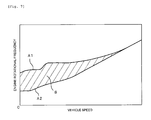
- a region (hatched region) S of speed change is set by a V-N characteristic curve A1 in the case where an accelerator is fully opened to perform acceleration under the condition of a normal load (in the case where one person takes a vehicle on a flat road), and a V-N characteristic curve A2 in the case where an accelerator is fully closed to perform deceleration under such condition, and a speed change ratio is set so that V-N characteristics (in Fig. 7, a point prescribed by a vehicle speed, which is a parameter on the abscissa, and an engine rotational frequency, which is a parameter on the ordinate) does not deviate from the region S of speed change. That is, conventionally, deviation from the region S of speed change does not occur even at the time of acceleration from a stopping state and at the time of acceleration during traveling.
- Such electronic controlled type continuously variable transmissions there is known one, in which a plurality of operation modes are beforehand prepared and a driver performs an operation of mode switching to modify the V-N characteristics stepwise.
- a transmission in which two kinds of operation modes, that is, a normal mode and a power mode, which attaches greater importance to quality of acceleration than that with the normal mode, and when a driver switches a mode selection switch from the normal mode to the power mode, a speed change ratio is modified to be rather large (Low side) and an engine rotational frequency is controlled to be rather high in a range of the region of speed change.
- the following Japanese Patent No. 2950957 discloses a continuously variable transmission provided with a manual type reduction lever, in which a speed change ratio is optionally adjustable in a predetermined region of speed change.
- the reduction lever can be set to an optional position between a fully closed position and a fully opened position. Therefore, it is possible to minutely regulate a speed change ratio unlike the related art, in which a speed change ratio can be regulated only stepwise.
- a driver manipulates the reduction lever at the time of rapid acceleration to enable making an engine rotational frequency a high value as intended by the driver.
- the continuously variable transmission includes, so to speak, an infinite number of operation modes and a driver can optionally switch the operation modes.
- the invention has been thought of in view of such point and has its object to provide a controller of a continuously variable transmission, which can sufficiently make use of an engine performance inherent in a motorcycle or the like.
- a controller of a continuously variable transmission mounted on a vehicle with a speed change ratio controller comprising a standard speed change ratio setting unit setting a target speed change ratio of the transmission on the basis of a manipulated variable of an accelerator manipulating element and/or a load on the vehicle, a specific speed change ratio setting unit, which sets when the manipulated variable of the accelerator manipulating element and/or the load on the vehicle exceeds the respective standard ranges, a target speed change ratio so that the V-N characteristics get out of a predetermined region of speed change, and an automatic return unit, which resets a target speed change ratio whereby the V-N characteristics having gotten out of a predetermined region of speed automatically return to the predetermined region of speed change.
- the invented controller of a continuously variable transmission beneficially attains a desired acceleration or deceleration even when a driver does not make a troublesome manipulation.
- the invented controller beneficially prevents continuation of an operation in a state, in which an engine rotational frequency is higher than normal, over a long period of time after a desired acceleration or deceleration is attained.
- the controller of a continuously variable transmission is mounted on a vehicle, which includes an engine and an accelerator manipulating element manipulated by hand, and the controller comprises an accelerator manipulated variable detector that detects a manipulated variable of the accelerator manipulating element, and the speed change ratio controller that sets a target speed change ratio of the continuously variable transmission on the basis of a manipulated variable of the accelerator manipulating element and controls the continuously variable transmission so that a speed change ratio becomes the target speed change ratio, and wherein the speed change ratio controller comprises the standard speed change ratio setting unit that sets a target speed change ratio so that V-N characteristics prescribed by a vehicle speed and an engine rotational frequency falls in a predetermined region of speed change, when a manipulated variable of the accelerator manipulating element is in a predetermined standard range, the specific speed change ratio setting unit that sets a target speed change ratio so that the V-N characteristics get out of the predetermined region of speed change, when a manipulated variable of the accelerator manipulating element exceeds the standard range, and the automatic return unit that resets a target speed change ratio
- the controller of a continuously variable transmission is mounted on a vehicle, which includes an engine and an accelerator manipulating element manipulated by hand, and the controller comprising a load detector that detects a load on the vehicle, and the speed change ratio controller that sets a target speed change ratio of the continuously variable transmission on the basis of the load on the vehicle and controls the continuously variable transmission so that a speed change ratio becomes the target speed change ratio
- the speed change ratio controller comprises the standard speed change ratio setting unit that sets a target speed change ratio so that V-N characteristics prescribed by a vehicle speed and an engine rotational frequency falls in a predetermined region of speed change, when the load on the vehicle is in a predetermined standard range, the specific speed change ratio setting unit that sets a target speed change ratio so that the V-N characteristics get out of the predetermined region of speed change, when the load on the vehicle exceeds the standard range, and the automatic return unit that resets a target speed change ratio so that the V-N characteristics having gotten out of the predetermined region of speed return to the predetermined region of
- the controller of a continuously variable transmission is mounted on a vehicle, which includes an engine and an accelerator manipulating element manipulated by hand, and the controller comprising an accelerator manipulated variable detector that detects a manipulated variable of the accelerator manipulating element, a load detector that detects a load on the vehicle, and the speed change ratio controller that sets a target speed change ratio of the continuously variable transmission on the basis of a manipulated variable of the accelerator manipulating element and the load on the vehicle and controls the continuously variable transmission so that a speed change ratio becomes the target speed change ratio
- the speed change ratio controller comprises the standard speed change ratio setting unit that sets a target speed change ratio so that the V-N characteristics prescribed by a vehicle speed and an engine rotational frequency falls in a predetermined region of speed change, when a manipulated variable of the accelerator manipulating element or the load on the vehicle is in a predetermined standard range, the specific speed change ratio setting unit that sets a target speed change ratio so that the V-N characteristics get out of the predetermined region of speed change, when a
- the speed change ratio controller further comprises a storage unit, which stores predetermined speed change ratio information, the standard speed change ratio setting unit sets a target speed change ratio according to the speed change ratio information, and the specific speed change ratio setting unit calculates a correction for the target speed change ratio, which is set by the standard speed change ratio setting unit, on the basis of a manipulated variable of the accelerator manipulating element and sets a value, which is obtained by correcting the target speed change ratio on the basis of the correction, as a new target speed change ratio when a manipulated variable of the accelerator manipulating element exceeds the standard range.
- the speed change ratio controller further comprises a storage unit, which stores predetermined speed change ratio information, the standard speed change ratio setting unit sets a target speed change ratio according to the speed change ratio information, and the specific speed change ratio setting unit calculates a correction for the target speed change ratio, which is set by the standard speed change ratio setting unit, on the basis of the load on the vehicle and sets a value, which is obtained by correcting the target speed change ratio on the basis of the correction, as a new target speed change ratio when the load on the vehicle exceeds the standard range.
- a storage unit which stores predetermined speed change ratio information
- the standard speed change ratio setting unit sets a target speed change ratio according to the speed change ratio information
- the specific speed change ratio setting unit calculates a correction for the target speed change ratio, which is set by the standard speed change ratio setting unit, on the basis of the load on the vehicle and sets a value, which is obtained by correcting the target speed change ratio on the basis of the correction, as a new target speed change ratio when the load on the vehicle exceeds the standard range.
- the speed change ratio controller further comprises a storage unit, which stores predetermined speed change ratio information, the standard speed change ratio setting unit sets a target speed change ratio according to the speed change ratio information, and the specific speed change ratio setting unit calculates a correction for the target speed change ratio, which is set by the standard speed change ratio setting unit, on the basis of a manipulated variable of the accelerator manipulating element and the load on the vehicle and sets a value, which is obtained by correcting the target speed change ratio on the basis of the correction, as a new target speed change ratio when a manipulated variable of the accelerator manipulating element and the load on the vehicle exceed the standard ranges.
- a storage unit which stores predetermined speed change ratio information
- the standard speed change ratio setting unit sets a target speed change ratio according to the speed change ratio information
- the specific speed change ratio setting unit calculates a correction for the target speed change ratio, which is set by the standard speed change ratio setting unit, on the basis of a manipulated variable of the accelerator manipulating element and the load on the vehicle and sets a value, which is obtained by correct
- the continuously variable transmission comprises a primary sheave, a secondary sheave, and a transmission belt wound around the primary sheave and the secondary sheave, and further comprising a vehicle speed detector that detects a travel speed of the vehicle, an engine rotational frequency detector that detects a rotational frequency of the engine, and a secondary sheave rotational frequency detector that detects a rotational frequency of the secondary sheave
- the speed change ratio controller comprises a storage unit, which stores predetermined speed change ratio information
- the standard speed change ratio setting unit sets a target speed change ratio according to the speed change ratio information on the basis of a manipulated variable of the accelerator manipulating element and the travel speed
- the specific speed change ratio setting unit calculates a correction for the target speed change ratio, which is set by the standard speed change ratio setting unit, on the basis of a manipulated variable of the accelerator manipulating element, the travel speed, the engine rotational frequency, and the secondary sheave rotational frequency and sets a value, which is obtained by correcting the target speed change ratio
- the automatic return unit begins resetting of the speed change ratio when a manipulated variable of the accelerator manipulating element becomes equal to or less than a predetermined amount after the vehicle accelerates and the V-N characteristics get out of the predetermined region of speed change.
- the automatic return unit begins resetting of the speed change ratio when a decrease in a manipulated variable of the accelerator manipulating element becomes equal to or more than a predetermined amount after the vehicle accelerates and the V-N characteristics get out of the predetermined region of speed change.
- the automatic return unit begins resetting of the speed change ratio when a manipulated variable of the accelerator manipulating element becomes equal to or more than a predetermined amount after the vehicle decelerates and the V-N characteristics get out of the predetermined region of speed change.
- the automatic return unit begins resetting of the speed change ratio when an increase in a manipulated variable of the accelerator manipulating element becomes equal to or more than a predetermined amount after the vehicle decelerates and the V-N characteristics get out of the predetermined region of speed change.
- the controller further comprises an acceleration detector that detects acceleration of the vehicle, and wherein the automatic return unit begins resetting of the speed change ratio when the acceleration becomes equal to or less than a predetermined value due to a driver's manipulation after the vehicle accelerates and the V-N characteristics get out of the predetermined region of speed change.
- the controller further comprises an acceleration detector that detects acceleration of the vehicle, and wherein the automatic return unit begins resetting of the speed change ratio when a decrease in the acceleration becomes equal to or more than a predetermined amount due to a driver's manipulation after the vehicle accelerates and the V-N characteristics get out of the predetermined region of speed change.
- the controller further comprises an acceleration detector that detects acceleration of the vehicle, and wherein the automatic return unit begins resetting of the speed change ratio when the acceleration becomes equal to or more than a predetermined value after the vehicle accelerates and the V-N characteristics get out of the predetermined region of speed change.
- the controller further comprises a vehicle speed detector that detects a travel speed of the vehicle, and wherein the automatic return unit begins resetting of the speed change ratio when the travel speed becomes equal to or less than a predetermined value due to a driver's manipulation after the vehicle accelerates and the V-N characteristics get out of the predetermined region of speed change.
- the controller further comprises a vehicle speed detector that detects a travel speed of the vehicle, and wherein the automatic return unit begins resetting of the speed change ratio when a decrease in the travel speed becomes equal to or more than a predetermined value due to a driver's manipulation after the vehicle accelerates and the V-N characteristics get out of the predetermined region of speed change.
- the controller further comprises a vehicle speed detector that detects a travel speed of the vehicle, and wherein the automatic return unit begins resetting of the speed change ratio when the travel speed becomes equal to or more than a predetermined value after the vehicle accelerates and the V-N characteristics get out of the predetermined region of speed change.
- the controller further comprises a vehicle speed detector that detects a travel speed of the vehicle, and wherein the automatic return unit begins resetting of the speed change ratio when the travel speed becomes equal to or more than a predetermined value due to a driver's manipulation after the vehicle decelerates and the V-N characteristics get out of the predetermined region of speed change.
- the controller further comprises a vehicle speed detector that detects a travel speed of the vehicle, and wherein the automatic return unit begins resetting of the speed change ratio when an increase in the travel speed becomes equal to or more than a predetermined amount due to a driver's manipulation after the vehicle decelerates and the V-N characteristics get out of the predetermined region of speed change.
- the controller further comprises a vehicle speed detector that detects a travel speed of the vehicle, and wherein the automatic return unit begins resetting of the speed change ratio when the travel speed becomes equal to or less than a predetermined value after the vehicle decelerates and the V-N characteristics get out of the region of speed change.
- the controller further comprises an engine rotational frequency detector that detects a rotational frequency of the engine, and wherein the automatic return unit begins resetting of the speed change ratio when an engine rotational frequency becomes equal to or less than a predetermined value due to a driver's manipulation after the vehicle accelerates or decelerates and the V-N characteristics get out of the predetermined region of speed change.
- the controller further comprises an engine rotational frequency detector that detects a rotational frequency of the engine, and wherein the automatic return unit begins resetting of the speed change ratio when a decrease in engine rotational frequency becomes equal to or more than a predetermined amount due to a driver's manipulation after the vehicle accelerates or decelerates and the V-N characteristics get out of the predetermined region of speed change.
- the controller further comprises an engine rotational frequency detector that detects a rotational frequency of the engine, and wherein the automatic return unit begins resetting of the speed change ratio when an engine rotational frequency becomes equal to or more than a predetermined value after the vehicle accelerates or decelerates and the V-N characteristics get out of the predetermined region of speed change.
- the controller further comprises a timer capable of measuring an elapsed time, and wherein the automatic return unit begins resetting of the speed change ratio when a predetermined time elapses after the V-N characteristics get out of the predetermined region of speed change.
- the controller further comprises a timer capable of measuring an elapsed time, and wherein the automatic return unit begins resetting of the speed change ratio when a predetermined time elapses after the V-N characteristics get out of the predetermined region of speed change.
- the specific speed change ratio setting unit sets a target speed change ratio so that the V-N characteristics get out of the predetermined region of speed change.
- the specific speed change ratio setting unit sets a target speed change ratio so that the V-N characteristics get out of the predetermined region of speed change.
- the vehicle comprises an engine and an accelerator manipulating element, and is provided with the controller of a continuously variable transmission, according to one of the above embodiments.
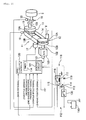
- a vehicle according to the embodiment is a scooter type motorcycle 1.
- the motorcycle 1 comprises a vehicle body 5, an engine 100 mounted to the vehicle body 5, a front wheel 3, a rear wheel 2, and a steering handle 4.
- a V-belt type continuously variable transmission 11 is arranged in a power transmission path between the engine 100 and the rear wheel 2.
- the continuously variable transmission 11 comprises a primary sheave 12, a secondary sheave 13, and a V-belt 14 wound around the primary sheave 12 and the secondary sheave 13.
- the primary sheave 12 is connected to a primary shaft 102 (for example, a crankshaft) that rotates as the engine 100 rotates.
- the secondary sheave 13 is connected to a secondary shaft 103 that outputs a motive power to the rear wheel 2 (drive wheel) through a centrifugal clutch 15 and a speed reducer 16.
- the primary sheave 12 includes a stationary sheave 12A and a moving sheave 12B, and a V-groove is formed between the stationary sheave 12A and the moving sheave 12B to interpose the V-belt 14.
- the secondary sheave 13 also includes a stationary sheave 13A and a moving sheave 13B, and a V-groove is also formed between the stationary sheave 13A and the moving sheave 13B to interpose the V-belt 14.
- Driving force of the engine 100 is transmitted to the rear wheel 2 through the primary sheave 12, the V-belt 14, and the secondary sheave 13.
- the continuously variable transmission 11 comprises, as a device that regulates a speed change ratio, a sheave position shifting device 17 that axially shifts the moving sheave 12B of the primary sheave 12. While illustration is omitted, the sheave position shifting device 17 comprises an electric motor that shifts the moving sheave 12B. However, the sheave position shifting device 17 is in no way limited in specific construction. A drive source that shifts the moving sheave 12B is not limited to an electric motor.
- the steering handle 4 of the motorcycle 1 is provided with an accelerator grip 6 as an accelerator manipulating element, which is manipulated by driver's hands.
- the accelerator grip 6 is constructed to be rotatable between a fully closed position and a fully opened position.
- an accelerator opening degree makes a manipulated variable of the accelerator manipulating element.
- an accelerator opening degree increases at the time of acceleration, and an accelerator opening degree decreases at the time of deceleration. Therefore, it can be said that an accelerator opening degree is a parameter representative of a driver's intention of acceleration or deceleration.
- an intake pipe 7 of the engine 100 of the motorcycle 1 is provided with a throttle valve 8, which is operated by the accelerator grip 6, and a throttle opening degree sensor 21, which detects an opening degree of the throttle valve 8.
- An opening degree of the throttle valve 8 is regulated according to an accelerator opening degree.
- the throttle opening degree sensor 21 detects an opening degree of the throttle valve 8 to thereby detect an accelerator opening degree indirectly.
- the throttle opening degree sensor 21 functions as an accelerator manipulated variable detection device that detects an accelerator opening degree.
- the accelerator manipulated variable detection device is in no way limited in construction.
- the accelerator manipulated variable detection device may be one that detects an accelerator opening degree directly.
- the continuously variable transmission 11 is provided with a sheave position detection device 18, which detects a position of the moving sheave 12B in an axial direction.
- a speed change ratio of the continuously variable transmission 11 is univocally determined. Accordingly, a speed change ratio of the continuously variable transmission 11 can be detected by the sheave position detection device 18.
- a secondary sheave rotational frequency sensor 19 which detects the rotational frequency of the secondary sheave 13
- a vehicle speed sensor 20 which detects the rotational frequency of the rear wheel 2 to thereby detect a running speed (vehicle speed)
- an engine rotational frequency sensor 101 which detects the rotational frequency of the engine 100.
- the motorcycle 1 may be provided with an exclusive acceleration sensor, which detects acceleration, an exclusive acceleration sensor can be omitted since it is possible to calculate an acceleration on the basis of a vehicle speed.
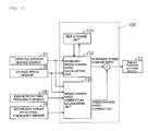
- a speed change ratio controller 120 which sets a target speed change ratio of the continuously variable transmission 11 and controls the sheave position shifting device 17 so that a speed change ratio of the continuously variable transmission 11 makes the target speed change ratio.
- the speed change ratio controller 120 is constructed to comprise a microcomputer as a main element.
- Input into the speed change ratio controller 120 are a main switch signal of a main switch 130, which controls ON/OFF of a general electric source of a vehicle, an engine rotational frequency signal output from the engine rotational frequency sensor 101, a throttle opening degree signal output from the throttle opening degree sensor 21, a secondary sheave rotational frequency signal output from the secondary sheave rotational frequency sensor 19, a vehicle speed signal output from the vehicle speed sensor 20, a sheave position signal output from the sheave position detection device 18, and the like.
- the speed change ratio controller 120 exercises control of the engine 100 and the continuously variable transmission 11 on the basis of various signals described above. In addition, details of control of the continuously variable transmission 11 will be described later.
- the speed change ratio controller 120 is supplied with electric power from an on-board electric source 110 through a feed line 112. Provided on the feed line 112 is a relay circuit 114 having a self-hold function.
- the relay circuit 114 comprises a relay switch 116, which controls supplying of electric power to the speed change ratio controller 120 from the on-board electric source 110, and a switch control element 117, which controls ON/OFF of the relay switch 116.
- the main switch 130 is made ON whereby a switch starting voltage is applied to the switch control element 117 via a first switch line 115.
- the switch control element 117 puts the relay switch 116 in a closed state from an opened state to close the feed line 112.
- electric power is supplied to the speed change ratio controller 120 from the on-board electric source 110 and the speed change ratio controller 120 is put in a state capable of being driven.
- the continuously variable transmission 11 specifically, the sheave position shifting device 17 operates to control a position of the moving sheave 12B, thereby enabling exercising control of speed change ratio.
- a second switch line 118 which supplies a switch starting voltage to the switch control element 117 to keep the relay switch 116 in a closed state. Until a predetermined condition stands even after the main switch 130 is made OFF, the second switch line 118 supplies a switch starting voltage to the switch control element 117 to keep the relay switch 116 in a closed state.
- the second switch line 118 is connected to a holding circuit 121 provided on the speed change ratio controller 120.
- the holding circuit 121 is composed of, for example, a capacitor, a diode, etc. and constructed to enable applying a voltage to the switch control element 117 via the second switch line 118 belonging to a separate system from that of the first switch line 115.
- the second switch line 118 is provided with a diode 119, which prevents reverse flow of electric current to the holding circuit 121 and flow of overcurrent to the holding circuit 121 via the second switch line 118 at the time of ON/OFF of the switch 130.
- the first switch line 115 is provided with a diode 113, which prevents the speed change ratio controller 120 from erroneously judging that an electric current flows to the speed change ratio controller 120 from the second switch line 118 at the time of OFF of the main switch 130 and so a main switch signal is made ON.
- the holding circuit 121 of the speed change ratio controller 120 is constructed to supply a voltage to the switch control element 117 via the second switch line 118 when supplying of a voltage from the on-board electric source 110 via the feed line 112 is started. More specifically, according to the embodiment, a voltage can be supplied to the switch control element 117 from lines of two systems, that is, the first switch line 115 via the switch 130 and the second switch line 118 via the holding circuit 121.
- the switch control element 117 is constructed to switch the relay switch 116 to a closed state from an opened state to maintain the state provided that a voltage is supplied from one of the first switch line 115 and the second switch line 118, and to switch the relay switch 116 to an opened state from a closed state to interrupt supplying of electric power to the speed change ratio controller 120 via the feed line 112 only in the case where no voltage is supplied from the both lines.
- the holding circuit 121 of the speed change ratio controller 120 continues to supply a voltage to the switch control element 117 via the second switch line 118 when a speed change ratio of the continuously variable transmission 11 is not Low, or the vehicle speed is not 0 at a point of time, at a point of time when the main switch 130 is made OFF.
- the speed change ratio controller 120 exercises normal control of speed change on the basis of a vehicle speed and a throttle opening degree until the vehicle speed becomes 0 also after the main switch 130 is made OFF.
- the speed change ratio controller 120 outputs an electric source cutting command to the holding circuit 121 at a stage, at which a vehicle speed becomes 0.
- the holding circuit 121 is constructed to interrupt supplying of voltage to the switch control element 117 via the second switch line 118 when an electric source cutting command is input thereinto from the speed change ratio controller 120 whereby the relay switch 116 is shifted to an opened state from a closed state and supplying of electric power to the speed change ratio controller 120 from the on-board electric source 110 is interrupted.
- the electric source is ensured until a speed change ratio becomes Low.
- the speed change ratio controller 120 comprises a map storage unit 131, which stores a predetermined speed change ratio map, a standard speed change ratio calculation unit 132, which calculates a speed change ratio (standard speed change ratio) according to the speed change ratio map, a speed change ratio correction calculation unit 133, which calculates a correction of speed change ratio, and a timer 134 (see Fig. 2) capable of measuring time elapsed from a predetermined reference time.
- the speed change ratio controller 120 normally exercises map control according to a predetermined speed change ratio map (STEP S1). While a specific construction of the change ratio map is in no way limited, the change ratio map according to the embodiment prescribes a standard target speed change ratio for a combination of a vehicle speed and a throttle opening degree.
- the target speed change ratio decreases (comes to a so-called Top side) as a vehicle speed increases while it conversely increases (comes to a so-called Low side) as a vehicle speed decreases.
- the target speed change ratio decreases as a throttle opening degree decreases while it conversely increases as a throttle opening degree increases.
- a standard target speed change ratio (referred below to as a standard speed change ratio) according to the change ratio map is set so that the V-N characteristics fall in a predetermined region of speed change.
- a target engine rotational frequency is calculated on the basis of a throttle opening degree signal from the throttle opening degree sensor 21 and a vehicle speed signal from the vehicle speed sensor 20. Subsequently, a target speed change ratio, at which a target engine rotational frequency is attained, is calculated according to the change ratio map.
- the sheave position shifting device 17 axially shifts the moving sheave 12B so that a speed change ratio of the continuously variable transmission 11 becomes the target speed change ratio.
- the speed change ratio controller 120 first determines a driver's intention of acceleration or deceleration in STEP S2.
- an accelerator opening degree is used as a parameter that reflects a driver's intention of acceleration or deceleration. Specifically, it is determined whether an accelerator opening degree falls in a predetermined range, and in case of being outside the predetermined range, the procedure proceeds to STEP S3. On the other hand, in the case where an accelerator opening degree falls in the predetermined range, the processing in STEP S2 is repeated. That is, it is judged that acceleration or deceleration at a standard speed change ratio is sufficient, and the map control is continued.
- StepEP S3 It is determined in STEP S3 whether a load on a vehicle falls in a predetermined range. In the case where the load on the vehicle falls in the predetermined range, the procedure proceeds to STEP S9 and a normal map control is continued. On the other hand, in the case where the load on the vehicle is larger than the predetermined range, it is judged that enough acceleration or deceleration is not obtained at the standard speed change ratio, and the procedure proceeds to STEP S4 on and after.
- factors in variation of a load on a vehicle include, for example, inclination of a slope of a travel path, a condition of a travel path, a vehicle weight (weight of cargo, driver, passenger, or the like), etc.
- a vehicle load can be calculated on the basis of vehicle traveling data such as vehicle speed, an accelerator opening degree, acceleration, engine rotational frequency, etc.
- a load detection device is constituted by the vehicle speed sensor 20, the engine rotational frequency sensor 101, etc.
- an acceleration sensor, an inclination sensor, which detects an inclination of a travel path, a torque sensor, etc. may be provided on the motorcycle 1 and a vehicle load may be calculated on the basis of signals from the sensors.
- Well known methods can be used for a method of calculating a vehicle load.
- a construction and a method for calculation of a vehicle load are in no way limited.
- a target speed change ratio is corrected so that the V-N characteristics get out of a predetermined region of speed change. More specifically, a correction relative to a standard speed change ratio is calculated on the basis of an operating state of a vehicle and a speed change ratio obtained by correcting the standard speed change ratio is made a new target speed change ratio.
- a correction of a target speed change ratio is calculated on the basis of a throttle opening degree, a vehicle speed, an engine rotational frequency, and a rotational frequency of the secondary sheave. In the case where an accelerator opening degree is large, or a vehicle load is large, a correction is calculated so that a target speed change ratio becomes large.
- the procedure proceeds to STEP S5.
- a standard speed change ratio is corrected on the basis of the correction.
- a speed change ratio after being corrected is set as a new target speed change ratio.
- the target speed change ratio is set so that the V-N characteristics get out of the predetermined region of speed change. In other words, a target speed change ratio is set in STEP S5 without being restricted by a preset speed change region.
- a method for calculation of a target speed change ratio is in no way limited.
- An increase in a speed change ratio may be calculated as a correction in STEP S4 and a target speed change ratio may be calculated by adding the increase to a standard speed change ratio in STEP S5.
- a correction factor may be calculated as a correction in STEP S4 and a target speed change ratio may be calculated by multiplying a standard speed change ratio by the correction factor in STEP S5.
- the STEP S2 to STEP S6 constitute a specific speed change ratio setting unit that sets a target speed change ratio so that the V-N characteristics get out of the region of speed change.
- STEP S7 in which a control signal is output to the sheave position shifting device 17 from the speed change ratio controller 120 so that a speed change ratio of the continuously variable transmission 11 becomes a target speed change ratio.
- the sheave position shifting device 17 axially shifts the moving sheave 12B to thereby regulate a speed change ratio.
- STEP S8 it is determined on the basis of a predetermined condition in STEP S8 whether acceleration or deceleration should be continued.
- the procedure returns to STEP S3.
- a target speed change ratio is reset so as to cause returning to map control based on a standard speed change ratio. Consequently, a normal map control is exercised (STEP S9) and the V-N characteristics having gotten out of the predetermined region of speed change automatically return to the region of speed change.
- the STEP S8 and STEP S9 constitute an automatic return unit that resets a target speed change ratio so that the V-N characteristics having gotten out of the region of speed return to the region of speed change.
- a condition of determination of continuation in STEP S8 can be adopted for a condition of determination of continuation in STEP S8.
- the necessity of continuation may be determined on the basis of an accelerator opening degree.
- a driver performs manipulation of returning the accelerator grip 6 so as to decrease acceleration.
- the procedure may proceed to STEP S9 to begin resetting of a target speed change ratio.
- resetting of a target speed change ratio may be begun on the basis of variation (for example, an increase or a decrease per unit time, i.e., an accelerator speed) in accelerator opening degree instead of an accelerator opening degree itself.
- variation for example, an increase or a decrease per unit time, i.e., an accelerator speed
- resetting of a target speed change ratio may be begun.
- resetting of a target speed change ratio may be begun in the case where manipulation of retuning the accelerator grip 6 is performed after the accelerator grip 6 is suddenly opened, that is, after rapid acceleration is performed by making an accelerator opening degree equal to or more than the predetermined opening degree.
- a driver manipulates the accelerator grip 6 again in an opening direction so as to decrease deceleration.
- resetting of a target speed change ratio may be begun.
- manipulation of opening the accelerator grip 6 is performed after rapid deceleration is performed by making an accelerator opening degree equal to or less than the predetermined opening degree, resetting of a target speed change ratio may be begun.
- the determination of continuation described above may be made on the basis of acceleration of a vehicle. For example, when acceleration becomes equal to or less than a predetermined value due to a driver's manipulation (for example, a driver returns the accelerator grip 6, or applies the brake, or the like) after acceleration is once performed, resetting of a target speed change ratio may be begun presuming that further acceleration is not necessary. Also, when a decrease in acceleration becomes equal to or more than a predetermined value due to a driver's manipulation after acceleration is once performed, resetting of a target speed change ratio may be begun.
- a driver's manipulation for example, a driver returns the accelerator grip 6, or applies the brake, or the like
- resetting of a target speed change ratio may be begun presuming that acceleration is enough at that point of time and further acceleration is not necessary.
- the determination of continuation described above may be made on the basis of a travel speed. For example, when a travel speed becomes equal to or less than a predetermined value due to a driver's manipulation after acceleration is once performed, resetting of a target speed change ratio may be begun presuming that further acceleration is not necessary. Also, when a decrease in travel speed becomes equal to or more than a predetermined amount due to a driver's manipulation after acceleration is once performed, resetting of a target speed change ratio may be begun.
- resetting of a target speed change ratio may be begun presuming that further acceleration is not necessary at that point of time.
- a driver manipulates the accelerator grip 6 again to enable setting a target speed change ratio rather large again.
- resetting of a target speed change ratio may be begun presuming that further deceleration is not necessary. Also, when an increase in travel speed becomes equal to or more than a predetermined amount due to a driver's manipulation after deceleration is once performed, resetting of a target speed change ratio may be begun.
- the determination of continuation described above may be made on the basis of an engine rotational frequency. For example, when an engine rotational frequency becomes equal to or less than a predetermined value due to a driver's manipulation after a vehicle accelerates or decelerates once, resetting of a target speed change ratio may be begun presuming that further acceleration or deceleration is not necessary. Also, when a decrease in engine rotational frequency becomes equal to or more than a predetermined amount due to a driver's manipulation after acceleration or deceleration is effected once, resetting of a target speed change ratio may be begun.
- resetting of a target speed change ratio may be begun presuming that further acceleration or deceleration is not necessary at that point of time.
- the determination of continuation described above may be made on the basis of a predetermined elapsed time. For example, when the V-N characteristics get out of a predetermined region of speed change, or when a predetermined period of time elapses since a base time when a predetermined processing in STEP S4, or STEP S7, etc. is begun, resetting of a target speed change ratio may be begun presuming that further acceleration or deceleration is not necessary at that point of time.
- a region (hatched region) S surrounded by a characteristic curve A1 and a characteristic curve A2 in Fig. 7 represents a region of speed change of the continuously variable transmission 11.
- a target speed change ratio is set so that the V-N characteristics fall in the region S of speed change.
- the characteristic curve A1 and the characteristic curve A2, which define the region S of speed change are upper limit and lower limit characteristic curves in the range of map control.
- the characteristic curve A1 is one in the case where the accelerator is fully opened to perform acceleration under the condition of a normal load (in the case where one person takes a vehicle on a flat road).
- the characteristic curve A2 is one in the case where the accelerator is fully closed to perform deceleration under the condition of a normal load.
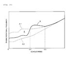
- Fig. 8 shows an example of a V-N characteristic curve B in the case where rapid acceleration is performed at the time of departure.
- a normal map control is exercised until a vehicle speed reaches V1 from 0, and the V-N characteristic curve B falls in the region S of speed change (on the characteristic curve A1).
- the V-N characteristic curve B gets out of the region S of speed change and a speed change ratio is corrected so that an engine rotational frequency increases. Consequently, a driver can get a feeling of enough acceleration.
- the V-N characteristic curve B returns into the region S of speed change (on the characteristic curve A1).
- the V-N characteristic curve B shown in Fig. 9 also represents the case where rapid acceleration is performed at the time of departure.
- a predetermined condition for example, a driver returns the accelerator grip 6, or a vehicle speed reaches a predetermined speed, or the like
- the V-N characteristic curve B returns into the region S of speed change at a point of time when a vehicle speed is V3.
- a normal map control is exercised and the V-N characteristic curve B remains in the region S of speed change.
- Fig. 10 shows an example of a V-N characteristic curve B in the case where acceleration is performed on an upward slope of large inclination.
- V3 it is judged from rapid acceleration at a vehicle speed V3 that an intention of acceleration is present to meet the condition of getting-out.
- Correction of a speed change ratio is begun with the result that the V-N characteristic curve B gets out of the region S of speed change from a point of time when a vehicle speed exceeds V4, and a speed change ratio is corrected so that an engine rotational frequency increases. Consequently, a driver can get a feeling of enough acceleration in spite of an upward slope of large inclination.
- a predetermined condition for example, a driver returns the accelerator grip 6, or acceleration reaches a predetermined speed, or the like
- the V-N characteristic curve B returns into the region S of speed change (on the characteristic curve A1).
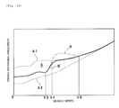
- Fig. 11 represents the case where rapid acceleration is made from a state (see a point C1) in the course of traveling.
- a speed change ratio is corrected judging that there is an intention of acceleration to meet the condition of getting-out at the time of acceleration. Consequently, at a point of time when a vehicle speed exceeds V6, the V-N characteristic curve B gets out of the region S of speed change and a speed change ratio is corrected so that an engine rotational frequency increases.
- the V-N characteristic curve B returns into the region S of speed change (on the characteristic curve A1).
- Fig. 12 is a flowchart schematically representing an example of a method for calculation of a speed change correction in STEP S4 (see Fig. 6). With the example, as shown in Fig.
- V-N characteristics are accelerated from the state point C2 to pass through a V-N characteristic curve B2, which is gentler in inclination than the V-N characteristic curve B1, to get out of the region S of speed change. Consequently, a feeling of acceleration conformed to a driver's intention is obtained and a ride is improved.
- Figs. 8, 9, 10, 11, and 13 show those examples, in all of which the V-N characteristics get out of predetermined regions of speed change.
- control of speed change according to the embodiment does not necessarily have V-N characteristics getting out of the region S of speed change at all times but, for example, in the case where an intention of acceleration is small, a V-N characteristic curve B' becomes steep in inclination temporarily as shown in Fig. 14 while it is consequently possible that deviation from the region S of speed change does not occur.
- a result see STEP S2 in Fig. 6
- deviation from the region S of speed change does not occur finally in some cases as a result of judging an intention of acceleration small.
- map control is usually exercised according to a speed change ratio map, which is beforehand registered, while when an accelerator opening degree and a vehicle load exceed predetermined reference ranges, a target speed change ratio is automatically corrected so that the V-N characteristics gets out of the region S of speed change. Therefore, it is possible to make positive use of a torque region of high engine performance to attain further acceleration or deceleration. Accordingly, it is possible to fully make use of an essential performance of the engine 100.
- deviation from the region S of speed change occurs in some cases even at the time of acceleration from a stopping state, and at the time of acceleration during traveling.
- a driver In the correction of a target speed change ratio, a driver is not required to perform a complex switching operation of a switch, etc. but can attain a desired acceleration or deceleration only through manipulation of the accelerator grip 6. Also, regulation of an accelerator opening degree makes it possible to freely select a normal map control and rapid acceleration or rapid deceleration, by which the V-N characteristics are caused to get out of the region S of speed change. Therefore, a driver can realize rapid acceleration and gentle acceleration only through manipulation of the accelerator. Also, since a complex switching operation is unnecessary, a driver can easily concentrate on driving.
- a target speed change ratio is automatically reset according to a predetermined condition so that the V-N characteristics returns into the region S of speed change. Therefore, an operation in a state, in which the V-N characteristics get out of the region S of speed change, is not continued for a long period of time. In other words, the V-N characteristics get out of the region S of speed change only during a predetermined period of time.
- the V-N characteristics automatically return into the region S of speed change, there does not occur a situation, in which a driver forgets returning, unlike the related art, in which an operation mode is switched by means of an operation switch, etc. Accordingly, an operation in a state, in which an engine rotational frequency is higher than normal after a predetermined acceleration is attained, can be prevented from continuing over a long period of time.
- an upper limit value and a lower limit value are beforehand set for a target speed change ratio to set that range of an effective speed change, which does not cause engine stall and engine over rev.
- a target speed change ratio is corrected, a target speed change ratio is made not to exceed an upper limit value and a lower limit value. Accordingly, it is possible to prevent excessive acceleration or deceleration while allowing the V-N characteristics to get out of the region S of speed change.
- a target speed change ratio may be corrected. For example, when an accelerator speed becomes equal to or larger than a predetermined speed, a target speed change ratio may be corrected. Also, a target speed change ratio may be corrected on the basis of both an accelerator opening degree and an accelerator speed. For example, in the case where an accelerator opening degree is equal to or larger than a predetermined amount and an accelerator speed is equal to or larger than a predetermined speed, a target speed change ratio may be corrected.
- control of speed change according to the embodiment calculates a speed change correction (see STEP S4) and corrects a standard speed change ratio to find a target speed change ratio.
- a method of setting a target speed change ratio so that V-N characteristics get out of the region S of speed change is not limited to the method according to the embodiment.
- one or two or more normal maps maps set so that V-N characteristics do not get out of the region S of speed change
- one or two or more special maps maps set so that V-N characteristics get out of the region S of speed change
- a map in use may be shifted to a special map from a normal map when a predetermined condition stands, and the special map may be automatically returned to the normal map when a predetermined condition of returning is established (automatic shifting of map).
- the special maps are strictly ones, which have V-N characteristics getting out of the region S of speed change, and not ones used in a normal range of control of speed change. Therefore, the special maps are different in quality from the normal maps.
- a vehicle with a controller of the continuously variable transmission 11 mounted thereon is a motorcycle 1.
- motorcycles referred to herein include a motorbicycle, a scooter, etc.
- a vehicle with the controller mounted thereon is not limited to the motorcycle 1.
- the vehicle may comprise ATV such as four-wheel buggy or the like.
- An accelerator manipulating element which is manipulated by hand, is not limited to an accelerator grip but may comprise other manipulating elements such as accelerator lever, or the like.
- a speed change ratio map is used as speed change ratio information in speed change control.
- speed change ratio information referred to in speed change control is not limited to map type information.
- speed change ratio information it is possible to make use of tabled information, information in the form of a function, other optional data construction, etc.
- the present teaching is useful for a vehicle (for example, a motorcycle, etc.) provided with an accelerator manipulating element, which is manipulated by hand, and a controller of a continuously variable transmission mounted on the vehicle.
- a vehicle for example, a motorcycle, etc.
- an accelerator manipulating element which is manipulated by hand
- a controller of a continuously variable transmission mounted on the vehicle.
- a controller of a continuously variable transmission mounted on a vehicle which includes an engine and an accelerator manipulating element manipulated by hand, the controller comprising an accelerator manipulated variable detector that detects a manipulated variable of the accelerator manipulating element, and a speed change ratio controller that sets a target speed change ratio of the continuously variable transmission on the basis of a manipulated variable of the accelerator manipulating element and controls the continuously variable transmission so that a speed change ratio becomes the target speed change ratio
- the speed change ratio controller comprises a standard speed change ratio setting unit that sets a target speed change ratio so that V-N characteristics prescribed by a vehicle speed and an engine rotational frequency falls in a predetermined region of speed change, when a manipulated variable of the accelerator manipulating element is in a predetermined standard range, a specific speed change ratio setting unit that sets a target speed change ratio so that the V-N characteristics get out of the predetermined region of speed change, when a manipulated variable of the accelerator manipulating element exceeds the standard range, and an automatic
- a controller of a continuously variable transmission mounted on a vehicle which includes an engine and an accelerator manipulating element manipulated by hand, the controller comprising a load detector that detects a load on the vehicle, and a speed change ratio controller that sets a target speed change ratio of the continuously variable transmission on the basis of the load on the vehicle and controls the continuously variable transmission so that a speed change ratio becomes the target speed change ratio
- the speed change ratio controller comprises a standard speed change ratio setting unit that sets a target speed change ratio so that V-N characteristics prescribed by a vehicle speed and an engine rotational frequency falls in a predetermined region of speed change, when the load on the vehicle is in a predetermined standard range, a specific speed change ratio setting unit that sets a target speed change ratio so that the V-N characteristics get out of the predetermined region of speed change, when the load on the vehicle exceeds the standard range, and an automatic return unit that resets a target speed change ratio so that the V-N characteristics having gotten out of the predetermined region of speed return
- a controller of a continuously variable transmission mounted on a vehicle which includes an engine and an accelerator manipulating element manipulated by hand, the controller comprising an accelerator manipulated variable detector that detects a manipulated variable of the accelerator manipulating element, a load detector that detects a load on the vehicle, and a speed change ratio controller that sets a target speed change ratio of the continuously variable transmission on the basis of a manipulated variable of the accelerator manipulating element and the load on the vehicle and controls the continuously variable transmission so that a speed change ratio becomes the target speed change ratio, and wherein the speed change ratio controller comprises a standard speed change ratio setting unit that sets a target speed change ratio so that the V-N characteristics prescribed by a vehicle speed and an engine rotational frequency falls in a predetermined region of speed change, when a manipulated variable of the accelerator manipulating element or the load on the vehicle is in a predetermined standard range, a specific speed change ratio setting unit that sets a target speed change ratio so that the V-N characteristics get out of the predetermined region of speed
- a target speed change ratio is set so that the V-N characteristics get out of the predetermined region of speed change.
- the automatic return unit resets a target speed change ratio whereby the V-N characteristics having gotten out of a predetermined region of speed automatically return to the region of speed change. Therefore, returning of the V-N characteristics to the predetermined region of speed change is not forgotten.
- a speed change ratio which exceeds a preset region of speed change, can be controlled, so that it is possible to sufficiently make use of an engine performance inherent to a motorcycle, etc.
- the V-N characteristics having gotten out of a predetermined region of speed automatically return to the region of speed change, so that it is possible to prevent continuation of an operation in a state, in which an engine rotational frequency is higher than normal, over a long period of time, for example, after a desired acceleration is attained.
- a speed change ratio controller which controls a speed change ratio of a continuously variable transmission, normally exercises map control according to a predetermined speed change ratio map so that a V-N characteristic curve prescribed by a vehicle speed (V) and an engine rotational frequency (N) falls in a range of a predetermined region of speed change (STEP S1).
- a target speed change ratio is corrected so that the V-N characteristic curve gets out of a predetermined region of speed change (STEP S4 to STEP S6).
- the necessity of continuation of acceleration or deceleration is determined on the basis of a predetermined condition such as returning of an accelerator grip or the like, and when the continuation is unnecessary, a normal map control is automatically restored.
- a controller of a continuously variable transmission mounted on a vehicle which includes an engine and an accelerator manipulating element manipulated by hand, the controller comprising an accelerator manipulated variable detector that detects a manipulated variable of the accelerator manipulating element, and a speed change ratio controller that sets a target speed change ratio of the continuously variable transmission on the basis of a manipulated variable of the accelerator manipulating element and controls the continuously variable transmission so that a speed change ratio becomes the target speed change ratio
- the speed change ratio controller comprises a standard speed change ratio setting unit that sets a target speed change ratio so that V-N characteristics prescribed by a vehicle speed and an engine rotational frequency falls in a predetermined region of speed change, when a manipulated variable of the accelerator manipulating element is in a predetermined standard range, a specific speed change ratio setting unit that sets a target speed change ratio so that the V-N characteristics get out of the predetermined region of speed change, when a manipulated variable of the accelerator manipulating element exceeds the standard range, and an automatic return unit that
- a controller of a continuously variable transmission mounted on a vehicle which includes an engine and an accelerator manipulating element manipulated by hand, the controller comprising a load detector that detects a load on the vehicle, and a speed change ratio controller that sets a target speed change ratio of the continuously variable transmission on the basis of the load on the vehicle and controls the continuously variable transmission so that a speed change ratio becomes the target speed change ratio
- the speed change ratio controller comprises a standard speed change ratio setting unit that sets a target speed change ratio so that V-N characteristics prescribed by a vehicle speed and an engine rotational frequency falls in a predetermined region of speed change, when the load on the vehicle is in a predetermined standard range, a specific speed change ratio setting unit that sets a target speed change ratio so that the V-N characteristics get out of the predetermined region of speed change, when the load on the vehicle exceeds the standard range, and an automatic return unit that resets a target speed change ratio so that the V-N characteristics having gotten out of the predetermined region of speed return
- a controller of a continuously variable transmission mounted on a vehicle which includes an engine and an accelerator manipulating element manipulated by hand, the controller comprising an accelerator manipulated variable detector that detects a manipulated variable of the accelerator manipulating element, a load detector that detects a load on the vehicle, and a speed change ratio controller that sets a target speed change ratio of the continuously variable transmission on the basis of a manipulated variable of the accelerator manipulating element and the load on the vehicle and controls the continuously variable transmission so that a speed change ratio becomes the target speed change ratio, and wherein the speed change ratio controller comprises a standard speed change ratio setting unit that sets a target speed change ratio so that the V-N characteristics prescribed by a vehicle speed and an engine rotational frequency falls in a predetermined region of speed change, when a manipulated variable of the accelerator manipulating element or the load on the vehicle is in a predetermined standard range, a specific speed change ratio setting unit that sets a target speed change ratio so that the V-N characteristics get out of the predetermined region of speed change
- the speed change ratio controller comprises a storage unit, which stores predetermined speed change ratio information, the standard speed change ratio setting unit sets a target speed change ratio according to the speed change ratio information, and the specific speed change ratio setting unit calculates a correction for the target speed change ratio, which is set by the standard speed change ratio setting unit, on the basis of a manipulated variable of the accelerator manipulating element and sets a value, which is obtained by correcting the target speed change ratio on the basis of the correction, as a new target speed change ratio when a manipulated variable of the accelerator manipulating element exceeds the standard range.
- the speed change ratio controller comprises a storage unit, which stores predetermined speed change ratio information, the standard speed change ratio setting unit sets a target speed change ratio according to the speed change ratio information, and the specific speed change ratio setting unit calculates a correction for the target speed change ratio, which is set by the standard speed change ratio setting unit, on the basis of the load on the vehicle and sets a value, which is obtained by correcting the target speed change ratio on the basis of the correction, as a new target speed change ratio when the load on the vehicle exceeds the standard range.
- the speed change ratio controller comprises a storage unit, which stores predetermined speed change ratio information, the standard speed change ratio setting unit sets a target speed change ratio according to the speed change ratio information, and the specific speed change ratio setting unit calculates a correction for the target speed change ratio, which is set by the standard speed change ratio setting unit, on the basis of a manipulated variable of the accelerator manipulating element and the load on the vehicle and sets a value, which is obtained by correcting the target speed change ratio on the basis of the correction, as a new target speed change ratio when a manipulated variable of the accelerator manipulating element and the load on the vehicle exceed the standard ranges.
- the continuously variable transmission comprises a primary sheave, a secondary sheave, and a transmission belt wound around the primary sheave and the secondary sheave, and further comprising a vehicle speed detector that detects a travel speed of the vehicle, an engine rotational frequency detector that detects a rotational frequency of the engine, and a secondary sheave rotational frequency detector that detects a rotational frequency of the secondary sheave
- the speed change ratio controller comprises a storage unit, which stores predetermined speed change ratio information
- the standard speed change ratio setting unit sets a target speed change ratio according to the speed change ratio information on the basis of a manipulated variable of the accelerator manipulating element and the travel speed
- the specific speed change ratio setting unit calculates a correction for the target speed change ratio, which is set by the standard speed change ratio setting unit, on the basis of a manipulated variable of the accelerator manipulating element, the travel speed, the engine rotational frequency, and the secondary sheave rotational frequency and sets a value, which is obtained by correcting the target speed
- the automatic return unit begins resetting of the speed change ratio when a manipulated variable of the accelerator manipulating element becomes equal to or less than a predetermined amount after the vehicle accelerates and the V-N characteristics get out of the predetermined region of speed change.
- the automatic return unit begins resetting of the speed change ratio when a decrease in a manipulated variable of the accelerator manipulating element becomes equal to or more than a predetermined amount after the vehicle accelerates and the V-N characteristics get out of the predetermined region of speed change.
- the automatic return unit begins resetting of the speed change ratio when a manipulated variable of the accelerator manipulating element becomes equal to or more than a predetermined amount after the vehicle decelerates and the V-N characteristics get out of the predetermined region of speed change.
- the automatic return unit begins resetting of the speed change ratio when an increase in a manipulated variable of the accelerator manipulating element becomes equal to or more than a predetermined amount after the vehicle decelerates and the V-N characteristics get out of the predetermined region of speed change.
- the controller further comprises an acceleration detector that detects acceleration of the vehicle, and wherein the automatic return unit begins resetting of the speed change ratio when the acceleration becomes equal to or less than a predetermined value due to a driver's manipulation after the vehicle accelerates and the V-N characteristics get out of the predetermined region of speed change.
- the controller further comprises an acceleration detector that detects acceleration of the vehicle, and wherein the automatic return unit begins resetting of the speed change ratio when a decrease in the acceleration becomes equal to or more than a predetermined amount due to a driver's manipulation after the vehicle accelerates and the V-N characteristics get out of the predetermined region of speed change.
- the controller further comprises an acceleration detector that detects acceleration of the vehicle, and wherein the automatic return unit begins resetting of the speed change ratio when the acceleration becomes equal to or more than a predetermined value after the vehicle accelerates and the V-N characteristics get out of the predetermined region of speed change.
- the controller further comprises a vehicle speed detector that detects a travel speed of the vehicle, and wherein the automatic return unit begins resetting of the speed change ratio when the travel speed becomes equal to or less than a predetermined value due to a driver's manipulation after the vehicle accelerates and the V-N characteristics get out of the predetermined region of speed change.
- the controller further comprises a vehicle speed detector that detects a travel speed of the vehicle, and wherein the automatic return unit begins resetting of the speed change ratio when a decrease in the travel speed becomes equal to or more than a predetermined value due to a driver's manipulation after the vehicle accelerates and the V-N characteristics get out of the predetermined region of speed change.
- the controller further comprises a vehicle speed detector that detects a travel speed of the vehicle, and wherein the automatic return unit begins resetting of the speed change ratio when the travel speed becomes equal to or more than a predetermined value after the vehicle accelerates and the V-N characteristics get out of the predetermined region of speed change.
- the controller further comprises a vehicle speed detector that detects a travel speed of the vehicle, and wherein the automatic return unit begins resetting of the speed change ratio when the travel speed becomes equal to or more than a predetermined value due to a driver's manipulation after the vehicle decelerates and the V-N characteristics get out of the predetermined region of speed change.
- the controller further comprises a vehicle speed detector that detects a travel speed of the vehicle, and wherein the automatic return unit begins resetting of the speed change ratio when an increase in the travel speed becomes equal to or more than a predetermined amount due to a driver's manipulation after the vehicle decelerates and the V-N characteristics get out of the predetermined region of speed change.
- the controller further comprises a vehicle speed detector that detects a travel speed of the vehicle, and wherein the automatic return unit begins resetting of the speed change ratio when the travel speed becomes equal to or less than a predetermined value after the vehicle decelerates and the V-N characteristics get out of the region of speed change.
- the controller further comprises an engine rotational frequency detector that detects a rotational frequency of the engine, and wherein the automatic return unit begins resetting of the speed change ratio when an engine rotational frequency becomes equal to or less than a predetermined value due to a driver's manipulation after the vehicle accelerates or decelerates and the V-N characteristics get out of the predetermined region of speed change.
- the controller further comprises an engine rotational frequency detector that detects a rotational frequency of the engine, and wherein the automatic return unit begins resetting of the speed change ratio when a decrease in engine rotational frequency becomes equal to or more than a predetermined amount due to a driver's manipulation after the vehicle accelerates or decelerates and the V-N characteristics get out of the predetermined region of speed change.
- the controller further comprises an engine rotational frequency detector that detects a rotational frequency of the engine, and wherein the automatic return unit begins resetting of the speed change ratio when an engine rotational frequency becomes equal to or more than a predetermined value after the vehicle accelerates or decelerates and the V-N characteristics get out of the predetermined region of speed change.
- the controller further comprises a timer capable of measuring an elapsed time, and wherein the automatic return unit begins resetting of the speed change ratio when a predetermined time elapses after the V-N characteristics get out of the predetermined region of speed change.
- the specific speed change ratio setting unit sets a target speed change ratio so that the V-N characteristics get out of the predetermined region of speed change.
- the specific speed change ratio setting unit sets a target speed change ratio so that the V-N characteristics get out of the predetermined region of speed change.
- the description above also discloses a vehicle comprising an engine and an accelerator manipulating element, and provided with the controller of a continuously variable transmission, according to any one of the above first to seventh aspects.
Abstract
Description
- The present invention relates to a controller of a continuously variable transmission mounted on a vehicle provided with an accelerator manipulating element, which is manipulated by hand, and a vehicle provided with the same.
- Conventionally, a V-belt type continuously variable transmission is used as a manipulating element for operation of acceleration or operation of deceleration in a vehicle, such as a scooter type motorcycle, etc., provided with an accelerator manipulating element (for example, an accelerator grip, an accelerator lever, etc.), which is manipulated by hand. A continuously variable transmission conventionally and frequently used is a so-called mechanical type continuously variable transmission, which comprises a centrifugal governor, and a speed change ratio is automatically regulated by a centrifugal force generated on the centrifugal governor at the time of rotation.
- With a motorcycle, etc., on which a mechanical type continuously variable transmission is mounted, an engine rotational frequency is fundamentally controlled by a throttle opening degree and a vehicle speed. With conventional motorcycles or the like, while a speed change ratio can be steplessly regulated by a continuously variable transmission, a speed change ratio is controlled so that V-N characteristics prescribed by a vehicle speed (V) and an engine rotational frequency (N) fall in a predetermined region of speed change. For example, as shown in Fig. 7, a region (hatched region) S of speed change is set by a V-N characteristic curve A1 in the case where an accelerator is fully opened to perform acceleration under the condition of a normal load (in the case where one person takes a vehicle on a flat road), and a V-N characteristic curve A2 in the case where an accelerator is fully closed to perform deceleration under such condition, and a speed change ratio is set so that V-N characteristics (in Fig. 7, a point prescribed by a vehicle speed, which is a parameter on the abscissa, and an engine rotational frequency, which is a parameter on the ordinate) does not deviate from the region S of speed change. That is, conventionally, deviation from the region S of speed change does not occur even at the time of acceleration from a stopping state and at the time of acceleration during traveling.
- However, a motorcycle, etc., on which a mechanical type continuously variable transmission is mounted, involves a problem that acceleration is slow at the time of acceleration on a steep, upward slope and at the time of acceleration with a double ride. Also, there is caused a problem that engine braking is hard to be effective when an accelerator is returned. Hereupon, there has been developed an electronic controlled type continuously variable transmission, in which a belt wound diameter of a sheave is controlled by an electric motor or the like so as to enable freely regulating a speed change ratio irrespective of a running state.
- Among such electronic controlled type continuously variable transmissions, there is known one, in which a plurality of operation modes are beforehand prepared and a driver performs an operation of mode switching to modify the V-N characteristics stepwise. For example, there is known a transmission, in which two kinds of operation modes, that is, a normal mode and a power mode, which attaches greater importance to quality of acceleration than that with the normal mode, and when a driver switches a mode selection switch from the normal mode to the power mode, a speed change ratio is modified to be rather large (Low side) and an engine rotational frequency is controlled to be rather high in a range of the region of speed change.
- However, only two kinds of operation modes are difficult to constantly generate a feeling of acceleration, by which a driver is satisfied. Hereupon, in order to meet a driver's request, it is conceivable to prepare a multiplicity of operation modes to permit a driver to appropriately select an operation mode according to a situation.
- The following
Japanese Patent No. 2950957 - However, conventional continuously variable transmissions mounted on motorcycles or the like can control a speed change ratio only within the limit of the region of speed change described above. Therefore, a whole region, in which speed change can be effectively attained, essentially included in a continuously variable transmission cannot be made use of, and so it cannot be said that an engine performance of a motorcycle or the like is made use of to the maximum.
- Also, with the conventional continuously variable transmission, in order to get enough acceleration at the time of traveling on a steep, upward slope, or the like, a driver is required to manipulate a mode selection switch, a reduction lever, etc. Therefore, manipulation made by a driver is made troublesome.
- Also, after an operation mode is switched to get a necessary acceleration, a driver forgets returning the mode selection switch, etc. in some cases. Therefore, an operation in a state, in which an engine rotational frequency is higher than normal, continues over a long period of time in some cases.
- The invention has been thought of in view of such point and has its object to provide a controller of a continuously variable transmission, which can sufficiently make use of an engine performance inherent in a motorcycle or the like.
- This objective is solved in an inventive manner by a controller of a continuously variable transmission mounted on a vehicle, with a speed change ratio controller comprising a standard speed change ratio setting unit setting a target speed change ratio of the transmission on the basis of a manipulated variable of an accelerator manipulating element and/or a load on the vehicle, a specific speed change ratio setting unit, which sets when the manipulated variable of the accelerator manipulating element and/or the load on the vehicle exceeds the respective standard ranges, a target speed change ratio so that the V-N characteristics get out of a predetermined region of speed change, and an automatic return unit, which resets a target speed change ratio whereby the V-N characteristics having gotten out of a predetermined region of speed automatically return to the predetermined region of speed change.
- The invented controller of a continuously variable transmission beneficially attains a desired acceleration or deceleration even when a driver does not make a troublesome manipulation.
- Further, the invented controller beneficially prevents continuation of an operation in a state, in which an engine rotational frequency is higher than normal, over a long period of time after a desired acceleration or deceleration is attained.
- According to a preferred embodiment, the controller of a continuously variable transmission is mounted on a vehicle, which includes an engine and an accelerator manipulating element manipulated by hand, and the controller comprises an accelerator manipulated variable detector that detects a manipulated variable of the accelerator manipulating element, and the speed change ratio controller that sets a target speed change ratio of the continuously variable transmission on the basis of a manipulated variable of the accelerator manipulating element and controls the continuously variable transmission so that a speed change ratio becomes the target speed change ratio, and wherein the speed change ratio controller comprises the standard speed change ratio setting unit that sets a target speed change ratio so that V-N characteristics prescribed by a vehicle speed and an engine rotational frequency falls in a predetermined region of speed change, when a manipulated variable of the accelerator manipulating element is in a predetermined standard range, the specific speed change ratio setting unit that sets a target speed change ratio so that the V-N characteristics get out of the predetermined region of speed change, when a manipulated variable of the accelerator manipulating element exceeds the standard range, and the automatic return unit that resets a target speed change ratio so that the V-N characteristics having gotten out of the predetermined region of speed return to the region of speed change.
- According to another preferred embodiment, the controller of a continuously variable transmission is mounted on a vehicle, which includes an engine and an accelerator manipulating element manipulated by hand, and the controller comprising a load detector that detects a load on the vehicle, and the speed change ratio controller that sets a target speed change ratio of the continuously variable transmission on the basis of the load on the vehicle and controls the continuously variable transmission so that a speed change ratio becomes the target speed change ratio, and wherein the speed change ratio controller comprises the standard speed change ratio setting unit that sets a target speed change ratio so that V-N characteristics prescribed by a vehicle speed and an engine rotational frequency falls in a predetermined region of speed change, when the load on the vehicle is in a predetermined standard range, the specific speed change ratio setting unit that sets a target speed change ratio so that the V-N characteristics get out of the predetermined region of speed change, when the load on the vehicle exceeds the standard range, and the automatic return unit that resets a target speed change ratio so that the V-N characteristics having gotten out of the predetermined region of speed return to the predetermined region of speed change.
- According to yet another preferred embodiment, the controller of a continuously variable transmission is mounted on a vehicle, which includes an engine and an accelerator manipulating element manipulated by hand, and the controller comprising an accelerator manipulated variable detector that detects a manipulated variable of the accelerator manipulating element, a load detector that detects a load on the vehicle, and the speed change ratio controller that sets a target speed change ratio of the continuously variable transmission on the basis of a manipulated variable of the accelerator manipulating element and the load on the vehicle and controls the continuously variable transmission so that a speed change ratio becomes the target speed change ratio, and wherein the speed change ratio controller comprises the standard speed change ratio setting unit that sets a target speed change ratio so that the V-N characteristics prescribed by a vehicle speed and an engine rotational frequency falls in a predetermined region of speed change, when a manipulated variable of the accelerator manipulating element or the load on the vehicle is in a predetermined standard range, the specific speed change ratio setting unit that sets a target speed change ratio so that the V-N characteristics get out of the predetermined region of speed change, when a manipulated variable of the accelerator manipulating element and the load on the vehicle exceed the standard ranges, and the automatic return unit that resets a target speed change ratio so that the V-N characteristics having gotten out of the predetermined region of speed return to the predetermined region of speed change.
- According to another embodiment, the speed change ratio controller further comprises a storage unit, which stores predetermined speed change ratio information, the standard speed change ratio setting unit sets a target speed change ratio according to the speed change ratio information, and the specific speed change ratio setting unit calculates a correction for the target speed change ratio, which is set by the standard speed change ratio setting unit, on the basis of a manipulated variable of the accelerator manipulating element and sets a value, which is obtained by correcting the target speed change ratio on the basis of the correction, as a new target speed change ratio when a manipulated variable of the accelerator manipulating element exceeds the standard range.
- According to another embodiment, the speed change ratio controller further comprises a storage unit, which stores predetermined speed change ratio information, the standard speed change ratio setting unit sets a target speed change ratio according to the speed change ratio information, and the specific speed change ratio setting unit calculates a correction for the target speed change ratio, which is set by the standard speed change ratio setting unit, on the basis of the load on the vehicle and sets a value, which is obtained by correcting the target speed change ratio on the basis of the correction, as a new target speed change ratio when the load on the vehicle exceeds the standard range.
- According to another embodiment, the speed change ratio controller further comprises a storage unit, which stores predetermined speed change ratio information, the standard speed change ratio setting unit sets a target speed change ratio according to the speed change ratio information, and the specific speed change ratio setting unit calculates a correction for the target speed change ratio, which is set by the standard speed change ratio setting unit, on the basis of a manipulated variable of the accelerator manipulating element and the load on the vehicle and sets a value, which is obtained by correcting the target speed change ratio on the basis of the correction, as a new target speed change ratio when a manipulated variable of the accelerator manipulating element and the load on the vehicle exceed the standard ranges.
- According to another embodiment, the continuously variable transmission comprises a primary sheave, a secondary sheave, and a transmission belt wound around the primary sheave and the secondary sheave, and further comprising a vehicle speed detector that detects a travel speed of the vehicle, an engine rotational frequency detector that detects a rotational frequency of the engine, and a secondary sheave rotational frequency detector that detects a rotational frequency of the secondary sheave, and wherein the speed change ratio controller comprises a storage unit, which stores predetermined speed change ratio information, the standard speed change ratio setting unit sets a target speed change ratio according to the speed change ratio information on the basis of a manipulated variable of the accelerator manipulating element and the travel speed, and the specific speed change ratio setting unit calculates a correction for the target speed change ratio, which is set by the standard speed change ratio setting unit, on the basis of a manipulated variable of the accelerator manipulating element, the travel speed, the engine rotational frequency, and the secondary sheave rotational frequency and sets a value, which is obtained by correcting the target speed change ratio on the basis of the correction, as a new target speed change ratio when a manipulated variable of the accelerator manipulating element and the load on the vehicle exceed the standard ranges.
- According to another embodiment, the automatic return unit begins resetting of the speed change ratio when a manipulated variable of the accelerator manipulating element becomes equal to or less than a predetermined amount after the vehicle accelerates and the V-N characteristics get out of the predetermined region of speed change.
- According to another embodiment, the automatic return unit begins resetting of the speed change ratio when a decrease in a manipulated variable of the accelerator manipulating element becomes equal to or more than a predetermined amount after the vehicle accelerates and the V-N characteristics get out of the predetermined region of speed change.
- According to another embodiment, the automatic return unit begins resetting of the speed change ratio when a manipulated variable of the accelerator manipulating element becomes equal to or more than a predetermined amount after the vehicle decelerates and the V-N characteristics get out of the predetermined region of speed change.
- According to another embodiment, the automatic return unit begins resetting of the speed change ratio when an increase in a manipulated variable of the accelerator manipulating element becomes equal to or more than a predetermined amount after the vehicle decelerates and the V-N characteristics get out of the predetermined region of speed change.
- According to another embodiment, the controller further comprises an acceleration detector that detects acceleration of the vehicle, and wherein the automatic return unit begins resetting of the speed change ratio when the acceleration becomes equal to or less than a predetermined value due to a driver's manipulation after the vehicle accelerates and the V-N characteristics get out of the predetermined region of speed change.
- According to another embodiment, the controller further comprises an acceleration detector that detects acceleration of the vehicle, and wherein the automatic return unit begins resetting of the speed change ratio when a decrease in the acceleration becomes equal to or more than a predetermined amount due to a driver's manipulation after the vehicle accelerates and the V-N characteristics get out of the predetermined region of speed change.
- According to another embodiment, the controller further comprises an acceleration detector that detects acceleration of the vehicle, and wherein the automatic return unit begins resetting of the speed change ratio when the acceleration becomes equal to or more than a predetermined value after the vehicle accelerates and the V-N characteristics get out of the predetermined region of speed change.
- According to another embodiment, the controller further comprises a vehicle speed detector that detects a travel speed of the vehicle, and wherein the automatic return unit begins resetting of the speed change ratio when the travel speed becomes equal to or less than a predetermined value due to a driver's manipulation after the vehicle accelerates and the V-N characteristics get out of the predetermined region of speed change.
- According to another embodiment, the controller further comprises a vehicle speed detector that detects a travel speed of the vehicle, and wherein the automatic return unit begins resetting of the speed change ratio when a decrease in the travel speed becomes equal to or more than a predetermined value due to a driver's manipulation after the vehicle accelerates and the V-N characteristics get out of the predetermined region of speed change.
- According to another embodiment, the controller further comprises a vehicle speed detector that detects a travel speed of the vehicle, and wherein the automatic return unit begins resetting of the speed change ratio when the travel speed becomes equal to or more than a predetermined value after the vehicle accelerates and the V-N characteristics get out of the predetermined region of speed change.
- According to another embodiment, the controller further comprises a vehicle speed detector that detects a travel speed of the vehicle, and wherein the automatic return unit begins resetting of the speed change ratio when the travel speed becomes equal to or more than a predetermined value due to a driver's manipulation after the vehicle decelerates and the V-N characteristics get out of the predetermined region of speed change.
- According to another embodiment, the controller further comprises a vehicle speed detector that detects a travel speed of the vehicle, and wherein the automatic return unit begins resetting of the speed change ratio when an increase in the travel speed becomes equal to or more than a predetermined amount due to a driver's manipulation after the vehicle decelerates and the V-N characteristics get out of the predetermined region of speed change.
- According to another embodiment, the controller further comprises a vehicle speed detector that detects a travel speed of the vehicle, and wherein the automatic return unit begins resetting of the speed change ratio when the travel speed becomes equal to or less than a predetermined value after the vehicle decelerates and the V-N characteristics get out of the region of speed change.
- According to another embodiment, the controller further comprises an engine rotational frequency detector that detects a rotational frequency of the engine, and wherein the automatic return unit begins resetting of the speed change ratio when an engine rotational frequency becomes equal to or less than a predetermined value due to a driver's manipulation after the vehicle accelerates or decelerates and the V-N characteristics get out of the predetermined region of speed change.
- According to another embodiment, the controller further comprises an engine rotational frequency detector that detects a rotational frequency of the engine, and wherein the automatic return unit begins resetting of the speed change ratio when a decrease in engine rotational frequency becomes equal to or more than a predetermined amount due to a driver's manipulation after the vehicle accelerates or decelerates and the V-N characteristics get out of the predetermined region of speed change.
- According to another embodiment, the controller further comprises an engine rotational frequency detector that detects a rotational frequency of the engine, and wherein the automatic return unit begins resetting of the speed change ratio when an engine rotational frequency becomes equal to or more than a predetermined value after the vehicle accelerates or decelerates and the V-N characteristics get out of the predetermined region of speed change.
- According to another embodiment, the controller further comprises a timer capable of measuring an elapsed time, and wherein the automatic return unit begins resetting of the speed change ratio when a predetermined time elapses after the V-N characteristics get out of the predetermined region of speed change.
- According to another embodiment, the controller further comprises a timer capable of measuring an elapsed time, and wherein the automatic return unit begins resetting of the speed change ratio when a predetermined time elapses after the V-N characteristics get out of the predetermined region of speed change.
- According to another embodiment, when a manipulated variable of the accelerator manipulating element becomes equal to or more than a predetermined amount in a state, in which a vehicle stops, the specific speed change ratio setting unit sets a target speed change ratio so that the V-N characteristics get out of the predetermined region of speed change.
- According to another embodiment, when a load on a vehicle becomes equal to or more than a predetermined value in a state, in which a vehicle travels, the specific speed change ratio setting unit sets a target speed change ratio so that the V-N characteristics get out of the predetermined region of speed change.
- According to a preferred embodiment, the vehicle comprises an engine and an accelerator manipulating element, and is provided with the controller of a continuously variable transmission, according to one of the above embodiments.
- In the following, the present invention is explained in greater detail with respect to several embodiments thereof in conjunction with the accompanying drawings, wherein:
- Fig. 1
- is a side view showing a motorcycle according to an embodiment,
- Fig. 2
- is block diagram showing a continuously variable transmission and a controller thereof,
- Fig. 3
- is a perspective view showing an accelerator grip,
- Fig. 4
- is a conceptual view showing a throttle valve and a throttle opening degree sensor,
- Fig. 5
- is block diagram showing a part of a construction of the controller,
- Fig. 6
- is a control flowchart of the continuously variable transmission,
- Fig. 7
- is a graph illustrating a region of speed change,
- Fig. 8
- is a graph illustrating an example of a V-N characteristic curve,
- Fig. 9
- is a graph illustrating a further example of a V-N characteristic curve,
- Fig. 10
- is a graph illustrating a further example of a V-N characteristic curve,
- Fig. 11
- is a graph illustrating a further example of a V-N characteristic curve,
- Fig. 12
- is a flowchart illustrating an example of a method of calculating a speed change correction,
- Fig. 13
- is a graph illustrating a further example of a V-N characteristic curve, and
- Fig. 14
- is a graph illustrating a further example of a V-N characteristic curve.
-
- 1: motorcycle (vehicle)
- 4: steering handle
- 6: accelerator grip (accelerator manipulating element)
- 8: throttle valve
- 11: continuously variable transmission
- 12: primary sheave
- 13: secondary sheave
- 14: V-belt
- 17: sheave position shifting device
- 100: engine
- 120: speed change ratio controller
- An embodiment will be described below in detail with reference to the drawings.
- As shown in Fig. 1, a vehicle according to the embodiment is a
scooter type motorcycle 1. Themotorcycle 1 comprises avehicle body 5, anengine 100 mounted to thevehicle body 5, afront wheel 3, arear wheel 2, and asteering handle 4. - As shown in Fig. 2, a V-belt type continuously
variable transmission 11 is arranged in a power transmission path between theengine 100 and therear wheel 2. The continuouslyvariable transmission 11 comprises aprimary sheave 12, asecondary sheave 13, and a V-belt 14 wound around theprimary sheave 12 and thesecondary sheave 13. Theprimary sheave 12 is connected to a primary shaft 102 (for example, a crankshaft) that rotates as theengine 100 rotates. Thesecondary sheave 13 is connected to asecondary shaft 103 that outputs a motive power to the rear wheel 2 (drive wheel) through a centrifugal clutch 15 and aspeed reducer 16. - The
primary sheave 12 includes astationary sheave 12A and a movingsheave 12B, and a V-groove is formed between thestationary sheave 12A and the movingsheave 12B to interpose the V-belt 14. Thesecondary sheave 13 also includes astationary sheave 13A and a movingsheave 13B, and a V-groove is also formed between thestationary sheave 13A and the movingsheave 13B to interpose the V-belt 14. Driving force of theengine 100 is transmitted to therear wheel 2 through theprimary sheave 12, the V-belt 14, and thesecondary sheave 13. - In the continuously
variable transmission 11, when the movingsheave 12B of theprimary sheave 12 or the movingsheave 13B of thesecondary sheave 13 is moved axially, the V-groove is varied in width to be varied in diameter, at which V-belt 14 is wound around therespective sheaves sheaves - The continuously
variable transmission 11 according to the embodiment comprises, as a device that regulates a speed change ratio, a sheaveposition shifting device 17 that axially shifts the movingsheave 12B of theprimary sheave 12. While illustration is omitted, the sheaveposition shifting device 17 comprises an electric motor that shifts the movingsheave 12B. However, the sheaveposition shifting device 17 is in no way limited in specific construction. A drive source that shifts the movingsheave 12B is not limited to an electric motor. - As shown in Fig. 3, the steering handle 4 of the
motorcycle 1 is provided with anaccelerator grip 6 as an accelerator manipulating element, which is manipulated by driver's hands. Theaccelerator grip 6 is constructed to be rotatable between a fully closed position and a fully opened position. Here, a position, to which theaccelerator grip 6 is rotated from the fully closed position, that is, an accelerator opening degree makes a manipulated variable of the accelerator manipulating element. Normally, an accelerator opening degree increases at the time of acceleration, and an accelerator opening degree decreases at the time of deceleration. Therefore, it can be said that an accelerator opening degree is a parameter representative of a driver's intention of acceleration or deceleration. - As shown in Fig. 4, an
intake pipe 7 of theengine 100 of themotorcycle 1 is provided with athrottle valve 8, which is operated by theaccelerator grip 6, and a throttleopening degree sensor 21, which detects an opening degree of thethrottle valve 8. An opening degree of thethrottle valve 8 is regulated according to an accelerator opening degree. - Therefore, the throttle
opening degree sensor 21 detects an opening degree of thethrottle valve 8 to thereby detect an accelerator opening degree indirectly. According to the embodiment, the throttleopening degree sensor 21 functions as an accelerator manipulated variable detection device that detects an accelerator opening degree. However, the accelerator manipulated variable detection device is in no way limited in construction. The accelerator manipulated variable detection device may be one that detects an accelerator opening degree directly. - As shown in Fig. 2, the continuously
variable transmission 11 is provided with a sheaveposition detection device 18, which detects a position of the movingsheave 12B in an axial direction. When a position of the movingsheave 12B is decided, a speed change ratio of the continuouslyvariable transmission 11 is univocally determined. Accordingly, a speed change ratio of the continuouslyvariable transmission 11 can be detected by the sheaveposition detection device 18. Also, provided on themotorcycle 1 are a secondary sheaverotational frequency sensor 19, which detects the rotational frequency of thesecondary sheave 13, avehicle speed sensor 20, which detects the rotational frequency of therear wheel 2 to thereby detect a running speed (vehicle speed), and an enginerotational frequency sensor 101, which detects the rotational frequency of theengine 100. In addition, while themotorcycle 1 may be provided with an exclusive acceleration sensor, which detects acceleration, an exclusive acceleration sensor can be omitted since it is possible to calculate an acceleration on the basis of a vehicle speed. - Provided on the
motorcycle 1 is a speedchange ratio controller 120, which sets a target speed change ratio of the continuouslyvariable transmission 11 and controls the sheaveposition shifting device 17 so that a speed change ratio of the continuouslyvariable transmission 11 makes the target speed change ratio. The speedchange ratio controller 120 is constructed to comprise a microcomputer as a main element. Input into the speedchange ratio controller 120 are a main switch signal of amain switch 130, which controls ON/OFF of a general electric source of a vehicle, an engine rotational frequency signal output from the enginerotational frequency sensor 101, a throttle opening degree signal output from the throttleopening degree sensor 21, a secondary sheave rotational frequency signal output from the secondary sheaverotational frequency sensor 19, a vehicle speed signal output from thevehicle speed sensor 20, a sheave position signal output from the sheaveposition detection device 18, and the like. The speedchange ratio controller 120 exercises control of theengine 100 and the continuouslyvariable transmission 11 on the basis of various signals described above. In addition, details of control of the continuouslyvariable transmission 11 will be described later. - The speed
change ratio controller 120 is supplied with electric power from an on-boardelectric source 110 through afeed line 112. Provided on thefeed line 112 is arelay circuit 114 having a self-hold function. - The
relay circuit 114 comprises arelay switch 116, which controls supplying of electric power to the speedchange ratio controller 120 from the on-boardelectric source 110, and aswitch control element 117, which controls ON/OFF of therelay switch 116. In therelay circuit 114, themain switch 130 is made ON whereby a switch starting voltage is applied to theswitch control element 117 via afirst switch line 115. - When a switch starting voltage is applied from the
first switch line 115, theswitch control element 117 puts therelay switch 116 in a closed state from an opened state to close thefeed line 112. Thereby, electric power is supplied to the speedchange ratio controller 120 from the on-boardelectric source 110 and the speedchange ratio controller 120 is put in a state capable of being driven. In a state, in which the speedchange ratio controller 120 can be driven, the continuouslyvariable transmission 11, specifically, the sheaveposition shifting device 17 operates to control a position of the movingsheave 12B, thereby enabling exercising control of speed change ratio. - Also, connected to the
relay circuit 114 according to the embodiment is asecond switch line 118, which supplies a switch starting voltage to theswitch control element 117 to keep therelay switch 116 in a closed state. Until a predetermined condition stands even after themain switch 130 is made OFF, thesecond switch line 118 supplies a switch starting voltage to theswitch control element 117 to keep therelay switch 116 in a closed state. - The
second switch line 118 is connected to a holdingcircuit 121 provided on the speedchange ratio controller 120. The holdingcircuit 121 is composed of, for example, a capacitor, a diode, etc. and constructed to enable applying a voltage to theswitch control element 117 via thesecond switch line 118 belonging to a separate system from that of thefirst switch line 115. In addition, thesecond switch line 118 is provided with adiode 119, which prevents reverse flow of electric current to the holdingcircuit 121 and flow of overcurrent to the holdingcircuit 121 via thesecond switch line 118 at the time of ON/OFF of theswitch 130. Likewise, thefirst switch line 115 is provided with adiode 113, which prevents the speedchange ratio controller 120 from erroneously judging that an electric current flows to the speedchange ratio controller 120 from thesecond switch line 118 at the time of OFF of themain switch 130 and so a main switch signal is made ON. - According to the embodiment, the holding
circuit 121 of the speedchange ratio controller 120 is constructed to supply a voltage to theswitch control element 117 via thesecond switch line 118 when supplying of a voltage from the on-boardelectric source 110 via thefeed line 112 is started. More specifically, according to the embodiment, a voltage can be supplied to theswitch control element 117 from lines of two systems, that is, thefirst switch line 115 via theswitch 130 and thesecond switch line 118 via the holdingcircuit 121. Theswitch control element 117 is constructed to switch therelay switch 116 to a closed state from an opened state to maintain the state provided that a voltage is supplied from one of thefirst switch line 115 and thesecond switch line 118, and to switch therelay switch 116 to an opened state from a closed state to interrupt supplying of electric power to the speedchange ratio controller 120 via thefeed line 112 only in the case where no voltage is supplied from the both lines. - Further, according to the embodiment, the holding
circuit 121 of the speedchange ratio controller 120 continues to supply a voltage to theswitch control element 117 via thesecond switch line 118 when a speed change ratio of the continuouslyvariable transmission 11 is not Low, or the vehicle speed is not 0 at a point of time, at a point of time when themain switch 130 is made OFF. - While voltage is supplied to the
switch control element 117 from thesecond switch line 118 and electric power is supplied from thefeed line 112, the speedchange ratio controller 120 exercises normal control of speed change on the basis of a vehicle speed and a throttle opening degree until the vehicle speed becomes 0 also after themain switch 130 is made OFF. The speedchange ratio controller 120 outputs an electric source cutting command to the holdingcircuit 121 at a stage, at which a vehicle speed becomes 0. The holdingcircuit 121 is constructed to interrupt supplying of voltage to theswitch control element 117 via thesecond switch line 118 when an electric source cutting command is input thereinto from the speedchange ratio controller 120 whereby therelay switch 116 is shifted to an opened state from a closed state and supplying of electric power to the speedchange ratio controller 120 from the on-boardelectric source 110 is interrupted. - According to the embodiment, even in the case where the
main switch 130 is made OFF by any chance when the V-N characteristics are put in a state of getting out of a predetermined region S of speed change (In addition, getting-out of the V-N characteristics will be described later in detail), the electric source is ensured until a speed change ratio becomes Low. - As shown in Fig. 5, the speed
change ratio controller 120 comprises amap storage unit 131, which stores a predetermined speed change ratio map, a standard speed changeratio calculation unit 132, which calculates a speed change ratio (standard speed change ratio) according to the speed change ratio map, a speed change ratiocorrection calculation unit 133, which calculates a correction of speed change ratio, and a timer 134 (see Fig. 2) capable of measuring time elapsed from a predetermined reference time. - Subsequently, control of speed change exercised by the speed
change ratio controller 120 will be described with reference to Fig. 6. - The speed
change ratio controller 120 normally exercises map control according to a predetermined speed change ratio map (STEP S1). While a specific construction of the change ratio map is in no way limited, the change ratio map according to the embodiment prescribes a standard target speed change ratio for a combination of a vehicle speed and a throttle opening degree. The target speed change ratio decreases (comes to a so-called Top side) as a vehicle speed increases while it conversely increases (comes to a so-called Low side) as a vehicle speed decreases. Also, the target speed change ratio decreases as a throttle opening degree decreases while it conversely increases as a throttle opening degree increases. However, a standard target speed change ratio (referred below to as a standard speed change ratio) according to the change ratio map is set so that the V-N characteristics fall in a predetermined region of speed change. - In the map control, a target engine rotational frequency is calculated on the basis of a throttle opening degree signal from the throttle
opening degree sensor 21 and a vehicle speed signal from thevehicle speed sensor 20. Subsequently, a target speed change ratio, at which a target engine rotational frequency is attained, is calculated according to the change ratio map. The sheaveposition shifting device 17 axially shifts the movingsheave 12B so that a speed change ratio of the continuouslyvariable transmission 11 becomes the target speed change ratio. - The speed
change ratio controller 120 first determines a driver's intention of acceleration or deceleration in STEP S2. Here, an accelerator opening degree is used as a parameter that reflects a driver's intention of acceleration or deceleration. Specifically, it is determined whether an accelerator opening degree falls in a predetermined range, and in case of being outside the predetermined range, the procedure proceeds to STEP S3. On the other hand, in the case where an accelerator opening degree falls in the predetermined range, the processing in STEP S2 is repeated. That is, it is judged that acceleration or deceleration at a standard speed change ratio is sufficient, and the map control is continued. - It is determined in STEP S3 whether a load on a vehicle falls in a predetermined range. In the case where the load on the vehicle falls in the predetermined range, the procedure proceeds to STEP S9 and a normal map control is continued. On the other hand, in the case where the load on the vehicle is larger than the predetermined range, it is judged that enough acceleration or deceleration is not obtained at the standard speed change ratio, and the procedure proceeds to STEP S4 on and after.
- In addition, factors in variation of a load on a vehicle include, for example, inclination of a slope of a travel path, a condition of a travel path, a vehicle weight (weight of cargo, driver, passenger, or the like), etc. A vehicle load can be calculated on the basis of vehicle traveling data such as vehicle speed, an accelerator opening degree, acceleration, engine rotational frequency, etc. According to the embodiment, a load detection device is constituted by the
vehicle speed sensor 20, the enginerotational frequency sensor 101, etc. Also, an acceleration sensor, an inclination sensor, which detects an inclination of a travel path, a torque sensor, etc. may be provided on themotorcycle 1 and a vehicle load may be calculated on the basis of signals from the sensors. Well known methods can be used for a method of calculating a vehicle load. A construction and a method for calculation of a vehicle load are in no way limited. - In STEP S4 on and after, a target speed change ratio is corrected so that the V-N characteristics get out of a predetermined region of speed change. More specifically, a correction relative to a standard speed change ratio is calculated on the basis of an operating state of a vehicle and a speed change ratio obtained by correcting the standard speed change ratio is made a new target speed change ratio. First, in STEP S4, a correction of a target speed change ratio is calculated on the basis of a throttle opening degree, a vehicle speed, an engine rotational frequency, and a rotational frequency of the secondary sheave. In the case where an accelerator opening degree is large, or a vehicle load is large, a correction is calculated so that a target speed change ratio becomes large. When a correction is calculated in STEP S4, the procedure proceeds to STEP S5.
- In STEP S5, a standard speed change ratio is corrected on the basis of the correction. A speed change ratio after being corrected is set as a new target speed change ratio. The target speed change ratio is set so that the V-N characteristics get out of the predetermined region of speed change. In other words, a target speed change ratio is set in STEP S5 without being restricted by a preset speed change region.
- In addition, a method for calculation of a target speed change ratio is in no way limited. An increase in a speed change ratio may be calculated as a correction in STEP S4 and a target speed change ratio may be calculated by adding the increase to a standard speed change ratio in STEP S5. Also, a correction factor may be calculated as a correction in STEP S4 and a target speed change ratio may be calculated by multiplying a standard speed change ratio by the correction factor in STEP S5. When a target speed change ratio is calculated in STEP S5, the procedure successively proceeds to STEP S6.
- By the way, when a vehicle is too large in acceleration or deceleration, there is a fear of causing engine stall and engine over rev. Hereupon, upper and lower limits of a speed change ratio are corrected in STEP S6. Specifically, it is determined whether a target speed change ratio calculated in STEP S5 falls in that range of an effective speed change ratio, which does not cause engine stall and engine over rev, and in case of falling in the range, the target speed change ratio calculated is made a new target speed change ratio while a preset upper limit or lower limit is made a new target speed change ratio in case of getting out of the range.
- In addition, the STEP S2 to STEP S6 constitute a specific speed change ratio setting unit that sets a target speed change ratio so that the V-N characteristics get out of the region of speed change.
- Subsequently, the procedure proceeds to STEP S7, in which a control signal is output to the sheave
position shifting device 17 from the speedchange ratio controller 120 so that a speed change ratio of the continuouslyvariable transmission 11 becomes a target speed change ratio. Receiving the control signal, the sheaveposition shifting device 17 axially shifts the movingsheave 12B to thereby regulate a speed change ratio. - Subsequently, it is determined on the basis of a predetermined condition in STEP S8 whether acceleration or deceleration should be continued. When it is determined that acceleration or deceleration should be continued, the procedure returns to STEP S3. On the other hand, when it is determined that it is unnecessary to continue acceleration or deceleration, a target speed change ratio is reset so as to cause returning to map control based on a standard speed change ratio. Consequently, a normal map control is exercised (STEP S9) and the V-N characteristics having gotten out of the predetermined region of speed change automatically return to the region of speed change. The STEP S8 and STEP S9 constitute an automatic return unit that resets a target speed change ratio so that the V-N characteristics having gotten out of the region of speed return to the region of speed change.
- Various conditions can be adopted for a condition of determination of continuation in STEP S8. For example, the necessity of continuation may be determined on the basis of an accelerator opening degree. Usually, in the case where enough acceleration is obtained at the time of acceleration, a driver performs manipulation of returning the
accelerator grip 6 so as to decrease acceleration. Hereupon, when an accelerator opening degree becomes equal to or less than a predetermined opening degree after acceleration, the procedure may proceed to STEP S9 to begin resetting of a target speed change ratio. - Also, resetting of a target speed change ratio may be begun on the basis of variation (for example, an increase or a decrease per unit time, i.e., an accelerator speed) in accelerator opening degree instead of an accelerator opening degree itself. For example, when a decrease (a decrease in manipulated variable of the accelerator manipulating element) in accelerator opening degree becomes equal to or more than a predetermined amount after acceleration, resetting of a target speed change ratio may be begun. For example, in the case where manipulation of retuning the
accelerator grip 6 is performed after theaccelerator grip 6 is suddenly opened, that is, after rapid acceleration is performed by making an accelerator opening degree equal to or more than the predetermined opening degree, resetting of a target speed change ratio may be begun. - Also, usually, in the case where enough deceleration is obtained at the time of deceleration, a driver manipulates the
accelerator grip 6 again in an opening direction so as to decrease deceleration. Hereupon, when an increase in accelerator opening degree becomes equal to or more than the predetermined amount after deceleration, resetting of a target speed change ratio may be begun. For example, in the case where manipulation of opening theaccelerator grip 6 is performed after rapid deceleration is performed by making an accelerator opening degree equal to or less than the predetermined opening degree, resetting of a target speed change ratio may be begun. - Also, the determination of continuation described above may be made on the basis of acceleration of a vehicle. For example, when acceleration becomes equal to or less than a predetermined value due to a driver's manipulation (for example, a driver returns the
accelerator grip 6, or applies the brake, or the like) after acceleration is once performed, resetting of a target speed change ratio may be begun presuming that further acceleration is not necessary. Also, when a decrease in acceleration becomes equal to or more than a predetermined value due to a driver's manipulation after acceleration is once performed, resetting of a target speed change ratio may be begun. - Also, conversely, when acceleration becomes equal to or more than the predetermined value after acceleration is once performed, resetting of a target speed change ratio may be begun presuming that acceleration is enough at that point of time and further acceleration is not necessary.
- Also, the determination of continuation described above may be made on the basis of a travel speed. For example, when a travel speed becomes equal to or less than a predetermined value due to a driver's manipulation after acceleration is once performed, resetting of a target speed change ratio may be begun presuming that further acceleration is not necessary. Also, when a decrease in travel speed becomes equal to or more than a predetermined amount due to a driver's manipulation after acceleration is once performed, resetting of a target speed change ratio may be begun.
- Also, conversely, when a vehicle accelerates and a travel speed becomes equal to or more than the predetermined value, resetting of a target speed change ratio may be begun presuming that further acceleration is not necessary at that point of time. In addition, in the case where further acceleration is necessary, a driver manipulates the
accelerator grip 6 again to enable setting a target speed change ratio rather large again. - Also, when a travel speed becomes equal to or more than the predetermined value due to a driver's manipulation after deceleration is once performed, resetting of a target speed change ratio may be begun presuming that further deceleration is not necessary. Also, when an increase in travel speed becomes equal to or more than a predetermined amount due to a driver's manipulation after deceleration is once performed, resetting of a target speed change ratio may be begun.
- Conversely, when a vehicle decelerates and a travel speed becomes equal to or less than the predetermined value, resetting of a target speed change ratio may be begun presuming that further deceleration is not necessary also at that point of time. The reason for this is that when a travel speed becomes low to a certain degree, it is possible to realize favorable deceleration or stoppage with a normal map control even when enough engine braking is not effected.
- Also, the determination of continuation described above may be made on the basis of an engine rotational frequency. For example, when an engine rotational frequency becomes equal to or less than a predetermined value due to a driver's manipulation after a vehicle accelerates or decelerates once, resetting of a target speed change ratio may be begun presuming that further acceleration or deceleration is not necessary. Also, when a decrease in engine rotational frequency becomes equal to or more than a predetermined amount due to a driver's manipulation after acceleration or deceleration is effected once, resetting of a target speed change ratio may be begun.
- Also, when a vehicle accelerates or decelerates and an engine rotational frequency becomes equal to or more than the predetermined value, resetting of a target speed change ratio may be begun presuming that further acceleration or deceleration is not necessary at that point of time.
- Also, the determination of continuation described above may be made on the basis of a predetermined elapsed time. For example, when the V-N characteristics get out of a predetermined region of speed change, or when a predetermined period of time elapses since a base time when a predetermined processing in STEP S4, or STEP S7, etc. is begun, resetting of a target speed change ratio may be begun presuming that further acceleration or deceleration is not necessary at that point of time.
- Subsequently, an explanation will be given to a modification of the V-N characteristics. A region (hatched region) S surrounded by a characteristic curve A1 and a characteristic curve A2 in Fig. 7 represents a region of speed change of the continuously
variable transmission 11. In exercising the map control, a target speed change ratio is set so that the V-N characteristics fall in the region S of speed change. In addition, the characteristic curve A1 and the characteristic curve A2, which define the region S of speed change, are upper limit and lower limit characteristic curves in the range of map control. According to the embodiment, the characteristic curve A1 is one in the case where the accelerator is fully opened to perform acceleration under the condition of a normal load (in the case where one person takes a vehicle on a flat road). On the other hand, the characteristic curve A2 is one in the case where the accelerator is fully closed to perform deceleration under the condition of a normal load. - Fig. 8 shows an example of a V-N characteristic curve B in the case where rapid acceleration is performed at the time of departure. In the example, a normal map control is exercised until a vehicle speed reaches V1 from 0, and the V-N characteristic curve B falls in the region S of speed change (on the characteristic curve A1). On the other hand, since a point of time, when a vehicle speed exceeds V1, the V-N characteristic curve B gets out of the region S of speed change and a speed change ratio is corrected so that an engine rotational frequency increases. Consequently, a driver can get a feeling of enough acceleration. When a vehicle speed reaches V2, the V-N characteristic curve B returns into the region S of speed change (on the characteristic curve A1).
- The V-N characteristic curve B shown in Fig. 9 also represents the case where rapid acceleration is performed at the time of departure. In the example, before a vehicle speed reaches V2 after a vehicle speed exceeds V1 and the V-N characteristic curve B gets out of the region S of speed change, a predetermined condition (for example, a driver returns the
accelerator grip 6, or a vehicle speed reaches a predetermined speed, or the like) is met and the V-N characteristic curve B returns into the region S of speed change at a point of time when a vehicle speed is V3. When a vehicle speed is equal to or larger than V3, a normal map control is exercised and the V-N characteristic curve B remains in the region S of speed change. - Fig. 10 shows an example of a V-N characteristic curve B in the case where acceleration is performed on an upward slope of large inclination. In the example, it is judged from rapid acceleration at a vehicle speed V3 that an intention of acceleration is present to meet the condition of getting-out. Correction of a speed change ratio is begun with the result that the V-N characteristic curve B gets out of the region S of speed change from a point of time when a vehicle speed exceeds V4, and a speed change ratio is corrected so that an engine rotational frequency increases. Consequently, a driver can get a feeling of enough acceleration in spite of an upward slope of large inclination. Before a vehicle speed reaches V5, a predetermined condition (for example, a driver returns the
accelerator grip 6, or acceleration reaches a predetermined speed, or the like) is met and at a point of time when a vehicle speed is V5, the V-N characteristic curve B returns into the region S of speed change (on the characteristic curve A1). - Fig. 11 represents the case where rapid acceleration is made from a state (see a point C1) in the course of traveling. In this example, a speed change ratio is corrected judging that there is an intention of acceleration to meet the condition of getting-out at the time of acceleration. Consequently, at a point of time when a vehicle speed exceeds V6, the V-N characteristic curve B gets out of the region S of speed change and a speed change ratio is corrected so that an engine rotational frequency increases. At a point of time when a vehicle speed reaches V2 after a predetermined condition of returning is met, the V-N characteristic curve B returns into the region S of speed change (on the characteristic curve A1).
- In addition, according to the embodiment, an amount of or a speed of getting-out from the region S of speed change may be of course changed corresponding to a manipulated variable of the accelerator or a vehicle load. Fig. 12 is a flowchart schematically representing an example of a method for calculation of a speed change correction in STEP S4 (see Fig. 6). With the example, as shown in Fig. 12, in calculation of a speed change correction, an extent (for example, a manipulated variable of the accelerator) of a driver's intention of acceleration or deceleration is determined (STEP S41), speed change correction is set large in the case where an extent of the intention is large (see STEP S42), and conversely, a speed change correction is set small in the case where an extent of the intention is small (see STEP S43). Thereby, as shown in, for example, Fig. 13, in the case where an extent of the intention is large, the V-N characteristics of a vehicle are rapidly accelerated from a state point C2 to pass through a steep V-N characteristic curve B1 to get out of the region S of speed change. On the other hand, in the case where an extent of the intention is small, the V-N characteristics are accelerated from the state point C2 to pass through a V-N characteristic curve B2, which is gentler in inclination than the V-N characteristic curve B1, to get out of the region S of speed change. Consequently, a feeling of acceleration conformed to a driver's intention is obtained and a ride is improved.
- In addition, Figs. 8, 9, 10, 11, and 13 show those examples, in all of which the V-N characteristics get out of predetermined regions of speed change. However, control of speed change according to the embodiment does not necessarily have V-N characteristics getting out of the region S of speed change at all times but, for example, in the case where an intention of acceleration is small, a V-N characteristic curve B' becomes steep in inclination temporarily as shown in Fig. 14 while it is consequently possible that deviation from the region S of speed change does not occur. For example, while it is judged as a result (see STEP S2 in Fig. 6) of determination of an intention of acceleration that an intention of acceleration is large, deviation from the region S of speed change does not occur finally in some cases as a result of judging an intention of acceleration small. Also, while an intention of acceleration is judged, deviation from the region S of speed change does not occur in some cases because of a small intention of acceleration. Further, deviation from the region S of speed change does not occur in some cases because a predetermined condition (see STEP S2) is not met.
- As described above, according to the embodiment, map control is usually exercised according to a speed change ratio map, which is beforehand registered, while when an accelerator opening degree and a vehicle load exceed predetermined reference ranges, a target speed change ratio is automatically corrected so that the V-N characteristics gets out of the region S of speed change. Therefore, it is possible to make positive use of a torque region of high engine performance to attain further acceleration or deceleration. Accordingly, it is possible to fully make use of an essential performance of the
engine 100. - In addition, according to the embodiment, unlike the related art, deviation from the region S of speed change occurs in some cases even at the time of acceleration from a stopping state, and at the time of acceleration during traveling.
- In the correction of a target speed change ratio, a driver is not required to perform a complex switching operation of a switch, etc. but can attain a desired acceleration or deceleration only through manipulation of the
accelerator grip 6. Also, regulation of an accelerator opening degree makes it possible to freely select a normal map control and rapid acceleration or rapid deceleration, by which the V-N characteristics are caused to get out of the region S of speed change. Therefore, a driver can realize rapid acceleration and gentle acceleration only through manipulation of the accelerator. Also, since a complex switching operation is unnecessary, a driver can easily concentrate on driving. - Also, according to the embodiment, since there is no need of beforehand preparing a multiplicity of operation modes, it is possible to make a control system simple in construction.
- According to the embodiment, after the V-N characteristics get out of the region S of speed change, a target speed change ratio is automatically reset according to a predetermined condition so that the V-N characteristics returns into the region S of speed change. Therefore, an operation in a state, in which the V-N characteristics get out of the region S of speed change, is not continued for a long period of time. In other words, the V-N characteristics get out of the region S of speed change only during a predetermined period of time.
- According to the embodiment, since the V-N characteristics automatically return into the region S of speed change, there does not occur a situation, in which a driver forgets returning, unlike the related art, in which an operation mode is switched by means of an operation switch, etc. Accordingly, an operation in a state, in which an engine rotational frequency is higher than normal after a predetermined acceleration is attained, can be prevented from continuing over a long period of time.
- According to the embodiment, while the V-N characteristics are allowed to get out of the region S of speed change, an upper limit value and a lower limit value are beforehand set for a target speed change ratio to set that range of an effective speed change, which does not cause engine stall and engine over rev. When a target speed change ratio is corrected, a target speed change ratio is made not to exceed an upper limit value and a lower limit value. Accordingly, it is possible to prevent excessive acceleration or deceleration while allowing the V-N characteristics to get out of the region S of speed change.
- In addition, according to the embodiment, it is determined on the basis of both an accelerator opening degree and a vehicle load whether a target speed change ratio should be corrected (see STEP S2 and STEP S3 in Fig. 6). However, it may be determined on the basis of an accelerator opening degree or a vehicle load whether a target speed change ratio should be corrected.
- Also, it may be determined on the basis of an accelerator speed or a vehicle load whether a target speed change ratio should be corrected. Further, it may be determined on the basis of an accelerator speed whether a target speed change ratio should be corrected. For example, when an accelerator speed becomes equal to or larger than a predetermined speed, a target speed change ratio may be corrected. Also, a target speed change ratio may be corrected on the basis of both an accelerator opening degree and an accelerator speed. For example, in the case where an accelerator opening degree is equal to or larger than a predetermined amount and an accelerator speed is equal to or larger than a predetermined speed, a target speed change ratio may be corrected.
- As shown in Fig. 6, when a predetermined condition (see STEP S2 and STEP S3) stands, control of speed change according to the embodiment calculates a speed change correction (see STEP S4) and corrects a standard speed change ratio to find a target speed change ratio. However, a method of setting a target speed change ratio so that V-N characteristics get out of the region S of speed change is not limited to the method according to the embodiment. For example, one or two or more normal maps (maps set so that V-N characteristics do not get out of the region S of speed change) and one or two or more special maps (maps set so that V-N characteristics get out of the region S of speed change) may be stored, a map in use may be shifted to a special map from a normal map when a predetermined condition stands, and the special map may be automatically returned to the normal map when a predetermined condition of returning is established (automatic shifting of map). In addition, the special maps are strictly ones, which have V-N characteristics getting out of the region S of speed change, and not ones used in a normal range of control of speed change. Therefore, the special maps are different in quality from the normal maps.
- According to the embodiment, a vehicle with a controller of the continuously
variable transmission 11 mounted thereon is amotorcycle 1. In addition, motorcycles referred to herein include a motorbicycle, a scooter, etc. However, a vehicle with the controller mounted thereon is not limited to themotorcycle 1. For example, the vehicle may comprise ATV such as four-wheel buggy or the like. - An accelerator manipulating element, which is manipulated by hand, is not limited to an accelerator grip but may comprise other manipulating elements such as accelerator lever, or the like.
- According to the embodiment, a speed change ratio map is used as speed change ratio information in speed change control. However, speed change ratio information referred to in speed change control is not limited to map type information. For speed change ratio information, it is possible to make use of tabled information, information in the form of a function, other optional data construction, etc.
- As described above, the present teaching is useful for a vehicle (for example, a motorcycle, etc.) provided with an accelerator manipulating element, which is manipulated by hand, and a controller of a continuously variable transmission mounted on the vehicle.
- The description above discloses (amongst others) an embodiment of a controller of a continuously variable transmission mounted on a vehicle, which includes an engine and an accelerator manipulating element manipulated by hand, the controller comprising an accelerator manipulated variable detector that detects a manipulated variable of the accelerator manipulating element, and a speed change ratio controller that sets a target speed change ratio of the continuously variable transmission on the basis of a manipulated variable of the accelerator manipulating element and controls the continuously variable transmission so that a speed change ratio becomes the target speed change ratio, and wherein the speed change ratio controller comprises a standard speed change ratio setting unit that sets a target speed change ratio so that V-N characteristics prescribed by a vehicle speed and an engine rotational frequency falls in a predetermined region of speed change, when a manipulated variable of the accelerator manipulating element is in a predetermined standard range, a specific speed change ratio setting unit that sets a target speed change ratio so that the V-N characteristics get out of the predetermined region of speed change, when a manipulated variable of the accelerator manipulating element exceeds the standard range, and an automatic return unit that resets a target speed change ratio so that the V-N characteristics having gotten out of the predetermined region of speed return to the predetermined region of speed change.
- Also, there is disclosed a further embodiment of a controller of a continuously variable transmission mounted on a vehicle, which includes an engine and an accelerator manipulating element manipulated by hand, the controller comprising a load detector that detects a load on the vehicle, and a speed change ratio controller that sets a target speed change ratio of the continuously variable transmission on the basis of the load on the vehicle and controls the continuously variable transmission so that a speed change ratio becomes the target speed change ratio, and wherein the speed change ratio controller comprises a standard speed change ratio setting unit that sets a target speed change ratio so that V-N characteristics prescribed by a vehicle speed and an engine rotational frequency falls in a predetermined region of speed change, when the load on the vehicle is in a predetermined standard range, a specific speed change ratio setting unit that sets a target speed change ratio so that the V-N characteristics get out of the predetermined region of speed change, when the load on the vehicle exceeds the standard range, and an automatic return unit that resets a target speed change ratio so that the V-N characteristics having gotten out of the predetermined region of speed return to the predetermined region of speed change.
- Also, there is discloses a further embodiment of a controller of a continuously variable transmission mounted on a vehicle, which includes an engine and an accelerator manipulating element manipulated by hand, the controller comprising an accelerator manipulated variable detector that detects a manipulated variable of the accelerator manipulating element, a load detector that detects a load on the vehicle, and a speed change ratio controller that sets a target speed change ratio of the continuously variable transmission on the basis of a manipulated variable of the accelerator manipulating element and the load on the vehicle and controls the continuously variable transmission so that a speed change ratio becomes the target speed change ratio, and wherein the speed change ratio controller comprises a standard speed change ratio setting unit that sets a target speed change ratio so that the V-N characteristics prescribed by a vehicle speed and an engine rotational frequency falls in a predetermined region of speed change, when a manipulated variable of the accelerator manipulating element or the load on the vehicle is in a predetermined standard range, a specific speed change ratio setting unit that sets a target speed change ratio so that the V-N characteristics get out of the predetermined region of speed change, when a manipulated variable of the accelerator manipulating element and the load on the vehicle exceed the standard ranges, and an automatic return unit that resets a target speed change ratio so that the V-N characteristics having gotten out of the predetermined region of speed return to the predetermined region of speed change.
- With the above embodiment of a controller, when a manipulated variable of the accelerator manipulating element or the load on the vehicle exceeds the standard ranges, a target speed change ratio is set so that the V-N characteristics get out of the predetermined region of speed change. Thereby, it is possible to get enough acceleration or deceleration, which cannot be gotten within the limit of a predetermined region of speed change. Also, a driver is not required to make a troublesome manipulation. Further, with the controller, the automatic return unit resets a target speed change ratio whereby the V-N characteristics having gotten out of a predetermined region of speed automatically return to the region of speed change. Therefore, returning of the V-N characteristics to the predetermined region of speed change is not forgotten.
- According to the present teaching, a speed change ratio, which exceeds a preset region of speed change, can be controlled, so that it is possible to sufficiently make use of an engine performance inherent to a motorcycle, etc.
- Also, since a switching operation of an operation mode, or the like is unnecessary, a desired acceleration or deceleration can be attained even when a driver does not make a troublesome manipulation.
- Further, according to the present teaching, the V-N characteristics having gotten out of a predetermined region of speed automatically return to the region of speed change, so that it is possible to prevent continuation of an operation in a state, in which an engine rotational frequency is higher than normal, over a long period of time, for example, after a desired acceleration is attained.
- Further, the description above discloses in order to provide a controller of a continuously variable transmission, which is capable of sufficiently making use of an essential engine performance of a motorcycle, etc., as a particularly preferred embodiment, a speed change ratio controller, which controls a speed change ratio of a continuously variable transmission, normally exercises map control according to a predetermined speed change ratio map so that a V-N characteristic curve prescribed by a vehicle speed (V) and an engine rotational frequency (N) falls in a range of a predetermined region of speed change (STEP S1). When an accelerator opening degree exceeds a predetermined range (STEP S2) and a vehicle load exceeds a predetermined range (STEP S3), a target speed change ratio is corrected so that the V-N characteristic curve gets out of a predetermined region of speed change (STEP S4 to STEP S6). After the V-N characteristic curve gets out of the region of speed change, the necessity of continuation of acceleration or deceleration is determined on the basis of a predetermined condition such as returning of an accelerator grip or the like, and when the continuation is unnecessary, a normal map control is automatically restored.
- The description above discloses as a preferred first aspect, a controller of a continuously variable transmission mounted on a vehicle, which includes an engine and an accelerator manipulating element manipulated by hand, the controller comprising an accelerator manipulated variable detector that detects a manipulated variable of the accelerator manipulating element, and a speed change ratio controller that sets a target speed change ratio of the continuously variable transmission on the basis of a manipulated variable of the accelerator manipulating element and controls the continuously variable transmission so that a speed change ratio becomes the target speed change ratio, and wherein the speed change ratio controller comprises a standard speed change ratio setting unit that sets a target speed change ratio so that V-N characteristics prescribed by a vehicle speed and an engine rotational frequency falls in a predetermined region of speed change, when a manipulated variable of the accelerator manipulating element is in a predetermined standard range, a specific speed change ratio setting unit that sets a target speed change ratio so that the V-N characteristics get out of the predetermined region of speed change, when a manipulated variable of the accelerator manipulating element exceeds the standard range, and an automatic return unit that resets a target speed change ratio so that the V-N characteristics having gotten out of the predetermined region of speed return to the region of speed change.
- As a preferred second aspect, there is disclosed a controller of a continuously variable transmission mounted on a vehicle, which includes an engine and an accelerator manipulating element manipulated by hand, the controller comprising a load detector that detects a load on the vehicle, and a speed change ratio controller that sets a target speed change ratio of the continuously variable transmission on the basis of the load on the vehicle and controls the continuously variable transmission so that a speed change ratio becomes the target speed change ratio, and wherein the speed change ratio controller comprises a standard speed change ratio setting unit that sets a target speed change ratio so that V-N characteristics prescribed by a vehicle speed and an engine rotational frequency falls in a predetermined region of speed change, when the load on the vehicle is in a predetermined standard range, a specific speed change ratio setting unit that sets a target speed change ratio so that the V-N characteristics get out of the predetermined region of speed change, when the load on the vehicle exceeds the standard range, and an automatic return unit that resets a target speed change ratio so that the V-N characteristics having gotten out of the predetermined region of speed return to the predetermined region of speed change.
- As a preferred third aspect, there is disclosed a controller of a continuously variable transmission mounted on a vehicle, which includes an engine and an accelerator manipulating element manipulated by hand, the controller comprising an accelerator manipulated variable detector that detects a manipulated variable of the accelerator manipulating element, a load detector that detects a load on the vehicle, and a speed change ratio controller that sets a target speed change ratio of the continuously variable transmission on the basis of a manipulated variable of the accelerator manipulating element and the load on the vehicle and controls the continuously variable transmission so that a speed change ratio becomes the target speed change ratio, and wherein the speed change ratio controller comprises a standard speed change ratio setting unit that sets a target speed change ratio so that the V-N characteristics prescribed by a vehicle speed and an engine rotational frequency falls in a predetermined region of speed change, when a manipulated variable of the accelerator manipulating element or the load on the vehicle is in a predetermined standard range, a specific speed change ratio setting unit that sets a target speed change ratio so that the V-N characteristics get out of the predetermined region of speed change, when a manipulated variable of the accelerator manipulating element and the load on the vehicle exceed the standard ranges, and an automatic return unit that resets a target speed change ratio so that the V-N characteristics having gotten out of the predetermined region of speed return to the predetermined region of speed change.
- As a preferred fourth aspect, the speed change ratio controller comprises a storage unit, which stores predetermined speed change ratio information, the standard speed change ratio setting unit sets a target speed change ratio according to the speed change ratio information, and the specific speed change ratio setting unit calculates a correction for the target speed change ratio, which is set by the standard speed change ratio setting unit, on the basis of a manipulated variable of the accelerator manipulating element and sets a value, which is obtained by correcting the target speed change ratio on the basis of the correction, as a new target speed change ratio when a manipulated variable of the accelerator manipulating element exceeds the standard range.
- As a preferred fifth aspect, the speed change ratio controller comprises a storage unit, which stores predetermined speed change ratio information, the standard speed change ratio setting unit sets a target speed change ratio according to the speed change ratio information, and the specific speed change ratio setting unit calculates a correction for the target speed change ratio, which is set by the standard speed change ratio setting unit, on the basis of the load on the vehicle and sets a value, which is obtained by correcting the target speed change ratio on the basis of the correction, as a new target speed change ratio when the load on the vehicle exceeds the standard range.
- As a preferred sixth aspect, the speed change ratio controller comprises a storage unit, which stores predetermined speed change ratio information, the standard speed change ratio setting unit sets a target speed change ratio according to the speed change ratio information, and the specific speed change ratio setting unit calculates a correction for the target speed change ratio, which is set by the standard speed change ratio setting unit, on the basis of a manipulated variable of the accelerator manipulating element and the load on the vehicle and sets a value, which is obtained by correcting the target speed change ratio on the basis of the correction, as a new target speed change ratio when a manipulated variable of the accelerator manipulating element and the load on the vehicle exceed the standard ranges.
- As a preferred seventh aspect, the continuously variable transmission comprises a primary sheave, a secondary sheave, and a transmission belt wound around the primary sheave and the secondary sheave, and further comprising a vehicle speed detector that detects a travel speed of the vehicle, an engine rotational frequency detector that detects a rotational frequency of the engine, and a secondary sheave rotational frequency detector that detects a rotational frequency of the secondary sheave, and wherein the speed change ratio controller comprises a storage unit, which stores predetermined speed change ratio information, the standard speed change ratio setting unit sets a target speed change ratio according to the speed change ratio information on the basis of a manipulated variable of the accelerator manipulating element and the travel speed, and the specific speed change ratio setting unit calculates a correction for the target speed change ratio, which is set by the standard speed change ratio setting unit, on the basis of a manipulated variable of the accelerator manipulating element, the travel speed, the engine rotational frequency, and the secondary sheave rotational frequency and sets a value, which is obtained by correcting the target speed change ratio on the basis of the correction, as a new target speed change ratio when a manipulated variable of the accelerator manipulating element and the load on the vehicle exceed the standard ranges.
- As a preferred eight aspect, the automatic return unit begins resetting of the speed change ratio when a manipulated variable of the accelerator manipulating element becomes equal to or less than a predetermined amount after the vehicle accelerates and the V-N characteristics get out of the predetermined region of speed change.
- As a preferred ninth aspect, the automatic return unit begins resetting of the speed change ratio when a decrease in a manipulated variable of the accelerator manipulating element becomes equal to or more than a predetermined amount after the vehicle accelerates and the V-N characteristics get out of the predetermined region of speed change.
- As a preferred tenth aspect, the automatic return unit begins resetting of the speed change ratio when a manipulated variable of the accelerator manipulating element becomes equal to or more than a predetermined amount after the vehicle decelerates and the V-N characteristics get out of the predetermined region of speed change.
- As a preferred eleventh aspect, the automatic return unit begins resetting of the speed change ratio when an increase in a manipulated variable of the accelerator manipulating element becomes equal to or more than a predetermined amount after the vehicle decelerates and the V-N characteristics get out of the predetermined region of speed change.
- As a preferred twelfth aspect, the controller further comprises an acceleration detector that detects acceleration of the vehicle, and wherein the automatic return unit begins resetting of the speed change ratio when the acceleration becomes equal to or less than a predetermined value due to a driver's manipulation after the vehicle accelerates and the V-N characteristics get out of the predetermined region of speed change.
- As a preferred thirteenth aspect, the controller further comprises an acceleration detector that detects acceleration of the vehicle, and wherein the automatic return unit begins resetting of the speed change ratio when a decrease in the acceleration becomes equal to or more than a predetermined amount due to a driver's manipulation after the vehicle accelerates and the V-N characteristics get out of the predetermined region of speed change.
- As a preferred fourteenth aspect, the controller further comprises an acceleration detector that detects acceleration of the vehicle, and wherein the automatic return unit begins resetting of the speed change ratio when the acceleration becomes equal to or more than a predetermined value after the vehicle accelerates and the V-N characteristics get out of the predetermined region of speed change.
- As a preferred fifteenth aspect, the controller further comprises a vehicle speed detector that detects a travel speed of the vehicle, and wherein the automatic return unit begins resetting of the speed change ratio when the travel speed becomes equal to or less than a predetermined value due to a driver's manipulation after the vehicle accelerates and the V-N characteristics get out of the predetermined region of speed change.
- As a preferred sixteenth aspect, the controller further comprises a vehicle speed detector that detects a travel speed of the vehicle, and wherein the automatic return unit begins resetting of the speed change ratio when a decrease in the travel speed becomes equal to or more than a predetermined value due to a driver's manipulation after the vehicle accelerates and the V-N characteristics get out of the predetermined region of speed change.
- As a preferred seventeenth aspect, the controller further comprises a vehicle speed detector that detects a travel speed of the vehicle, and wherein the automatic return unit begins resetting of the speed change ratio when the travel speed becomes equal to or more than a predetermined value after the vehicle accelerates and the V-N characteristics get out of the predetermined region of speed change.
- As a preferred eighteenth aspect, the controller further comprises a vehicle speed detector that detects a travel speed of the vehicle, and wherein the automatic return unit begins resetting of the speed change ratio when the travel speed becomes equal to or more than a predetermined value due to a driver's manipulation after the vehicle decelerates and the V-N characteristics get out of the predetermined region of speed change.
- As a preferred nineteenth aspect, the controller further comprises a vehicle speed detector that detects a travel speed of the vehicle, and wherein the automatic return unit begins resetting of the speed change ratio when an increase in the travel speed becomes equal to or more than a predetermined amount due to a driver's manipulation after the vehicle decelerates and the V-N characteristics get out of the predetermined region of speed change.
- As a preferred twentieth aspect, the controller further comprises a vehicle speed detector that detects a travel speed of the vehicle, and wherein the automatic return unit begins resetting of the speed change ratio when the travel speed becomes equal to or less than a predetermined value after the vehicle decelerates and the V-N characteristics get out of the region of speed change.
- As a preferred twenty-first aspect, the controller further comprises an engine rotational frequency detector that detects a rotational frequency of the engine, and wherein the automatic return unit begins resetting of the speed change ratio when an engine rotational frequency becomes equal to or less than a predetermined value due to a driver's manipulation after the vehicle accelerates or decelerates and the V-N characteristics get out of the predetermined region of speed change.
- As a preferred twenty-second aspect, the controller further comprises an engine rotational frequency detector that detects a rotational frequency of the engine, and wherein the automatic return unit begins resetting of the speed change ratio when a decrease in engine rotational frequency becomes equal to or more than a predetermined amount due to a driver's manipulation after the vehicle accelerates or decelerates and the V-N characteristics get out of the predetermined region of speed change.
- As a preferred twenty-third aspect, the controller further comprises an engine rotational frequency detector that detects a rotational frequency of the engine, and wherein the automatic return unit begins resetting of the speed change ratio when an engine rotational frequency becomes equal to or more than a predetermined value after the vehicle accelerates or decelerates and the V-N characteristics get out of the predetermined region of speed change.
- As a preferred twenty-fourth aspect, the controller further comprises a timer capable of measuring an elapsed time, and wherein the automatic return unit begins resetting of the speed change ratio when a predetermined time elapses after the V-N characteristics get out of the predetermined region of speed change.
- As a preferred twenty-fifth aspect, when a manipulated variable of the accelerator manipulating element becomes equal to or more than a predetermined amount in a state, in which a vehicle stops, the specific speed change ratio setting unit sets a target speed change ratio so that the V-N characteristics get out of the predetermined region of speed change.
- As a preferred twenty-sixth aspect, when a load on a vehicle becomes equal to or more than a predetermined value in a state, in which a vehicle travels, the specific speed change ratio setting unit sets a target speed change ratio so that the V-N characteristics get out of the predetermined region of speed change.
- The description above also discloses a vehicle comprising an engine and an accelerator manipulating element, and provided with the controller of a continuously variable transmission, according to any one of the above first to seventh aspects.
- Fig. 2
- MAIN SW SIGNAL
- THROTTLE OPENING DEGREE SIGNAL
- 2ND SHEAVE ROTATIONAL FREQUENCY SIGNAL
- VEHICLE SPEED SIGNAL
- SHEAVE POSITION SIGNAL
- SPEED CHANGE RATIO CONTROLLER
- 121: HOLDING CIRCUIT
- 134: TIMER
- Fig. 3
- FULLY CLOSED
- FULLY OPENED
- Fig. 5
- STANDARD SPEED CHANGE RATIO
- SPEED CHANGE RATIO CORRECTION
- 17: SHEAVE POSITION SHIFTING DEVICE
- 19: SECONDARY SHEAVE ROTATIONAL FREQUENCY SENSOR
- 20: VEHICLE SPEED SENSOR
- 21: THROTTLE OPENING DEGREE SENSOR
- 101: ENGINE ROTATIONAL FREQUENCY SENSOR
- 131: MAP STORAGE UNIT
- 132: STANDARD SPEED CHANGE RATIO CALCULATION UNIT
- 133: SPEED CHANGE RATIO CORRECTION CALCULATION UNIT
- Fig. 6
- S1: NORMAL MAP CONTROL
- S2: DETERMINE INTENTION OF ACCELERATION/DECELERATION
- S3: DETERMINE VEHICLE LOAD
- S4: CALCULATE SPEED CHANGE CORRECTION
- S5: CORRECT NORMAL MAP TARGET VALUE
- S6: CORRECT UPPER AND LOWER LIMITS OF SPEED CHANGE RATIO
- S7: OUTPUT TARGET SPEED CHANGE RATIO
- S8: DETERMINE CONTINUATION
- S9: NORMAL MAP CONTROL
- WITHIN PREDETERMINED RANGE
- OUTSIDE PREDETERMINED RANGE
- CONTINUATION IS NECESSARY
- CONTINUATION IS UNNECESSARY
- Figs. 7 to 11, 13, and 14
- VEHICLE SPEED
- ENGINE ROTATIONAL FREQUENCY
- Fig. 12
- EXTENT OF INTENTION BEING SMALL
- EXTENT OF INTENTION BEING LARGE
- TO STEP S5
- S41: DETERMINE INTENTION OF ACCELERATION/DECELERATION
- S42: SPEED CHANGE CORRECTION BEING LARGE
- S43: SPEED CHANGE CORRECTION BEING SMALL
Claims (28)
- Controller of a continuously variable transmission mounted on a vehicle, with a speed change ratio controller comprising:a standard speed change ratio setting unit setting a target speed change ratio of the transmission on the basis of a manipulated variable of an accelerator manipulating element and/or a load on the vehicle,a specific speed change ratio setting unit, which sets when the manipulated variable of the accelerator manipulating element and/or the load on the vehicle exceeds the respective standard ranges, a target speed change ratio so that the V-N characteristics get out of a predetermined region of speed change, andan automatic return unit, which resets a target speed change ratio whereby the V-N characteristics having gotten out of a predetermined region of speed automatically return to the predetermined region of speed change.
- Controller of a continuously variable transmission mounted on a vehicle according to claim 1, which includes an engine and an accelerator manipulating element manipulated by hand, the controller comprisingan accelerator manipulated variable detector that detects a manipulated variable of the accelerator manipulating element, andthe speed change ratio controller that sets a target speed change ratio of the continuously variable transmission on the basis of a manipulated variable of the accelerator manipulating element and controls the continuously variable transmission so that a speed change ratio becomes the target speed change ratio, and
wherein the speed change ratio controller comprises
the standard speed change ratio setting unit that sets a target speed change ratio so that V-N characteristics prescribed by a vehicle speed and an engine rotational frequency falls in a predetermined region of speed change, when a manipulated variable of the accelerator manipulating element is in a predetermined standard range,
the specific speed change ratio setting unit that sets a target speed change ratio so that the V-N characteristics get out of the predetermined region of speed change, when a manipulated variable of the accelerator manipulating element exceeds the standard range, and
the automatic return unit that resets a target speed change ratio so that the V-N characteristics having gotten out of the predetermined region of speed return to the region of speed change. - Controller of a continuously variable transmission mounted on a vehicle according to claim 1, which includes an engine and an accelerator manipulating element manipulated by hand, the controller comprising
a load detector that detects a load on the vehicle, and
the speed change ratio controller that sets a target speed change ratio of the continuously variable transmission on the basis of the load on the vehicle and controls the continuously variable transmission so that a speed change ratio becomes the target speed change ratio, and
wherein the speed change ratio controller comprises
the standard speed change ratio setting unit that sets a target speed change ratio so that V-N characteristics prescribed by a vehicle speed and an engine rotational frequency falls in a predetermined region of speed change, when the load on the vehicle is in a predetermined standard range,
the specific speed change ratio setting unit that sets a target speed change ratio so that the V-N characteristics get out of the predetermined region of speed change, when the load on the vehicle exceeds the standard range, and the automatic return unit that resets a target speed change ratio so that the V-N characteristics having gotten out of the predetermined region of speed return to the predetermined region of speed change. - Controller of a continuously variable transmission mounted on a vehicle according to claim 1, which includes an engine and an accelerator manipulating element manipulated by hand, the controller comprising
an accelerator manipulated variable detector that detects a manipulated variable of the accelerator manipulating element,
a load detector that detects a load on the vehicle, and
the speed change ratio controller that sets a target speed change ratio of the continuously variable transmission on the basis of a manipulated variable of the accelerator manipulating element and the load on the vehicle and controls the continuously variable transmission so that a speed change ratio becomes the target speed change ratio, and
wherein the speed change ratio controller comprises
the standard speed change ratio setting unit that sets a target speed change ratio so that the V-N characteristics prescribed by a vehicle speed and an engine rotational frequency falls in a predetermined region of speed change, when a manipulated variable of the accelerator manipulating element or the load on the vehicle is in a predetermined standard range,
the specific speed change ratio setting unit that sets a target speed change ratio so that the V-N characteristics get out of the predetermined region of speed change, when a manipulated variable of the accelerator manipulating element and the load on the vehicle exceed the standard ranges, and
the automatic return unit that resets a target speed change ratio so that the V-N characteristics having gotten out of the predetermined region of speed return to the predetermined region of speed change. - Controller of a continuously variable transmission according to claim 2, wherein the speed change ratio controller further comprises a storage unit, which stores predetermined speed change ratio information,
the standard speed change ratio setting unit sets a target speed change ratio according to the speed change ratio information, and
the specific speed change ratio setting unit calculates a correction for the target speed change ratio, which is set by the standard speed change ratio setting unit, on the basis of a manipulated variable of the accelerator manipulating element and sets a value, which is obtained by correcting the target speed change ratio on the basis of the correction, as a new target speed change ratio when a manipulated variable of the accelerator manipulating element exceeds the standard range. - Controller of a continuously variable transmission according to claim 3, wherein the speed change ratio controller further comprises a storage unit, which stores predetermined speed change ratio information,
the standard speed change ratio setting unit sets a target speed change ratio according to the speed change ratio information, and
the specific speed change ratio setting unit calculates a correction for the target speed change ratio, which is set by the standard speed change ratio setting unit, on the basis of the load on the vehicle and sets a value, which is obtained by correcting the target speed change ratio on the basis of the correction, as a new target speed change ratio when the load on the vehicle exceeds the standard range. - Controller of a continuously variable transmission according to claim 4, wherein the speed change ratio controller further comprises a storage unit, which stores predetermined speed change ratio information,
the standard speed change ratio setting unit sets a target speed change ratio according to the speed change ratio information, and
the specific speed change ratio setting unit calculates a correction for the target speed change ratio, which is set by the standard speed change ratio setting unit, on the basis of a manipulated variable of the accelerator manipulating element and the load on the vehicle and sets a value, which is obtained by correcting the target speed change ratio on the basis of the correction, as a new target speed change ratio when a manipulated variable of the accelerator manipulating element and the load on the vehicle exceed the standard ranges. - Controller of a continuously variable transmission according to claim 4, wherein the continuously variable transmission comprises a primary sheave, a secondary sheave, and a transmission belt wound around the primary sheave and the secondary sheave, and
further comprising a vehicle speed detector that detects a travel speed of the vehicle,
an engine rotational frequency detector that detects a rotational frequency of the engine, and
a secondary sheave rotational frequency detector that detects a rotational frequency of the secondary sheave, and
wherein the speed change ratio controller comprises a storage unit, which stores predetermined speed change ratio information,
the standard speed change ratio setting unit sets a target speed change ratio according to the speed change ratio information on the basis of a manipulated variable of the accelerator manipulating element and the travel speed, and
the specific speed change ratio setting unit calculates a correction for the target speed change ratio, which is set by the standard speed change ratio setting unit, on the basis of a manipulated variable of the accelerator manipulating element, the travel speed, the engine rotational frequency, and the secondary sheave rotational frequency and sets a value, which is obtained by correcting the target speed change ratio on the basis of the correction, as a new target speed change ratio when a manipulated variable of the accelerator manipulating element and the load on the vehicle exceed the standard ranges. - Controller of a continuously variable transmission according to one of the claims 1 to 8, wherein the automatic return unit begins resetting of the speed change ratio when a manipulated variable of the accelerator manipulating element becomes equal to or less than a predetermined amount after the vehicle accelerates and the V-N characteristics get out of the predetermined region of speed change.
- Controller of a continuously variable transmission according to one of the claims 1 to 8, wherein the automatic return unit begins resetting of the speed change ratio when a decrease in a manipulated variable of the accelerator manipulating element becomes equal to or more than a predetermined amount after the vehicle accelerates and the V-N characteristics get out of the predetermined region of speed change.
- Controller of a continuously variable transmission according to one of the claims 1 to 8, wherein the automatic return unit begins resetting of the speed change ratio when a manipulated variable of the accelerator manipulating element becomes equal to or more than a predetermined amount after the vehicle decelerates and the V-N characteristics get out of the predetermined region of speed change.
- Controller of a continuously variable transmission according to one of the claims 1 to 8, wherein the automatic return unit begins resetting of the speed change ratio when an increase in a manipulated variable of the accelerator manipulating element becomes equal to or more than a predetermined amount after the vehicle decelerates and the V-N characteristics get out of the predetermined region of speed change.
- Controller of a continuously variable transmission according to one of the claims 1 to 8, further comprising an acceleration detector that detects acceleration of the vehicle, and wherein the automatic return unit begins resetting of the speed change ratio when the acceleration becomes equal to or less than a predetermined value due to a driver's manipulation after the vehicle accelerates and the V-N characteristics get out of the predetermined region of speed change.
- Controller of a continuously variable transmission according to one of the claims 1 to 8, further comprising an acceleration detector that detects acceleration of the vehicle, and wherein the automatic return unit begins resetting of the speed change ratio when a decrease in the acceleration becomes equal to or more than a predetermined amount due to a driver's manipulation after the vehicle accelerates and the V-N characteristics get out of the predetermined region of speed change.
- Controller of a continuously variable transmission according to one of the claims 1 to 8, further comprising an acceleration detector that detects acceleration of the vehicle, and wherein the automatic return unit begins resetting of the speed change ratio when the acceleration becomes equal to or more than a predetermined value after the vehicle accelerates and the V-N characteristics get out of the predetermined region of speed change.
- Controller of a continuously variable transmission according to one of the claims 1 to 8, further comprising a vehicle speed detector that detects a travel speed of the vehicle, and wherein the automatic return unit begins resetting of the speed change ratio when the travel speed becomes equal to or less than a predetermined value due to a driver's manipulation after the vehicle accelerates and the V-N characteristics get out of the predetermined region of speed change.
- Controller of a continuously variable transmission according to one of the claims 1 to 8, further comprising a vehicle speed detector that detects a travel speed of the vehicle, and wherein the automatic return unit begins resetting of the speed change ratio when a decrease in the travel speed becomes equal to or more than a predetermined value due to a driver's manipulation after the vehicle accelerates and the V-N characteristics get out of the predetermined region of speed change.
- Controller of a continuously variable transmission according to one of the claims 1 to 8, further comprising a vehicle speed detector that detects a travel speed of the vehicle, and wherein the automatic return unit begins resetting of the speed change ratio when the travel speed becomes equal to or more than a predetermined value after the vehicle accelerates and the V-N characteristics get out of the predetermined region of speed change.
- Controller of a continuously variable transmission according to one of the claims 1 to 8, further comprising a vehicle speed detector that detects a travel speed of the vehicle, and wherein the automatic return unit begins resetting of the speed change ratio when the travel speed becomes equal to or more than a predetermined value due to a driver's manipulation after the vehicle decelerates and the V-N characteristics get out of the predetermined region of speed change.
- Controller of a continuously variable transmission according to one of the claims 1 to 8, further comprising a vehicle speed detector that detects a travel speed of the vehicle, and wherein the automatic return unit begins resetting of the speed change ratio when an increase in the travel speed becomes equal to or more than a predetermined amount due to a driver's manipulation after the vehicle decelerates and the V-N characteristics get out of the predetermined region of speed change.
- Controller of a continuously variable transmission according to one of the claims 1 to 8, further comprising a vehicle speed detector that detects a travel speed of the vehicle, and wherein the automatic return unit begins resetting of the speed change ratio when the travel speed becomes equal to or less than a predetermined value after the vehicle decelerates and the V-N characteristics get out of the region of speed change.
- Controller of a continuously variable transmission according to one of the claims 1 to 8, further comprising an engine rotational frequency detector that detects a rotational frequency of the engine, and wherein the automatic return unit begins resetting of the speed change ratio when an engine rotational frequency becomes equal to or less than a predetermined value due to a driver's manipulation after the vehicle accelerates or decelerates and the V-N characteristics get out of the predetermined region of speed change.
- Controller of a continuously variable transmission according to one of the claims 1 to 8, further comprising an engine rotational frequency detector that detects a rotational frequency of the engine, and wherein the automatic return unit begins resetting of the speed change ratio when a decrease in engine rotational frequency becomes equal to or more than a predetermined amount due to a driver's manipulation after the vehicle accelerates or decelerates and the V-N characteristics get out of the predetermined region of speed change.
- Controller of a continuously variable transmission according to one of the claims 1 to 8, further comprising an engine rotational frequency detector that detects a rotational frequency of the engine, and wherein the automatic return unit begins resetting of the speed change ratio when an engine rotational frequency becomes equal to or more than a predetermined value after the vehicle accelerates or decelerates and the V-N characteristics get out of the predetermined region of speed change.
- Controller of a continuously variable transmission according to one of the claims 1 to 8, further comprising a timer capable of measuring an elapsed time, and wherein the automatic return unit begins resetting of the speed change ratio when a predetermined time elapses after the V-N characteristics get out of the predetermined region of speed change.
- Controller of a continuously variable transmission according to claim 1 to 25, wherein when a manipulated variable of the accelerator manipulating element becomes equal to or more than a predetermined amount in a state, in which a vehicle stops, the specific speed change ratio setting unit sets a target speed change ratio so that the V-N characteristics get out of the predetermined region of speed change.
- Controller of a continuously variable transmission according to one of the claims 1 to 26, wherein when a load on a vehicle becomes equal to or more than a predetermined value in a state, in which a vehicle travels, the specific speed change ratio setting unit sets a target speed change ratio so that the V-N characteristics get out of the predetermined region of speed change.
- Vehicle comprising an engine and an accelerator manipulating element, and provided with the controller of a continuously variable transmission, according to one of the claims 1 to 27.
Applications Claiming Priority (2)
| Application Number | Priority Date | Filing Date | Title |
|---|---|---|---|
| JP2005206990 | 2005-07-15 | ||
| JP2006162362A JP2007046774A (en) | 2005-07-15 | 2006-06-12 | Control device of continuously variable transmission and vehicle provided with it |
Publications (3)
| Publication Number | Publication Date |
|---|---|
| EP1743822A2 true EP1743822A2 (en) | 2007-01-17 |
| EP1743822A3 EP1743822A3 (en) | 2007-05-02 |
| EP1743822B1 EP1743822B1 (en) | 2009-03-25 |
Family
ID=37102042
Family Applications (1)
| Application Number | Title | Priority Date | Filing Date |
|---|---|---|---|
| EP06014761A Active EP1743822B1 (en) | 2005-07-15 | 2006-07-14 | Controller of continuously variable transmission and vehicle provided with the same |
Country Status (6)
| Country | Link |
|---|---|
| US (1) | US9097343B2 (en) |
| EP (1) | EP1743822B1 (en) |
| JP (1) | JP2007046774A (en) |
| AT (1) | ATE426764T1 (en) |
| DE (1) | DE602006005865D1 (en) |
| ES (1) | ES2322816T3 (en) |
Cited By (2)
| Publication number | Priority date | Publication date | Assignee | Title |
|---|---|---|---|---|
| EP2851254A4 (en) * | 2012-05-18 | 2016-11-02 | Yamaha Motor Co Ltd | Vehicle control device and motorcycle provided therewith |
| EP2974928A4 (en) * | 2013-03-12 | 2016-11-09 | Yamaha Motor Co Ltd | Saddled vehicle and control method for saddled vehicle |
Families Citing this family (9)
| Publication number | Priority date | Publication date | Assignee | Title |
|---|---|---|---|---|
| JP2007046774A (en) * | 2005-07-15 | 2007-02-22 | Yamaha Motor Co Ltd | Control device of continuously variable transmission and vehicle provided with it |
| US8321105B2 (en) * | 2007-10-31 | 2012-11-27 | Caterpillar Inc. | Propulsion system with a continuously variable transmission |
| JP5416558B2 (en) * | 2009-11-12 | 2014-02-12 | 川崎重工業株式会社 | Engine control device |
| US20110152020A1 (en) * | 2009-12-23 | 2011-06-23 | Brind Amour Francois | Electronically controlled continuously variable transmission with axially movable torque transmitting mechanism |
| JP5669779B2 (en) * | 2012-03-19 | 2015-02-18 | ジヤトコ株式会社 | Shift control device for continuously variable transmission |
| JP5946525B2 (en) * | 2012-05-18 | 2016-07-06 | ヤマハ発動機株式会社 | Vehicle control apparatus and motorcycle including the same |
| US8892291B2 (en) * | 2013-03-12 | 2014-11-18 | Ford Global Technologies, Llc | Vehicle mass detection system |
| JP2016005929A (en) * | 2014-06-20 | 2016-01-14 | トヨタ自動車株式会社 | Vehicular control apparatus |
| TWI636917B (en) * | 2017-05-09 | 2018-10-01 | 摩特動力工業股份有限公司 | ECVT (electronic stepless speed change) system and control method thereof |
Citations (1)
| Publication number | Priority date | Publication date | Assignee | Title |
|---|---|---|---|---|
| JP2950957B2 (en) | 1990-09-20 | 1999-09-20 | ヤマハ発動機株式会社 | Continuously variable transmission for motorcycles |
Family Cites Families (33)
| Publication number | Priority date | Publication date | Assignee | Title |
|---|---|---|---|---|
| DE3201440A1 (en) * | 1982-01-19 | 1983-09-08 | Robert Bosch Gmbh, 7000 Stuttgart | Device for the control of transmissions in motor vehicles |
| JPS59190554A (en) * | 1983-04-11 | 1984-10-29 | Mazda Motor Corp | Drive control device for automobile |
| JPS59226748A (en) * | 1983-06-06 | 1984-12-19 | Toyota Motor Corp | Velocity ratio controller of continuously variable transmission for vehicle |
| JP2593432B2 (en) * | 1984-12-06 | 1997-03-26 | 日産自動車株式会社 | Control device for continuously variable transmission |
| JPS61278432A (en) * | 1985-06-03 | 1986-12-09 | Toyota Motor Corp | Speed ratio control device for continuously variable transmission |
| US4867732A (en) * | 1987-08-21 | 1989-09-19 | Toyota Jidosha Kabushiki Kaisha | Control device for belt-and-pulley type continuously variable transmission for a vehicle |
| JPH01106740A (en) * | 1987-10-19 | 1989-04-24 | Honda Motor Co Ltd | Method of controlling speed change of continuously variable transmission for vehicle |
| US5131297A (en) * | 1990-02-28 | 1992-07-21 | Suzuki Motor Corporation | Shift control method of continuously variable transmission |
| JP2848101B2 (en) * | 1991-04-19 | 1999-01-20 | 三菱自動車工業株式会社 | Control device for internal combustion engine and continuously variable transmission |
| JP2617634B2 (en) * | 1991-07-29 | 1997-06-04 | 株式会社小松製作所 | Transmission control device for hydrostatic-mechanical transmission |
| US5612873A (en) * | 1992-12-17 | 1997-03-18 | Honda Giken Kogyo Kabushiki Kaisha | Speed ratio control method and device for continuously variable transmission |
| JPH07332445A (en) * | 1994-06-09 | 1995-12-22 | Unisia Jecs Corp | Control device for vehicle with continuously variable transmission |
| DE19600915A1 (en) * | 1996-01-12 | 1997-07-17 | Zahnradfabrik Friedrichshafen | Method for specifying the transmission of a continuously variable transmission |
| JP3424423B2 (en) * | 1996-02-08 | 2003-07-07 | 日産自動車株式会社 | Transmission control device for continuously variable automatic transmission |
| EP0911552B1 (en) * | 1996-07-08 | 2002-03-13 | Komatsu Ltd. | Control device and control method for transmission with clutch |
| JP3475670B2 (en) * | 1996-09-18 | 2003-12-08 | 日産自動車株式会社 | Transmission control device for continuously variable transmission |
| JP3374753B2 (en) | 1997-07-25 | 2003-02-10 | 日産自動車株式会社 | Shift control method for continuously variable transmission for vehicle |
| US6944532B2 (en) * | 1998-06-18 | 2005-09-13 | Cummins, Inc. | System for controlling an internal combustion engine in a fuel efficient manner |
| JP3536704B2 (en) * | 1999-02-17 | 2004-06-14 | 日産自動車株式会社 | Vehicle driving force control device |
| US6368247B1 (en) * | 1999-04-28 | 2002-04-09 | Mitsubishi Jidosha Kogyo Kabushiki | Speed ratio control system for continuously variable transmission |
| JP3508690B2 (en) * | 1999-06-02 | 2004-03-22 | 日産自動車株式会社 | Control device for continuously variable transmission with infinite transmission ratio |
| JP3559200B2 (en) * | 1999-07-13 | 2004-08-25 | 本田技研工業株式会社 | Control device for vehicle power transmission |
| JP3585798B2 (en) * | 1999-12-24 | 2004-11-04 | 本田技研工業株式会社 | Driving force control device for four-wheel drive vehicle |
| DE19963354A1 (en) | 1999-12-28 | 2001-07-12 | Bosch Gmbh Robert | Controlling transmission ratio changes in continuously variable gearbox involves determining ratio change depending on difference between current and desired engine power |
| JP3785901B2 (en) * | 2000-05-19 | 2006-06-14 | トヨタ自動車株式会社 | Shift control device for continuously variable transmission |
| JP2002161976A (en) | 2000-09-18 | 2002-06-07 | Fuji Heavy Ind Ltd | Maintenance vehicle |
| DE60226760D1 (en) * | 2001-10-22 | 2008-07-03 | Yanmar Co Ltd | VEHICLE WITH HYDRAULIC GEARBOX |
| JP3931680B2 (en) * | 2002-02-18 | 2007-06-20 | 株式会社日本自動車部品総合研究所 | Straight traveling discrimination device for vehicle |
| JP3998135B2 (en) * | 2002-09-30 | 2007-10-24 | ジヤトコ株式会社 | Gear ratio control device for continuously variable transmission |
| JP4839647B2 (en) * | 2005-03-22 | 2011-12-21 | 日産自動車株式会社 | Synchronous shift control device for automatic transmission |
| JP2007046774A (en) * | 2005-07-15 | 2007-02-22 | Yamaha Motor Co Ltd | Control device of continuously variable transmission and vehicle provided with it |
| JP4887677B2 (en) * | 2005-07-19 | 2012-02-29 | トヨタ自動車株式会社 | Hydraulic control device for automatic transmission for vehicle |
| JP2007309362A (en) * | 2006-05-16 | 2007-11-29 | Toyota Motor Corp | Operating device of equipment |
-
2006
- 2006-06-12 JP JP2006162362A patent/JP2007046774A/en active Pending
- 2006-07-14 DE DE602006005865T patent/DE602006005865D1/en active Active
- 2006-07-14 ES ES06014761T patent/ES2322816T3/en active Active
- 2006-07-14 US US11/487,598 patent/US9097343B2/en active Active
- 2006-07-14 AT AT06014761T patent/ATE426764T1/en not_active IP Right Cessation
- 2006-07-14 EP EP06014761A patent/EP1743822B1/en active Active
Patent Citations (1)
| Publication number | Priority date | Publication date | Assignee | Title |
|---|---|---|---|---|
| JP2950957B2 (en) | 1990-09-20 | 1999-09-20 | ヤマハ発動機株式会社 | Continuously variable transmission for motorcycles |
Cited By (2)
| Publication number | Priority date | Publication date | Assignee | Title |
|---|---|---|---|---|
| EP2851254A4 (en) * | 2012-05-18 | 2016-11-02 | Yamaha Motor Co Ltd | Vehicle control device and motorcycle provided therewith |
| EP2974928A4 (en) * | 2013-03-12 | 2016-11-09 | Yamaha Motor Co Ltd | Saddled vehicle and control method for saddled vehicle |
Also Published As
| Publication number | Publication date |
|---|---|
| US9097343B2 (en) | 2015-08-04 |
| DE602006005865D1 (en) | 2009-05-07 |
| EP1743822A3 (en) | 2007-05-02 |
| ES2322816T3 (en) | 2009-06-29 |
| EP1743822B1 (en) | 2009-03-25 |
| JP2007046774A (en) | 2007-02-22 |
| US20070027602A1 (en) | 2007-02-01 |
| ATE426764T1 (en) | 2009-04-15 |
Similar Documents
| Publication | Publication Date | Title |
|---|---|---|
| EP1743822B1 (en) | Controller of continuously variable transmission and vehicle provided with the same | |
| EP1785647B1 (en) | Saddle riding-type vehicle and speed change control device for stepless speed changer | |
| JP3745931B2 (en) | Apparatus and method for controlling a transmission that switches automatically | |
| US7559872B2 (en) | Continuously variable transmission controller | |
| US20080009389A1 (en) | Method and apparatus for controlling a contiuously variable transmission | |
| EP1911996B1 (en) | Continuously variable transmission and vehicle | |
| US9810320B2 (en) | Vehicle control system | |
| US20040025617A1 (en) | Automatic selection of start gear | |
| EP1015796B1 (en) | Continuously variable transmission control system for a vehicle | |
| CN104776212A (en) | Shift control device for continuously variable transmission | |
| JP2003254421A (en) | Shift control device for continuously variable transmission | |
| JP5025630B2 (en) | Vehicle control device | |
| EP0890764B1 (en) | Speed change controller for automatic transmission | |
| JP4310059B2 (en) | Transmission control device for transmission | |
| US5172610A (en) | Stepless-speed-changer engine brake controller | |
| CN113573975A (en) | Operating device, vehicle and method for operating a vehicle | |
| US8177683B2 (en) | Continuously variable transmission and straddle-type vehicle | |
| US8439797B2 (en) | Continuously variable transmission | |
| CA2442427C (en) | Method of controlling automatic transmission | |
| JP3526955B2 (en) | Transmission control device | |
| JP3436027B2 (en) | Transmission control device for continuously variable transmission | |
| JP3536430B2 (en) | Control device for continuously variable transmission | |
| JP2008275143A (en) | Saddle-riding type vehicle, power unit, and continuously variable transmission | |
| JP2003083434A (en) | Controller for continuously variable transmission | |
| JPH0826001A (en) | Control device for vehicle |
Legal Events
| Date | Code | Title | Description |
|---|---|---|---|
| PUAI | Public reference made under article 153(3) epc to a published international application that has entered the european phase |
Free format text: ORIGINAL CODE: 0009012 |
|
| AK | Designated contracting states |
Kind code of ref document: A2 Designated state(s): AT BE BG CH CY CZ DE DK EE ES FI FR GB GR HU IE IS IT LI LT LU LV MC NL PL PT RO SE SI SK TR |
|
| AX | Request for extension of the european patent |
Extension state: AL BA HR MK YU |
|
| PUAL | Search report despatched |
Free format text: ORIGINAL CODE: 0009013 |
|
| AK | Designated contracting states |
Kind code of ref document: A3 Designated state(s): AT BE BG CH CY CZ DE DK EE ES FI FR GB GR HU IE IS IT LI LT LU LV MC NL PL PT RO SE SI SK TR |
|
| AX | Request for extension of the european patent |
Extension state: AL BA HR MK YU |
|
| RIC1 | Information provided on ipc code assigned before grant |
Ipc: F16H 61/662 20060101AFI20070328BHEP |
|
| 17P | Request for examination filed |
Effective date: 20070419 |
|
| 17Q | First examination report despatched |
Effective date: 20070622 |
|
| AKX | Designation fees paid |
Designated state(s): AT BE BG CH CY CZ DE DK EE ES FI FR GB GR HU IE IS IT LI LT LU LV MC NL PL PT RO SE SI SK TR |
|
| GRAP | Despatch of communication of intention to grant a patent |
Free format text: ORIGINAL CODE: EPIDOSNIGR1 |
|
| GRAS | Grant fee paid |
Free format text: ORIGINAL CODE: EPIDOSNIGR3 |
|
| GRAA | (expected) grant |
Free format text: ORIGINAL CODE: 0009210 |
|
| AK | Designated contracting states |
Kind code of ref document: B1 Designated state(s): AT BE BG CH CY CZ DE DK EE ES FI FR GB GR HU IE IS IT LI LT LU LV MC NL PL PT RO SE SI SK TR |
|
| REG | Reference to a national code |
Ref country code: GB Ref legal event code: FG4D |
|
| REG | Reference to a national code |
Ref country code: CH Ref legal event code: EP |
|
| REG | Reference to a national code |
Ref country code: IE Ref legal event code: FG4D |
|
| REF | Corresponds to: |
Ref document number: 602006005865 Country of ref document: DE Date of ref document: 20090507 Kind code of ref document: P |
|
| REG | Reference to a national code |
Ref country code: ES Ref legal event code: FG2A Ref document number: 2322816 Country of ref document: ES Kind code of ref document: T3 |
|
| PG25 | Lapsed in a contracting state [announced via postgrant information from national office to epo] |
Ref country code: SI Free format text: LAPSE BECAUSE OF FAILURE TO SUBMIT A TRANSLATION OF THE DESCRIPTION OR TO PAY THE FEE WITHIN THE PRESCRIBED TIME-LIMIT Effective date: 20090325 Ref country code: LT Free format text: LAPSE BECAUSE OF FAILURE TO SUBMIT A TRANSLATION OF THE DESCRIPTION OR TO PAY THE FEE WITHIN THE PRESCRIBED TIME-LIMIT Effective date: 20090325 Ref country code: FI Free format text: LAPSE BECAUSE OF FAILURE TO SUBMIT A TRANSLATION OF THE DESCRIPTION OR TO PAY THE FEE WITHIN THE PRESCRIBED TIME-LIMIT Effective date: 20090325 |
|
| PG25 | Lapsed in a contracting state [announced via postgrant information from national office to epo] |
Ref country code: AT Free format text: LAPSE BECAUSE OF FAILURE TO SUBMIT A TRANSLATION OF THE DESCRIPTION OR TO PAY THE FEE WITHIN THE PRESCRIBED TIME-LIMIT Effective date: 20090325 Ref country code: LV Free format text: LAPSE BECAUSE OF FAILURE TO SUBMIT A TRANSLATION OF THE DESCRIPTION OR TO PAY THE FEE WITHIN THE PRESCRIBED TIME-LIMIT Effective date: 20090325 Ref country code: PL Free format text: LAPSE BECAUSE OF FAILURE TO SUBMIT A TRANSLATION OF THE DESCRIPTION OR TO PAY THE FEE WITHIN THE PRESCRIBED TIME-LIMIT Effective date: 20090325 Ref country code: SE Free format text: LAPSE BECAUSE OF FAILURE TO SUBMIT A TRANSLATION OF THE DESCRIPTION OR TO PAY THE FEE WITHIN THE PRESCRIBED TIME-LIMIT Effective date: 20090625 |
|
| NLV1 | Nl: lapsed or annulled due to failure to fulfill the requirements of art. 29p and 29m of the patents act | ||
| PG25 | Lapsed in a contracting state [announced via postgrant information from national office to epo] |
Ref country code: BE Free format text: LAPSE BECAUSE OF FAILURE TO SUBMIT A TRANSLATION OF THE DESCRIPTION OR TO PAY THE FEE WITHIN THE PRESCRIBED TIME-LIMIT Effective date: 20090325 |
|
| PG25 | Lapsed in a contracting state [announced via postgrant information from national office to epo] |
Ref country code: CZ Free format text: LAPSE BECAUSE OF FAILURE TO SUBMIT A TRANSLATION OF THE DESCRIPTION OR TO PAY THE FEE WITHIN THE PRESCRIBED TIME-LIMIT Effective date: 20090325 Ref country code: PT Free format text: LAPSE BECAUSE OF FAILURE TO SUBMIT A TRANSLATION OF THE DESCRIPTION OR TO PAY THE FEE WITHIN THE PRESCRIBED TIME-LIMIT Effective date: 20090901 Ref country code: EE Free format text: LAPSE BECAUSE OF FAILURE TO SUBMIT A TRANSLATION OF THE DESCRIPTION OR TO PAY THE FEE WITHIN THE PRESCRIBED TIME-LIMIT Effective date: 20090325 |
|
| PG25 | Lapsed in a contracting state [announced via postgrant information from national office to epo] |
Ref country code: NL Free format text: LAPSE BECAUSE OF FAILURE TO SUBMIT A TRANSLATION OF THE DESCRIPTION OR TO PAY THE FEE WITHIN THE PRESCRIBED TIME-LIMIT Effective date: 20090325 Ref country code: IS Free format text: LAPSE BECAUSE OF FAILURE TO SUBMIT A TRANSLATION OF THE DESCRIPTION OR TO PAY THE FEE WITHIN THE PRESCRIBED TIME-LIMIT Effective date: 20090725 Ref country code: SK Free format text: LAPSE BECAUSE OF FAILURE TO SUBMIT A TRANSLATION OF THE DESCRIPTION OR TO PAY THE FEE WITHIN THE PRESCRIBED TIME-LIMIT Effective date: 20090325 Ref country code: RO Free format text: LAPSE BECAUSE OF FAILURE TO SUBMIT A TRANSLATION OF THE DESCRIPTION OR TO PAY THE FEE WITHIN THE PRESCRIBED TIME-LIMIT Effective date: 20090325 |
|
| PG25 | Lapsed in a contracting state [announced via postgrant information from national office to epo] |
Ref country code: DK Free format text: LAPSE BECAUSE OF FAILURE TO SUBMIT A TRANSLATION OF THE DESCRIPTION OR TO PAY THE FEE WITHIN THE PRESCRIBED TIME-LIMIT Effective date: 20090325 Ref country code: BG Free format text: LAPSE BECAUSE OF FAILURE TO SUBMIT A TRANSLATION OF THE DESCRIPTION OR TO PAY THE FEE WITHIN THE PRESCRIBED TIME-LIMIT Effective date: 20090625 |
|
| PLBE | No opposition filed within time limit |
Free format text: ORIGINAL CODE: 0009261 |
|
| STAA | Information on the status of an ep patent application or granted ep patent |
Free format text: STATUS: NO OPPOSITION FILED WITHIN TIME LIMIT |
|
| PG25 | Lapsed in a contracting state [announced via postgrant information from national office to epo] |
Ref country code: MC Free format text: LAPSE BECAUSE OF NON-PAYMENT OF DUE FEES Effective date: 20090731 |
|
| 26N | No opposition filed |
Effective date: 20091229 |
|
| REG | Reference to a national code |
Ref country code: IE Ref legal event code: MM4A |
|
| PG25 | Lapsed in a contracting state [announced via postgrant information from national office to epo] |
Ref country code: IE Free format text: LAPSE BECAUSE OF NON-PAYMENT OF DUE FEES Effective date: 20090714 |
|
| PG25 | Lapsed in a contracting state [announced via postgrant information from national office to epo] |
Ref country code: GR Free format text: LAPSE BECAUSE OF FAILURE TO SUBMIT A TRANSLATION OF THE DESCRIPTION OR TO PAY THE FEE WITHIN THE PRESCRIBED TIME-LIMIT Effective date: 20090626 |
|
| REG | Reference to a national code |
Ref country code: CH Ref legal event code: PL |
|
| PG25 | Lapsed in a contracting state [announced via postgrant information from national office to epo] |
Ref country code: LI Free format text: LAPSE BECAUSE OF NON-PAYMENT OF DUE FEES Effective date: 20100731 Ref country code: CH Free format text: LAPSE BECAUSE OF NON-PAYMENT OF DUE FEES Effective date: 20100731 Ref country code: LU Free format text: LAPSE BECAUSE OF NON-PAYMENT OF DUE FEES Effective date: 20090714 |
|
| PG25 | Lapsed in a contracting state [announced via postgrant information from national office to epo] |
Ref country code: HU Free format text: LAPSE BECAUSE OF FAILURE TO SUBMIT A TRANSLATION OF THE DESCRIPTION OR TO PAY THE FEE WITHIN THE PRESCRIBED TIME-LIMIT Effective date: 20090926 |
|
| PG25 | Lapsed in a contracting state [announced via postgrant information from national office to epo] |
Ref country code: TR Free format text: LAPSE BECAUSE OF FAILURE TO SUBMIT A TRANSLATION OF THE DESCRIPTION OR TO PAY THE FEE WITHIN THE PRESCRIBED TIME-LIMIT Effective date: 20090325 |
|
| PG25 | Lapsed in a contracting state [announced via postgrant information from national office to epo] |
Ref country code: CY Free format text: LAPSE BECAUSE OF FAILURE TO SUBMIT A TRANSLATION OF THE DESCRIPTION OR TO PAY THE FEE WITHIN THE PRESCRIBED TIME-LIMIT Effective date: 20090325 |
|
| REG | Reference to a national code |
Ref country code: FR Ref legal event code: PLFP Year of fee payment: 11 |
|
| REG | Reference to a national code |
Ref country code: FR Ref legal event code: PLFP Year of fee payment: 12 |
|
| REG | Reference to a national code |
Ref country code: FR Ref legal event code: PLFP Year of fee payment: 13 |
|
| P01 | Opt-out of the competence of the unified patent court (upc) registered |
Effective date: 20230527 |
|
| PGFP | Annual fee paid to national office [announced via postgrant information from national office to epo] |
Ref country code: IT Payment date: 20230724 Year of fee payment: 18 Ref country code: GB Payment date: 20230719 Year of fee payment: 18 Ref country code: ES Payment date: 20230926 Year of fee payment: 18 |
|
| PGFP | Annual fee paid to national office [announced via postgrant information from national office to epo] |
Ref country code: FR Payment date: 20230725 Year of fee payment: 18 Ref country code: DE Payment date: 20230719 Year of fee payment: 18 |