EP0890764B1 - Speed change controller for automatic transmission - Google Patents
Speed change controller for automatic transmission Download PDFInfo
- Publication number
- EP0890764B1 EP0890764B1 EP98112791A EP98112791A EP0890764B1 EP 0890764 B1 EP0890764 B1 EP 0890764B1 EP 98112791 A EP98112791 A EP 98112791A EP 98112791 A EP98112791 A EP 98112791A EP 0890764 B1 EP0890764 B1 EP 0890764B1
- Authority
- EP
- European Patent Office
- Prior art keywords
- speed change
- change ratio
- shift
- vehicle
- speed
- Prior art date
- Legal status (The legal status is an assumption and is not a legal conclusion. Google has not performed a legal analysis and makes no representation as to the accuracy of the status listed.)
- Expired - Lifetime
Links
Images

Classifications
-
- F—MECHANICAL ENGINEERING; LIGHTING; HEATING; WEAPONS; BLASTING
- F16—ENGINEERING ELEMENTS AND UNITS; GENERAL MEASURES FOR PRODUCING AND MAINTAINING EFFECTIVE FUNCTIONING OF MACHINES OR INSTALLATIONS; THERMAL INSULATION IN GENERAL
- F16H—GEARING
- F16H63/00—Control outputs from the control unit to change-speed- or reversing-gearings for conveying rotary motion or to other devices than the final output mechanism
- F16H63/02—Final output mechanisms therefor; Actuating means for the final output mechanisms
- F16H63/08—Multiple final output mechanisms being moved by a single common final actuating mechanism
- F16H63/14—Multiple final output mechanisms being moved by a single common final actuating mechanism the final output mechanisms being successively actuated by repeated movement of the final actuating mechanism
-
- F—MECHANICAL ENGINEERING; LIGHTING; HEATING; WEAPONS; BLASTING
- F16—ENGINEERING ELEMENTS AND UNITS; GENERAL MEASURES FOR PRODUCING AND MAINTAINING EFFECTIVE FUNCTIONING OF MACHINES OR INSTALLATIONS; THERMAL INSULATION IN GENERAL
- F16H—GEARING
- F16H61/00—Control functions within control units of change-speed- or reversing-gearings for conveying rotary motion ; Control of exclusively fluid gearing, friction gearing, gearings with endless flexible members or other particular types of gearing
- F16H61/66—Control functions within control units of change-speed- or reversing-gearings for conveying rotary motion ; Control of exclusively fluid gearing, friction gearing, gearings with endless flexible members or other particular types of gearing specially adapted for continuously variable gearings
- F16H61/662—Control functions within control units of change-speed- or reversing-gearings for conveying rotary motion ; Control of exclusively fluid gearing, friction gearing, gearings with endless flexible members or other particular types of gearing specially adapted for continuously variable gearings with endless flexible members
- F16H61/66254—Control functions within control units of change-speed- or reversing-gearings for conveying rotary motion ; Control of exclusively fluid gearing, friction gearing, gearings with endless flexible members or other particular types of gearing specially adapted for continuously variable gearings with endless flexible members controlling of shifting being influenced by a signal derived from the engine and the main coupling
- F16H61/66259—Control functions within control units of change-speed- or reversing-gearings for conveying rotary motion ; Control of exclusively fluid gearing, friction gearing, gearings with endless flexible members or other particular types of gearing specially adapted for continuously variable gearings with endless flexible members controlling of shifting being influenced by a signal derived from the engine and the main coupling using electrical or electronical sensing or control means
-
- F—MECHANICAL ENGINEERING; LIGHTING; HEATING; WEAPONS; BLASTING
- F16—ENGINEERING ELEMENTS AND UNITS; GENERAL MEASURES FOR PRODUCING AND MAINTAINING EFFECTIVE FUNCTIONING OF MACHINES OR INSTALLATIONS; THERMAL INSULATION IN GENERAL
- F16H—GEARING
- F16H59/00—Control inputs to control units of change-speed-, or reversing-gearings for conveying rotary motion
- F16H59/02—Selector apparatus
- F16H2059/0239—Up- and down-shift or range or mode selection by repeated movement
-
- F—MECHANICAL ENGINEERING; LIGHTING; HEATING; WEAPONS; BLASTING
- F16—ENGINEERING ELEMENTS AND UNITS; GENERAL MEASURES FOR PRODUCING AND MAINTAINING EFFECTIVE FUNCTIONING OF MACHINES OR INSTALLATIONS; THERMAL INSULATION IN GENERAL
- F16H—GEARING
- F16H61/00—Control functions within control units of change-speed- or reversing-gearings for conveying rotary motion ; Control of exclusively fluid gearing, friction gearing, gearings with endless flexible members or other particular types of gearing
- F16H61/66—Control functions within control units of change-speed- or reversing-gearings for conveying rotary motion ; Control of exclusively fluid gearing, friction gearing, gearings with endless flexible members or other particular types of gearing specially adapted for continuously variable gearings
- F16H2061/6604—Special control features generally applicable to continuously variable gearings
- F16H2061/6611—Control to achieve a particular driver perception, e.g. for generating a shift shock sensation
- F16H2061/6612—Control to achieve a particular driver perception, e.g. for generating a shift shock sensation for engine braking
-
- F—MECHANICAL ENGINEERING; LIGHTING; HEATING; WEAPONS; BLASTING
- F16—ENGINEERING ELEMENTS AND UNITS; GENERAL MEASURES FOR PRODUCING AND MAINTAINING EFFECTIVE FUNCTIONING OF MACHINES OR INSTALLATIONS; THERMAL INSULATION IN GENERAL
- F16H—GEARING
- F16H61/00—Control functions within control units of change-speed- or reversing-gearings for conveying rotary motion ; Control of exclusively fluid gearing, friction gearing, gearings with endless flexible members or other particular types of gearing
- F16H61/66—Control functions within control units of change-speed- or reversing-gearings for conveying rotary motion ; Control of exclusively fluid gearing, friction gearing, gearings with endless flexible members or other particular types of gearing specially adapted for continuously variable gearings
- F16H2061/6604—Special control features generally applicable to continuously variable gearings
- F16H2061/6615—Imitating a stepped transmissions
- F16H2061/6616—Imitating a stepped transmissions the shifting of the transmission being manually controlled
-
- F—MECHANICAL ENGINEERING; LIGHTING; HEATING; WEAPONS; BLASTING
- F16—ENGINEERING ELEMENTS AND UNITS; GENERAL MEASURES FOR PRODUCING AND MAINTAINING EFFECTIVE FUNCTIONING OF MACHINES OR INSTALLATIONS; THERMAL INSULATION IN GENERAL
- F16H—GEARING
- F16H61/00—Control functions within control units of change-speed- or reversing-gearings for conveying rotary motion ; Control of exclusively fluid gearing, friction gearing, gearings with endless flexible members or other particular types of gearing
- F16H61/16—Inhibiting or initiating shift during unfavourable conditions, e.g. preventing forward reverse shift at high vehicle speed, preventing engine over speed
-
- F—MECHANICAL ENGINEERING; LIGHTING; HEATING; WEAPONS; BLASTING
- F16—ENGINEERING ELEMENTS AND UNITS; GENERAL MEASURES FOR PRODUCING AND MAINTAINING EFFECTIVE FUNCTIONING OF MACHINES OR INSTALLATIONS; THERMAL INSULATION IN GENERAL
- F16H—GEARING
- F16H61/00—Control functions within control units of change-speed- or reversing-gearings for conveying rotary motion ; Control of exclusively fluid gearing, friction gearing, gearings with endless flexible members or other particular types of gearing
- F16H61/21—Providing engine brake control
-
- F—MECHANICAL ENGINEERING; LIGHTING; HEATING; WEAPONS; BLASTING
- F16—ENGINEERING ELEMENTS AND UNITS; GENERAL MEASURES FOR PRODUCING AND MAINTAINING EFFECTIVE FUNCTIONING OF MACHINES OR INSTALLATIONS; THERMAL INSULATION IN GENERAL
- F16H—GEARING
- F16H61/00—Control functions within control units of change-speed- or reversing-gearings for conveying rotary motion ; Control of exclusively fluid gearing, friction gearing, gearings with endless flexible members or other particular types of gearing
- F16H61/66—Control functions within control units of change-speed- or reversing-gearings for conveying rotary motion ; Control of exclusively fluid gearing, friction gearing, gearings with endless flexible members or other particular types of gearing specially adapted for continuously variable gearings
- F16H61/662—Control functions within control units of change-speed- or reversing-gearings for conveying rotary motion ; Control of exclusively fluid gearing, friction gearing, gearings with endless flexible members or other particular types of gearing specially adapted for continuously variable gearings with endless flexible members
Definitions
- This invention relates to a speed change controller according to the preamble portion of claim 1 for use with an automatic transmission of a vehicle in which a manual operation mode is provided.
- the speed change ratio is varied automatically according to vehicle speed or throttle opening, etc.
- a speed change control device which permits manual operation by a driver is disclosed in the Japanese Patent application JP-A-05322022 published by the Japanese Patent Office in 1993.
- This device comprises an operating lever for the driver to input a shift-up command or shift-down command into the speed change control device.
- the automatic transmission performs shift-up or shift-down operations according to the operating direction and operating frequency of the operating lever. That is to say when, for example, the operating lever is moved twice in the shift-down direction from fourth speed, a shift-down to second speed from fourth speed is performed.
- a speed change controller having the features of claim 1.
- a speed change controller for outputting a speed change ratio command signal to a transmission of a vehicle for selectively applying plural speed change ratios from a largest speed change ratio to a smallest speed change ratio according to a command input by a driver.
- the vehicle comprises an engine being capable of exerting an engine brake on the vehicle according to a reduction operation input by the driver.
- the controller comprises an engine brake sensor for detecting whether or not the vehicle is under the action of the engine brake, a real speed change ratio detection sensor for detecting a real speed change ratio of the transmission, and a microprocessor programmed to determine whether or not the transmission is performing a shift-down operation based on the real speed change ratio and the speed change ratio command signal, determine a shift-down limit speed change ratio based on the speed change ratio before the shift-down operation is performed, and refrain from outputting a speed change ratio command signal corresponding to a speed change ratio larger than the shift-down limit speed change ratio when the vehicle is under the action of the engine brake.
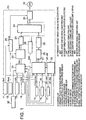
- a speed change control device according to a first embodiment is provided with a controller 10 and a step motor 31 which perform speed change control of a V-belt continuously variable transmission.
- the V-belt continuously variable transmission comprises a primary pulley joined to the engine via a torque converter, a secondary pulley joined to a propeller shaft which rotates the wheels and a V-belt looped around these pulleys as disclosed in the Japanese patent application JP-A-07301297, as well as USP5,178,044, USP 5,313,125.
- a desired speed change ratio is obtained by varying the groove width of these pulleys, the groove width being varied according to the angular position of the step motor 31.
- the controller 10 comprises a microcomputer comprising a central processing unit (CPU), read-only memory (ROM), random access memory (RAM) and input-output interface (I/O interface).
- CPU central processing unit
- ROM read-only memory
- RAM random access memory
- I/O interface input-output interface
- Signals are input to the controller 10 from a primary pulley rotation speed sensor 11 which detects a rotation speed Npri of the primary pulley, a secondary pulley rotation speed sensor 12 which detects a rotation speed Nsec of the secondary pulley, a vehicle speed sensor 13 which detects a vehicle speed VSP , a throttle opening sensor 14 which detects a throttle opening TVO of an engine, an inhibitor switch 15 which detects an automatic operation mode designated by the lever attached to the continuously variable transmission, an M range switch 16 which detects a selection of a manual operation mode of the continuously variable transmission, and a speed change command detection switch 17 which detects a speed change ratio command input value corresponding to a shift-up operation frequency and a shift-down operation frequency in the manual operation mode.
- the speed change ratio command input value in the manual operation mode comprises six speeds from a first speed M1* to a sixth speed M6*.
- one operation of the lever inputs a command to shift-up or shift-down to an adjacent speed change ratio according to the operation direction thereof.
- a shift-down command to the first speed M1 is input by performing three shift-down operations in succession, and then the speed change command detection switch 17 detects a speed change ratio command input value corresponding to the first speed M1.
- the M range switch 16 and speed change command detection switch 17 are both attached to the operating lever of the transmission. The operation of this lever enables the driver to perform the selection of the manual operation mode and shift-up or shift-down in the manual operation mode.
- the automatic operation modes comprise a parking mode P, reverse mode R, neutral mode N, forward ordinary travel mode D and forward high performance travel mode Ds.
- the forward high performance travel mode Ds is a mode which keeps the engine rotation speed higher than the forward ordinary travel mode D.
- the controller 10 calculates a target speed change ratio of the continuously variable transmission, and outputs a corresponding drive signal to the step motor 31.
- the controller 10 comprises an M range speed change ratio determining unit 20, a target primary rotation speed computing unit 21, a final target speed change ratio computing unit 22, a speed change ratio limiter unit 23, a transient target speed change ratio computing unit 24, a real speed change ratio computing unit 25, a target speed change ratio deviation computing unit 26, a time constant computing unit 27, a time constant lower limit limiting unit 28, a time constant variation speed upper limit limiting unit 29 and a motor drive signal computing unit 30.
- the M range speed change ratio determining unit 20 determines speed change ratio command values M1 - M6 in the manual operation mode by a process described hereafter.
- the throttle opening TVO may be replaced by an accelerator depression amount, or by any other parameter which represents the engine load or the intension of acceleration of the driver.
- the target primary rotation speed computing unit 21 performs the following processing according to the manual operation mode detected by the M range switch 16.
- a target primary rotation speed Npri* is calculated by referring to a map of contents shown in Figs. 2A and 2B on the basis of the throttle opening TVO , vehicle speed VSP detected by the vehicle speed sensor 13, and automatic operation mode detected by the inhibitor switch 15.
- the target primary rotation speed Npri* is calculated by referring to a map of contents shown in Fig. 2C based on the speed change ratio command values M1 - M6 determined by the M range speed change ratio determining unit 20 and the vehicle speed VSP .
- This map is also stored beforehand in the ROM of the controller 10.
- the final target speed change ratio computing unit 22 calculates a final target speed change ratio basic value i po ' on the basis of the following equation using the target primary rotation speed Npri* , and the rotation speed Nsec of the secondary pulley detected by the secondary pulley rotation speed sensor 12.
- i po ' Npri * N sec
- the speed change ratio limiter unit 23 sets a smaller limit value and a larger limit value of the final target speed change ratio based on the operating limits of the hardware involved in speed change.
- a final target speed change ratio i po is calculated by limiting this final target speed change ratio basic value i po ' to smaller and larger limits. The value is then output to the transient target speed change ratio computing unit 24. All the values referred to as final target speed change ratio i po in the following description should be understood to mean values subject to this limit as processed with respect to smaller and larger limiting values.
- the time constant computing unit 27 determines the time constant T of speed change control based on the vehicle speed VSP , throttle opening TVO , the selected mode R, N, D or Ds when in the automatic operation mode or the speed change ratio command value M1-M6 when the manual operation mode, and the speed change ratio deviation ei p .
- the time constant T is a constant to show the response characteristics of the transient target speed change ratio i pT relative to the final target speed change ratio i po , and is used when the transient target speed change ratio computing unit 24 determines the transient target speed change ratio i pT from the final target speed change ratio i po . Further, the larger the speed change ratio deviation ei p is, the larger the time constant T .
- the time constant lower limiting unit 28 limits the time constant T set in this way so that it is not less than a preset lower limit, and the time constant variation speed upper limit limiting unit 29 sets an upper limit so that the variation rate of the time constant T does not exceed the preset upper limit.
- a motor drive signal computing unit 30 calculates a step motor drive signal to eliminate this difference based on the difference between the transient target speed change ratio i pT and real speed change ratio i p , and outputs it to the step motor 31.
- a step S51 it is determined whether or not a shift-down has been commanded based on the speed change ratio command input value M1* - M6* detected by the speed change command detection switch 17 and the current real speed change ratio i p .
- the routine proceeds to a step S52, and when a shift-up has been commanded, the process is terminated without executing subsequent steps. Due to this, during a shift-up operation, the input value M1* - M6* detected by the speed change command detection switch 17 is input without modification to the target primary rotation speed computing unit 21 as the command value M1 - M6.
- step S52 it is determined whether or not a shift-down operation is being performed.
- This determination is made by determining whether or not a difference between or ratio of the final target speed change ratio i po and real speed change ratio i p is larger than a predetermined reference value. Immediately after the manual speed change mode is selected, the speed change ratio command value M1 - M6 has not yet been entered in the time constant computing unit 27 and the shift-down operation has not yet started.
- the determination result of the step S52 is negative in this case. This result may also be negative when a shift-down operation has been completed.
- step S52 it is then determined whether or not the engine brake is operating in a step S54.
- This determination is made by determining whether or not the throttle opening TVO is equal to or less than a preset value TVO 0 . In other words, when the throttle opening TVO is equal to or less than the set value TVO 0 , it is determined that the engine brake is operating.
- the current gear CurGp is set one step lower in the step S58, and the process is terminated.
- the initial flag C is 0 in a step S55.
- the initial flag C is initialized to 0 when the manual operation mode starts. Therefore, the initial flag C takes the value 0 the first time the process is performed after the input of a shift-down command or shift-up command.
- the initial flag is 0 in the step S55, it is set to 1 in a step S56. Also, the current gear CurGp is set one step lower in the step S58, and the process is terminated.
- step S55 When the initial flag is not 0 in the step S55, the routine proceeds to a step S57, and the process is terminated maintaining the current gear CurGp .
- the speed change ratio command value M1 - M6 determined in this way is input to the target primary rotation speed computing unit 21 and the time constant computing unit 27.
- the target primary rotation speed computing unit 21 calculates the target primary rotation speed Npri* based on the speed change ratio command value M1 - M6 and vehicle speed VSP as described hereabove.
- the time constant computing unit 27 determines the time constant T when the speed change ratio corresponding to the command value M1 - M6 is realized.
- Subsequent speed change control by the controller 10 is the same as control in the automatic operation mode.
- the speed change ratio command value is determined as follows.
- a shift-down command is detected in the step S51, and the routine proceeds to the step S52.
- the routine proceeds to the step S53, and after resetting the initial flag C to 0, the speed change ratio command value is set from the current fourth speed M4 to the third speed M3, and the process is terminated.
- the controller 10 performs a shift-down to the speed M3.
- the process proceeds from the step S52 to the step S54.
- the speed change ratio command value is changed to the second speed M2 which is the adjacent larger speed change ratio in the step S58.
- the initial flag C is determined in the step S55. As the initial flag C was reset to 0 on the immediately preceding occasion the process was performed, the process proceeds to the step S56.
- step S56 the initial flag C is set to 1, and the speed change command value is changed to the second speed M2 in the step S58 and the process is terminated.
- a speed change is performed from the fourth speed M4 to the second speed M2, but provided that a shift-down operation and the engine brake is operating, the third shift-down input is ignored, and a speed change to the first speed M1 is not performed.
- a shift-down input to the first speed M1 becomes possible only after the speed change ratio corresponding to the second speed M2 is achieved, and it is determined that a shift-down is not being performed in the step S52.
- the change of speed change ratio relative to a continuous shift-down input was limited to two times, however according to this embodiment, a shift-down limit speed change ratio is set according to the speed change ratio before the shift-down operation is started, and speed changes exceeding this shift-down limit speed change ratio are restricted even when shift-down inputs are performed in succession.
- the steps S53, S55 and S56 of the first embodiment are discarded, a new step S101 is provided between the steps S52 and S54, and a new step S102 is provided between the steps S54 and S57.
- the shift-down limit speed change ratio is set in the step S101 depending on the details of the shift-down input as follows. Shift-down input Shift-down limit speed change ratio M6 ⁇ M5 M3 M5 ⁇ M4 M3 M4 ⁇ M3 M2 M3 ⁇ M2 M2 ⁇ M1 M1
- the contents of shift-down input are based on a speed change ratio when it was first determined that a shift-down was commanded in the step S51. For example, when a shift-down is input at the fourth speed M4, a shift-down to the third speed M3 from the fourth speed M4 is commanded regardless of the number of times the operating lever is operated continuously, and, in this case, the shift-down limit speed change ratio is set to the ratio corresponding to the second speed M2.
- the speed change ratio when the determination result of step S51 was affirmative for the first time is stored, and determination of the shift-down limit speed change ratio in the step S101 is performed based on this stored speed change ratio.
- This processing is made possible by, for example, providing steps between the step S51 and step S52 firstly for determining whether or not the determination result of the step S51 is the same as on the immediately preceding occasion, and secondly for storing the current speed change ratio when the determination result is negative.
- the speed change width to the shift-down limit speed change ratio is proportional to the speed change ratio before the shift-down operation is started, i.e., the smaller the speed change ratio before the shift-down operation is started, the larger the speed change width.
- a smaller speed change ratio denotes a higher vehicle speed.
- the reason for this is as follows.
- the engine brake power which acts during a shift-down from third speed to second speed, for example, is larger than the engine brake power which acts during a shift down from sixth speed to fifth speed. Therefore, in order not to let the driver experience an excessive engine braking sensation, shift-down through plural ratios from speed change ratios corresponding to lower speeds must be limited.
- the current gear CurGp is set one step lower in the step S58.
- the change of speed change ratio relative to a continuous shift down input was limited to two, but according to this embodiment, a shift-down to the first speed M1 is prohibited when the second speed M2 is not achieved in the shift-down operation.
- steps S53, S55 and S56 of the first embodiment are discarded, and a new step S201 is provided between the steps S54 and S57.
- step S201 when it is determined that the engine brake is operating in the step S54, it is determined in the step S201 whether or not the current gear CurGp corresponds to the speed M2. When the current gear CurGp does not correspond to the second speed M2, the current gear CurGp is set one step lower in the step S58.
- All of the above embodiments are applied to a continuously variable transmission, but they may be applied to transmissions of all types wherein a manual shift operation is transmitted to a transmission via a controller.
- an acceleration sensor 32 may be provided for detecting a deceleration of the vehicle in the forward/reverse direction, and the engine brake determined to be operating when the absolute value of the deceleration - G detected by the acceleration sensor 32 is equal to or larger than a set threshold value G 0 .
- the determination of whether the engine brake is operating may be performed more precisely by determining that the engine brake is operating only when the throttle opening TVO is equal to or less than the set value TVO o , and the absolute value of the deceleration -G is equal to or larger than the threshold value G 0 .
- the throttle opening sensor 14 and the acceleration sensor 32 in the above description constitute the engine brake condition sensor in Claim 2.
- the primary pulley rotation speed sensor 11 and the secondary pulley rotation speed sensor 12 in the above description constitute the real speed change ratio providing unit in Claim 2.
Abstract
Description
- This invention relates to a speed change controller according to the preamble portion of
claim 1 for use with an automatic transmission of a vehicle in which a manual operation mode is provided. - In an automatic transmission for a vehicle, the speed change ratio is varied automatically according to vehicle speed or throttle opening, etc. Apart from the automatic operation mode, a speed change control device which permits manual operation by a driver is disclosed in the Japanese Patent application JP-A-05322022 published by the Japanese Patent Office in 1993.
- Another similar device corresponding to the preamble of
claim 1 is known from JP-A-05248523. - This device comprises an operating lever for the driver to input a shift-up command or shift-down command into the speed change control device. In manual mode speed change, the automatic transmission performs shift-up or shift-down operations according to the operating direction and operating frequency of the operating lever. That is to say when, for example, the operating lever is moved twice in the shift-down direction from fourth speed, a shift-down to second speed from fourth speed is performed.
- However, when operations of the operating lever are successively performed in the same direction, the speed changes abruptly from fourth speed to first speed in a short time, and as a result the driver experiences an excessive engine braking sensation.
- It is therefore an object of this invention to provide a speed change controller as indicated above adapted to limit manual speed change operations in an automatic transmission comprising a manual mode speed change, such that a driver does not experience an excessive engine braking sensation.
- This objective is solved in an inventive manner by a speed change controller having the features of
claim 1. According to a preferred embodiment there is provided a speed change controller for outputting a speed change ratio command signal to a transmission of a vehicle for selectively applying plural speed change ratios from a largest speed change ratio to a smallest speed change ratio according to a command input by a driver. The vehicle comprises an engine being capable of exerting an engine brake on the vehicle according to a reduction operation input by the driver. - The controller comprises an engine brake sensor for detecting whether or not the vehicle is under the action of the engine brake, a real speed change ratio detection sensor for detecting a real speed change ratio of the transmission, and a microprocessor programmed to determine whether or not the transmission is performing a shift-down operation based on the real speed change ratio and the speed change ratio command signal, determine a shift-down limit speed change ratio based on the speed change ratio before the shift-down operation is performed, and refrain from outputting a speed change ratio command signal corresponding to a speed change ratio larger than the shift-down limit speed change ratio when the vehicle is under the action of the engine brake.
- Further, preferred embodiments are laid down in the dependent claims. In the following the present invention is explained with respect to several embodiments thereof in conjunction with the accompanying drawings, wherein:
- Fig. 1 is a schematic diagram of a speed change control device according a first embodiment,
- Figs. 2A - 2C are diagrams describing characteristics of an automatic transmission to which the teaching of this embodiment is applied according to different operation modes,
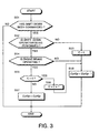
- Fig. 3 is a flowchart describing a process of determining a speed range performed by the speed change control device in the manual operation mode,
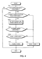
- Fig. 4 is similar to Fig. 3, but showing a second embodiment, and
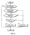
- Fig. 5 is similar to Fig. 3, but showing a third embodiment.
-
- Referring to Fig. 1 of the drawings, a speed change control device according to a first embodiment is provided with a
controller 10 and astep motor 31 which perform speed change control of a V-belt continuously variable transmission. - The V-belt continuously variable transmission comprises a primary pulley joined to the engine via a torque converter, a secondary pulley joined to a propeller shaft which rotates the wheels and a V-belt looped around these pulleys as disclosed in the Japanese patent application JP-A-07301297, as well as USP5,178,044, USP 5,313,125. A desired speed change ratio is obtained by varying the groove width of these pulleys, the groove width being varied according to the angular position of the
step motor 31. - The
controller 10 comprises a microcomputer comprising a central processing unit (CPU), read-only memory (ROM), random access memory (RAM) and input-output interface (I/O interface). - Signals are input to the
controller 10 from a primary pulleyrotation speed sensor 11 which detects a rotation speed Npri of the primary pulley, a secondary pulleyrotation speed sensor 12 which detects a rotation speed Nsec of the secondary pulley, avehicle speed sensor 13 which detects a vehicle speed VSP, athrottle opening sensor 14 which detects a throttle opening TVO of an engine, aninhibitor switch 15 which detects an automatic operation mode designated by the lever attached to the continuously variable transmission, anM range switch 16 which detects a selection of a manual operation mode of the continuously variable transmission, and a speed changecommand detection switch 17 which detects a speed change ratio command input value corresponding to a shift-up operation frequency and a shift-down operation frequency in the manual operation mode. - The speed change ratio command input value in the manual operation mode comprises six speeds from a first speed M1* to a sixth speed M6*.
- In the manual operation mode, one operation of the lever inputs a command to shift-up or shift-down to an adjacent speed change ratio according to the operation direction thereof. For example, at a fourth speed M4, a shift-down command to the first speed M1 is input by performing three shift-down operations in succession, and then the speed change
command detection switch 17 detects a speed change ratio command input value corresponding to the first speed M1. - The
M range switch 16 and speed changecommand detection switch 17 are both attached to the operating lever of the transmission. The operation of this lever enables the driver to perform the selection of the manual operation mode and shift-up or shift-down in the manual operation mode. The automatic operation modes comprise a parking mode P, reverse mode R, neutral mode N, forward ordinary travel mode D and forward high performance travel mode Ds. The forward high performance travel mode Ds is a mode which keeps the engine rotation speed higher than the forward ordinary travel mode D. - Based on these input signals, the
controller 10 calculates a target speed change ratio of the continuously variable transmission, and outputs a corresponding drive signal to thestep motor 31. - Describing the construction of the
controller 10 from a functional viewpoint, as shown in Fig. 1, thecontroller 10 comprises an M range speed changeratio determining unit 20, a target primary rotationspeed computing unit 21, a final target speed changeratio computing unit 22, a speed changeratio limiter unit 23, a transient target speed changeratio computing unit 24, a real speed changeratio computing unit 25, a target speed change ratiodeviation computing unit 26, a timeconstant computing unit 27, a time constant lowerlimit limiting unit 28, a time constant variation speed upperlimit limiting unit 29 and a motor drivesignal computing unit 30. - Based on the throttle opening TVO detected by the
throttle opening sensor 14, and the speed change ratio command input values M1* - M6* detected by the speed changecommand detection switch 17, the M range speed changeratio determining unit 20 determines speed change ratio command values M1 - M6 in the manual operation mode by a process described hereafter. In the calculation of these speed change ratio command values M1 - M6, the throttle opening TVO may be replaced by an accelerator depression amount, or by any other parameter which represents the engine load or the intension of acceleration of the driver. - The target primary rotation
speed computing unit 21 performs the following processing according to the manual operation mode detected by theM range switch 16. In the automatic operation mode, a target primary rotation speed Npri* is calculated by referring to a map of contents shown in Figs. 2A and 2B on the basis of the throttle opening TVO, vehicle speed VSP detected by thevehicle speed sensor 13, and automatic operation mode detected by theinhibitor switch 15. - This map is stored beforehand in the ROM of the
controller 10. On the other hand, in the manual operation mode, the target primary rotation speed Npri* is calculated by referring to a map of contents shown in Fig. 2C based on the speed change ratio command values M1 - M6 determined by the M range speed changeratio determining unit 20 and the vehicle speed VSP. This map is also stored beforehand in the ROM of thecontroller 10. - The final target speed change
ratio computing unit 22 calculates a final target speed change ratio basic value ipo' on the basis of the following equation using the target primary rotation speed Npri*, and the rotation speed Nsec of the secondary pulley detected by the secondary pulleyrotation speed sensor 12. - The speed change
ratio limiter unit 23 sets a smaller limit value and a larger limit value of the final target speed change ratio based on the operating limits of the hardware involved in speed change. A final target speed change ratio ipo is calculated by limiting this final target speed change ratio basic value ipo' to smaller and larger limits. The value is then output to the transient target speed changeratio computing unit 24. All the values referred to as final target speed change ratio ipo in the following description should be understood to mean values subject to this limit as processed with respect to smaller and larger limiting values. - The real speed change
ratio computing unit 25 calculates a real speed change ratio ip by the following equation on the basis of the primary pulley rotation speed Npri detected by the primary pulleyrotation speed sensor 11 and the secondary pulley rotation speed Nsec detected by the secondary pulleyrotation speed sensor 12. - The target speed change ratio
deviation computing unit 26 calculates a difference eip between the final target speed change ratio ipo processed by the speed changeratio limiter unit 23 and the transient target speed change ratio ipT calculated by the transient target speed changeratio computing unit 24 as described hereafter, by the following equation: - The time
constant computing unit 27 determines the time constant T of speed change control based on the vehicle speed VSP, throttle opening TVO, the selected mode R, N, D or Ds when in the automatic operation mode or the speed change ratio command value M1-M6 when the manual operation mode, and the speed change ratio deviation eip . The time constant T is a constant to show the response characteristics of the transient target speed change ratio ipT relative to the final target speed change ratio ipo , and is used when the transient target speed changeratio computing unit 24 determines the transient target speed change ratio ipT from the final target speed change ratio ipo . Further, the larger the speed change ratio deviation eip is, the larger the time constant T. - The time constant lower limiting
unit 28 limits the time constant T set in this way so that it is not less than a preset lower limit, and the time constant variation speed upperlimit limiting unit 29 sets an upper limit so that the variation rate of the time constant T does not exceed the preset upper limit. - Using the time constant T processed in this way, and the final target speed change ratio ipo calculated by the speed change
ratio limiter unit 23, the transient target speed changeratio computing unit 24 calculates the transient target speed change ratio ipT by the following equation: - A motor drive
signal computing unit 30 calculates a step motor drive signal to eliminate this difference based on the difference between the transient target speed change ratio ipT and real speed change ratio ip , and outputs it to thestep motor 31. - Next, the process of determining a speed change ratio in the manual operation mode performed by the M range speed change
ratio determining unit 20 will be described referring to the flowchart of Fig. 3. This process is invoked when the manual operation mode is selected by operating the operating lever, i.e. when a signal is inputted selecting the manual operation mode from theM range switch 16, and repeated at a fixed interval as long as the manual operation mode is selected. When in this mode, the process execution interval is set at a much shorter interval than the time required for speed change in the transmission when in the manual operation mode. - First, in a step S51, it is determined whether or not a shift-down has been commanded based on the speed change ratio command input value M1* - M6* detected by the speed change
command detection switch 17 and the current real speed change ratio ip . - When a shift-down has been commanded, the routine proceeds to a step S52, and when a shift-up has been commanded, the process is terminated without executing subsequent steps. Due to this, during a shift-up operation, the input value M1* - M6* detected by the speed change
command detection switch 17 is input without modification to the target primary rotationspeed computing unit 21 as the command value M1 - M6. - In the step S52, it is determined whether or not a shift-down operation is being performed.
- This determination is made by determining whether or not a difference between or ratio of the final target speed change ratio ipo and real speed change ratio ip is larger than a predetermined reference value. Immediately after the manual speed change mode is selected, the speed change ratio command value M1 - M6 has not yet been entered in the time
constant computing unit 27 and the shift-down operation has not yet started. - As a result, the determination result of the step S52 is negative in this case. This result may also be negative when a shift-down operation has been completed.
- In either of the above cases, after having reset the initial flag C to 0 in the step S53, the current gear CurGp is set one step lower in a step S58, and the process is terminated. It should be noted that a lower gear means a larger speed change ratio.
- On the other hand once it is determined in the step S52 that a shift-down operation is being performed, it is then determined whether or not the engine brake is operating in a step S54. This determination is made by determining whether or not the throttle opening TVO is equal to or less than a preset value TVO0 . In other words, when the throttle opening TVO is equal to or less than the set value TVO0 , it is determined that the engine brake is operating.
- When it is determined that the engine brake is not operating, the current gear CurGp is set one step lower in the step S58, and the process is terminated.
- When it is determined that the engine brake is operating, it is determined whether or not the initial flag C is 0 in a step S55. The initial flag C is initialized to 0 when the manual operation mode starts. Therefore, the initial flag C takes the
value 0 the first time the process is performed after the input of a shift-down command or shift-up command. - If the initial flag is 0 in the step S55, it is set to 1 in a step S56. Also, the current gear CurGp is set one step lower in the step S58, and the process is terminated.
- When the initial flag is not 0 in the step S55, the routine proceeds to a step S57, and the process is terminated maintaining the current gear CurGp.
- The speed change ratio command value M1 - M6 determined in this way is input to the target primary rotation
speed computing unit 21 and the timeconstant computing unit 27. The target primary rotationspeed computing unit 21 calculates the target primary rotation speed Npri* based on the speed change ratio command value M1 - M6 and vehicle speed VSP as described hereabove. The timeconstant computing unit 27 determines the time constant T when the speed change ratio corresponding to the command value M1 - M6 is realized. - Subsequent speed change control by the
controller 10 is the same as control in the automatic operation mode. - As a result of determining the speed change ratio command value by such a process, when, for example, the driver operates the operating lever three times in succession in the shift-down direction in the manual operation mode while the vehicle is traveling at the fourth speed M4, the speed change ratio command value is determined as follows.
- Specifically, a shift-down command is detected in the step S51, and the routine proceeds to the step S52. When the shift-down command is first input, a shift-down operation has not yet been performed so the routine proceeds to the step S53, and after resetting the initial flag C to 0, the speed change ratio command value is set from the current fourth speed M4 to the third speed M3, and the process is terminated. As a result, the
controller 10 performs a shift-down to the speed M3. - On the next occasion the process is executed, as a shift- down is being performed from the fourth speed to the third speed, the process proceeds from the step S52 to the step S54. When the engine brake is not operating in the step S54, the speed change ratio command value is changed to the second speed M2 which is the adjacent larger speed change ratio in the step S58. On the other hand, when the engine brake is operating, the initial flag C is determined in the step S55. As the initial flag C was reset to 0 on the immediately preceding occasion the process was performed, the process proceeds to the step S56.
- In the step S56, the initial flag C is set to 1, and the speed change command value is changed to the second speed M2 in the step S58 and the process is terminated.
- On the subsequent occasion when the process is executed, the initial flag C is not 0, the process proceeds to the step S57 from the step S55, and the process is terminated with the speed change ratio command value being held at the second speed M2.
- Therefore, only two inputs out of three shift-downs are reflected by a speed change ratio command value. A speed change is performed from the fourth speed M4 to the second speed M2, but provided that a shift-down operation and the engine brake is operating, the third shift-down input is ignored, and a speed change to the first speed M1 is not performed. A shift-down input to the first speed M1 becomes possible only after the speed change ratio corresponding to the second speed M2 is achieved, and it is determined that a shift-down is not being performed in the step S52.
- In this way, by limiting shift-down inputs to a maximum of two, the driver is prevented from experiencing an excessive engine brake sensation.
- A second embodiment relating to the limiting algorithm of shift-down operation will now be described referring to Fig. 4.
- In the aforesaid first embodiment, the change of speed change ratio relative to a continuous shift-down input was limited to two times, however according to this embodiment, a shift-down limit speed change ratio is set according to the speed change ratio before the shift-down operation is started, and speed changes exceeding this shift-down limit speed change ratio are restricted even when shift-down inputs are performed in succession.
- For this purpose, the steps S53, S55 and S56 of the first embodiment are discarded, a new step S101 is provided between the steps S52 and S54, and a new step S102 is provided between the steps S54 and S57. In this process, when it is determined that a shift-down operation is being performed in the step S52, the shift-down limit speed change ratio is set in the step S101 depending on the details of the shift-down input as follows.
Shift-down input Shift-down limit
speed change ratioM6 → M5 M3 M5 → M4 M3 M4 → M3 M2 M3 → M2 M2 M2 → M1 M1 - Here, the contents of shift-down input are based on a speed change ratio when it was first determined that a shift-down was commanded in the step S51. For example, when a shift-down is input at the fourth speed M4, a shift-down to the third speed M3 from the fourth speed M4 is commanded regardless of the number of times the operating lever is operated continuously, and, in this case, the shift-down limit speed change ratio is set to the ratio corresponding to the second speed M2.
- To permit such a setting, the speed change ratio when the determination result of step S51 was affirmative for the first time, is stored, and determination of the shift-down limit speed change ratio in the step S101 is performed based on this stored speed change ratio. This processing is made possible by, for example, providing steps between the step S51 and step S52 firstly for determining whether or not the determination result of the step S51 is the same as on the immediately preceding occasion, and secondly for storing the current speed change ratio when the determination result is negative.
- In the above table,the speed change width to the shift-down limit speed change ratio is proportional to the speed change ratio before the shift-down operation is started, i.e., the smaller the speed change ratio before the shift-down operation is started, the larger the speed change width. Herein a smaller speed change ratio denotes a higher vehicle speed. The reason for this is as follows. The engine brake power which acts during a shift-down from third speed to second speed, for example, is larger than the engine brake power which acts during a shift down from sixth speed to fifth speed. Therefore, in order not to let the driver experience an excessive engine braking sensation, shift-down through plural ratios from speed change ratios corresponding to lower speeds must be limited.
- After having set the shift-down limit speed change ratio in this way, it is determined whether or not the engine brake is operating in the step S54, and if the engine brake is operating, it is determined whether or not the current speed change ratio is equal to the shift-down limit speed change ratio in the step S102.
- When a shift-down operation is not being performed in the step S52, the engine brake is not being operated in the step S54 or the current speed change ratio is not equal to the shift-down limit speed change ratio in the step S102, there is no risk that the driver will experience an excessive engine braking sensation even if a shift-down is performed. In this case, the current gear CurGp is set one step lower in the step S58.
- On the other hand when it is determined that the current speed change ratio is equal to the shift-down limit speed change ratio in the step S102, the current gear CurGp is maintained in the step S57 and the process is terminated.
- By executing the above process repeatedly, when for example, the driver operates the operating lever three times in succession in the shift-down direction during travel at the fourth speed M4, i.e. when a speed change from the fourth speed M4 to the first speed M1 was commanded, a real speed change operation is performed only from the fourth speed M4 to the second speed M2. To perform a shift-down to the first speed M1 after shift down to the second speed M2 was completed, the operating lever must be operated again to perform another shift-down input. The same effect is therefore obtained in this embodiment as in the aforesaid first embodiment.
- Next, referring to Fig. 5, a third embodiment relating to the limiting algorithm of the shift-down operation will be described.
- In the aforesaid first embodiment, the change of speed change ratio relative to a continuous shift down input was limited to two, but according to this embodiment, a shift-down to the first speed M1 is prohibited when the second speed M2 is not achieved in the shift-down operation.
- For this purpose, the steps S53, S55 and S56 of the first embodiment are discarded, and a new step S201 is provided between the steps S54 and S57.
- In this process, when it is determined that the engine brake is operating in the step S54, it is determined in the step S201 whether or not the current gear CurGp corresponds to the speed M2. When the current gear CurGp does not correspond to the second speed M2, the current gear CurGp is set one step lower in the step S58.
- On the other hand when the current gear CurGp corresponds to the second speed M2, the current gear CurGp is maintained in the step S57 and the process is terminated.
- In this embodiment, when speed change to the second speed M2 is not complete, a shift-down input to the first speed M1 is not accepted. The same effect is therefore obtained as in the aforesaid first embodiment.
- All of the above embodiments are applied to a continuously variable transmission, but they may be applied to transmissions of all types wherein a manual shift operation is transmitted to a transmission via a controller.
- Also, instead of comparing the throttle opening TVO with the set value TVO0 as a method of determining whether or not the engine brake is operating in the step S54, an
acceleration sensor 32 may be provided for detecting a deceleration of the vehicle in the forward/reverse direction, and the engine brake determined to be operating when the absolute value of the deceleration -G detected by theacceleration sensor 32 is equal to or larger than a set threshold value G0 . - Further, the determination of whether the engine brake is operating may be performed more precisely by determining that the engine brake is operating only when the throttle opening TVO is equal to or less than the set value TVOo , and the absolute value of the deceleration -G is equal to or larger than the threshold value G0 .
- It should also be noted that, in the description hereabove, the smallest speed change ratio corresponds to the highest speed and the largest speed change ratio corresponds to the lowest speed. Therefore, shift-down denotes a change-over of speed change ratio to a larger one while shift-up denotes change over of the same to a smaller one.
- The
throttle opening sensor 14 and theacceleration sensor 32 in the above description constitute the engine brake condition sensor in Claim 2. - The primary pulley
rotation speed sensor 11 and the secondary pulleyrotation speed sensor 12 in the above description constitute the real speed change ratio providing unit in Claim 2.
Claims (8)
- A speed change controller for outputting a speed change ratio command signal to a transmission of a vehicle for selectively applying plural speed change ratios from a largest speed change ratio to a smallest speed change ratio according to a command input by a driver, the vehicle comprising an engine being capable of exerting an engine brake on the vehicle according to a reduction operation input by the driver, characterized in that the controller comprises:engine braking sensing means (14, 32) for detecting whether or not the vehicle is under the action of the engine brake;real speed change ratio indicating means (11, 12) for providing a real speed change ratio of the transmission;first means (10, S52) determining whether or not the transmission is performing a shift-down operation based on the real speed change ratio and the speed change ratio command signal;second means (10, S101) determining a shift-down limit speed change ratio based on the speed change ratio before the shift-down operation is performed; andthird means (10, S102, S57) refraining from outputting a speed change ratio command signal corresponding to a speed change ratio larger than the shift-down limit speed change ratio, when the vehicle is under the action of the engine brake.
- The speed change controller according to claim 1, characterized in that the engine braking sensing means (14, 32) comprises an engine brake condition sensor (14, 32) which detects whether or not the vehicle is under the action of the engine brake, the real speed change ratio indicating means (11, 12) comprises a real speed change ratio providing unit (11, 12) which provides a real speed change ratio of the transmission, and the first means (10, S52), the second means (10, S101) and the third means (10, S102, S57) comprise a microprocessor (10) programmed to:determine whether or not the transmission is performing a shift-down operation based on the real speed change ratio and the speed change ratio command signal (S52);determine a shift-down limit speed change ratio based on the speed change ratio before the shift-down operation is performed (S101); andrefrain from outputting a speed change ratio command signal corresponding to a speed change ratio larger than the shift-down limit speed change ratio, when the vehicle is under the action of the engine brake (S102, S57).
- The speed change controller according to claim 2, characterized in that the microprocessor (10) is further programmed to determine the shift-down limit speed change ratio such that the larger the speed change ratio before the shift-down operation is performed, the smaller the difference between the shift-down limit speed change ratio and the speed change ratio before the shift-down operation is performed (S101).
- The speed change controller according to claim 2, characterized in that the microprocessor (10) is further programmed to determine the shift-down limit speed change ratio such that a difference between the shift-down limit speed change ratio and the speed change ratio before the shift-down operation is performed is equivalent to a difference corresponding to two consecutive shift-down operations (S53, S55 - S58).
- The speed change controller according to one of the claims 2 to 4, characterized in that the microprocessor (10) is further programmed to determine the shift-down limit speed change ratio equal to a second largest speed change ratio among the plural speed change ratios (S201, S57).
- The speed change controller according to one of the claims 2 to 5, characterized in that the engine comprises a throttle for increasing and decreasing output, and the engine brake condition sensor (14, 32) comprises a throttle opening sensor (14) for detecting that an opening of the throttle is equal to or less than a predetermined threshold value.
- The speed change controller according to one of the claims 2 to 5, characterized in that the engine brake condition sensor (14, 32) comprises a deceleration sensor (32) for detecting that a deceleration of the vehicle in the forward/reverse direction surpasses a predetermined threshold value.
- The speed change controller according to one of the claims 2 to 5, characterized in that the engine comprises a throttle for increasing/decreasing output, the engine brake condition sensor (14, 32) comprises a throttle opening sensor (14) for detecting that an opening of the throttle is equal to or less than a predetermined first threshold value and a deceleration sensor (32) for detecting that a deceleration of the vehicle in the forward/reverse direction surpasses a predetermined second threshold value, and the microprocessor (10) is further programmed to determine that the vehicle is under the action of the engine brake when the throttle opening is equal to or less than the first threshold value, and the deceleration of the vehicle in the forward/reverse direction surpasses the second threshold value.
Applications Claiming Priority (9)
| Application Number | Priority Date | Filing Date | Title |
|---|---|---|---|
| JP186614/97 | 1997-07-11 | ||
| JP18661497A JP3627456B2 (en) | 1997-07-11 | 1997-07-11 | Shift control device for automatic transmission |
| JP18661497 | 1997-07-11 | ||
| JP19693297 | 1997-07-23 | ||
| JP196931/97 | 1997-07-23 | ||
| JP19693197A JP3624639B2 (en) | 1997-07-23 | 1997-07-23 | Shift control device for automatic transmission |
| JP19693297A JP3624640B2 (en) | 1997-07-23 | 1997-07-23 | Shift control device for automatic transmission |
| JP19693197 | 1997-07-23 | ||
| JP196932/97 | 1997-07-23 |
Publications (3)
| Publication Number | Publication Date |
|---|---|
| EP0890764A2 EP0890764A2 (en) | 1999-01-13 |
| EP0890764A3 EP0890764A3 (en) | 2000-11-22 |
| EP0890764B1 true EP0890764B1 (en) | 2003-10-01 |
Family
ID=27325776
Family Applications (1)
| Application Number | Title | Priority Date | Filing Date |
|---|---|---|---|
| EP98112791A Expired - Lifetime EP0890764B1 (en) | 1997-07-11 | 1998-07-09 | Speed change controller for automatic transmission |
Country Status (3)
| Country | Link |
|---|---|
| US (1) | US6246940B1 (en) |
| EP (1) | EP0890764B1 (en) |
| DE (1) | DE69818563T2 (en) |
Cited By (1)
| Publication number | Priority date | Publication date | Assignee | Title |
|---|---|---|---|---|
| US8047960B2 (en) | 2006-10-13 | 2011-11-01 | Yamaha Hatsudoki Kabushiki Kaisha | Continuously variable transmission and straddle type vehicle |
Families Citing this family (14)
| Publication number | Priority date | Publication date | Assignee | Title |
|---|---|---|---|---|
| JP4291555B2 (en) | 2002-09-20 | 2009-07-08 | ジヤトコ株式会社 | Shift control device for continuously variable transmission |
| US7287620B2 (en) * | 2004-07-13 | 2007-10-30 | Caterpillar S.A.R.L. | Method and apparatus for controlling the speed ranges of a machine |
| US7637845B2 (en) | 2005-10-11 | 2009-12-29 | Caterpillar Inc. | System and method for controlling vehicle speed |
| US7544148B2 (en) * | 2005-12-27 | 2009-06-09 | Caterpillar Inc. | System and method for controlling vehicle speed |
| JP5209258B2 (en) * | 2006-10-27 | 2013-06-12 | ヤマハ発動機株式会社 | Saddle riding vehicle |
| CN101529131B (en) * | 2006-11-30 | 2012-11-14 | 日立建机株式会社 | Speed change control system for industrial vehicle |
| US8380408B2 (en) * | 2006-11-30 | 2013-02-19 | Hitachi Construction Machinery Co., Ltd. | Speed change control system for industrial vehicle |
| US7641588B2 (en) * | 2007-01-31 | 2010-01-05 | Caterpillar Inc. | CVT system having discrete selectable speed ranges |
| US7957873B2 (en) * | 2007-03-09 | 2011-06-07 | GM Global Technology Operations LLC | Vehicle transmission shift inhibit method and apparatus |
| EP2202430B1 (en) * | 2007-10-22 | 2012-05-30 | Komatsu Ltd. | Transmission control device and method for working vehicle |
| US8321105B2 (en) | 2007-10-31 | 2012-11-27 | Caterpillar Inc. | Propulsion system with a continuously variable transmission |
| JP4678403B2 (en) * | 2007-12-19 | 2011-04-27 | トヨタ自動車株式会社 | Control device for automatic transmission, control method, program for realizing the method, and recording medium recording the program |
| US8795133B2 (en) * | 2012-11-01 | 2014-08-05 | Caterpillar Inc. | Event-based retarding in a machine with a continuously variable transmission |
| CN104315135B (en) * | 2014-09-15 | 2017-01-25 | 山东理工大学 | Variable-cycle upshift process control method for multi-gear wire control automatic transmission |
Family Cites Families (10)
| Publication number | Priority date | Publication date | Assignee | Title |
|---|---|---|---|---|
| JPH07456B2 (en) * | 1986-09-19 | 1995-01-11 | 日産自動車株式会社 | Shift control device for continuously variable transmission |
| JPH0454362A (en) | 1990-06-21 | 1992-02-21 | Nissan Motor Co Ltd | Speed change controller for continuously variable transmission |
| US5247216A (en) | 1991-12-30 | 1993-09-21 | North American Philips Corporation | Stepper motor with integrated assembly |
| JPH05248523A (en) | 1992-03-03 | 1993-09-24 | Toyota Motor Corp | Speed change controller of automatic transmission |
| JP3078651B2 (en) | 1992-05-20 | 2000-08-21 | トヨタ自動車株式会社 | Transmission control device for automatic transmission |
| JP3058005B2 (en) | 1994-04-28 | 2000-07-04 | 日産自動車株式会社 | Control device for continuously variable transmission |
| JP3087001B2 (en) * | 1994-09-05 | 2000-09-11 | 株式会社ユニシアジェックス | Control device for continuously variable transmission |
| JP3358419B2 (en) * | 1996-01-31 | 2002-12-16 | 日産自動車株式会社 | Transmission control device for continuously variable automatic transmission |
| JP3475639B2 (en) * | 1996-03-07 | 2003-12-08 | 日産自動車株式会社 | Transmission control device for continuously variable transmission |
| JP3358435B2 (en) * | 1996-04-12 | 2002-12-16 | 日産自動車株式会社 | Transmission control device for continuously variable automatic transmission |
-
1998
- 1998-07-07 US US09/111,594 patent/US6246940B1/en not_active Expired - Fee Related
- 1998-07-09 DE DE69818563T patent/DE69818563T2/en not_active Expired - Fee Related
- 1998-07-09 EP EP98112791A patent/EP0890764B1/en not_active Expired - Lifetime
Cited By (1)
| Publication number | Priority date | Publication date | Assignee | Title |
|---|---|---|---|---|
| US8047960B2 (en) | 2006-10-13 | 2011-11-01 | Yamaha Hatsudoki Kabushiki Kaisha | Continuously variable transmission and straddle type vehicle |
Also Published As
| Publication number | Publication date |
|---|---|
| US6246940B1 (en) | 2001-06-12 |
| DE69818563T2 (en) | 2004-04-29 |
| DE69818563D1 (en) | 2003-11-06 |
| EP0890764A3 (en) | 2000-11-22 |
| EP0890764A2 (en) | 1999-01-13 |
Similar Documents
| Publication | Publication Date | Title |
|---|---|---|
| EP0890764B1 (en) | Speed change controller for automatic transmission | |
| EP2372195B1 (en) | Shift control device for continuously variable transmission | |
| US5890991A (en) | Control system and method of continuously variable transmission | |
| US6148257A (en) | Vehicle drive force controller | |
| EP1340929B1 (en) | Shift controlling apparatus for continuously variable transmission | |
| EP0889264B1 (en) | Speed change ratio controller for continuously variable transmission | |
| JP3459290B2 (en) | Control device for vehicles with continuously variable transmission | |
| US5161433A (en) | Apparatus for controlling a continuously variable transmission | |
| EP1177934A2 (en) | Shift control system for continuously variable transmission | |
| US6640179B2 (en) | Vehicle drive force control | |
| EP0965775B1 (en) | Speed controller and control method of continuously variable transmission | |
| JPH09196165A (en) | Speed change control device of continuously variable transmission | |
| US5172610A (en) | Stepless-speed-changer engine brake controller | |
| JP2875316B2 (en) | Control device for continuously variable transmission for vehicles | |
| JP3423840B2 (en) | Control device for continuously variable transmission | |
| JP3425841B2 (en) | Control device for continuously variable transmission | |
| JP3240961B2 (en) | Transmission control device for continuously variable transmission | |
| KR100384646B1 (en) | Controller for vehicle interior devices | |
| JP3624639B2 (en) | Shift control device for automatic transmission | |
| JP3624640B2 (en) | Shift control device for automatic transmission | |
| JP3627456B2 (en) | Shift control device for automatic transmission | |
| JP3436027B2 (en) | Transmission control device for continuously variable transmission | |
| JP3475631B2 (en) | Transmission control device for belt-type continuously variable transmission | |
| JP3168787B2 (en) | Automatic transmission for vehicles | |
| JP4461823B2 (en) | Shift control device for continuously variable transmission |
Legal Events
| Date | Code | Title | Description |
|---|---|---|---|
| PUAI | Public reference made under article 153(3) epc to a published international application that has entered the european phase |
Free format text: ORIGINAL CODE: 0009012 |
|
| 17P | Request for examination filed |
Effective date: 19980709 |
|
| AK | Designated contracting states |
Kind code of ref document: A2 Designated state(s): DE FR GB |
|
| AX | Request for extension of the european patent |
Free format text: AL;LT;LV;MK;RO;SI |
|
| PUAL | Search report despatched |
Free format text: ORIGINAL CODE: 0009013 |
|
| AK | Designated contracting states |
Kind code of ref document: A3 Designated state(s): AT BE CH CY DE DK ES FI FR GB GR IE IT LI LU MC NL PT SE |
|
| AX | Request for extension of the european patent |
Free format text: AL;LT;LV;MK;RO;SI |
|
| AKX | Designation fees paid |
Free format text: DE FR GB |
|
| 17Q | First examination report despatched |
Effective date: 20020904 |
|
| GRAH | Despatch of communication of intention to grant a patent |
Free format text: ORIGINAL CODE: EPIDOS IGRA |
|
| GRAS | Grant fee paid |
Free format text: ORIGINAL CODE: EPIDOSNIGR3 |
|
| GRAA | (expected) grant |
Free format text: ORIGINAL CODE: 0009210 |
|
| AK | Designated contracting states |
Kind code of ref document: B1 Designated state(s): DE FR GB |
|
| REG | Reference to a national code |
Ref country code: GB Ref legal event code: FG4D |
|
| REF | Corresponds to: |
Ref document number: 69818563 Country of ref document: DE Date of ref document: 20031106 Kind code of ref document: P |
|
| ET | Fr: translation filed | ||
| PLBE | No opposition filed within time limit |
Free format text: ORIGINAL CODE: 0009261 |
|
| STAA | Information on the status of an ep patent application or granted ep patent |
Free format text: STATUS: NO OPPOSITION FILED WITHIN TIME LIMIT |
|
| 26N | No opposition filed |
Effective date: 20040702 |
|
| PGFP | Annual fee paid to national office [announced via postgrant information from national office to epo] |
Ref country code: FR Payment date: 20090710 Year of fee payment: 12 |
|
| PGFP | Annual fee paid to national office [announced via postgrant information from national office to epo] |
Ref country code: GB Payment date: 20090708 Year of fee payment: 12 Ref country code: DE Payment date: 20090702 Year of fee payment: 12 |
|
| GBPC | Gb: european patent ceased through non-payment of renewal fee |
Effective date: 20100709 |
|
| REG | Reference to a national code |
Ref country code: FR Ref legal event code: ST Effective date: 20110331 |
|
| PG25 | Lapsed in a contracting state [announced via postgrant information from national office to epo] |
Ref country code: DE Free format text: LAPSE BECAUSE OF NON-PAYMENT OF DUE FEES Effective date: 20110201 |
|
| REG | Reference to a national code |
Ref country code: DE Ref legal event code: R119 Ref document number: 69818563 Country of ref document: DE Effective date: 20110201 |
|
| PG25 | Lapsed in a contracting state [announced via postgrant information from national office to epo] |
Ref country code: FR Free format text: LAPSE BECAUSE OF NON-PAYMENT OF DUE FEES Effective date: 20100802 |
|
| PG25 | Lapsed in a contracting state [announced via postgrant information from national office to epo] |
Ref country code: GB Free format text: LAPSE BECAUSE OF NON-PAYMENT OF DUE FEES Effective date: 20100709 |