EP1743699A1 - Cartridge and system for conducting a chemical reaction - Google Patents
Cartridge and system for conducting a chemical reaction Download PDFInfo
- Publication number
- EP1743699A1 EP1743699A1 EP06014762A EP06014762A EP1743699A1 EP 1743699 A1 EP1743699 A1 EP 1743699A1 EP 06014762 A EP06014762 A EP 06014762A EP 06014762 A EP06014762 A EP 06014762A EP 1743699 A1 EP1743699 A1 EP 1743699A1
- Authority
- EP
- European Patent Office
- Prior art keywords
- cartridge
- chemical reaction
- well
- passages
- external force
- Prior art date
- Legal status (The legal status is an assumption and is not a legal conclusion. Google has not performed a legal analysis and makes no representation as to the accuracy of the status listed.)
- Withdrawn
Links
Images


Classifications
-
- B—PERFORMING OPERATIONS; TRANSPORTING
- B01—PHYSICAL OR CHEMICAL PROCESSES OR APPARATUS IN GENERAL
- B01L—CHEMICAL OR PHYSICAL LABORATORY APPARATUS FOR GENERAL USE
- B01L3/00—Containers or dishes for laboratory use, e.g. laboratory glassware; Droppers
- B01L3/50—Containers for the purpose of retaining a material to be analysed, e.g. test tubes
- B01L3/502—Containers for the purpose of retaining a material to be analysed, e.g. test tubes with fluid transport, e.g. in multi-compartment structures
- B01L3/5027—Containers for the purpose of retaining a material to be analysed, e.g. test tubes with fluid transport, e.g. in multi-compartment structures by integrated microfluidic structures, i.e. dimensions of channels and chambers are such that surface tension forces are important, e.g. lab-on-a-chip
-
- B—PERFORMING OPERATIONS; TRANSPORTING
- B01—PHYSICAL OR CHEMICAL PROCESSES OR APPARATUS IN GENERAL
- B01L—CHEMICAL OR PHYSICAL LABORATORY APPARATUS FOR GENERAL USE
- B01L2300/00—Additional constructional details
- B01L2300/08—Geometry, shape and general structure
- B01L2300/0861—Configuration of multiple channels and/or chambers in a single devices
-
- B—PERFORMING OPERATIONS; TRANSPORTING
- B01—PHYSICAL OR CHEMICAL PROCESSES OR APPARATUS IN GENERAL
- B01L—CHEMICAL OR PHYSICAL LABORATORY APPARATUS FOR GENERAL USE
- B01L2400/00—Moving or stopping fluids
- B01L2400/04—Moving fluids with specific forces or mechanical means
- B01L2400/0475—Moving fluids with specific forces or mechanical means specific mechanical means and fluid pressure
- B01L2400/0481—Moving fluids with specific forces or mechanical means specific mechanical means and fluid pressure squeezing of channels or chambers
-
- B—PERFORMING OPERATIONS; TRANSPORTING
- B01—PHYSICAL OR CHEMICAL PROCESSES OR APPARATUS IN GENERAL
- B01L—CHEMICAL OR PHYSICAL LABORATORY APPARATUS FOR GENERAL USE
- B01L2400/00—Moving or stopping fluids
- B01L2400/06—Valves, specific forms thereof
- B01L2400/0633—Valves, specific forms thereof with moving parts
-
- B—PERFORMING OPERATIONS; TRANSPORTING
- B01—PHYSICAL OR CHEMICAL PROCESSES OR APPARATUS IN GENERAL
- B01L—CHEMICAL OR PHYSICAL LABORATORY APPARATUS FOR GENERAL USE
- B01L2400/00—Moving or stopping fluids
- B01L2400/06—Valves, specific forms thereof
- B01L2400/0633—Valves, specific forms thereof with moving parts
- B01L2400/0655—Valves, specific forms thereof with moving parts pinch valves
-
- B—PERFORMING OPERATIONS; TRANSPORTING
- B01—PHYSICAL OR CHEMICAL PROCESSES OR APPARATUS IN GENERAL
- B01L—CHEMICAL OR PHYSICAL LABORATORY APPARATUS FOR GENERAL USE
- B01L3/00—Containers or dishes for laboratory use, e.g. laboratory glassware; Droppers
- B01L3/50—Containers for the purpose of retaining a material to be analysed, e.g. test tubes
- B01L3/502—Containers for the purpose of retaining a material to be analysed, e.g. test tubes with fluid transport, e.g. in multi-compartment structures
- B01L3/5027—Containers for the purpose of retaining a material to be analysed, e.g. test tubes with fluid transport, e.g. in multi-compartment structures by integrated microfluidic structures, i.e. dimensions of channels and chambers are such that surface tension forces are important, e.g. lab-on-a-chip
- B01L3/50273—Containers for the purpose of retaining a material to be analysed, e.g. test tubes with fluid transport, e.g. in multi-compartment structures by integrated microfluidic structures, i.e. dimensions of channels and chambers are such that surface tension forces are important, e.g. lab-on-a-chip characterised by the means or forces applied to move the fluids
-
- B—PERFORMING OPERATIONS; TRANSPORTING
- B01—PHYSICAL OR CHEMICAL PROCESSES OR APPARATUS IN GENERAL
- B01L—CHEMICAL OR PHYSICAL LABORATORY APPARATUS FOR GENERAL USE
- B01L3/00—Containers or dishes for laboratory use, e.g. laboratory glassware; Droppers
- B01L3/50—Containers for the purpose of retaining a material to be analysed, e.g. test tubes
- B01L3/502—Containers for the purpose of retaining a material to be analysed, e.g. test tubes with fluid transport, e.g. in multi-compartment structures
- B01L3/5027—Containers for the purpose of retaining a material to be analysed, e.g. test tubes with fluid transport, e.g. in multi-compartment structures by integrated microfluidic structures, i.e. dimensions of channels and chambers are such that surface tension forces are important, e.g. lab-on-a-chip
- B01L3/502738—Containers for the purpose of retaining a material to be analysed, e.g. test tubes with fluid transport, e.g. in multi-compartment structures by integrated microfluidic structures, i.e. dimensions of channels and chambers are such that surface tension forces are important, e.g. lab-on-a-chip characterised by integrated valves
-
- Y—GENERAL TAGGING OF NEW TECHNOLOGICAL DEVELOPMENTS; GENERAL TAGGING OF CROSS-SECTIONAL TECHNOLOGIES SPANNING OVER SEVERAL SECTIONS OF THE IPC; TECHNICAL SUBJECTS COVERED BY FORMER USPC CROSS-REFERENCE ART COLLECTIONS [XRACs] AND DIGESTS
- Y10—TECHNICAL SUBJECTS COVERED BY FORMER USPC
- Y10T—TECHNICAL SUBJECTS COVERED BY FORMER US CLASSIFICATION
- Y10T436/00—Chemistry: analytical and immunological testing
- Y10T436/25—Chemistry: analytical and immunological testing including sample preparation
- Y10T436/2575—Volumetric liquid transfer
Definitions
- the present invention has been made in view of the above circumstances, and provides a cartridge for a chemical reaction and a chemical reaction processing system in which generalized and various processes can be carried out by feeding the liquid in accordance with a deformation when the external force is applied on the cartridge.
- the cartridge of the invention may further comprise: an introducing passage for introducing a sample into the inner part of the cartridge from an outside of the cartridge.
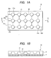
- Fig. 1A is a plan view showing a cartridge for a chemical reaction of the preferred embodiment
- Fig. 1B is a sectional view taken along a line Ib-Ib of Fig. 1A.
- the chemical reaction processing system 50 includes a plurality of actuators 51, another plurality of actuators 53, a plurality of driving circuits 52 for independently driving the plurality of actuators 51 respectively, a plurality of driving circuits 54 for independently driving the other plurality of actuators 53 respectively, a control section 55 for controlling driving circuits 52 and driving circuits 54, and a storing section 56 for storing a program or data.
- Figs.5A-5D show example operations using the cartridge 10.
Landscapes
- Chemical & Material Sciences (AREA)
- Health & Medical Sciences (AREA)
- Dispersion Chemistry (AREA)
- Analytical Chemistry (AREA)
- General Health & Medical Sciences (AREA)
- Hematology (AREA)
- Clinical Laboratory Science (AREA)
- Chemical Kinetics & Catalysis (AREA)
- Physical Or Chemical Processes And Apparatus (AREA)
- Automatic Analysis And Handling Materials Therefor (AREA)
- Feeding, Discharge, Calcimining, Fusing, And Gas-Generation Devices (AREA)
Abstract
Description
- This application claims foreign priority based on
Japanese Patent Application No. 2005-206353, filed July 15, 2005 - The present invention relates to a cartridge for a chemical reaction that generates a chemical reaction by feeding liquid in an inner part in accordance with a deformation caused by an external force, and a chemical reaction processing system for handling the cartridge for a chemical reaction.
- A cartridge for a chemical reaction that generates a chemical reaction by feeding liquid in an inner part in accordance with a deformation when an external force is applied on the cartridge is known (refer to
JP-A-2005-37368 Japanese Patent No.3166144 - In the above-described general-purpose experimental system, the liquid droplets are moved in accordance with a prescribed procedure so that a desired experiment can be carried out. However, since the liquid droplets are exposed to outside air while being on the wafer, the evaporation of the liquid droplets cannot be avoided. Further, there is a problem that various kinds of processes are difficult, such as mixing a plurality of kinds of liquid droplets, heating the liquid droplets, or applying pressure to the liquid droplets.
- The present invention has been made in view of the above circumstances, and provides a cartridge for a chemical reaction and a chemical reaction processing system in which generalized and various processes can be carried out by feeding the liquid in accordance with a deformation when the external force is applied on the cartridge.
- In some implementations, a cartridge of the invention which causes a chemical reaction by feeding liquid in an inner part of the cartridge by deformation when an external force is applied, the cartridge comprising:
- a substrate;
- an elastic member which is overlaid on the substrate;
- a plurality of passages which are provided by said elastic member, wherein
- a plurality of passages are connected with each other in the inner part of the cartridge, and the passages are switched between an opened state and a closed state respectively by the external force.
- According to the cartridge for a chemical reaction, since the plurality of passages are connected with each other in the inner part of the cartridge and the passages are switched between an opened state and a closed state respectively by the external force, the cartridge can be applied to various purposes.
- The cartridge may further comprise a plurality of junctions, each of said junctions connecting at least two of the plurality of passages.
- The cartridge may further comprise a well provided at each junction.
- In the cartridge of the invention, when the external force is applied on the well, the liquid in the well is fed by being pushed out of the well through the passages connected to the well.
- The cartridge of the inventionmay further comprise: an introducing passage for introducing a sample into the inner part of the cartridge from an outside of the cartridge.
- The cartridge of the invention may further comprise: a discharge passage for discharging the liquid to an outside of the cartridge by the external force.
- In some implementations, a chemical reaction processing system of the invention which handles a cartridge for a chemical reaction comprises:
- a first actuator for applying a first external force to the cartridge so as to switch a plurality of passages formed in an inner part of the cartridge between an opened state and a closed state respectively,
- wherein the passages are connected with each other in the inner part of the cartridge, and
- the chemical reaction is caused in the cartridge by feeding liquid in the inner part of the cartridge by deformation when an external force including the first external force is applied.
- According to the chemical reaction processing system, since the actuators are provided for applying the external force to the cartridge to switch the opened and closed states of the individual passages, the cartridge can be applied to various purposes.
- In the chemical reaction processing system of the invention, the cartridge includes a plurality of junctions, each of said junctions connecting at least two of the plurality of passages.
- In the chemical reaction processing system of the invention,
the cartridge includes a well at each junction, and
the chemical reaction processing system further comprising: - a second actuator for applying a second external force as the external force to the cartridge so that the liquid in the well is fed by being pushed out of the well through the passages connected to the well.
- The chemical reaction processing system of the invention further comprises:
- a storing section for storing operation procedures of the first actuator and the second actuator; and
- an actuator control section for operating the first actuator and the second actuator in accordance with the stored operation procedures.
- In this case, since the actuators are operated in accordance with the stored operation procedure, the actuators can be easily operated even if the procedure is complicated.
- The chemical reaction processing system of the invention further comprises:
- a detecting section for detecting a state of the cartridge; and
- a state control section for controlling the state of the cartridge in accordance with a result of the detection by the detecting section.
- According to the cartridge of the invention for a chemical reaction, since the plurality of passages are connected with each other in the inner part of the cartridge and the passages are switched between an opened state and a closed state respectively by the external force, the cartridge can be applied to various purposes.
- According to the chemical reaction processing system of the present invention, since the actuators are provided for applying the external force to the cartridge to switch the opened and closed states of the individual passages, the cartridge can be applied to various purposes.
-
- Fig. 1A is a diagram showing the structure of a cartridge for a chemical reaction of an embodiment, and a plan view showing the cartridge.
- Fig. 1B is a diagram showing the structure of a cartridge for a chemical reaction of an embodiment, and a sectional view taken along the line Ib-Ib of Fig. 1A.
- Fig. 2 is a block diagram showing a structure of a chemical reaction processing system.
- Fig. 3A is a diagram showing the arrangement of control members driven by actuators.
- Fig. 3B is a diagram showing the arrangement of control members driven by actuators, and shows the positional relationship between the cartridge and the control members.
- Figs. 4A to 4C are sectional views of the cartridge showing functions of control members.
- Figs. 5A to 5D show examples of procedures of operations using the cartridge.
- Fig. 6 is a diagram showing a structure for opening and closing a passage by a slide member.
- Now, an embodiment of a cartridge for a chemical reaction according to the present invention will be described below by referring to Figs. 1A to 6.
- Fig. 1A is a plan view showing a cartridge for a chemical reaction of the preferred embodiment, and Fig. 1B is a sectional view taken along a line Ib-Ib of Fig. 1A.
- As shown in Figs. 1A and 1B, a
cartridge 10 for a chemical reaction of the preferred embodiment includes a substrate 1 and anelastic member 2 overlaid on the substrate 1. - On the back surface of the elastic member 2 (the bottom side in Fig. 1B), recessed parts of prescribed shapes are formed that are recessed towards the front surface side (the top side in Fig. 1B). The recessed parts form spaces between the cartridge substrate 1 and the
elastic member 2 to formwells 21 arranged in the form of a matrix andpassages 22 for connecting theadjacent wells 21 together. - In the area excluding the recessed parts, the substrate 1 is bonded to the
elastic member 2. Accordingly, solution contained in the recessed parts can be sealed in the cartridge to prevent the solution from leaking outside. Further, there is no fear that the solution in the cartridge will evaporate. - A
passage 22a connected to awell 21a communicates with an external part through a side surface of thecartridge 10, and functions as an introducing passage for introducing a sample to thewell 21a.Passage 22b which is connected towell 21b andpassage 22c which is connected to well 21c likewise communicate with external parts and serve as introducing passages. - Further,
passage 22d which is connected towell 21d communicates with an external part through a side surface ofcartridge 10 to function as a discharge passage for discharging the solution inwell 21d. - Fig. 2 is a block diagram showing the structure of a chemical
reaction processing system 50 used by combining the system with thecartridge 10. - As shown in Fig. 2, the chemical
reaction processing system 50 includes a plurality ofactuators 51, another plurality ofactuators 53, a plurality of drivingcircuits 52 for independently driving the plurality ofactuators 51 respectively, a plurality of drivingcircuits 54 for independently driving the other plurality ofactuators 53 respectively, acontrol section 55 for controlling drivingcircuits 52 and drivingcircuits 54, and astoring section 56 for storing a program or data. - Figs. 3A and 3B are diagrams showing the arrangement of control members driven by
actuators 51 andactuators 53. Fig. 3A shows the arrangement of the control members and Fig. 3B shows a positional relationship between thecartridge 10 and the control members, respectively. - As shown in Figs. 3A and 3B, the
well control members 61 driven by theactuators 51 are arranged at positions corresponding towells 21 of thecartridge 10 in a matrix form. Thepassage control members 63 driven byactuators 53 are arranged at positions corresponding topassages 22 of thecartridge 10. As shown in Fig. 3B, thepassage control member 63 is arranged in a direction in which the longitudinal direction of thepassage control member 63 intersects at right angles with thecorresponding passage 22. - Now, the operation of the chemical
reaction processing system 50 will be described below. - When the
cartridge 10 is mounted on a prescribed part of chemicalreaction processing system 50, the positional relationship shown in Fig. 3B is ensured. At this time, as shown in Fig. 4A, thewell control members 61 are positioned overwells 21 andpassage control members 63 are positioned overpassages 22, respectively. - As shown in Fig. 4B, when
passage control member 63 is driven downward by the correspondingactuator 53, thepassage control member 63 collapses thecorresponding passage 22 so thatpassage 22 is closed. Whenpassage control member 63 is returned upward, the form ofpassage 22 is restored by the restoring force ofelastic member 2 to openpassage 22. In such a way,passage 22 functions as a valve. - As shown in Fig. 4C, when well control
member 61 is driven downward by the correspondingactuator 51, well controlmember 61 collapses the corresponding well 21. When well controlmember 61 is returned upward, the form ofwell 21 is restored by the restoring force ofelastic member 2. - In the chemical
reaction processing system 50, well controlmembers 61 andpassage control members 63 are driven in accordance with a prescribed procedure, so that the opening and closing operations ofpassages 22 and the states ofwells 22 can be independently controlled and various operations can be performed. - Figs.5A-5D show example operations using the
cartridge 10. - Fig. 5A shows a state where
passage 22e,passage 22f, andpassage 22g are closed andpassage 22h is opened, andwell 21e is collapsed. Thus, the solution is fed towell 21f fromwell 21e throughpassage 22h. - Fig. 5B shows a state where
passage 22e andpassage 22f are closed, andpassage 22g andpassage 22h are opened, andwell 21e is being collapsed. Thus, the solution is fed in the two directions ofwell 21f and well 21g fromwell 21e throughpassage 22g andpassage 22h. - Fig. 5C shows a state where
passage 22f is closed andpassage 22e,passage 22g andpassage 22h are opened, andwell 21e is being collapsed. Thus, the solution is fed in the three directions ofwell 21f, well 21g andwell 21h fromwell 21e throughpassage 22e,passage 22g andpassage 22h. - Fig. 5D shows a state where
only passage 22p andpassage 22q are opened, and well 21p and well 21q are being collapsed at the same time. Thus, the solution inwell 21p and the solution inwell 21q are fed towell 21r and the solution from both wells is mixed together in well 21r. - In the preferred embodiment, well control
members 61 andpassage control members 63 are controlled by a computer in accordance with the program stored in thestoring section 56 to sequentially perform prescribed operations. Accordingly, a complicated procedure including many operations can be easily performed. The procedure of the operations can be freely designed by a user through the program or the data. Consequently, thecartridge 10 can be used for an arbitrary purpose and the chemicalreaction processing system 50 is suitable for a general purpose system for an experiment. When the user injects a prescribed reagent into the cartridge to perform a prescribed program, a desired operation procedure is automatically performed. - The type of a chemical reaction is not limited to a specific chemical reaction. For instance, the chemical reaction may be carried out to detect various kinds of materials or may be carried out for the purpose of producing a prescribed product, for instance, an epoxy resin. A detecting chip for detecting a prescribed material may be incorporated in the cartridge. In this case, the detecting chip is incorporated in the cartridge and light or an electric field may be applied to the cartridge to perform various kinds of pre-processes or detection.
- The discharge passage may be omitted depending on the purpose of the cartridge. Since the cartridge can be discarded while the sealing state of the cartridge is maintained, safety can be ensured. When the cartridge is formed with a material that can be burned (for instance, PDMS or polydimethylsiloxane), risk of viral infection can be avoided.
- In the above-described embodiment, the control member is pressed against the cartridge from one direction. However, the control members may be pressed against the cartridge from both sides. Further, one well may be divided into a plurality of areas and the control members maybe respectively allocated to the areas. In this case, the driving timings of the control members are shifted in a solution supplying direction, so that the solution can be smoothly and accurately supplied.
- In the above-described embodiment, the
elastic member 2 is deformed to open and close the passages. However, a valve mechanism may be provided in the passage and the valve mechanismmay be driven by an external force. For instance, as shown in Fig. 6, aslide member 7 may be attached to an intermediate part ofpassage 22A through seal member 71 andslide member 7 may be driven to open and close thepassage 22A. - A method for arranging the passages and the wells is not limited to the above-described embodiment. Further, in the above-described embodiment, the passages are arranged two-dimensionally but the passage may be arranged three-dimensionally also. For instance, the elastic members may be provided on both sides of the substrate to form passages on both sides of the substrate. The passages on both sides may be connected together via through-holes formed on the substrate as required.
- A
sensor 9 such as a thermocouple may be provided in the cartridge to perform a feedback control based on information fromsensor 9 in control section 55 (Fig. 2) The temperature of the cartridge can be accurately controlled in accordance with the feedback control. - The control member may be also used as a heater or a vibrator. Further, the well may be pressed by the control member. The control member may be provided with a sensor such as a temperature sensor. Such functions can be attached so that operating units of the cartridge may have versatility.
- The cartridge for a chemical reaction and the chemical reaction processing system of the present invention are not limited to the above-described embodiment. The present invention is widely applied to the cartridge for a chemical reaction for feeding solution in an inner part in accordance with a deformation when an external force is applied on the cartridge and the system for handling such a cartridge.
- It will be apparent to those skilled in the art that various modifications and variations can be made to the described preferred embodiments of the present invention without departing from the spirit or scope of the invention. Thus, it is intended that the present invention cover all modifications and variations of this invention consistent with the scope of the appended claims and their equivalents.
Claims (11)
- A cartridge which causes a chemical reaction by feeding liquid in an inner part of the cartridge by deformation when an external force is applied, the cartridge comprising:a substrate;an elastic member which is overlaid on the substrate;a plurality of passages which are provided by said elastic member, whereinsaid plurality of passages are connected with each other in the inner part of the cartridge, and the passages are switched between an opened state and a closed state respectively by the external force.
- The cartridge according to claim 1, further comprising:a plurality of junctions, each of said junctions connecting at least two of the plurality of passages.
- The cartridge according to claim 2, further comprising:a well provided at each junction.
- The cartridge according to claim 3, wherein when the external force is applied on the well, the liquid in the well is fed by being pushed out of the well through the passages connected to the well.
- The cartridge according to claim 1, further comprising:an introducing passage for introducing a sample into the inner part of the cartridge from an outside of the cartridge.
- The cartridge according to claim 1, further comprising:a discharge passage for discharging the liquid to an outside of the cartridge by the external force.
- A chemical reaction processing system which handles a cartridge for a chemical reaction, the chemical reaction processing system comprising:a first actuator for applying a first external force to the cartridge so as to switch a plurality of passages formed in an inner part of the cartridge between an opened state and a closed state respectively,wherein the passages are connected with each other in the inner part of the cartridge, andthe chemical reaction is caused in the cartridge by feeding liquid in the inner part of the cartridge by deformation when an external force including the first external force is applied.
- The chemical reaction processing system according to claim 7, wherein the cartridge includes a plurality of junctions, each of said junctions connecting at least two of the plurality of passages.
- The chemical reaction processing system according to claim 8,
wherein the cartridge includes a well at each junction, and
the chemical reaction processing system further comprising:a second actuator for applying a second external force as the external force to the cartridge so that the liquid in the well is fed by being pushed out of the well through the passages connected to the well. - The chemical reaction processing system according to claim 9, further comprising:a storing section for storing operation procedures of the first actuator and the second actuator; andan actuator control section for operating the first actuator and the second actuator in accordance with the stored operation procedures.
- The chemical reaction processing system according to claim 7, further comprising:a detecting section for detecting a state of the cartridge; anda state control section for controlling the state of the cartridge in accordance with a result of the detection by the detecting section.
Applications Claiming Priority (1)
| Application Number | Priority Date | Filing Date | Title |
|---|---|---|---|
| JP2005206353A JP2007021351A (en) | 2005-07-15 | 2005-07-15 | Chemical reaction cartridge and chemical reaction processing system |
Publications (1)
| Publication Number | Publication Date |
|---|---|
| EP1743699A1 true EP1743699A1 (en) | 2007-01-17 |
Family
ID=37080984
Family Applications (1)
| Application Number | Title | Priority Date | Filing Date |
|---|---|---|---|
| EP06014762A Withdrawn EP1743699A1 (en) | 2005-07-15 | 2006-07-14 | Cartridge and system for conducting a chemical reaction |
Country Status (4)
| Country | Link |
|---|---|
| US (1) | US7824614B2 (en) |
| EP (1) | EP1743699A1 (en) |
| JP (1) | JP2007021351A (en) |
| CN (1) | CN1899681B (en) |
Cited By (1)
| Publication number | Priority date | Publication date | Assignee | Title |
|---|---|---|---|---|
| EP1769849A1 (en) * | 2005-09-27 | 2007-04-04 | Yokogawa Electric Corporation | Chemical reaction cartridge and method of using same |
Families Citing this family (13)
| Publication number | Priority date | Publication date | Assignee | Title |
|---|---|---|---|---|
| US7854897B2 (en) * | 2003-05-12 | 2010-12-21 | Yokogawa Electric Corporation | Chemical reaction cartridge, its fabrication method, and a chemical reaction cartridge drive system |
| CN103157400B (en) * | 2007-06-21 | 2014-12-24 | 简·探针公司 | Instrument and method for exposing container to multiple areas |
| JP5251882B2 (en) * | 2007-10-26 | 2013-07-31 | 凸版印刷株式会社 | Reaction chip and reaction method, temperature control mechanism for gene processing apparatus and gene processing apparatus |
| JP2009210327A (en) * | 2008-03-03 | 2009-09-17 | Yokogawa Electric Corp | Chemical reaction cartridge, mixture generating method, and control device of chemical reaction cartridge |
| JP5386869B2 (en) * | 2008-07-17 | 2014-01-15 | 凸版印刷株式会社 | Reaction vessel, reactor and method for closing the reaction vessel |
| EP2172260A1 (en) * | 2008-09-29 | 2010-04-07 | Corning Incorporated | Multiple flow path microfluidic devices |
| JP5505714B2 (en) * | 2009-09-10 | 2014-05-28 | 横河電機株式会社 | Chemical treatment cartridge and method of using chemical treatment cartridge |
| EP3381558A1 (en) | 2012-03-16 | 2018-10-03 | Stat-Diagnostica & Innovation, S.L. | A method for a test cartridge with integrated transfer module |
| JP6548356B2 (en) * | 2014-03-20 | 2019-07-24 | キヤノンメディカルシステムズ株式会社 | Liquid transfer device |
| JP6451322B2 (en) * | 2015-01-06 | 2019-01-16 | セイコーエプソン株式会社 | Image display device |
| WO2017216739A1 (en) * | 2016-06-14 | 2017-12-21 | Cellply S.R.L. | Screening kit and method |
| CN108212001A (en) * | 2017-10-16 | 2018-06-29 | 韦敬生 | A kind of Modified Chemical reagent separation equipment |
| US11508490B2 (en) | 2020-03-11 | 2022-11-22 | Henry Crichlow | Managing volatiles in nuclear waste vitrification |
Citations (5)
| Publication number | Priority date | Publication date | Assignee | Title |
|---|---|---|---|---|
| WO2001007892A1 (en) * | 1999-07-27 | 2001-02-01 | Esperion Therapeutics, Inc. | Method and device for measurement of cholesterol efflux |
| US20040137607A1 (en) * | 2003-01-09 | 2004-07-15 | Yokogawa Electric Corporation | Biochip cartridge |
| US20040254559A1 (en) * | 2003-05-12 | 2004-12-16 | Yokogawa Electric Corporation | Chemical reaction cartridge, its fabrication method, and a chemical reaction cartridge drive system |
| JP2005037368A (en) * | 2003-05-12 | 2005-02-10 | Yokogawa Electric Corp | Chemical reaction cartridge, manufacturing method thereof, and chemical reaction cartridge drive system |
| EP1508368A1 (en) * | 2002-05-28 | 2005-02-23 | JSR Corporation | Device for fluid processor and its fluid flow path setting device, fluid processor, and fluid processing method |
Family Cites Families (9)
| Publication number | Priority date | Publication date | Assignee | Title |
|---|---|---|---|---|
| JP3166144B2 (en) | 1995-06-28 | 2001-05-14 | 横河電機株式会社 | Micro laboratory system |
| JP2002219697A (en) * | 2000-09-22 | 2002-08-06 | Kawamura Inst Of Chem Res | Microfluidic device having valve mechanism and flow control method thereof |
| JP2003166910A (en) * | 2001-11-30 | 2003-06-13 | Asahi Kasei Corp | Liquid sending mechanism and analyzer provided with the liquid sending mechanism |
| US7691333B2 (en) * | 2001-11-30 | 2010-04-06 | Fluidigm Corporation | Microfluidic device and methods of using same |
| US7201881B2 (en) * | 2002-07-26 | 2007-04-10 | Applera Corporation | Actuator for deformable valves in a microfluidic device, and method |
| JP4098103B2 (en) * | 2003-01-22 | 2008-06-11 | 旭化成株式会社 | Liquid feeding mechanism and analyzer equipped with the liquid feeding mechanism |
| US7338637B2 (en) * | 2003-01-31 | 2008-03-04 | Hewlett-Packard Development Company, L.P. | Microfluidic device with thin-film electronic devices |
| JP4399766B2 (en) * | 2003-07-04 | 2010-01-20 | 横河電機株式会社 | Chemical reaction cartridge |
| US8961900B2 (en) * | 2004-04-28 | 2015-02-24 | Yokogawa Electric Corporation | Chemical reaction cartridge, method of producing chemical reaction cartridge, and mechanism for driving chemical reaction cartridge |
-
2005
- 2005-07-15 JP JP2005206353A patent/JP2007021351A/en not_active Withdrawn
-
2006
- 2006-07-14 EP EP06014762A patent/EP1743699A1/en not_active Withdrawn
- 2006-07-14 CN CN200610103202.4A patent/CN1899681B/en not_active Expired - Fee Related
- 2006-07-17 US US11/487,471 patent/US7824614B2/en active Active
Patent Citations (5)
| Publication number | Priority date | Publication date | Assignee | Title |
|---|---|---|---|---|
| WO2001007892A1 (en) * | 1999-07-27 | 2001-02-01 | Esperion Therapeutics, Inc. | Method and device for measurement of cholesterol efflux |
| EP1508368A1 (en) * | 2002-05-28 | 2005-02-23 | JSR Corporation | Device for fluid processor and its fluid flow path setting device, fluid processor, and fluid processing method |
| US20040137607A1 (en) * | 2003-01-09 | 2004-07-15 | Yokogawa Electric Corporation | Biochip cartridge |
| US20040254559A1 (en) * | 2003-05-12 | 2004-12-16 | Yokogawa Electric Corporation | Chemical reaction cartridge, its fabrication method, and a chemical reaction cartridge drive system |
| JP2005037368A (en) * | 2003-05-12 | 2005-02-10 | Yokogawa Electric Corp | Chemical reaction cartridge, manufacturing method thereof, and chemical reaction cartridge drive system |
Cited By (3)
| Publication number | Priority date | Publication date | Assignee | Title |
|---|---|---|---|---|
| EP1769849A1 (en) * | 2005-09-27 | 2007-04-04 | Yokogawa Electric Corporation | Chemical reaction cartridge and method of using same |
| EP1914001A1 (en) * | 2005-09-27 | 2008-04-23 | Yokogawa Electric Corporation | Chemical reaction cartridge and method of using same |
| US7789270B2 (en) | 2005-09-27 | 2010-09-07 | Yokogawa Electric Corporation | Chemical reaction cartridge and method using same |
Also Published As
| Publication number | Publication date |
|---|---|
| CN1899681A (en) | 2007-01-24 |
| JP2007021351A (en) | 2007-02-01 |
| US20070014698A1 (en) | 2007-01-18 |
| US7824614B2 (en) | 2010-11-02 |
| CN1899681B (en) | 2010-06-16 |
Similar Documents
| Publication | Publication Date | Title |
|---|---|---|
| EP1979097B1 (en) | Flexible and modular microfluidic device | |
| US7824614B2 (en) | Cartridge for chemical reaction and chemical reaction processing system | |
| US6527003B1 (en) | Micro valve actuator | |
| CN108602066B (en) | Liquid storage and delivery mechanism and method | |
| US8409417B2 (en) | Electrowetting based digital microfluidics | |
| EP3676010B1 (en) | An injection molded microfluidic/fluidic cartridge integrated with silicon-based sensor | |
| EP2606975B1 (en) | Microfluidic system with metered fluid loading system for microfluidic device | |
| US9151409B2 (en) | Device and method for controlling fluid flows in lab-on-a-chip systems and method for producing device | |
| CN101500709A (en) | Fluid sample transport device with reduced dead volume for processing, controlling and/or detecting a fluid sample | |
| US9784738B2 (en) | Modular cartridge for liquid transport | |
| WO2002072423A1 (en) | Microplate lid | |
| WO2008004572A1 (en) | Micro passage chip, and fluid transferring method | |
| WO2008103824A1 (en) | Sensitivity-enhanced dot-antibody linked immunogold assay for virus detection | |
| CN106461695A (en) | Device for storing biochemical reagents, and biochemical analyzer | |
| US20230294093A1 (en) | Digital microfluidics cartridge device and system | |
| US20240159325A1 (en) | Actuation unit for a multi valve device and multi valve device | |
| KR20100124827A (en) | Bonded microfluidics system comprising cmos-controllable microfluidic devices | |
| AU2007207681B2 (en) | Microfluidic chips and assay systems | |
| JP2009156741A (en) | Opening sealing member, opening sealing method, micro inspection chip, and opening sealing tool | |
| KR20070050589A (en) | Biochip Flow Control | |
| HK40021810B (en) | An injection molded microfluidic/fluidic cartridge integrated with silicon-based sensor | |
| HK40021810A (en) | An injection molded microfluidic/fluidic cartridge integrated with silicon-based sensor | |
| HK40018418A (en) | An injection molded microfluidic/fluidic cartridge integrated with silicon-based sensor |
Legal Events
| Date | Code | Title | Description |
|---|---|---|---|
| PUAI | Public reference made under article 153(3) epc to a published international application that has entered the european phase |
Free format text: ORIGINAL CODE: 0009012 |
|
| AK | Designated contracting states |
Kind code of ref document: A1 Designated state(s): AT BE BG CH CY CZ DE DK EE ES FI FR GB GR HU IE IS IT LI LT LU LV MC NL PL PT RO SE SI SK TR |
|
| AX | Request for extension of the european patent |
Extension state: AL BA HR MK YU |
|
| 17P | Request for examination filed |
Effective date: 20070709 |
|
| AKX | Designation fees paid |
Designated state(s): DE GB |
|
| 17Q | First examination report despatched |
Effective date: 20120508 |
|
| STAA | Information on the status of an ep patent application or granted ep patent |
Free format text: STATUS: THE APPLICATION IS DEEMED TO BE WITHDRAWN |
|
| 18D | Application deemed to be withdrawn |
Effective date: 20120919 |