EP1743064B1 - Uniform delivery of compositions - Google Patents
Uniform delivery of compositions Download PDFInfo
- Publication number
- EP1743064B1 EP1743064B1 EP05745071A EP05745071A EP1743064B1 EP 1743064 B1 EP1743064 B1 EP 1743064B1 EP 05745071 A EP05745071 A EP 05745071A EP 05745071 A EP05745071 A EP 05745071A EP 1743064 B1 EP1743064 B1 EP 1743064B1
- Authority
- EP
- European Patent Office
- Prior art keywords
- nozzle
- fabric
- benefit composition
- fabric article
- composition
- Prior art date
- Legal status (The legal status is an assumption and is not a legal conclusion. Google has not performed a legal analysis and makes no representation as to the accuracy of the status listed.)
- Not-in-force
Links
Images


Classifications
-
- D—TEXTILES; PAPER
- D06—TREATMENT OF TEXTILES OR THE LIKE; LAUNDERING; FLEXIBLE MATERIALS NOT OTHERWISE PROVIDED FOR
- D06F—LAUNDERING, DRYING, IRONING, PRESSING OR FOLDING TEXTILE ARTICLES
- D06F58/00—Domestic laundry dryers
- D06F58/20—General details of domestic laundry dryers
- D06F58/203—Laundry conditioning arrangements
Definitions
- the present invention relates to the uniform delivery of treatment materials in fabric article drying appliances such as tumble dryers.
- a device for depositing such materials is known from applicants US 2004/25368 .
- the present invention relates to a device for depositing benefit composition In a fabric article drying appliance (110), the device comprising a pump, the pump (30) comprising: a) a conduit wherein the conduit includes an inlet and a discharge; and b) a nozzle (610) having one or more orifices connected to the discharge of the conduit; wherein the inlet of the conduit is in communication with a source of benefit composition so as to dispense the benefit composition through the conduit from the source of benefit composition to the nozzle whereby the benefit composition is dispensed from the nozzle (610) into the fabric article drying appliance whereby the benefit composition has a mean droplet size of from 100 microns to 1000 microns and wherein the cone angle formed by the benefit composition that is discharged from the nozzle is between 35° and 150°; and wherein the nozzle is positioned into a fabric article drying appliance such that it is in quadrant one (601), quadrant two (602), quadrant three (603), quadrant four (604), or a combination thereof, and wherein the nozzle when
- the invention also relates to a method for providing efficient deposition of a benefit agent according to the features of claim 12 and to a system according to claim 13.
- the present invention relates to the uniform distribution of treatment material onto fabrics in fabric article drying appliances such as tumble dryers.
- the invention relates to efficiently depositing the treatment materials on the fabric so that the materials are deposited on the fabric and not elsewhere.
- fabric article means an article that comprises a fabric. Such articles include, but are not limited to, clothing, shoes, curtains, towels, linens, upholstery coverings and cleaning implements.
- drying a dryer cycle means while the dryer is operating.
- treatment material means a material or combination of materials that can deliver benefits to a fabric article.
- benefits include but are not limited to; softening, crispness, water and/or stain repellency, refreshing, antistatic, anti-shrinkage, antimicrobial, durable press, wrinkle resistance, odor resistance, abrasion resistance, anti-felting, anti-pilling, dimensional stability, appearance enhancement such as color and whiteness enhancement, anti-soil redeposition, fragrance, enhanced absorbency, and mixtures thereof.
- fabric treatment composition means a composition that comprises one or more treatment materials. Suitable forms of fabric treatment compositions include, but are not limited to, fluidic substances, such as liquids or gases, and solid compounds, such particles or powders.
- treatment material As used herein, the terms "treatment material”, “treatment composition”, “fabric treatment composition” and “benefit composition” are used interchangeably.
- component or composition levels are in reference to the active level of that component or composition, and are exclusive of impurities, for example, residual solvents or by-products, which may be present in commercially available sources.
- the delivery system is comprised of a spray for delivering treatment materials to fabrics in a fabric article drying appliance such as a tumble dryer.
- the dryer drum is typically rotating during delivery of the treatment materials but may also be stationary during delivery.
- the spray comprises a treatment composition.
- the treatment composition comprising the spray of the present invention has a mean droplet size of about 100 microns to about 1400 microns, about 200 microns to about 1300 microns, about 300 microns to about 1200 microns, or about 500 microns to about 1100 microns.
- a suitable instrument for measuring droplet size is the Malvem particle sizer manufactured by Malvern Instruments Ltd. of Framingham, Massachusetts.
- the viscosity of the treatment composition comprising the spray is about 200 cps or less, about 100 cps or less, or about 50 cps or less.
- the Brookfield Model DV-II viscometer is available from Brookfield of Middleboro, Massachusetts.
- the static surface tension of the treatment composition comprising the spray as measured between approximately 20°C - 25°C is about 3 to about 100 dynes/cm, about 4 to about 70 dynes/cm, or about 5 to about 40 dynes/cm.
- a suitable instrument for measuring static surface tension is a Kruss Tensiometer, Model K12 manufactured by Kruss of Matthews, North Carolina.
- the treatment composition may be sprayed through a nozzle and into the drum of a fabric article drying appliance such as the drum of a tumble dryer.
- the nozzle typically will have a diameter of about 200 to about 600 microns or about 250 to about 400 microns.
- a non-limiting example of a nozzle suitable for this purpose is a pressure swirl atomizing nozzle.
- suitable nozzles include the Cosmos 13 NBU nozzle manufactured by Precision Valve Corporation of Marietta, Georgia, the WX12 and WD32 nozzles manufactured by Saint-Gobain Calmar USA, Inc. of City of Industry, California, and Seaquist Model No. DU-3813 manufactured by Seaquist Dispensing of Cary, Illinois.
- the nozzle may be in association with a spraying device.
- the nozzle may be permanently attached or releaseably attached to a spraying device.
- a releaseably attached nozzle is a nozzle which is threaded such that it can easily be removed from or placed in a spraying device.
- the nozzle may be disposable.
- the spraying device may be free standing or it may be associated with the drying appliance as discussed in further detail below.
- the nozzle may include a deflector which deflects the fabric away from the nozzle.
- the deflector may surround all or a portion of the nozzle (for example the top portion of the nozzle).
- the degree of extension of the deflector into the fabric article drying appliance is selected so as to insure that the deflector does not intercept the cone angle of the spray under normal use conditions.
- the deflector may be made from any suitable material, non-limiting examples of which include plastic, metal, Plexiglas, and the like.
- the deflector may be of any shape provided that the shape selected does not negatively impact fabric integrity during tumble drying process (i.e.; no sharp edges/corners or rough surfaces).
- the placement of the nozzle and angle of the nozzle may be varied so as to optimize spray contact with the fabric in the tumble dryer.
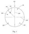
- the dryer drum may be divided into four equal quadrants as shown in FIG. 1 .
- the four quadrants (quadrant one 601, quadrant two 602, quadrant three 603, and quadrant four 604) are determined by the intersection of the x-axis 630 and y-axis 640 of the dryer drum 600.
- the position of the nozzle 610 may then be varied in relation to these quadrants.
- One non-limiting example of placement of the nozzle 610 within the quadrant may be along the quadrant bisection line 612 as shown for the second quadrant 602 in FIG. 1 .
- the nozzle 610 may also be angled in either the left to right direction and/or the up to down direction. This angling of the nozzle is referred to herein as "tilt angle".
- the tilt angle may vary from quadrant to quadrant. For instance, as viewed looking straight into the dryer drum from the door side of the dryer, in the first quadrant 601 the tilt angle may be from about 80° to the left to about 45° to the right and/or from about 45° up to about 35° down. In the second quadrant 602 the tilt angle may vary from about 80° to the right to about 45° to the left and/or from about 45° up to about 35° down.
- the tilt angle may vary from about 80° to the right to about 45° to the left and/or about 45° up and about 15° down.
- the tilt angle may vary from about 80° to the left to about 15° to the right and/or about 45° up and about 15° down.
- the tilt angle is typically selected such that the nozzle is not directly aimed at the dryer vent/lint screen or at the top of the drum. Furthermore, it is generally desirable that the nozzle be angled such that the spray from the nozzle is delivered through the void space/tunnel created by the tumbling of the fabrics around the perimeter of the dryer drum so as to contact the fabrics at the bottom of the rotating circle of fabrics. Also it may be desirable that the nozzle be angled such that the spray intercepts the fabrics being tumbled in the dryer as the fabrics drop from their highest vertical point to their lowest vertical point during dryer drum rotation.
- Each nozzle could be designed to spray concurrently or at different times, flow rate, velocity, etc. than the other nozzle(s).
- the flowrate of the spray in the drum of the fabric article drying appliance such as a tumble dryer is about 0.5 to about 100 ml/minute, about 1 to about 75 ml/minute, about 2 to about 50 ml/minute, or about 15 to about 25 ml/minute.
- One suitable method for determining flow rate is found in ASME/ANSI MFC-9M-1988, entitled "Measurement of Liquid Flow in Closed Conduits by Weighing Method".
- the linear velocity of the spray in the drum of the tumble dryer is about 0.05 to about 2 m/second or about 0.1 to about 1 m/second.
- the length of the spray in the drum of the tumble dryer is from about 20% to about 95% of the length of the drum as measured along the rotational axis of the drum.
- One suitable method for determining linear velocity is by utilizing Laser Doppler Anemometry such as described in “Laser Doppler and Phase Doppler Measurement Techniques" part of the " Experimental Fluid Mechanics " series, written by Albrecht, H.E., Damaschke, N., Borys, M., and Tropea, C., 2003, XIV, 738, page 382.
- the cone angle of the spray refers to the angle the spray forms as it is sprayed into the drum of the tumble dryer. A method for determining cone angle is described below.
- the cone angle of the spray is about 35° to about 150° or about 40° to about 110° or about 50° to about 90°.
- the present invention may include a spraying device for delivering the benefit composition into the tumble dryer.
- the spraying device may be a stand-alone device or it may be incorporated into the fabric article drying appliance.
- spraying device is used interchangeably with the term "fabric article treating apparatus".
- suitable spraying devices which may be used with the present invention are disclosed in the following commonly assigned co-pending applications: U.S. Patent Application Publication No. 2004/0259750, published on December 23, 2004 and entitled “Processes and Apparatuses for Applying a Benefit Composition to One or More Fabric Articles During a Fabric Enhancement Operation”; WO 2004/12007, published on November 4, 2004 and entitled “Volatile Material Delivery Method”; U.S.
- Patent Application Publication No. 2004/0123490 published July 1, 2004 and entitled “Fabric Article Treating Method and Device Comprising a Heating Means”
- U.S. Patent Application Publication No. 2004/0123489 published on July 1, 2004 and entitled “Thermal Protection of Fabric Article Treating Device”
- U.S. Patent Application Publication No. 2004/0134090 published on July 15, 2004 and entitled “Fabric Article Treating Device Comprising More Than One Housing”
- U.S. Application Publication No. 2004/0025368 published on July 29, 2004 and entitled “Fabric Article Treating Apparatus with Safety Device and Controller”
- the spraying system is comprised of a pump, a nozzle, a source of benefit composition, and a conduit as described in further detail below.
- the conduit connects the source of the benefit composition to the pump whereby the benefit composition is discharged through the nozzle of the pump into a tumble dryer.
- the conduit connects the source of the benefit composition to the pump whereby the benefit composition is transported via conduit between the pump and nozzle and then discharged into a tumble dryer.
- the interior of the conduit may be of any shape, non-limiting examples of which include circular and/or oval shaped. It may also be desirable to include a check valve in the conduit before the nozzle. Non-limiting examples of minimum working pressures for the check valve are from about 0.1 psi to about 2 psi or from about 0.5 psi to about 1 psi.
- the pump may be manually operated, and/or the pump may be automated.
- the pump may be mechanically driven, electrically driven, or a combination thereof.
- the spraying system may comprise: a housing or enclosure that contains a source of the fabric treatment composition, such as a reservoir or is in communication with an external source of the fabric treatment composition; an output device, such as a nozzle; a controller, such as an electronic control device with a processing circuit and input and output circuits; one or more sensors, such as a temperature sensor, light sensor, motion sensor, or the like; one or more input devices, such as a start switch and/or a keypad; one or more indicating devices, such as color lights or LED's; and a charging system if the fabric treatment composition is to be electrostatically charged before (or while) being delivered.
- a source of the fabric treatment composition such as a reservoir or is in communication with an external source of the fabric treatment composition
- an output device such as a nozzle
- a controller such as an electronic control device with a processing circuit and input and output circuits
- one or more sensors such as a temperature sensor, light sensor, motion sensor, or the like
- input devices such as a start switch and/
- FIGS. 2 - 5 illustrate one embodiment of an exemplary spray system which may be used in the present invention.
- a "stand-alone” controller and dispenser unit i.e., as a self-contained device
- the enclosure 20 acts as an "inner housing” which is located in the interior of a fabric article drying appliance (e.g., a clothes dryer), while the enclosure 50 acts as an "outer housing” that is located in the exterior of the fabric article drying appliance.
- a fabric article drying appliance e.g., a clothes dryer
- the enclosure 50 may be mounted on the exterior surface of the fabric article drying appliance door, however, it may instead be mounted on any exterior surface, non-limiting examples of which include: the side walls, the top walls, the outer surface of a top-opening lid, and the like, including a wall or other household structure that is separate from the fabric article drying appliance.
- the enclosure 20 may be mounted on any interior surface of the fabric article drying appliance, examples of which include, but are not limited to: the interior surface of the door, the drum of the fabric article drying appliance, the back wall, the inner surface of a top-opening lid, and the like.
- Enclosure 50 may be permanently mounted to the exterior surface, or preferably releasably attached to the exterior surface.
- enclosure 20 may be permanently mounted to the interior surface, or releasably attached to the interior surface.
- FIG. 7 One configuration for such an attachment is illustrated in FIG. 7 , in which the door of the drying appliance is generally designated by the reference numeral 15.
- the enclosure 20 When mounted on the interior surface of the door, for example, the enclosure 20 may be constructed so as to have the appearance of being “permanently” mounted, such that it seems to be “built into” the door of a dryer unit (or other type of fabric article drying appliance), without it actually being truly constructed as part of the fabric article drying appliance.
- enclosure 20 perhaps may be more loosely mounted near the door, or along side the interior surface of the door, much like one of the embodiments 10 as depicted in FIGS. 2 - 5 that "hangs" along a vertical door of the appliance.
- the term "door,” as used herein, represents a movable closure structure that allows a person to access an interior volume of the dryer apparatus, and can be of virtually any physical form that will enable such access.
- the door “closure structure” could be a lid on the upper surface of the dryer apparatus, or a hatch of some sort, or the like.
- the treating apparatus 10 may be grounded by way of being in contact with a grounded part of the fabric article drying appliance such as by a spring, patch, magnet, screw, or other attaching means, and/or by arc corona discharge, or by way of dissipating residual charge.
- a grounded part of the fabric article drying appliance such as by a spring, patch, magnet, screw, or other attaching means, and/or by arc corona discharge, or by way of dissipating residual charge.
- a grounded part of the fabric article drying appliance such as by a spring, patch, magnet, screw, or other attaching means
- arc corona discharge or by way of dissipating residual charge.
- One non-limiting way of dissipating the charge is by using an ionizing feature, for example a set of metallic wires extending away from the source.
- fabric article drying appliances such as clothes dryers have an enameled surface.
- One method of grounding would be to ground to the enameled surface of the fabric article drying appliance by
- Another method of grounding to the non-conductive surface of a fabric article drying appliance comprises the usage of a thin metal plate that is positioned between the fabric article drying appliance and the fabric article treating device which serves to provide a capacitive discharge.
- Typical thickness of such a plate is from about 5 microns to about 5000 microns.
- a discharge nozzle 24 and a "door sensor" 22 are visible on the inner housing 20, which also includes a benefit composition-holding reservoir 26 within an interior volume of the inner housing 20.
- the reservoir 26 may be used to hold a benefit composition.
- the discharge nozzle 24 can act as a fluid atomizing nozzle, using either a pressurized spray or, along with an optional high voltage power supply (not shown in FIG. 2 ) it can act as an electrostatic nozzle.
- the benefit composition can comprise a fluidic substance, such as a liquid or a gaseous compound, or it can comprise a solid compound in the form of particles, such as a powder, or solid particles in solution with a liquid.
- Reservoir 26 can be of essentially any size and shape, and could take the form, for example, of a pouch or a cartridge; or perhaps the reservoir could merely be a household water line for situations in which the benefit composition comprises potable water.
- the inner housing 20 and outer housing 50 are typically in electrical communication.
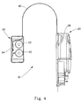
- a flat cable 40 (also sometimes referred to as a "ribbon cable”) is run between the two housings 20 and 50, and travels along the inner surface of the fabric article drying appliance door 15 (see FIG. 7 , for example), over the top of the door 15, and down the exterior surface of the door 15.
- FIG. 3 shows the same fabric article treating apparatus 10 from an opposite angle, in which the outer housing 50 is provided with an ON-OFF switch at 56.
- the flat cable 40 is again visible in FIG. 3 , and along the surface of the inner housing 20 visible in FIG. 3 , a door mounting strap 21 is visible. An end of the mounting strap is also visible in FIG. 2 .
- a dryer door 15 or other interior surface
- the fabric article treating apparatus 10 is illustrated such that the reservoir 26 can be seen as an interior volume of the inner housing 20.
- a set of batteries 52 can be seen, as well as a printed circuit board with electronic components at 54. It will be understood that any type of electrical power source could be used in the present invention, including standard household line voltage, batteries, or even solar power.
- the discharge nozzle 24 acts as an electrostatic nozzle, and thereby is coupled with a high voltage power supply 28, by use of an electrical conductor not shown in this view.
- a quick disconnect switch 34 is included for safety purposes, so that the high voltage power supply 28 can be quickly shut down if necessary.
- a pump 30 and a corresponding electric motor 32 are visible in FIG. 5 .
- Some type of pumping apparatus is used regardless as to whether the discharge nozzle 24 is producing a pressurized spray only, or an electrostatic spray that utilizes a high voltage power supply 28.
- FIG. 6 provides a block diagram of some of the electrical and mechanical components that may be included in a fabric article treating apparatus 10, suitable for use with the present invention.
- the high voltage power supply 28 is provided in the inner housing 20, which will be used to electrically charge the fluid that will be dispensed through the discharge nozzle 24, thus making this an electrostatic nozzle system.
- the inner housing 20 utilizes a general body or enclosure to contain the devices needed within the drying appliance, and it will be understood that such components will generally be subjected to relatively high temperatures during the treatment cycle of the drying appliance. Consequently, the more sensitive electronic components will generally (but not always) be mounted in a different location, such as in the outer housing 50.
- the flat cable 40 will bring certain command signals and electrical power into the inner housing 20, and will also receive electrical signals from sensors mounted in the inner housing 20 and communicate those sensor signals back to the outer housing 50.
- a power supply control signal follows a wire 70 through the quick disconnect switch 34 to the high voltage power supply 28.
- This signal can comprise a constant DC voltage, a constant AC voltage, a variable DC voltage, a variable AC voltage, or some type of pulse voltage, depending on the type of control methodology selected by the designer of the fabric article treating apparatus 10.
- the signal at 70 is a variable DC voltage, and as this voltage increases, the output of the high voltage power supply 28 will also increase in voltage magnitude, along a conductor 39 (e.g., a wire) that is attached to an electrode 38 that carries the high voltage to the nozzle 24, or into the reservoir 26. The voltage impressed onto the electrode 38 will then be transferred into the benefit composition.
- a constant output voltage DC high voltage power supply could optionally be used instead of the variable output voltage power supply 28 of the exemplary embodiment.
- the benefit composition Once the benefit composition is charged within the reservoir 26 it will travel through a tube or channel 42 to the inlet of the pump 30, after which the composition will be pressurized and travel through the outlet of the pump along another tube (or channel) 44 to the discharge nozzle 24.
- the actual details of the type of tubing used, the type of pump 30, and the type of electric motor 32 that drives the pump, can be readily configured for almost any type of pressure and flow requirements.
- the electrical voltage and current requirements of the electric motor 32 to provide the desired pressure and flow on the outlet of the pump 30 can also be readily configured for use in the present invention.
- Virtually any type of pump and electric motor combination can be utilized in some form or another to create a useful device that falls within the teachings of the present invention, or a stand-alone pump can be used (i.e., without an associated electric motor).
- peristaltic pumps in which the pump acts upon a continuous tube that extends through an inlet opening and continues through a discharge opening of the pump.
- This arrangement is particularly beneficial for use with electrostatically charged fluids or particles that are being pumped toward the discharge nozzle 24, because the tubing can electrically insulate the pump from the charged benefit composition.
- an alternative pumping device could be used, if desired, such as a spring-actuated pumping mechanism.
- a non-limiting example of a suitable peristaltic pump is the Model 10/30 peristaltic pump, which may be obtained from Thomas Industries of Louisville, Kentucky.
- the fabric article treating apparatus 10 can be enhanced by use of certain sensors, examples of which include but are not limited to a door (or lid) sensor 22, a motion sensor 36, a humidity sensor 46, and/or a temperature sensor 48.
- FIG. 7 diagrammatically shows the general location of some of the components of one of the stand-alone embodiments of the fabric article treating apparatus 10 which may be used with the present invention.
- the electronics 54 and the batteries 52 are located within the outer housing 50, which is electrically connected to a flat cable 40 that carries power supply and input/output signals between the outer housing 50 and the inner housing 20.
- the electrical conductor 39 is depicted, which carries the high voltage to the nozzle 24, and this is one configuration that could be alternatively used instead of carrying the high voltage to the reservoir 26.
- the tubing 42 to the inlet of the pump is illustrated, as well as the tubing 44 from the outlet of the pump that provides the benefit composition to the nozzle 24.
- the high voltage power supply 28 is strictly optional within the teachings of the present invention; if spray droplets/particles emitted from the nozzle 24 are not to be electrostatically charged, then there is no need for a high voltage power supply within the inner housing 20.
- FIG. 8 illustrates an alternative embodiment for use with the present invention, which depicts a fabric article drying appliance generally designated by the reference numeral 110.
- the controller depicted in the stand-alone embodiment of the earlier figures is now integrated into the electronic control system of the drying appliance 110.
- a door 15 is illustrated in FIG. 8 , which is the normal point of access by a human user to the interior drum volume of the drying appliance 110.
- a nozzle 24 is used to direct a benefit composition into the drum area, in which the drum is generally designated by the reference numeral 114.
- a supply pipe 44 brings the benefit composition to the nozzle 24, through a control valve 120, that can have an ON/OFF push button 56, if desired.
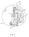
- FIG. 9 illustrates an alternative stand-alone embodiment of the present invention, generally designated by the reference numeral 150.
- Components illustrated in FIG. 9 include a reservoir (or chamber) 26, an optional charging component 39 (such as an electrode or other type of electrical conductor that transports a high voltage to the reservoir or to the nozzle), a discharge nozzle 24, a pump unit 30, and a set of batteries 52.
- An electronic printed circuit board 54 is provided, which would typically include a microcontroller or other type of control circuit.
- One or more sensors may be included in such a device, as depicted at the reference numeral 129, and may include a pressure sensor, a door sensor 22, motion sensor 36, humidity sensor 46, and/or a temperature sensor 48.
- all of the components are enclosed in a single housing, and the entire unit is positioned within a fabric article drying appliance, such as a conventional clothes dryer found in a consumer's home.
- the "single-housing" stand-alone unit 150 of FIG. 9 can incorporate all of the electrical and electronic components that are described herein with respect to FIG. 6 - 7 .
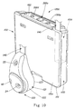
- FIGS. 10 - 14 where like reference numerals indicate like elements, a benefit composition dispensing apparatus 1100 constructed in accordance with a third embodiment of the present invention is illustrated.
- the apparatus 1100 comprises two enclosures or housings 1120 and 1150.
- Enclosure 1120 defines an "inner housing” located in an interior of a fabric enhancement apparatus such as a fabric article drying appliance, e.g., a clothes dryer (not shown in FIGS. 10 - 14 ), while the enclosure 1150 defines an "outer housing" located outside of the fabric article drying appliance.
- the fabric enhancement apparatus may also comprise a laundry apparatus or a laundry and drying apparatus.
- the enclosure 1150 may be mounted on an exterior surface of the fabric enhancement apparatus door (not shown), such as by pressure sensitive, thermally stable adhesive foam strips (not shown). Alternatively, the enclosure 1150 may be mounted on any other exterior surface of the fabric enhancement apparatus, non-limiting examples of which include: side walls, top walls, an outer surface of a top-opening lid, and the like. The enclosure 1150 may also be mounted on a wall or other household structure that is separate from the fabric enhancement apparatus.
- the enclosure 1120 may be mounted, such as by pressure sensitive, thermally stable adhesive foam strips (not shown), on any interior surface of the fabric enhancement apparatus, examples of which include, but are not limited to: the interior surface of the door, a drum of the apparatus, the back wall, the inner surface of a top-opening lid, and the like.
- the inner housing enclosure 1120 comprises a main body 1121 comprising an integral front/side main section 1122 and a back plate section 1123 secured to the main section 1122 via screws, adhesive, snap-fit elements or the like.
- the sections 1122 and 1123 are preferably molded from a polymeric material.
- Housed within the main body 1121 may be the following elements: a discharge nozzle 24; a door sensor 22 for sensing ambient light when the door of the fabric enhancement apparatus is open such that the sensor 22 is exposed to ambient light; a motion sensor 36 (contained within the main body 1121 and not visible from outside the main body 1121); a humidity sensor 46 (not shown in Figs. 10 and 11 ); and a temperature sensor 48.
- the nozzle 24 is not combined with a high voltage power supply.
- the nozzle 24 functions as a fluid atomizing nozzle so as to generate a pressurized spray.
- the enclosure 1150 comprises a main body 1151 having a back wall 1151 a, a first inner compartment 1151 b, for storing varying lengths of unused cable 1140, to be described below, and a second compartment 1151c, for storing a fluid pump 1130, a motor 1132 for driving the pump 1130, batteries 52, a tube 1142 (to be discussed below) and a portion of a tube 1144 (to be discussed below).
- the enclosure 1150 further comprises a cassette door 1152 pivotably coupled to the main body 1151 such as by pins 1152a (only one of which is illustrated in Fig. 12 ), a printed circuit board 1160a and a face plate 1162.
- the printed circuit board 1160a is housed between the main body 1151 and the face plate 1162.
- the face plate 1162 is coupled to the main body 1151 via screws, adhesive, snap-fit elements, or like coupling elements.
- the pivotable door 1152 comprises a pocket 1152b for receiving a fluid reservoir defined by a removable container 1170 filled with a benefit composition, which composition may comprise any one of the benefit compositions discussed in this document or the documents noted herein.
- the container 1170 may be formed from a polymeric material, paper, foil, a combination of these materials or a like material.
- the door 1152 is releasably held in a closed position within the main body 1151 via first and second flex arms 1153, which are coupled to the main body 1151.
- the cable 1140 is coupled to and extends between the enclosures 1120 and 1150.
- the cable 1140 may run along the inner surface of the fabric enhancement apparatus door, over the top of the door, and down the exterior surface of the door. Any unused length of the cable 1140 can be manually inserted into the first compartment 1151b for storage.
- the cable 1140 carries benefit composition from the fluid pump 1130 in the outer enclosure 1150 to the nozzle 24 in the inner enclosure 1120, see FIG. 14 , and electrical signals from the sensors 36, 22, 46 and 48 mounted in the inner enclosure 1120 to a microcontroller 1160 mounted to the printed circuit board 1160a in the outer enclosure 1150.
- a first fitment 1172 is mounted to the main body 1151 via first and second mounting shelves 1155a and 1155b, see FIGS. 12 and 13 , and is coupled to the tube or channel 1142 (not shown in FIG. 13 ), which, in turn, is coupled to the pump 1130.
- the first and second shelves 1155a and 1155b are positioned on opposing sides of a flange 1172a of the first fitment 1172 and are snap fit, adhesively secured or bolted together so as to encompass the flange 1172a.
- the assembly comprising the shelves 1155a and 1155b and fitment 1172 is mounted to the main body 1151 such that the shelves 1155a and 1155b are received within a slot 1151d defined in the main body 1151.
- the fitment 1172 is inserted into a second fitment 1170a forming part of the fluid container 1170 when the door 1152 is pivoted to its closed position and functions to pierce or otherwise penetrate the container 1170 so as to provide a pathway for the benefit composition to travel from the container 1170 to the tube 1142.
- the benefit composition travels to the inlet of the pump 1130, after which the composition is pressurized and carried via the tube or channel 1144 (shown in FIG. 12 ), which extends through the cable 1140, to the discharge nozzle 24, where the benefit composition is discharged.
- the pump 1130 and the motor 1132 comprises a single assembly, namely, a piezoelectric pump, one of which is commercially available from Par Technologies, LLC, under the product designation LPD-30S.
- suitable pumps which can be used in this or other embodiments include but are not limited to gear pumps and diaphragm pumps.
- a suitable diaphragm pump is model No. NF5RPDC-S with a DC motor available from KNF Neuberger, Inc. of Trenton, New Jersey.
- control signals used to control the electric motor 1132 can vary according to the design requirements of the apparatus 1100, and such signals will travel to the motor 1132 via an electrical conductor 1172.
- the electrical signal traveling along conductor 1172 comprises a pulse-width modulated (PWM) signal controlled by the microcontroller 1160.
- PWM pulse-width modulated
- Such a pulse-width modulated signal can also be generated by any appropriate controller or processor, or appropriate discrete logic.
- the enclosure 1150 comprises a second compartment 1151c for storing batteries 52, which may comprise two AA batteries.
- the batteries 52 define a power source, which provide a DC voltage to a DC power supply 1158, see FIG. 14 .
- An example DC power supply comprises an integrated circuit chip commercially available from Maxim Integrated Products under the product designation "MAX1724EZK50-T.”
- the DC power supply 1158 provides an output voltage to the microcontroller 1160.
- a suitable microcontroller 1160 is a microprocessor manufactured by Atmel Corporation and sold under the product designation Atmega48-16A1.
- the microcontroller 1160 may comprise a microprocessor manufactured by Atmel Corporation and sold under the product designation Atmega48-16AJ.
- other microcontrollers, microprocessors, controllers, or processors made by different manufacturers, or discrete digital logic could alternatively be used.
- the microcontroller 1160 includes on-board memory and input and output lines for analog and digital signals.
- the microcontroller 1160 also has a serial port that can be interfaced to an optional programmer interface using an RS-232 communications link.
- the ON-OFF switch 1266c, and the refluff key 266d are coupled to the microcontroller 1160, see FIG. 14 .
- the motion sensor 36, door sensor 22, humidity sensor 46 and temperature sensor 48 generate signals to the microcontroller 1160.
- the microcontroller 60 generates a pulse-width modulated (PWM) signal to the pump motor 1132 via the conductor 1172.
- PWM pulse-width modulated
- An audio indicator 1300 is further coupled to the microcontroller 1160 and functions to indicate that a drying cycle has been completed, clothes have been treated with the benefit composition, an error occurred during the benefit composition dosing cycle or the benefit composition dispensing apparatus is out of fluid.
- the audio indicator 1300 is mounted to the printed circuit board 1160, see FIG. 12 .
- first, second, third, fourth and fifth light emitting diodes 1400a-1400e are coupled to the face plate 1162 so as to be visible to an operator when actuated, see FIG. 11 .
- the first diode 1400a is actuated by the microcontroller 1160 when the apparatus 1100 is activated via the ON-OFF switch 1266c.
- the second diode 1400b is actuated by the microcontroller 1160 when the pump 1130 is pumping benefit composition to the nozzle 24.
- the third diode 1400c is actuated by the microcontroller 1160 when the refluff key 266d has been activated.
- the fourth diode 1400d is actuated by the microcontroller 1160 when the spraying operation has been completed for the corresponding fabric enhancement operation cycle.
- the fifth diode 1400e is actuated by the microcontroller 1160 to generate a warning signal when the container is out of fluid, or the fabric enhancement cycle has been interrupted, which latter event may be detected via the door sensor 22 sensing light or the motion sensor 36 sensing no motion.
- the microcontroller 1160 may sense that the container 1170 is out of fluid by sensing a change in the current drawn by the pump motor 1132.
- a treatment material provides one or more fabric benefits including, but not limited to, softness, anti-soil re-deposition, stain or water repellency, color or whiteness enhancement, fragrance, enhanced absorbency, anti-static, anti-bacterial, wrinkle control, shape/form retention, and/or fabric abrasion resistance.
- Classes of materials that contain materials that can provide such benefits include, but are not limited to, cationic materials, nonionic materials, other polymeric materials, and particulate materials.
- the treatment material is present, based on total composition weight, at one of the following levels, at least about 0.5 wt %, at least about 2 wt %, from about 4 wt % to about 90 wt %, from about 4 wt % to about 50 wt %, or from about 4 wt % to about 10 wt %.
- Suitable treatment materials include but are not limited to those disclosed in WO 2004/12007, published on November 4, 2004 and entitled “Volatile Material Delivery Method”; WO 00/24856, published on May 4, 2000 and entitled “Fabric Care Composition and Method”; U.S. Patent Application Publication No. 2005/0022311 published on February 3, 2005 and entitled “Fabric Article Treating System and Method”; U.S. Patent Application Publication No. 2005/0076534, published on April 14, 2005 and entitled “Fabric Article Treating Device and System with Static Control”.
- the fabric treatment composition used in conjunction with the present invention may include a perfume.
- the perfume may comprise at least about 0.005 wt. %, about 0.005 wt. % to about 10 wt% or about 0.1 wt. % to about 2 wt. % of a material such as a perfume that comprises at least about 30 wt.%, about 35 wt % to about 100 wt.
- the fabric treatment composition used in conjunction with the present invention may also include from about 0.5 to about 20% of fabric softeners or fabric hand modifiers non-limiting examples of which include diester quaternary ammonium compounds, polyquaternary ammonium compounds, triethanolamene esterified with carboxylic acid and quatemized materials, amino esterquats, cationic diesters, betain esters, betaines, silicone or silicone emulsions comprising amino silicones, cationic silicones, quat/silicone mixtures, functionalized polydimethyl siloxanes
- PDMS poly(ethylene emulsion)
- amine oxides silicone co-polyols
- cationic starches sucrose fatty esters, polyethylene emulsions, and mixtures thereof.
- the fabric treatment composition used in conjunction with the present invention may also include from about 0.1 to about 1.2% of antistatic agents non-limiting examples of which include polyanilines, polypyrroles, poly acetylene, polyphenylene, polythiophenes, ethoxylated polyethyleneimines, and various commercial materials such as STATEXAN WP, STATEXAN HA, or STATEXAN PES (available from LanXess-- a subsidiary of Bayer located in Leverkusen, Germany), ETHOFAT (available from Akso Nobel of Arnhem, Netherlands),and mixtures thereof.
- antistatic agents non-limiting examples of which include polyanilines, polypyrroles, poly acetylene, polyphenylene, polythiophenes, ethoxylated polyethyleneimines, and various commercial materials such as STATEXAN WP, STATEXAN HA, or STATEXAN PES (available from LanXess-- a subsidiary of Bayer located in Leverkusen, Germany),
- the fabric treatment composition used in conjunction with the present invention may also include from about 0.005 to about 1.5% of malodor control agents non-limiting examples of which include substituted or unsubstituted cyclodextrins, porous inorganic materials, starch, olfactory odor blockers and mixtures thereof.
- the fabric treatment composition used in conjunction with the present invention may also include from about 0.05 to about 0.5% of preservatives non-limiting examples of which include didecyl dimethyl ammonium chloride which is available under the tradeneme UNIQUAT ® (from Lonza of Basel Switzerland), 1,2-benzisothiozolin-3-one, which is available under the tradename PROXEL ® (from Arch Chemicals of Norwalk, Connecticut), dimethylol-5,5-dimethylhydantoin which is available under the tradeneme DANTOGUARD ® (from Lonza of Basel Switzerland), 5-Chloro-2-methyl-4-isothiazolin-3-one / 2-methyl-4-isothiazolin-3-one, which is available under the tradename KATHON ® (from Rohm and Haas of Philadelphia, Pennnsylvania), and mixtures thereof.
- preservatives non-limiting examples of which include didecyl dimethyl ammonium chloride which is available under the tradeneme UNIQUAT
- the fabric treatment composition used in conjunction with the present invention may also include from about 0.05 to about 5% of ethoxylated surfactants and/or emulsifiers. These may include, but are not limited to carboxylated alcohol ethoxylates, ethoxylated quaternary ammonium surfactants, ethoxylated alkyl amines, alkyl phenol ethoxylates, alkyl ethoxylates, alkyl sulfates, alkyl ethoxy sulfates, polyethylene glycol/polypropylene glycol block copolymers, fatty alcohol and fatty acid ethoxylates, long chain tertiary amine oxides, alkyl polysaccharides, polyethylene glycol (“PEG”) glyceryl fatty esters and mixtures thereof.
- ethoxylated surfactants and/or emulsifiers may include, but are not limited to carboxylated alcohol ethoxylates, e
- the fabric treatment compositions of the present invention can be formulated into any suitable form and prepared by any process chosen by the formulator, non-limiting examples of which are described in U.S. Patent No. 6,653,275 .
- a treatment composition applied during the drying process be uniformly distributed onto the fabric in the tumble dryer during the drying process. It is also desirable during the drying process that a treatment composition be deposited on the fabric that is in the tumble dryer rather than deposited elsewhere such as through the dryer vent/lint screen. While not wishing to be limited by theory it is believed that some factors which may possibly influence both uniformity of distribution and deposition of the treatment composition onto the fabric in the drum of the tumble dryer include flowrate of the treatment composition in the drum, the droplet size of the treatment composition, the position of the spray in the drum, the cone angle of the spray in the drum, the linear velocity of the treatment composition in the drum.
- the uniformity of distribution (i.e.; Distribution Index) of the treatment composition on the fabric in the drum of the tumble dryer be at least about 35%, at least about 45%, at least about 50%, at least about 60%, at least about 70%, at least about 75%, or at least about 80%. It is desirable that the deposition of the treatment composition onto the fabric in the drum of the tumble dryer be at least about 70%, at least about 75%, or at least about 80%.
- the following method may be used to measure the cone angle (width of a spray).
- Lint screen The fabric over the lint screen is sampled as follows:
- ICP Inductively Coupled Plasma Optical Emission Spectrometry
- Yttrium Y
- the distribution of Y is representative of the distribution of the treatment composition solution.
- Image analysis may be used to evaluate uniformity of spray distribution per surface area of a test sample.
- a number of digital images are acquired per sample by imaging equipment and analyzed by computer software.
- the software detects a spray deposition area and provides a count of the number of pixels comprising the stained areas in the image. By comparison of the number of pixels detected for all images taken per sample, a standard deviation is calculated. A smaller standard deviation correlates to a more uniform spray deposition.
- red dye i.e.; 0.0 wt 5% FD&C Red Dye #40 in distilled water.
- Image analysis is then conducted according to the following steps to evaluate the uniformity of distribution of spray on a sample.
- the picture is digitized (i.e. converted to a binary representation) in a known manner.
- the digital image data is transferred to a computing device.
- Many other methods of acquiring the digital image are well known to persons of ordinary skill in the art. For example, a sample to be analyzed may be submitted via the network, a file may be retrieved from a database, and/or a flatbed scanner may be used to digitize a photograph.
- the image is electronically processed by image analysis software (Optimas v6.5 available from Media Cybernetics, Incorporated of Silver Spring, Maryland) based on a reference intensity threshold.
- the region of interest selected is the entire screen image.
- the method for selecting the intensity threshold setting is as follows.
- the background and color corrected images of the fabric (step 1 above) are converted to a single 'gray' level image representation that highlights the difference between the red dyed areas and 'clean' fabric areas.
- the method used depends upon the lighting, imaging system, and type and color of dye used vs. the background fabric color. For example the green channel can be used.
- an intensity image from Red - Green , Red - Blue or other similar mathematical combinations of the Red, Green, and Blue color channels of an image can be used to create a single channel 'gray' level image for thresholding that accentuates the differences between the dyed and 'clean' areas of the fabric.
- the software is calibrated to detect colored areas in pixels of the digital images.
- a "clean", un-dyed white fabric is the standard reference and is imaged according to step (1).
- the threshold is set for which zero pixels are detected for all images for that "clean” sample, and such that increasing the threshold value any higher would make the software start detecting pixels on the "clean” sample. Pixels of a color intensity value within the set threshold are detected and counted by the image analysis software.
- treatment compositions which may be useful in the present invention:
- Non-limiting examples of nozzle placements which may be used in a tumble dryer A.
- Non-limiting examples of nozzle placements which may be used with a cross-flow tumble dryer i.e.; where the drum typically rotates in a counter-clockwise motion, and air flow typically enters the tumble dryer through a rear panel in quadrant 602 and exits through the rear panel of the dryer in quadrant 601-- see Fig. 1 ).
- Example 1 2 3 4 5 6 7 8 9 10 11 12 13 Number of nozzles 1 1 1 1 1 1 1 1 1 2 2 1 1 2 Dryer panel 1 F F F F F F F F F F F F B B F/B Quadrant 2 O O O 2 2 3 3 1 1/2 2/4 2 O 2/O Vertical displacement 3 (%) 0 0 0 40 10 30 5 30 15/30 40/20 30 0 25/0 Horizontal displacement 4 (%) 0 0 0 0 20 30 10 5 20 10/15 40/5 10 0 20/0 Nozzle angle (degrees up (“U") or down (“D")) 0 30 D 15 U 45 D 0 10 U 55 U 30 D 45/15 D/D 0/15 /U 25 D 5 D 15/1 5 D/D Nozzle angle (degrees left (“L”) or right (“R")) 5 0 20 L 55 L 15 R 5 R 15 R 25 L 45 L 45/0 L / 30/45 R/L 10 R 15 L 0/10 /L 1 Denotes nozzle placement on the front ("F") panel/door of
Abstract
Description
- The present invention relates to the uniform delivery of treatment materials in fabric article drying appliances such as tumble dryers. A device for depositing such materials is known from applicants
US 2004/25368 . - Traditionally when applying treatment materials to fabrics in a fabric article drying appliance such as a tumble dryer, it has been difficult to achieve a uniform distribution of the treatment material onto the fabric. If the distribution of the treatment material is not uniform, this results in areas of the fabric being left untreated. This uneven distribution further results in undesirable fabric attributes which can interfere with such things as the look, touch, smell, and longevity of the fabric. Additionally, in many instances, it has also been observed that rather than being desirably deposited onto the fabric, the treatment material ends up elsewhere such as being lost through the fabric article drying appliance vent. Hence, not only is uniform distribution of the treatment material on the fabric important, but also providing efficient delivery of the treatment material to the fabric such that the treatment material ends up on the fabric and not elsewhere.
- Accordingly, there is a need to provide a convenient and effective way of uniformly and efficiently delivering treatment materials to fabrics in a fabric article drying appliance. The present invention addresses this need.
- The present invention relates to a device for depositing benefit composition In a fabric article drying appliance (110), the device comprising a pump, the pump (30) comprising: a) a conduit wherein the conduit includes an inlet and a discharge; and b) a nozzle (610) having one or more orifices connected to the discharge of the conduit; wherein the inlet of the conduit is in communication with a source of benefit composition so as to dispense the benefit composition through the conduit from the source of benefit composition to the nozzle whereby the benefit composition is dispensed from the nozzle (610) into the fabric article drying appliance whereby the benefit composition has a mean droplet size of from 100 microns to 1000 microns and wherein the cone angle formed by the benefit composition that is discharged from the nozzle is between 35° and 150°; and wherein the nozzle is positioned into a fabric article drying appliance such that it is in quadrant one (601), quadrant two (602), quadrant three (603), quadrant four (604), or a combination thereof, and wherein the nozzle when present in quadrant one (601) has a tilt angle ranging from 80° to the left to 45° to the right and from 45° up to 35° down; when present in quadrant two (602) the nozzle has a tilt angle ranging from 80° to the right to 45° to the left and from 45° up to 15° down; when present in quadrant three (603) the nozzle has a tilt angle ranging from 80° to the right to 45° to the left and from 45° up to 15° down; when present in quadrant four (604) the nozzle has a tilt angle ranging from 80° to the left to 15° to the right and from 45° up to 15° down, and combinations thereof.
- The invention also relates to a method for providing efficient deposition of a benefit agent according to the features of claim 12 and to a system according to claim 13.
- Further embodiments of the invention are defined in the dependent claims.
-
-
FIG. 1 is a front view of a dryer drum. -
FIG. 2 is a perspective view of an embodiment of a stand-alone fabric article treating apparatus made according to the principles of the present invention. -
FIG. 3 is a perspective view from the opposite angle of the fabric article treating apparatus ofFIG. 2 . -
FIG. 4 is an elevational view from one end in partial cross-section of the fabric article treating apparatus ofFIG. 2 , illustrating the internal housing and external housing, as joined together by a flat cable. -
FIG. 5 is an elevational view from one side in partial cross-section of the internal housing portion of the fabric article treating apparatus ofFIG. 2 . -
FIG. 6 is a block diagram of some of the electrical and mechanical components utilized in the fabric article treating apparatus ofFIG. 2 . -
FIG. 7 is a diagrammatic view in partial cross-section of the fabric article treating apparatus ofFIG. 2 , as it is mounted to the door of a clothes dryer apparatus. -
FIG. 8 is a perspective view of a fabric article drying appliance that has a nozzle which sprays a benefit composition into the drum portion of the dryer, as constructed according to the principles of the present invention. -
FIG. 9 is a diagrammatic view of some of the components utilized by an alternative embodiment stand-alone fabric article treating apparatus that is constructed according to the principles of the present invention, in which the entire treating apparatus is contained within a single housing or enclosure. -
FIG. 10 is a perspective view of another embodiment of a stand-alone unit for dispensing a benefit composition constructed according to the principles of the present invention. -
FIG. 11 is a perspective view from an opposite angle of the unit ofFig. 10 . -
FIG. 12 is an exploded view of the unit illustrated inFIGS. 10 and11 . -
FIG. 13 is an exploded view of the fluid container, the first and second fitments and the first and second mounting shelves. -
FIG. 14 is a block diagram of at least a portion of the electrical and mechanical components utilized in the unit ofFIGS. 11 - 13 . - The present invention relates to the uniform distribution of treatment material onto fabrics in fabric article drying appliances such as tumble dryers. In another aspect, the invention relates to efficiently depositing the treatment materials on the fabric so that the materials are deposited on the fabric and not elsewhere.
- As used herein, "fabric article" means an article that comprises a fabric. Such articles include, but are not limited to, clothing, shoes, curtains, towels, linens, upholstery coverings and cleaning implements.
- As used herein, "during a dryer cycle" means while the dryer is operating.
- As used herein, "treatment material" means a material or combination of materials that can deliver benefits to a fabric article. Examples of such benefits include but are not limited to; softening, crispness, water and/or stain repellency, refreshing, antistatic, anti-shrinkage, antimicrobial, durable press, wrinkle resistance, odor resistance, abrasion resistance, anti-felting, anti-pilling, dimensional stability, appearance enhancement such as color and whiteness enhancement, anti-soil redeposition, fragrance, enhanced absorbency, and mixtures thereof.
- As used herein, "fabric treatment composition" means a composition that comprises one or more treatment materials. Suitable forms of fabric treatment compositions include, but are not limited to, fluidic substances, such as liquids or gases, and solid compounds, such particles or powders.
- As used herein, the terms "treatment material", "treatment composition", "fabric treatment composition" and "benefit composition" are used interchangeably.
- As used herein, the articles "a", "an", and "the" when used in a claim, are understood to mean one or more of the material that is claimed or described.
- Unless otherwise noted, all component or composition levels are in reference to the active level of that component or composition, and are exclusive of impurities, for example, residual solvents or by-products, which may be present in commercially available sources.
- Unless otherwise indicated, all percentages and ratios are calculated based on weight of the total composition.
- Unless otherwise indicated, all measurements herein were performed at a standard atmospheric pressure of about 1 bar.
- It should be understood that every maximum numerical limitation given throughout this specification includes every lower numerical limitation, as if such lower numerical limitations were expressly written herein. Every minimum numerical limitation given throughout this specification will include every higher numerical limitation, as if such higher numerical limitations were expressly written herein. Every numerical range given throughout this specification will include every narrower numerical range that falls within such broader numerical range, as if such narrower numerical ranges were all expressly written herein.
- In one aspect of the present invention, the delivery system is comprised of a spray for delivering treatment materials to fabrics in a fabric article drying appliance such as a tumble dryer. The dryer drum is typically rotating during delivery of the treatment materials but may also be stationary during delivery. The spray comprises a treatment composition. The treatment composition comprising the spray of the present invention has a mean droplet size of about 100 microns to about 1400 microns, about 200 microns to about 1300 microns, about 300 microns to about 1200 microns, or about 500 microns to about 1100 microns. A suitable instrument for measuring droplet size is the Malvem particle sizer manufactured by Malvern Instruments Ltd. of Framingham, Massachusetts.
- The viscosity of the treatment composition comprising the spray, as measured at approximately 24°C using a Model DV-11 Brookfield Viscometer with a LV I spindle, is about 200 cps or less, about 100 cps or less, or about 50 cps or less. The Brookfield Model DV-II viscometer is available from Brookfield of Middleboro, Massachusetts. The static surface tension of the treatment composition comprising the spray as measured between approximately 20°C - 25°C is about 3 to about 100 dynes/cm, about 4 to about 70 dynes/cm, or about 5 to about 40 dynes/cm. A suitable instrument for measuring static surface tension is a Kruss Tensiometer, Model K12 manufactured by Kruss of Matthews, North Carolina.
- The treatment composition may be sprayed through a nozzle and into the drum of a fabric article drying appliance such as the drum of a tumble dryer. The nozzle typically will have a diameter of about 200 to about 600 microns or about 250 to about 400 microns. A non-limiting example of a nozzle suitable for this purpose is a pressure swirl atomizing nozzle. Non-limiting examples of suitable nozzles include the Cosmos 13 NBU nozzle manufactured by Precision Valve Corporation of Marietta, Georgia, the WX12 and WD32 nozzles manufactured by Saint-Gobain Calmar USA, Inc. of City of Industry, California, and Seaquist Model No. DU-3813 manufactured by Seaquist Dispensing of Cary, Illinois. The nozzle may be in association with a spraying device. The nozzle may be permanently attached or releaseably attached to a spraying device. One non-limiting example of a releaseably attached nozzle is a nozzle which is threaded such that it can easily be removed from or placed in a spraying device. The nozzle may be disposable. The spraying device may be free standing or it may be associated with the drying appliance as discussed in further detail below.
- It is desirable that the fabrics in the fabric article drying appliance not come into direct contact with the nozzle while the nozzle is operating as this may inhibit flow from the nozzle. Hence, it may be desirable for the nozzle to include a deflector which deflects the fabric away from the nozzle. The deflector may surround all or a portion of the nozzle (for example the top portion of the nozzle). The degree of extension of the deflector into the fabric article drying appliance is selected so as to insure that the deflector does not intercept the cone angle of the spray under normal use conditions. The deflector may be made from any suitable material, non-limiting examples of which include plastic, metal, Plexiglas, and the like. The deflector may be of any shape provided that the shape selected does not negatively impact fabric integrity during tumble drying process (i.e.; no sharp edges/corners or rough surfaces).
- The placement of the nozzle and angle of the nozzle may be varied so as to optimize spray contact with the fabric in the tumble dryer. In order to facilitate the determination of where the nozzle should be positioned in relation to optimizing spray contact with the fabric, the dryer drum may be divided into four equal quadrants as shown in
FIG. 1 . The four quadrants (quadrant one 601, quadrant two 602, quadrant three 603, and quadrant four 604) are determined by the intersection of thex-axis 630 and y-axis 640 of thedryer drum 600. The position of thenozzle 610 may then be varied in relation to these quadrants. One non-limiting example of placement of thenozzle 610 within the quadrant may be along the quadrant bisection line 612 as shown for thesecond quadrant 602 inFIG. 1 . - The
nozzle 610 may also be angled in either the left to right direction and/or the up to down direction. This angling of the nozzle is referred to herein as "tilt angle". The tilt angle may vary from quadrant to quadrant. For instance, as viewed looking straight into the dryer drum from the door side of the dryer, in thefirst quadrant 601 the tilt angle may be from about 80° to the left to about 45° to the right and/or from about 45° up to about 35° down. In thesecond quadrant 602 the tilt angle may vary from about 80° to the right to about 45° to the left and/or from about 45° up to about 35° down. In thethird quadrant 603 the tilt angle may vary from about 80° to the right to about 45° to the left and/or about 45° up and about 15° down. In thefourth quadrant 604 the tilt angle may vary from about 80° to the left to about 15° to the right and/or about 45° up and about 15° down. - The tilt angle is typically selected such that the nozzle is not directly aimed at the dryer vent/lint screen or at the top of the drum. Furthermore, it is generally desirable that the nozzle be angled such that the spray from the nozzle is delivered through the void space/tunnel created by the tumbling of the fabrics around the perimeter of the dryer drum so as to contact the fabrics at the bottom of the rotating circle of fabrics. Also it may be desirable that the nozzle be angled such that the spray intercepts the fabrics being tumbled in the dryer as the fabrics drop from their highest vertical point to their lowest vertical point during dryer drum rotation.
- It may be desirable in some instances to utilize more than one nozzle. Each nozzle could be designed to spray concurrently or at different times, flow rate, velocity, etc. than the other nozzle(s).
- The flowrate of the spray in the drum of the fabric article drying appliance such as a tumble dryer is about 0.5 to about 100 ml/minute, about 1 to about 75 ml/minute, about 2 to about 50 ml/minute, or about 15 to about 25 ml/minute. One suitable method for determining flow rate is found in ASME/ANSI MFC-9M-1988, entitled "Measurement of Liquid Flow in Closed Conduits by Weighing Method".
- The linear velocity of the spray in the drum of the tumble dryer is about 0.05 to about 2 m/second or about 0.1 to about 1 m/second. The length of the spray in the drum of the tumble dryer is from about 20% to about 95% of the length of the drum as measured along the rotational axis of the drum. One suitable method for determining linear velocity is by utilizing Laser Doppler Anemometry such as described in "Laser Doppler and Phase Doppler Measurement Techniques" part of the "Experimental Fluid Mechanics" series, written by Albrecht, H.E., Damaschke, N., Borys, M., and Tropea, C., 2003, XIV, 738, page 382.
- The cone angle of the spray refers to the angle the spray forms as it is sprayed into the drum of the tumble dryer. A method for determining cone angle is described below. The cone angle of the spray is about 35° to about 150° or about 40° to about 110° or about 50° to about 90°.
- As previously indicated the present invention may include a spraying device for delivering the benefit composition into the tumble dryer. The spraying device may be a stand-alone device or it may be incorporated into the fabric article drying appliance. As used herein the term "spraying device" is used interchangeably with the term "fabric article treating apparatus". Non-limiting examples of suitable spraying devices which may be used with the present invention are disclosed in the following commonly assigned co-pending applications:
U.S. Patent Application Publication No. 2004/0259750, published on December 23, 2004 and entitled "Processes and Apparatuses for Applying a Benefit Composition to One or More Fabric Articles During a Fabric Enhancement Operation";WO 2004/12007, published on November 4, 2004 U.S. Patent Application Publication No. 2004/0123490, published July 1, 2004 and entitled "Fabric Article Treating Method and Device Comprising a Heating Means";U.S. Patent Application Publication No. 2004/0123489, published on July 1, 2004 and entitled "Thermal Protection of Fabric Article Treating Device";U.S. Patent Application Publication No. 2004/0134090, published on July 15, 2004 and entitled "Fabric Article Treating Device Comprising More Than One Housing";U.S. Application Publication No. 2004/0025368, published on July 29, 2004 and entitled "Fabric Article Treating Apparatus with Safety Device and Controller"; andU.S. Application Publication No. 2004/0025368, published on February 12, 2004 and entitled "Fabric Article Treating Method and Apparatus". - In one aspect of the present invention, the spraying system is comprised of a pump, a nozzle, a source of benefit composition, and a conduit as described in further detail below. The conduit connects the source of the benefit composition to the pump whereby the benefit composition is discharged through the nozzle of the pump into a tumble dryer. Alternatively, the conduit connects the source of the benefit composition to the pump whereby the benefit composition is transported via conduit between the pump and nozzle and then discharged into a tumble dryer. It should be noted that the interior of the conduit may be of any shape, non-limiting examples of which include circular and/or oval shaped. It may also be desirable to include a check valve in the conduit before the nozzle. Non-limiting examples of minimum working pressures for the check valve are from about 0.1 psi to about 2 psi or from about 0.5 psi to about 1 psi.
- The pump may be manually operated, and/or the pump may be automated. The pump may be mechanically driven, electrically driven, or a combination thereof.
- The spraying system may comprise: a housing or enclosure that contains a source of the fabric treatment composition, such as a reservoir or is in communication with an external source of the fabric treatment composition; an output device, such as a nozzle; a controller, such as an electronic control device with a processing circuit and input and output circuits; one or more sensors, such as a temperature sensor, light sensor, motion sensor, or the like; one or more input devices, such as a start switch and/or a keypad; one or more indicating devices, such as color lights or LED's; and a charging system if the fabric treatment composition is to be electrostatically charged before (or while) being delivered.
- Reference will now be made in detail to suitable embodiments of devices for delivering a fabric treatment composition in accordance with one of the aforementioned temperature or time profiles, an example of which is illustrated in the accompanying drawings, wherein like numerals indicate the same elements throughout the views.
-
FIGS. 2 - 5 illustrate one embodiment of an exemplary spray system which may be used in the present invention. - Referring now to the embodiment of
FIG. 2 , a "stand-alone" controller and dispenser unit (i.e., as a self-contained device), generally designated by thereference numeral 10, is illustrated as having two major enclosures (or housings) 20 and 50. In this embodiment, theenclosure 20 acts as an "inner housing" which is located in the interior of a fabric article drying appliance (e.g., a clothes dryer), while theenclosure 50 acts as an "outer housing" that is located in the exterior of the fabric article drying appliance. Theenclosure 50 may be mounted on the exterior surface of the fabric article drying appliance door, however, it may instead be mounted on any exterior surface, non-limiting examples of which include: the side walls, the top walls, the outer surface of a top-opening lid, and the like, including a wall or other household structure that is separate from the fabric article drying appliance. Furthermore, theenclosure 20 may be mounted on any interior surface of the fabric article drying appliance, examples of which include, but are not limited to: the interior surface of the door, the drum of the fabric article drying appliance, the back wall, the inner surface of a top-opening lid, and the like. -
Enclosure 50 may be permanently mounted to the exterior surface, or preferably releasably attached to the exterior surface. Likewise,enclosure 20 may be permanently mounted to the interior surface, or releasably attached to the interior surface. One configuration for such an attachment is illustrated inFIG. 7 , in which the door of the drying appliance is generally designated by thereference numeral 15. - When mounted on the interior surface of the door, for example, the
enclosure 20 may be constructed so as to have the appearance of being "permanently" mounted, such that it seems to be "built into" the door of a dryer unit (or other type of fabric article drying appliance), without it actually being truly constructed as part of the fabric article drying appliance. On the other hand,enclosure 20 perhaps may be more loosely mounted near the door, or along side the interior surface of the door, much like one of theembodiments 10 as depicted inFIGS. 2 - 5 that "hangs" along a vertical door of the appliance. It will be understood that the term "door," as used herein, represents a movable closure structure that allows a person to access an interior volume of the dryer apparatus, and can be of virtually any physical form that will enable such access. The door "closure structure" could be a lid on the upper surface of the dryer apparatus, or a hatch of some sort, or the like. - It should be noted that the treating
apparatus 10 may be grounded by way of being in contact with a grounded part of the fabric article drying appliance such as by a spring, patch, magnet, screw, or other attaching means, and/or by arc corona discharge, or by way of dissipating residual charge. One non-limiting way of dissipating the charge is by using an ionizing feature, for example a set of metallic wires extending away from the source. In many instances fabric article drying appliances such as clothes dryers have an enameled surface. One method of grounding would be to ground to the enameled surface of the fabric article drying appliance by utilizing a pin that penetrates the non-conductive enamel paint for grounding thereto. Another method of grounding to the non-conductive surface of a fabric article drying appliance comprises the usage of a thin metal plate that is positioned between the fabric article drying appliance and the fabric article treating device which serves to provide a capacitive discharge. Typical thickness of such a plate is from about 5 microns to about 5000 microns. - In
FIG. 2 , adischarge nozzle 24 and a "door sensor" 22 are visible on theinner housing 20, which also includes a benefit composition-holdingreservoir 26 within an interior volume of theinner housing 20. Thereservoir 26 may be used to hold a benefit composition. Thedischarge nozzle 24 can act as a fluid atomizing nozzle, using either a pressurized spray or, along with an optional high voltage power supply (not shown inFIG. 2 ) it can act as an electrostatic nozzle. The benefit composition can comprise a fluidic substance, such as a liquid or a gaseous compound, or it can comprise a solid compound in the form of particles, such as a powder, or solid particles in solution with a liquid.Reservoir 26 can be of essentially any size and shape, and could take the form, for example, of a pouch or a cartridge; or perhaps the reservoir could merely be a household water line for situations in which the benefit composition comprises potable water. - The
inner housing 20 andouter housing 50 are typically in electrical communication. In the embodiment ofFIG. 2 , a flat cable 40 (also sometimes referred to as a "ribbon cable") is run between the twohousings FIG. 7 , for example), over the top of thedoor 15, and down the exterior surface of thedoor 15. -
FIG. 3 shows the same fabricarticle treating apparatus 10 from an opposite angle, in which theouter housing 50 is provided with an ON-OFF switch at 56. Theflat cable 40 is again visible inFIG. 3 , and along the surface of theinner housing 20 visible inFIG. 3 , adoor mounting strap 21 is visible. An end of the mounting strap is also visible inFIG. 2 . Certainly other arrangements for attaching theinner housing 20 to a dryer door 15 (or other interior surface) are available without departing from the principles of the present invention, non-limiting examples of which include magnets, suction cups, and hooks. - Referring now to
FIG. 4 , the fabricarticle treating apparatus 10 is illustrated such that thereservoir 26 can be seen as an interior volume of theinner housing 20. In theouter housing 50, a set ofbatteries 52 can be seen, as well as a printed circuit board with electronic components at 54. It will be understood that any type of electrical power source could be used in the present invention, including standard household line voltage, batteries, or even solar power. - Referring now to
FIG. 5 , some of the other hardware devices are illustrated with respect to theinner housing 20. In the embodiment ofFIG. 5 , thedischarge nozzle 24 acts as an electrostatic nozzle, and thereby is coupled with a highvoltage power supply 28, by use of an electrical conductor not shown in this view. As shown inFIG. 6 , aquick disconnect switch 34 is included for safety purposes, so that the highvoltage power supply 28 can be quickly shut down if necessary. Apump 30 and a correspondingelectric motor 32 are visible inFIG. 5 . Some type of pumping apparatus is used regardless as to whether thedischarge nozzle 24 is producing a pressurized spray only, or an electrostatic spray that utilizes a highvoltage power supply 28. -
FIG. 6 provides a block diagram of some of the electrical and mechanical components that may be included in a fabricarticle treating apparatus 10, suitable for use with the present invention. In this example embodiment, the highvoltage power supply 28 is provided in theinner housing 20, which will be used to electrically charge the fluid that will be dispensed through thedischarge nozzle 24, thus making this an electrostatic nozzle system. Theinner housing 20 utilizes a general body or enclosure to contain the devices needed within the drying appliance, and it will be understood that such components will generally be subjected to relatively high temperatures during the treatment cycle of the drying appliance. Consequently, the more sensitive electronic components will generally (but not always) be mounted in a different location, such as in theouter housing 50. - The
flat cable 40 will bring certain command signals and electrical power into theinner housing 20, and will also receive electrical signals from sensors mounted in theinner housing 20 and communicate those sensor signals back to theouter housing 50. A power supply control signal follows awire 70 through thequick disconnect switch 34 to the highvoltage power supply 28. This signal can comprise a constant DC voltage, a constant AC voltage, a variable DC voltage, a variable AC voltage, or some type of pulse voltage, depending on the type of control methodology selected by the designer of the fabricarticle treating apparatus 10. - In one embodiment, the signal at 70 is a variable DC voltage, and as this voltage increases, the output of the high
voltage power supply 28 will also increase in voltage magnitude, along a conductor 39 (e.g., a wire) that is attached to anelectrode 38 that carries the high voltage to thenozzle 24, or into thereservoir 26. The voltage impressed onto theelectrode 38 will then be transferred into the benefit composition. A constant output voltage DC high voltage power supply could optionally be used instead of the variable outputvoltage power supply 28 of the exemplary embodiment. - Once the benefit composition is charged within the
reservoir 26 it will travel through a tube orchannel 42 to the inlet of thepump 30, after which the composition will be pressurized and travel through the outlet of the pump along another tube (or channel) 44 to thedischarge nozzle 24. For use in the present invention, the actual details of the type of tubing used, the type ofpump 30, and the type ofelectric motor 32 that drives the pump, can be readily configured for almost any type of pressure and flow requirements. The electrical voltage and current requirements of theelectric motor 32 to provide the desired pressure and flow on the outlet of thepump 30 can also be readily configured for use in the present invention. Virtually any type of pump and electric motor combination can be utilized in some form or another to create a useful device that falls within the teachings of the present invention, or a stand-alone pump can be used (i.e., without an associated electric motor). - It should be noted that some types of pumps do not require separate input and output lines or tubes to be connected thereto, such as peristaltic pumps, in which the pump acts upon a continuous tube that extends through an inlet opening and continues through a discharge opening of the pump. This arrangement is particularly beneficial for use with electrostatically charged fluids or particles that are being pumped toward the
discharge nozzle 24, because the tubing can electrically insulate the pump from the charged benefit composition. It should also be noted that an alternative pumping device could be used, if desired, such as a spring-actuated pumping mechanism. A non-limiting example of a suitable peristaltic pump is theModel 10/30 peristaltic pump, which may be obtained from Thomas Industries of Louisville, Kentucky. - If desired, the fabric
article treating apparatus 10 can be enhanced by use of certain sensors, examples of which include but are not limited to a door (or lid)sensor 22, amotion sensor 36, ahumidity sensor 46, and/or atemperature sensor 48. -
FIG. 7 diagrammatically shows the general location of some of the components of one of the stand-alone embodiments of the fabricarticle treating apparatus 10 which may be used with the present invention. As discussed above, theelectronics 54 and thebatteries 52 are located within theouter housing 50, which is electrically connected to aflat cable 40 that carries power supply and input/output signals between theouter housing 50 and theinner housing 20. - Contained within the
inner housing 20 are thereservoir 26, pump 30,electric motor 32, highvoltage power supply 28,discharge nozzle 24, and various sensors that may or may not be included for a particular version of the treatingapparatus 10. Theelectrical conductor 39 is depicted, which carries the high voltage to thenozzle 24, and this is one configuration that could be alternatively used instead of carrying the high voltage to thereservoir 26. Thetubing 42 to the inlet of the pump is illustrated, as well as thetubing 44 from the outlet of the pump that provides the benefit composition to thenozzle 24. It should be noted that the highvoltage power supply 28 is strictly optional within the teachings of the present invention; if spray droplets/particles emitted from thenozzle 24 are not to be electrostatically charged, then there is no need for a high voltage power supply within theinner housing 20. -
FIG. 8 illustrates an alternative embodiment for use with the present invention, which depicts a fabric article drying appliance generally designated by thereference numeral 110. In this mode of the present invention, the controller depicted in the stand-alone embodiment of the earlier figures is now integrated into the electronic control system of the dryingappliance 110. Adoor 15 is illustrated inFIG. 8 , which is the normal point of access by a human user to the interior drum volume of the dryingappliance 110. Anozzle 24 is used to direct a benefit composition into the drum area, in which the drum is generally designated by thereference numeral 114. Asupply pipe 44 brings the benefit composition to thenozzle 24, through acontrol valve 120, that can have an ON/OFF push button 56, if desired. -
FIG. 9 illustrates an alternative stand-alone embodiment of the present invention, generally designated by thereference numeral 150. Components illustrated inFIG. 9 include a reservoir (or chamber) 26, an optional charging component 39 (such as an electrode or other type of electrical conductor that transports a high voltage to the reservoir or to the nozzle), adischarge nozzle 24, apump unit 30, and a set ofbatteries 52. An electronic printedcircuit board 54 is provided, which would typically include a microcontroller or other type of control circuit. One or more sensors may be included in such a device, as depicted at thereference numeral 129, and may include a pressure sensor, adoor sensor 22,motion sensor 36,humidity sensor 46, and/or atemperature sensor 48. In thisembodiment 150, all of the components are enclosed in a single housing, and the entire unit is positioned within a fabric article drying appliance, such as a conventional clothes dryer found in a consumer's home. - The "single-housing" stand-
alone unit 150 ofFIG. 9 can incorporate all of the electrical and electronic components that are described herein with respect toFIG. 6 - 7 . - In
FIGS. 10 - 14 , where like reference numerals indicate like elements, a benefitcomposition dispensing apparatus 1100 constructed in accordance with a third embodiment of the present invention is illustrated. Theapparatus 1100 comprises two enclosures orhousings Enclosure 1120 defines an "inner housing" located in an interior of a fabric enhancement apparatus such as a fabric article drying appliance, e.g., a clothes dryer (not shown inFIGS. 10 - 14 ), while theenclosure 1150 defines an "outer housing" located outside of the fabric article drying appliance. The fabric enhancement apparatus may also comprise a laundry apparatus or a laundry and drying apparatus. Theenclosure 1150 may be mounted on an exterior surface of the fabric enhancement apparatus door (not shown), such as by pressure sensitive, thermally stable adhesive foam strips (not shown). Alternatively, theenclosure 1150 may be mounted on any other exterior surface of the fabric enhancement apparatus, non-limiting examples of which include: side walls, top walls, an outer surface of a top-opening lid, and the like. Theenclosure 1150 may also be mounted on a wall or other household structure that is separate from the fabric enhancement apparatus. Furthermore, theenclosure 1120 may be mounted, such as by pressure sensitive, thermally stable adhesive foam strips (not shown), on any interior surface of the fabric enhancement apparatus, examples of which include, but are not limited to: the interior surface of the door, a drum of the apparatus, the back wall, the inner surface of a top-opening lid, and the like. - As illustrated in
FIGS. 10 and11 , theinner housing enclosure 1120 comprises amain body 1121 comprising an integral front/sidemain section 1122 and aback plate section 1123 secured to themain section 1122 via screws, adhesive, snap-fit elements or the like. Thesections main body 1121 may be the following elements: adischarge nozzle 24; adoor sensor 22 for sensing ambient light when the door of the fabric enhancement apparatus is open such that thesensor 22 is exposed to ambient light; a motion sensor 36 (contained within themain body 1121 and not visible from outside the main body 1121); a humidity sensor 46 (not shown inFigs. 10 and11 ); and atemperature sensor 48. In this embodiment, thenozzle 24 is not combined with a high voltage power supply. Thenozzle 24 functions as a fluid atomizing nozzle so as to generate a pressurized spray. - Referring to
Figs. 10 - 12 and 15, theenclosure 1150 comprises amain body 1151 having a back wall 1151 a, a first inner compartment 1151 b, for storing varying lengths ofunused cable 1140, to be described below, and a second compartment 1151c, for storing afluid pump 1130, amotor 1132 for driving thepump 1130,batteries 52, a tube 1142 (to be discussed below) and a portion of a tube 1144 (to be discussed below). Theenclosure 1150 further comprises acassette door 1152 pivotably coupled to themain body 1151 such as by pins 1152a (only one of which is illustrated inFig. 12 ), a printed circuit board 1160a and aface plate 1162. The printed circuit board 1160a is housed between themain body 1151 and theface plate 1162. Theface plate 1162 is coupled to themain body 1151 via screws, adhesive, snap-fit elements, or like coupling elements. Thepivotable door 1152 comprises apocket 1152b for receiving a fluid reservoir defined by aremovable container 1170 filled with a benefit composition, which composition may comprise any one of the benefit compositions discussed in this document or the documents noted herein. Thecontainer 1170 may be formed from a polymeric material, paper, foil, a combination of these materials or a like material. Thedoor 1152 is releasably held in a closed position within themain body 1151 via first andsecond flex arms 1153, which are coupled to themain body 1151. - Extending through corresponding openings in the
face plate 1162 are an ON-OFF switch 1266c, a "refluff" key orswitch 266d, and adial 266a, which may comprise a potentiometer, which a user rotates to dial in a desired one of a strong, regular or light setting corresponding to a strong, regular or light benefit level to be provided by a benefit composition to at least one fabric article during a fabric enhancement operation. - The
cable 1140 is coupled to and extends between theenclosures cable 1140 may run along the inner surface of the fabric enhancement apparatus door, over the top of the door, and down the exterior surface of the door. Any unused length of thecable 1140 can be manually inserted into the first compartment 1151b for storage. - The
cable 1140 carries benefit composition from thefluid pump 1130 in theouter enclosure 1150 to thenozzle 24 in theinner enclosure 1120, seeFIG. 14 , and electrical signals from thesensors inner enclosure 1120 to amicrocontroller 1160 mounted to the printed circuit board 1160a in theouter enclosure 1150. - A
first fitment 1172 is mounted to themain body 1151 via first and second mountingshelves FIGS. 12 and13 , and is coupled to the tube or channel 1142 (not shown inFIG. 13 ), which, in turn, is coupled to thepump 1130. The first andsecond shelves first fitment 1172 and are snap fit, adhesively secured or bolted together so as to encompass the flange 1172a. The assembly comprising theshelves fitment 1172 is mounted to themain body 1151 such that theshelves main body 1151. Thefitment 1172 is inserted into a second fitment 1170a forming part of thefluid container 1170 when thedoor 1152 is pivoted to its closed position and functions to pierce or otherwise penetrate thecontainer 1170 so as to provide a pathway for the benefit composition to travel from thecontainer 1170 to thetube 1142. From thetube 1142, the benefit composition travels to the inlet of thepump 1130, after which the composition is pressurized and carried via the tube or channel 1144 (shown inFIG. 12 ), which extends through thecable 1140, to thedischarge nozzle 24, where the benefit composition is discharged. In the illustrated embodiment, thepump 1130 and themotor 1132 comprises a single assembly, namely, a piezoelectric pump, one of which is commercially available from Par Technologies, LLC, under the product designation LPD-30S. Other suitable pumps which can be used in this or other embodiments include but are not limited to gear pumps and diaphragm pumps. One non-limiting example of a suitable diaphragm pump is model No. NF5RPDC-S with a DC motor available from KNF Neuberger, Inc. of Trenton, New Jersey. - The types of control signals used to control the
electric motor 1132 can vary according to the design requirements of theapparatus 1100, and such signals will travel to themotor 1132 via anelectrical conductor 1172. In the illustrated embodiment, the electrical signal traveling alongconductor 1172 comprises a pulse-width modulated (PWM) signal controlled by themicrocontroller 1160. Of course, such a pulse-width modulated signal can also be generated by any appropriate controller or processor, or appropriate discrete logic. - As noted above, the
enclosure 1150 comprises a second compartment 1151c for storingbatteries 52, which may comprise two AA batteries. In the illustrated embodiment, thebatteries 52 define a power source, which provide a DC voltage to aDC power supply 1158, seeFIG. 14 . An example DC power supply comprises an integrated circuit chip commercially available from Maxim Integrated Products under the product designation "MAX1724EZK50-T." TheDC power supply 1158 provides an output voltage to themicrocontroller 1160. - A
suitable microcontroller 1160 is a microprocessor manufactured by Atmel Corporation and sold under the product designation Atmega48-16A1. Alternatively, themicrocontroller 1160 may comprise a microprocessor manufactured by Atmel Corporation and sold under the product designation Atmega48-16AJ. Of course, other microcontrollers, microprocessors, controllers, or processors made by different manufacturers, or discrete digital logic could alternatively be used. - The
microcontroller 1160 includes on-board memory and input and output lines for analog and digital signals. Themicrocontroller 1160 also has a serial port that can be interfaced to an optional programmer interface using an RS-232 communications link. As noted above, the ON-OFF switch 1266c, and the refluff key 266d are coupled to themicrocontroller 1160, seeFIG. 14 . As also noted above, themotion sensor 36,door sensor 22,humidity sensor 46 andtemperature sensor 48 generate signals to themicrocontroller 1160. As further noted above, themicrocontroller 60 generates a pulse-width modulated (PWM) signal to thepump motor 1132 via theconductor 1172. Anaudio indicator 1300 is further coupled to themicrocontroller 1160 and functions to indicate that a drying cycle has been completed, clothes have been treated with the benefit composition, an error occurred during the benefit composition dosing cycle or the benefit composition dispensing apparatus is out of fluid. Theaudio indicator 1300 is mounted to the printedcircuit board 1160, seeFIG. 12 . - Further coupled to the
microcontroller 1160 are first, second, third, fourth and fifth light emitting diodes 1400a-1400e, seeFIGS. 11-13 . The diodes are coupled to theface plate 1162 so as to be visible to an operator when actuated, seeFIG. 11 . The first diode 1400a is actuated by themicrocontroller 1160 when theapparatus 1100 is activated via the ON-OFF switch 1266c. Thesecond diode 1400b is actuated by themicrocontroller 1160 when thepump 1130 is pumping benefit composition to thenozzle 24. Thethird diode 1400c is actuated by themicrocontroller 1160 when therefluff key 266d has been activated. Thefourth diode 1400d is actuated by themicrocontroller 1160 when the spraying operation has been completed for the corresponding fabric enhancement operation cycle. Thefifth diode 1400e is actuated by themicrocontroller 1160 to generate a warning signal when the container is out of fluid, or the fabric enhancement cycle has been interrupted, which latter event may be detected via thedoor sensor 22 sensing light or themotion sensor 36 sensing no motion. Themicrocontroller 1160 may sense that thecontainer 1170 is out of fluid by sensing a change in the current drawn by thepump motor 1132. - A treatment material provides one or more fabric benefits including, but not limited to, softness, anti-soil re-deposition, stain or water repellency, color or whiteness enhancement, fragrance, enhanced absorbency, anti-static, anti-bacterial, wrinkle control, shape/form retention, and/or fabric abrasion resistance. Classes of materials that contain materials that can provide such benefits include, but are not limited to, cationic materials, nonionic materials, other polymeric materials, and particulate materials. Typically, the treatment material is present, based on total composition weight, at one of the following levels, at least about 0.5 wt %, at least about 2 wt %, from about 4 wt % to about 90 wt %, from about 4 wt % to about 50 wt %, or from about 4 wt % to about 10 wt %. Suitable treatment materials include but are not limited to those disclosed in
WO 2004/12007, published on November 4, 2004 WO 00/24856, published on May 4, 2000 U.S. Patent Application Publication No. 2005/0022311 published on February 3, 2005 and entitled "Fabric Article Treating System and Method";U.S. Patent Application Publication No. 2005/0076534, published on April 14, 2005 and entitled "Fabric Article Treating Device and System with Static Control". - The fabric treatment composition used in conjunction with the present invention may include a perfume. The perfume may comprise at least about 0.005 wt. %, about 0.005 wt. % to about 10 wt% or about 0.1 wt. % to about 2 wt. % of a material such as a perfume that comprises at least about 30 wt.%, about 35 wt % to about 100 wt. %, about 40 wt % to about 100 wt.% or about 40 wt % to about 70 wt.% of a perfume material having a boiling point of less than or equal to about 250 °C at 1 atmosphere; a fabric treatment material; an optional carrier and the balance being one or more adjunct ingredients such as disclosed in copending application
WO 2004/12007 - The fabric treatment composition used in conjunction with the present invention may also include from about 0.5 to about 20% of fabric softeners or fabric hand modifiers non-limiting examples of which include diester quaternary ammonium compounds, polyquaternary ammonium compounds, triethanolamene esterified with carboxylic acid and quatemized materials, amino esterquats, cationic diesters, betain esters, betaines, silicone or silicone emulsions comprising amino silicones, cationic silicones, quat/silicone mixtures, functionalized polydimethyl siloxanes
- ("PDMS"), amine oxides, silicone co-polyols, cationic starches, sucrose fatty esters, polyethylene emulsions, and mixtures thereof.
- The fabric treatment composition used in conjunction with the present invention may also include from about 0.1 to about 1.2% of antistatic agents non-limiting examples of which include polyanilines, polypyrroles, poly acetylene, polyphenylene, polythiophenes, ethoxylated polyethyleneimines, and various commercial materials such as STATEXAN WP, STATEXAN HA, or STATEXAN PES (available from LanXess-- a subsidiary of Bayer located in Leverkusen, Germany), ETHOFAT (available from Akso Nobel of Arnhem, Netherlands),and mixtures thereof.
- The fabric treatment composition used in conjunction with the present invention may also include from about 0.005 to about 1.5% of malodor control agents non-limiting examples of which include substituted or unsubstituted cyclodextrins, porous inorganic materials, starch, olfactory odor blockers and mixtures thereof.
- The fabric treatment composition used in conjunction with the present invention may also include from about 0.05 to about 0.5% of preservatives non-limiting examples of which include didecyl dimethyl ammonium chloride which is available under the tradeneme UNIQUAT® (from Lonza of Basel Switzerland), 1,2-benzisothiozolin-3-one, which is available under the tradename PROXEL® (from Arch Chemicals of Norwalk, Connecticut), dimethylol-5,5-dimethylhydantoin which is available under the tradeneme DANTOGUARD® (from Lonza of Basel Switzerland), 5-Chloro-2-methyl-4-isothiazolin-3-one / 2-methyl-4-isothiazolin-3-one, which is available under the tradename KATHON® (from Rohm and Haas of Philadelphia, Pennnsylvania), and mixtures thereof.
- The fabric treatment composition used in conjunction with the present invention may also include from about 0.05 to about 5% of ethoxylated surfactants and/or emulsifiers. These may include, but are not limited to carboxylated alcohol ethoxylates, ethoxylated quaternary ammonium surfactants, ethoxylated alkyl amines, alkyl phenol ethoxylates, alkyl ethoxylates, alkyl sulfates, alkyl ethoxy sulfates, polyethylene glycol/polypropylene glycol block copolymers, fatty alcohol and fatty acid ethoxylates, long chain tertiary amine oxides, alkyl polysaccharides, polyethylene glycol ("PEG") glyceryl fatty esters and mixtures thereof.
- The fabric treatment compositions of the present invention can be formulated into any suitable form and prepared by any process chosen by the formulator, non-limiting examples of which are described in
U.S. Patent No. 6,653,275 . - It is desirable that a treatment composition applied during the drying process be uniformly distributed onto the fabric in the tumble dryer during the drying process. It is also desirable during the drying process that a treatment composition be deposited on the fabric that is in the tumble dryer rather than deposited elsewhere such as through the dryer vent/lint screen. While not wishing to be limited by theory it is believed that some factors which may possibly influence both uniformity of distribution and deposition of the treatment composition onto the fabric in the drum of the tumble dryer include flowrate of the treatment composition in the drum, the droplet size of the treatment composition, the position of the spray in the drum, the cone angle of the spray in the drum, the linear velocity of the treatment composition in the drum.
- In accordance with the present invention, it is desirable that the uniformity of distribution (i.e.; Distribution Index) of the treatment composition on the fabric in the drum of the tumble dryer be at least about 35%, at least about 45%, at least about 50%, at least about 60%, at least about 70%, at least about 75%, or at least about 80%. It is desirable that the deposition of the treatment composition onto the fabric in the drum of the tumble dryer be at least about 70%, at least about 75%, or at least about 80%. It is also desirable that less than about 10% of the treatment composition be released from the dryer drum through the lint screen, less than about 5% of the treatment composition be released from the dryer drum through the lint screen, or less than about 1% of the treatment composition be released from the dryer drum through the lint screen.
- The following method may be used to measure the cone angle (width of a spray).
- 1. Measure the depth of the dryer drum to which the spray is to be applied. Calculate the distance that is 20% of the total length of the dryer drum depth.
- 2. The sprayer which is to be the source of the spray is mounted on a vertical surface at the height that corresponds to the vertical midpoint of the dryer drum with the nozzle of the spraying device aligned with the corresponding horizontal (perpendicular) axis.
- 3. Assemble a Photron Fastcam PCI 2KC available from Motion Engineering of Indianapolis, Indiana in conjunction with a Magma CB2 and Dell Inspiron 8100. Assemble a halogen lamp to provide additional light when filming. Use a 25 mm lens to video tape the spray with high resolution. Align the video camera such that the field of view includes the discharge of the nozzle and extends to at least the 20% distance calculated in step 1. Further, insure that the camera is aligned to capture the widest angle of the spray.
- 4. Activate the spray in the absence of dryer airflow.
- 5. Video tape the fluid spray at 1000 frames per minute against a black background.
- 6. Insert single frame pictures of the spray into Microsoft Visio wherein the pictures are zoomed in to 400%
- 7. To determine the cone angle using the picture from step 6, draw the vertical line corresponding to the point that is 20% of the length determined in step 1 so as to intersect the top and bottom boundaries of the spray. From the point where the vertical line intersects the top boundary of the spray, draw a line back to the discharge midpoint of the nozzle of the sprayer. Repeat this process for the lower boundary of the spray (i.e.; from the point where the vertical line intersects the bottom boundary of the spray, draw a line back to the discharge midpoint of the nozzle of the sprayer. The cone angle is the internal angle formed by the intersection of these two lines at the nozzle discharge.
-
- 1. Weigh fabrics until the total load weight is approximately 2.7 kg.
- 2. Turn on the washing machine set on a 10-min. agitation time and a high water level, approximately 21 gal fill.
- 3. Use approximately 160 grams of a liquid laundry detergent such as Liquid TIDE®.
- 4. Add the detergent to the washing machine water after it is approximately ¼ full. Rinse the laundry detergent bottle cap out with water running into the machine so as to allow any remaining detergent in the cap to run into the washing machine.
- 5. Once the tub is filled to approximately ¾ full, the fabrics are added to the water in the washing machine.
- 6. The wash cycle is allowed to proceed automatically through completion of the final spin.
- 7. Steps #2 - 6 are repeated 3 more times, with the respective amounts of detergent added to the wash load as listed above.
- 8. After the 4th cycle is complete, the fabrics are removed from the washing machine and dried using the high heat cycle of a dryer.
- 9. The fabrics are then stored in plastic bags until treatment.
-
- Fabric Load - Each treatment consists of using twelve 1 yd. squares of stripped fabric swatches per load.
- Treatment Process- The stripped fabric swatches are placed in the washing machine, set on the rinse cycle, wet and spun dry.
- Before placing damp fabrics into the tumble dryer, the following Dryer Cleaning Procedure is performed before each treatment. A 5% bleach solution is sprayed inside the dryer on the front and back walls and the dryer drum. The lint screen is removed prior to spraying. The dryer is thoroughly wiped down with paper towels. Once dryer cleaning is complete, the lint trap of the dryer is replaced and covered with a new 14" by 7" piece of white cotton knit fabric secured on the edges by masking tape. A suitable white cotton knit fabric is CW120 available from Empirical Manufacturing Company of Cincinnati, Ohio. The damp fabrics are then placed into the dryer drum, and a drying cycle is completed. During the drying cycle, a spray composition is delivered into the dryer drum. Following the drying treatment cycle, the fabrics are removed from the dryer drum as is the covering over the lint screen for sampling and analysis.
-
- 1. The covering over the lint screen is sampled by removing it from the lint screen.
- 2. Six circular samples measuring 40 mm in diameter are cut from the portion of the lint screen cover which was not covered by the masking tape.
- 3. The six samples cut from the lint screen cover are labeled and analyzed according to the swatch analysis described below.
-
- 1. Six of the twelve, one square yards of fabric are sampled from each cycle.
- 2. Each fabric swatch is unfolded and a ruler used to measure in six inches from the corner of the swatch.
- 3. A 40 mm circle is cut from this area.
- 4. Sample swatches are labeled and analyzed.
- Inductively Coupled Plasma Optical Emission Spectrometry (ICP) is used to analyze the samples. In order to determine spray performance, Yttrium (Y) is spiked into the treatment composition solution as a tracer element. Add 200 ppm of Y into the treatment composition to be tested. Spray the composition onto the fabric to be tested. After spraying, cut samples from the fabric. Digest the fabric samples via high pressure microwave to get into acidic solution. Calibrate ICP for quantitative Y determination. Measure Y in solution. Back calculate for amount of Y on fabric and apply stoichiometric correction to determine amount of treatment composition solution on the fabrics. The distribution of Y is representative of the distribution of the treatment composition solution.
- Image analysis may be used to evaluate uniformity of spray distribution per surface area of a test sample. A number of digital images are acquired per sample by imaging equipment and analyzed by computer software. The software detects a spray deposition area and provides a count of the number of pixels comprising the stained areas in the image. By comparison of the number of pixels detected for all images taken per sample, a standard deviation is calculated. A smaller standard deviation correlates to a more uniform spray deposition. In order to determine spray uniformity, a fabric sample is sprayed with red dye (i.e.; 0.0 wt 5% FD&C
Red Dye # 40 in distilled water). - Image analysis is then conducted according to the following steps to evaluate the uniformity of distribution of spray on a sample.
- Background calibration, a well known technique for calibrating images using a flat neutral gray card, is applied to images before analysis to eliminate lighting variance across the field of view and minimize problems in image analysis due to spatial lighting variance. Additionally, to insure color consistency in the digital images taken at different times (e.g. images taken on different days), the images are also color corrected using a standard color chart (
Gretag Macbeth 24 color chart). - After calibrating the background, place the fabric to be tested in a light booth and fold such that the particular area to be imaged is at the center of the light booth directly between the lamps and facing upwards towards the camera. A stencil in the size of the field of view of the camera (16cm by 20.5cm) is placed on the area to be imaged. A picture is taken in response to a command from the operator when the sample is correctly positioned. Six images are taken per front-side and back-side of the fabric for a total of 12 images per fabric.
- The picture is digitized (i.e. converted to a binary representation) in a known manner. Finally, the digital image data is transferred to a computing device. Many other methods of acquiring the digital image are well known to persons of ordinary skill in the art. For example, a sample to be analyzed may be submitted via the network, a file may be retrieved from a database, and/or a flatbed scanner may be used to digitize a photograph.
- The image is electronically processed by image analysis software (Optimas v6.5 available from Media Cybernetics, Incorporated of Silver Spring, Maryland) based on a reference intensity threshold. The region of interest selected is the entire screen image. The method for selecting the intensity threshold setting is as follows. The background and color corrected images of the fabric (step 1 above) are converted to a single 'gray' level image representation that highlights the difference between the red dyed areas and 'clean' fabric areas. The method used depends upon the lighting, imaging system, and type and color of dye used vs. the background fabric color. For example the green channel can be used. Related approaches can also be used, for example, an intensity image from Red - Green , Red - Blue or other similar mathematical combinations of the Red, Green, and Blue color channels of an image can be used to create a single channel 'gray' level image for thresholding that accentuates the differences between the dyed and 'clean' areas of the fabric.
- The software is calibrated to detect colored areas in pixels of the digital images. To set the threshold for pixel detection, a "clean", un-dyed white fabric is the standard reference and is imaged according to step (1). After converting to a single channel 'gray' level image representation, the threshold is set for which zero pixels are detected for all images for that "clean" sample, and such that increasing the threshold value any higher would make the software start detecting pixels on the "clean" sample. Pixels of a color intensity value within the set threshold are detected and counted by the image analysis software.
- The percent of pixels detected per area is obtained by mathematical calculation using the number of pixels detected divided by the number of total pixels per image. Therefore for each fabric analyzed, there are twelve values of percent of pixels detected. For the twelve images per fabric, the standard deviation of percent of pixels detected is obtained by mathematical calculation, according to

where
σ = standard deviation
X i = percent of pixels detected per image µ = average value of the percent of pixels
N = number of values in the set of measurements
To more conveniently compare the uniformity of spray deposition across fabrics, treatments, and the like, a Distribution Index is created by a mathematical equation using the standard deviation value. This distribution index is a scale from 0 to 100.
0 < Distribution Index ≤ 100
- Wherein a higher distribution value correlates to a more uniform sample.
- The following are non-limiting examples of treatment compositions which may be useful in the present invention:


- The following are non-limiting examples of nozzle placements which may be used in a tumble dryer:
A. Non-limiting examples of nozzle placements which may be used with a cross-flow tumble dryer (i.e.; where the drum typically rotates in a counter-clockwise motion, and air flow typically enters the tumble dryer through a rear panel inquadrant 602 and exits through the rear panel of the dryer inquadrant 601-- seeFig. 1 ).Example 1 2 3 4 5 6 7 8 9 10 11 12 13 Number of nozzles 1 1 1 1 1 1 1 1 2 2 1 1 2 Dryer panel1 F F F F F F F F F F B B F/B Quadrant2 O O O 2 2 3 3 1 1/2 2/4 2 O 2/O Vertical displacement3 (%) 0 0 0 40 10 30 5 30 15/30 40/20 30 0 25/0 Horizontal displacement4 (%) 0 0 0 20 30 10 5 20 10/15 40/5 10 0 20/0 Nozzle angle (degrees up ("U") or down ("D")) 0 30 D 15 U 45 D 0 10 U 55 U 30 D 45/15 D/D 0/15 /U 25 D 5 D 15/1 5 D/D Nozzle angle (degrees left ("L") or right ("R"))5 0 20 L 55 L 15 R 5 R 15 R 25 L 45 L 45/0 L / 30/45 R/L 10 R 15 L 0/10 /L 1 Denotes nozzle placement on the front ("F") panel/door of the tumble dryer or back ("B") panel of the tumble dryer.
2 Abbreviated as follows: Referring toFig. 1 , "O" refers to the intersection ofline 640 withline 630. The number "1" refers to thefirst quadrant 601. The number "2" refers to thesecond quadrant 602. The number "3" refers to thethird quadrant 603. The number "4" refers to thefourth quadrant 604.
3 Expressed as % of the total distance from the intersection oflines line 630 andline 640 alongline 640 in the direction required to land in the designated quadrant.
4 Expressed as % of the total distance from the intersection oflines line line 630 in the direction required to land in the designated quadrant.
5 Referenced as viewed from the front side of the dryer.
B. Non-limiting examples of nozzle placements which may be used with an axial flow dryer (i.e.; where the drum typically rotates in a clockwise motion and air flow typically enters the dryer through the rear panel of the appliance in thefirst quadrant 601 ofFig. 1 and exits through the lint screen in the front panel of the dryer below the door).Example 1 2 3 4 5 6 7 8 9 10 11 12 13 14 Number of Nozzles 1 1 1 1 1 1 1 1 1 1 2 2 1 1 Dryer panel1 F F F F F F F F F F F/B B B Quadrant2 O O O 1 1 1 2 2 3 4 1/2 1/1 2 O Vertical displacement3 (%) 0 0 0 30 15 5 40 5 10 10 25/10 40/15 20 0 Horizontal displacement4 (%) 0 0 0 40 20 5 20 5 20 20 10/15 20/10 10 0 Nozzle angle (degrees up (U) or down (D)) 0 U 55 D 55 D 35 D 0 15 U 30 D 10 D 55 U 45 U 0/15 / D 15/0 D/ 20 U 15 D Nozzle angle (degrees left (L) or right (R))5 0 55 R 0 45 L 30 L 0 40 R 10 R 15 R 35 L 0/45 / R 30/5 L/R 15 R 25 R 1Denotes nozzle placement on the front ("F") panel/door of the tumble dryer or back ("B") panel of the tumble dryer.
2 Abbreviated as follows: Referring toFig. 1 , "O" refers to the intersection ofline 640 withline 630. The number "1" refers to thefirst quadrant 601. The number "2" refers to thesecond quadrant 602. The number "3" refers to thethird quadrant 603. The number "4" refers to thefourth quadrant 604.
3 Expressed as % of the total distance from the intersection oflines line 630 andline 640 alongline 640 in the direction required to land in the designated quadrant.
4 Expressed as % of the total distance from the intersection oflines line line 630 in the direction required to land in the designated quadrant.
5 Referenced as viewed from the front side of the dryer. - While particular embodiments of the present invention have been illustrated and described, it would be obvious to those skilled in the art that various other changes and modifications can be made without departing from the scope of the invention as defined in the appended claims.
Claims (14)
- A device for depositing benefit composition in a fabric article drying appliance (110), the device comprising:a pump, the pump (30) comprising:a) a conduit wherein the conduit includes an inlet and a discharge; andb) a nozzle (610) having one or more orifices connected to the discharge of the conduit;wherein the inlet of the conduit is in communication with a source of benefit composition so as to dispense the benefit composition through the conduit from the source of benefit composition to the nozzle whereby the benefit composition is dispensed from the nozzle (610) into the fabric article drying appliance whereby the benefit composition has a mean droplet size of from 100 microns to 1000 microns and wherein the cone angle formed by the benefit composition that is discharged from the nozzle is between 35° and 150°;characterized in that the nozzle is positioned into a fabric article drying appliance such that it is in quadrant one (601), quadrant two (602), quadrant three (603), quadrant four (604), or a combination thereof, and wherein the nozzle when present in quadrant one (601) has a tilt angle ranging from 80° to the left to 45° to the right and from 45° up to 35° down; when present in quadrant two (602) the nozzle has a tilt angle ranging from 80° to the right to 45° to the left and from 45° up to 15° down; when present in quadrant three (603) the nozzle has a tilt angle ranging from 80° to the right to 45° to the left and from 45° up to 15° down; when present in quadrant four (604) the nozzle has a tilt angle ranging from 80° to the left to 15° to the right and from 45° up to 15° down, and combinations thereof.
- The device of Claim 1 wherein the average flow rate at the discharge of the nozzle (610) is between 0.5 ml/min to 100 ml/min.
- The device of Claim 1 wherein the size of the nozzle orifice is between 200 microns to 600 microns.
- The device of Claim 1 wherein the average linear velocity at the discharge of the nozzle (610) is between 0.05 m/second and 2 m/second.
- The device of Claim 1 wherein the benefit composition includes a spray stream as it exits the nozzle (610), and wherein the length of the benefit composition spray stream measured as it exits the nozzle is from 20% to 95% of the length of the fabric article drying appliance horizontal axis.
- The device according to Claim 1 comprising:a fabric article treating device wherein the fabric article treating device is associated with a tumble dryer in a manner such that the benefit composition is dispensed from the fabric article treating device into the tumble dryer whereby the deposition efficiency of the benefit composition into the tumble dryer is 95% or more.
- The device of Claim 1 wherein the nozzle (610) further comprises a deflector.
- The device of Claim 6 wherein the benefit composition has a viscosity of 200 cps or less as measured at 24°C using a Brookfield Viscometer with an LVI spindle.
- The device of Claim 6 wherein the benefit composition has a surface tension of 3 to 100 dynes/cm as measured between 20°C to 25°C.
- The device according to Claim 1 comprising:a fabric article treating device wherein the fabric article treating device is associated with the drum (114) of a tumble dryer in a manner such that a benefit composition is dispensed from the fabric article treating device in the form of a spray into the drum (114) wherein the spray contacts the fabric in the drum so as to provide a uniformity of 75% or more distribution of the benefit composition on fabric present in the drum.
- The device of Claim 10 wherein at least 95% or more of the benefit composition sprayed in the drum of the tumble dryer is deposited on the fabric in the drum.
- A method for providing efficient deposition of a benefit agent used to treat fabric, the method comprising:a) providing a fabric article treating device according to any of the preceding claims;b) providing a benefit composition;c) associating the fabric article treating device with the benefit composition;d) discharging the benefit composition from the fabric article treating device into the drum of a tumble dryer whereby at the discharge of the fabric article treating device the benefit composition has a cone angle between 35° and 150°; ande) rotating the tumble dryer concurrent with step d, before step d, after step d, or a combination thereof.
- A system for spraying fabric in a fabric article drying appliance, the system comprising:a) a tumble dryerb) a device according to any of Claims 1 to 11 for spraying a treatment composition onto fabric in the tumble dryer, the spray having:i) a mean droplet size of the treatment composition of 100 microns to 1000 microns;ii) a cone angle formed by the spray in the tumble dryer between 35° to 150°;iii) a flowrate at the point the spray enters the tumble dryer of 0.5 ml/min to 100 ml/min;iv) a linear velocity at the point the spray enters the tumble dryer of 0.5 m/second to 20 m/second.
- The device, method or system of the preceding Claims wherein the treatment composition is a perfume, an anti-static agent, a fabric hand modifier, or a combination thereof.
Applications Claiming Priority (2)
| Application Number | Priority Date | Filing Date | Title |
|---|---|---|---|
| US56877104P | 2004-05-06 | 2004-05-06 | |
| PCT/US2005/015900 WO2005108667A1 (en) | 2004-05-06 | 2005-05-06 | Uniform delivery of compositions |
Publications (2)
| Publication Number | Publication Date |
|---|---|
| EP1743064A1 EP1743064A1 (en) | 2007-01-17 |
| EP1743064B1 true EP1743064B1 (en) | 2012-06-27 |
Family
ID=34968701
Family Applications (1)
| Application Number | Title | Priority Date | Filing Date |
|---|---|---|---|
| EP05745071A Not-in-force EP1743064B1 (en) | 2004-05-06 | 2005-05-06 | Uniform delivery of compositions |
Country Status (8)
| Country | Link |
|---|---|
| EP (1) | EP1743064B1 (en) |
| JP (2) | JP4855390B2 (en) |
| CN (1) | CN1950563B (en) |
| AT (2) | ATE425292T1 (en) |
| CA (1) | CA2565228C (en) |
| DE (2) | DE602004019954D1 (en) |
| ES (1) | ES2323130T3 (en) |
| WO (1) | WO2005108667A1 (en) |
Families Citing this family (4)
| Publication number | Priority date | Publication date | Assignee | Title |
|---|---|---|---|---|
| EP2119821A1 (en) * | 2008-05-13 | 2009-11-18 | The Procter and Gamble Company | Method for treating fabrics |
| EP2216394A1 (en) * | 2009-01-30 | 2010-08-11 | The Procter & Gamble Company | Method for perfuming fabrics |
| WO2015068234A1 (en) * | 2013-11-07 | 2015-05-14 | 富士機械製造株式会社 | Substrate processing device and substrate processing line |
| CN111721086A (en) * | 2020-06-28 | 2020-09-29 | 贾萍 | High-efficient drying equipment of graphite |
Family Cites Families (5)
| Publication number | Priority date | Publication date | Assignee | Title |
|---|---|---|---|---|
| JPH0433698A (en) * | 1990-05-29 | 1992-02-05 | Matsushita Electric Ind Co Ltd | Clothing dryer |
| US5749163A (en) * | 1995-03-08 | 1998-05-12 | Haggar Clothing Co. | Apparatus and method for imparting wrinkle-resistant properties to garments and other articles |
| US6811811B2 (en) * | 2001-05-04 | 2004-11-02 | Procter & Gamble Company | Method for applying a treatment fluid to fabrics |
| US6691536B2 (en) * | 2000-06-05 | 2004-02-17 | The Procter & Gamble Company | Washing apparatus |
| US7059065B2 (en) * | 2002-04-22 | 2006-06-13 | The Procter & Gamble Company | Fabric article treating method and apparatus |
-
2004
- 2004-10-27 DE DE602004019954T patent/DE602004019954D1/en active Active
- 2004-10-27 ES ES04796488T patent/ES2323130T3/en active Active
- 2004-10-27 AT AT04796488T patent/ATE425292T1/en not_active IP Right Cessation
-
2005
- 2005-01-21 AT AT05711755T patent/ATE426702T1/en not_active IP Right Cessation
- 2005-01-21 DE DE602005013485T patent/DE602005013485D1/en active Active
- 2005-05-06 JP JP2007511646A patent/JP4855390B2/en not_active Expired - Fee Related
- 2005-05-06 CN CN2005800142073A patent/CN1950563B/en not_active Expired - Fee Related
- 2005-05-06 WO PCT/US2005/015900 patent/WO2005108667A1/en not_active Application Discontinuation
- 2005-05-06 CA CA2565228A patent/CA2565228C/en not_active Expired - Fee Related
- 2005-05-06 EP EP05745071A patent/EP1743064B1/en not_active Not-in-force
-
2010
- 2010-09-08 JP JP2010201437A patent/JP5015306B2/en not_active Expired - Fee Related
Also Published As
| Publication number | Publication date |
|---|---|
| ES2323130T3 (en) | 2009-07-07 |
| ATE426702T1 (en) | 2009-04-15 |
| DE602004019954D1 (en) | 2009-04-23 |
| JP4855390B2 (en) | 2012-01-18 |
| ATE425292T1 (en) | 2009-03-15 |
| CA2565228C (en) | 2010-04-27 |
| EP1743064A1 (en) | 2007-01-17 |
| CA2565228A1 (en) | 2005-11-17 |
| JP2011015984A (en) | 2011-01-27 |
| DE602005013485D1 (en) | 2009-05-07 |
| CN1950563A (en) | 2007-04-18 |
| CN1950563B (en) | 2010-11-03 |
| WO2005108667A1 (en) | 2005-11-17 |
| JP5015306B2 (en) | 2012-08-29 |
| JP2007536014A (en) | 2007-12-13 |
Similar Documents
| Publication | Publication Date | Title |
|---|---|---|
| US7681328B2 (en) | Uniform delivery of compositions | |
| US7320184B2 (en) | Fabric article treating system and method | |
| US11686031B2 (en) | Method of determining a load size in a laundry treating appliance | |
| EP1743064B1 (en) | Uniform delivery of compositions | |
| US8266748B2 (en) | Apparatus and method for controlling bulk dispensing of wash aid by sensing wash aid concentration | |
| KR100602809B1 (en) | Fabric article treating method and apparatus | |
| US9416479B2 (en) | Methods of determining a load size in a laundry treating appliance | |
| US20090178295A1 (en) | Apparatus and methods for treating fabrics in a laundry dryer | |
| US6792695B2 (en) | Fabric treatment device | |
| US11008697B2 (en) | Laundry treating appliance having sensors, and methods of operation | |
| AU2004205731B2 (en) | Washing machine with sensor means | |
| US20090282694A1 (en) | Method for treating fabrics | |
| EP1678366B1 (en) | Fabric article treating system and method | |
| CA2541276C (en) | Processes and apparatuses for applying a benefit composition to one or more fabric articles during a fabric enhancement operation |
Legal Events
| Date | Code | Title | Description |
|---|---|---|---|
| PUAI | Public reference made under article 153(3) epc to a published international application that has entered the european phase |
Free format text: ORIGINAL CODE: 0009012 |
|
| 17P | Request for examination filed |
Effective date: 20061114 |
|
| AK | Designated contracting states |
Kind code of ref document: A1 Designated state(s): AT BE BG CH CY CZ DE DK EE ES FI FR GB GR HU IE IS IT LI LT LU MC NL PL PT RO SE SI SK TR |
|
| R17P | Request for examination filed (corrected) |
Effective date: 20061106 |
|
| RBV | Designated contracting states (corrected) |
Designated state(s): AT BE BG CH CY CZ DE DK EE ES FI FR GB GR HU IE IS IT LI LT LU MC NL PL PT RO SE SI SK TR |
|
| RIN1 | Information on inventor provided before grant (corrected) |
Inventor name: OFOSU-ASANTE, KOFI Inventor name: HEILMAN, LAURA, LYNN Inventor name: PANCHERI, EUGENE, JOSEPH Inventor name: DUVAL, DEAN, LARRY Inventor name: STRANG, JANINE, MORGENS Inventor name: LITTIG, JANET, SUE Inventor name: NGUYEN, ANTONY, THANH Inventor name: COMBS, MARY, JANE |
|
| RIN1 | Information on inventor provided before grant (corrected) |
Inventor name: LITTIG, JANET, SUE Inventor name: STRANG, JANINE, MORGENS Inventor name: OFOSU-ASANTE, KOFI Inventor name: DUVAL, DEAN, LARRY Inventor name: NGUYEN, ANTONY, THANH Inventor name: PANCHERI, EUGENE, JOSEPH Inventor name: HEILMAN, LAURA, LYNN Inventor name: COMBS, MARY, JANE |
|
| DAX | Request for extension of the european patent (deleted) | ||
| 17Q | First examination report despatched |
Effective date: 20080407 |
|
| GRAP | Despatch of communication of intention to grant a patent |
Free format text: ORIGINAL CODE: EPIDOSNIGR1 |
|
| GRAS | Grant fee paid |
Free format text: ORIGINAL CODE: EPIDOSNIGR3 |
|
| GRAA | (expected) grant |
Free format text: ORIGINAL CODE: 0009210 |
|
| AK | Designated contracting states |
Kind code of ref document: B1 Designated state(s): AT BE BG CH CY CZ DE DK EE ES FI FR GB GR HU IE IS IT LI LT LU MC NL PL PT RO SE SI SK TR |
|
| REG | Reference to a national code |
Ref country code: GB Ref legal event code: FG4D |
|
| REG | Reference to a national code |
Ref country code: CH Ref legal event code: EP |
|
| REG | Reference to a national code |
Ref country code: AT Ref legal event code: REF Ref document number: 564312 Country of ref document: AT Kind code of ref document: T Effective date: 20120715 |
|
| REG | Reference to a national code |
Ref country code: IE Ref legal event code: FG4D |
|
| REG | Reference to a national code |
Ref country code: DE Ref legal event code: R096 Ref document number: 602005034940 Country of ref document: DE Effective date: 20120823 |
|
| PG25 | Lapsed in a contracting state [announced via postgrant information from national office to epo] |
Ref country code: SE Free format text: LAPSE BECAUSE OF FAILURE TO SUBMIT A TRANSLATION OF THE DESCRIPTION OR TO PAY THE FEE WITHIN THE PRESCRIBED TIME-LIMIT Effective date: 20120627 Ref country code: LT Free format text: LAPSE BECAUSE OF FAILURE TO SUBMIT A TRANSLATION OF THE DESCRIPTION OR TO PAY THE FEE WITHIN THE PRESCRIBED TIME-LIMIT Effective date: 20120627 Ref country code: FI Free format text: LAPSE BECAUSE OF FAILURE TO SUBMIT A TRANSLATION OF THE DESCRIPTION OR TO PAY THE FEE WITHIN THE PRESCRIBED TIME-LIMIT Effective date: 20120627 |
|
| REG | Reference to a national code |
Ref country code: NL Ref legal event code: VDEP Effective date: 20120627 |
|
| REG | Reference to a national code |
Ref country code: AT Ref legal event code: MK05 Ref document number: 564312 Country of ref document: AT Kind code of ref document: T Effective date: 20120627 |
|
| REG | Reference to a national code |
Ref country code: LT Ref legal event code: MG4D Effective date: 20120627 |
|
| PG25 | Lapsed in a contracting state [announced via postgrant information from national office to epo] |
Ref country code: GR Free format text: LAPSE BECAUSE OF FAILURE TO SUBMIT A TRANSLATION OF THE DESCRIPTION OR TO PAY THE FEE WITHIN THE PRESCRIBED TIME-LIMIT Effective date: 20120928 Ref country code: SI Free format text: LAPSE BECAUSE OF FAILURE TO SUBMIT A TRANSLATION OF THE DESCRIPTION OR TO PAY THE FEE WITHIN THE PRESCRIBED TIME-LIMIT Effective date: 20120627 |
|
| PG25 | Lapsed in a contracting state [announced via postgrant information from national office to epo] |
Ref country code: CZ Free format text: LAPSE BECAUSE OF FAILURE TO SUBMIT A TRANSLATION OF THE DESCRIPTION OR TO PAY THE FEE WITHIN THE PRESCRIBED TIME-LIMIT Effective date: 20120627 Ref country code: BE Free format text: LAPSE BECAUSE OF FAILURE TO SUBMIT A TRANSLATION OF THE DESCRIPTION OR TO PAY THE FEE WITHIN THE PRESCRIBED TIME-LIMIT Effective date: 20120627 Ref country code: CY Free format text: LAPSE BECAUSE OF FAILURE TO SUBMIT A TRANSLATION OF THE DESCRIPTION OR TO PAY THE FEE WITHIN THE PRESCRIBED TIME-LIMIT Effective date: 20120627 Ref country code: IS Free format text: LAPSE BECAUSE OF FAILURE TO SUBMIT A TRANSLATION OF THE DESCRIPTION OR TO PAY THE FEE WITHIN THE PRESCRIBED TIME-LIMIT Effective date: 20121027 Ref country code: SK Free format text: LAPSE BECAUSE OF FAILURE TO SUBMIT A TRANSLATION OF THE DESCRIPTION OR TO PAY THE FEE WITHIN THE PRESCRIBED TIME-LIMIT Effective date: 20120627 Ref country code: AT Free format text: LAPSE BECAUSE OF FAILURE TO SUBMIT A TRANSLATION OF THE DESCRIPTION OR TO PAY THE FEE WITHIN THE PRESCRIBED TIME-LIMIT Effective date: 20120627 Ref country code: EE Free format text: LAPSE BECAUSE OF FAILURE TO SUBMIT A TRANSLATION OF THE DESCRIPTION OR TO PAY THE FEE WITHIN THE PRESCRIBED TIME-LIMIT Effective date: 20120627 Ref country code: RO Free format text: LAPSE BECAUSE OF FAILURE TO SUBMIT A TRANSLATION OF THE DESCRIPTION OR TO PAY THE FEE WITHIN THE PRESCRIBED TIME-LIMIT Effective date: 20120627 |
|
| PG25 | Lapsed in a contracting state [announced via postgrant information from national office to epo] |
Ref country code: PT Free format text: LAPSE BECAUSE OF FAILURE TO SUBMIT A TRANSLATION OF THE DESCRIPTION OR TO PAY THE FEE WITHIN THE PRESCRIBED TIME-LIMIT Effective date: 20121029 Ref country code: PL Free format text: LAPSE BECAUSE OF FAILURE TO SUBMIT A TRANSLATION OF THE DESCRIPTION OR TO PAY THE FEE WITHIN THE PRESCRIBED TIME-LIMIT Effective date: 20120627 Ref country code: IT Free format text: LAPSE BECAUSE OF FAILURE TO SUBMIT A TRANSLATION OF THE DESCRIPTION OR TO PAY THE FEE WITHIN THE PRESCRIBED TIME-LIMIT Effective date: 20120627 |
|
| PG25 | Lapsed in a contracting state [announced via postgrant information from national office to epo] |
Ref country code: NL Free format text: LAPSE BECAUSE OF FAILURE TO SUBMIT A TRANSLATION OF THE DESCRIPTION OR TO PAY THE FEE WITHIN THE PRESCRIBED TIME-LIMIT Effective date: 20120627 |
|
| PG25 | Lapsed in a contracting state [announced via postgrant information from national office to epo] |
Ref country code: DK Free format text: LAPSE BECAUSE OF FAILURE TO SUBMIT A TRANSLATION OF THE DESCRIPTION OR TO PAY THE FEE WITHIN THE PRESCRIBED TIME-LIMIT Effective date: 20120627 Ref country code: ES Free format text: LAPSE BECAUSE OF FAILURE TO SUBMIT A TRANSLATION OF THE DESCRIPTION OR TO PAY THE FEE WITHIN THE PRESCRIBED TIME-LIMIT Effective date: 20121008 |
|
| PLBE | No opposition filed within time limit |
Free format text: ORIGINAL CODE: 0009261 |
|
| STAA | Information on the status of an ep patent application or granted ep patent |
Free format text: STATUS: NO OPPOSITION FILED WITHIN TIME LIMIT |
|
| 26N | No opposition filed |
Effective date: 20130328 |
|
| REG | Reference to a national code |
Ref country code: DE Ref legal event code: R097 Ref document number: 602005034940 Country of ref document: DE Effective date: 20130328 |
|
| PG25 | Lapsed in a contracting state [announced via postgrant information from national office to epo] |
Ref country code: BG Free format text: LAPSE BECAUSE OF FAILURE TO SUBMIT A TRANSLATION OF THE DESCRIPTION OR TO PAY THE FEE WITHIN THE PRESCRIBED TIME-LIMIT Effective date: 20120927 |
|
| PG25 | Lapsed in a contracting state [announced via postgrant information from national office to epo] |
Ref country code: MC Free format text: LAPSE BECAUSE OF FAILURE TO SUBMIT A TRANSLATION OF THE DESCRIPTION OR TO PAY THE FEE WITHIN THE PRESCRIBED TIME-LIMIT Effective date: 20120627 |
|
| REG | Reference to a national code |
Ref country code: CH Ref legal event code: PL |
|
| PG25 | Lapsed in a contracting state [announced via postgrant information from national office to epo] |
Ref country code: LI Free format text: LAPSE BECAUSE OF NON-PAYMENT OF DUE FEES Effective date: 20130531 Ref country code: DE Free format text: LAPSE BECAUSE OF NON-PAYMENT OF DUE FEES Effective date: 20131203 Ref country code: CH Free format text: LAPSE BECAUSE OF NON-PAYMENT OF DUE FEES Effective date: 20130531 |
|
| REG | Reference to a national code |
Ref country code: IE Ref legal event code: MM4A |
|
| REG | Reference to a national code |
Ref country code: DE Ref legal event code: R119 Ref document number: 602005034940 Country of ref document: DE Effective date: 20131203 |
|
| REG | Reference to a national code |
Ref country code: FR Ref legal event code: ST Effective date: 20140131 |
|
| PG25 | Lapsed in a contracting state [announced via postgrant information from national office to epo] |
Ref country code: IE Free format text: LAPSE BECAUSE OF NON-PAYMENT OF DUE FEES Effective date: 20130506 |
|
| PG25 | Lapsed in a contracting state [announced via postgrant information from national office to epo] |
Ref country code: FR Free format text: LAPSE BECAUSE OF NON-PAYMENT OF DUE FEES Effective date: 20130531 |
|
| PGFP | Annual fee paid to national office [announced via postgrant information from national office to epo] |
Ref country code: GB Payment date: 20140425 Year of fee payment: 10 |
|
| PG25 | Lapsed in a contracting state [announced via postgrant information from national office to epo] |
Ref country code: TR Free format text: LAPSE BECAUSE OF FAILURE TO SUBMIT A TRANSLATION OF THE DESCRIPTION OR TO PAY THE FEE WITHIN THE PRESCRIBED TIME-LIMIT Effective date: 20120627 |
|
| PG25 | Lapsed in a contracting state [announced via postgrant information from national office to epo] |
Ref country code: HU Free format text: LAPSE BECAUSE OF FAILURE TO SUBMIT A TRANSLATION OF THE DESCRIPTION OR TO PAY THE FEE WITHIN THE PRESCRIBED TIME-LIMIT; INVALID AB INITIO Effective date: 20050506 Ref country code: LU Free format text: LAPSE BECAUSE OF NON-PAYMENT OF DUE FEES Effective date: 20130506 |
|
| GBPC | Gb: european patent ceased through non-payment of renewal fee |
Effective date: 20150506 |
|
| PG25 | Lapsed in a contracting state [announced via postgrant information from national office to epo] |
Ref country code: GB Free format text: LAPSE BECAUSE OF NON-PAYMENT OF DUE FEES Effective date: 20150506 |