EP1742376A1 - Information fusion method for informations coming from radio receivers and radioelectrical reception device - Google Patents
Information fusion method for informations coming from radio receivers and radioelectrical reception device Download PDFInfo
- Publication number
- EP1742376A1 EP1742376A1 EP06116497A EP06116497A EP1742376A1 EP 1742376 A1 EP1742376 A1 EP 1742376A1 EP 06116497 A EP06116497 A EP 06116497A EP 06116497 A EP06116497 A EP 06116497A EP 1742376 A1 EP1742376 A1 EP 1742376A1
- Authority
- EP
- European Patent Office
- Prior art keywords
- pulse
- descriptor
- correlated
- descriptors
- radio
- Prior art date
- Legal status (The legal status is an assumption and is not a legal conclusion. Google has not performed a legal analysis and makes no representation as to the accuracy of the status listed.)
- Granted
Links
Images

Classifications
-
- H—ELECTRICITY
- H04—ELECTRIC COMMUNICATION TECHNIQUE
- H04B—TRANSMISSION
- H04B1/00—Details of transmission systems, not covered by a single one of groups H04B3/00 - H04B13/00; Details of transmission systems not characterised by the medium used for transmission
- H04B1/69—Spread spectrum techniques
- H04B1/7163—Spread spectrum techniques using impulse radio
- H04B1/717—Pulse-related aspects
- H04B1/7172—Pulse shape
-
- G—PHYSICS
- G01—MEASURING; TESTING
- G01S—RADIO DIRECTION-FINDING; RADIO NAVIGATION; DETERMINING DISTANCE OR VELOCITY BY USE OF RADIO WAVES; LOCATING OR PRESENCE-DETECTING BY USE OF THE REFLECTION OR RERADIATION OF RADIO WAVES; ANALOGOUS ARRANGEMENTS USING OTHER WAVES
- G01S7/00—Details of systems according to groups G01S13/00, G01S15/00, G01S17/00
- G01S7/02—Details of systems according to groups G01S13/00, G01S15/00, G01S17/00 of systems according to group G01S13/00
- G01S7/021—Auxiliary means for detecting or identifying radar signals or the like, e.g. radar jamming signals
-
- H—ELECTRICITY
- H04—ELECTRIC COMMUNICATION TECHNIQUE
- H04B—TRANSMISSION
- H04B1/00—Details of transmission systems, not covered by a single one of groups H04B3/00 - H04B13/00; Details of transmission systems not characterised by the medium used for transmission
- H04B1/69—Spread spectrum techniques
- H04B1/7163—Spread spectrum techniques using impulse radio
- H04B1/71637—Receiver aspects
Definitions
- the invention relates to a method of melting information from radio sensors.
- the invention applies to the optimization of the operating chain of instant broadband receivers and narrowband receivers.
- the invention further relates to a radio reception system.
- self-protection systems may be installed on board. Their functions include the detection and identification of radio transmissions, including the pulses emitted by a radar. To fulfill these functions, the self-protection systems include in particular at least one radio receiver adapted to the detection of radio signals and a device for processing information from the receiver.
- radio receivers that is the power threshold at which a radio signal is detected, must be adapted to the level of the weakest radio signals to be detected by the tamper system.
- radio receivers characterized by their high sensitivity for example superheterodyne receivers, are able to detect radio signals only in a limited frequency band, of the order of 1 GHz for example. This limited frequency band does not cover at all times the frequency band in which the radar pulses can be transmitted.
- the tamper systems jointly use at least one instant broadband receiver and one narrowband receiver.
- Each receiver provides information about its radio environment.
- the information processing device notably uses this information to generate tracks for each intercepted transmitter.
- a fusion of information from all the receivers is then necessary if it is desired to have a global and synthetic view of the carrier's radio environment.
- the fusion of the information produced by the receivers is traditionally done from the tracks calculated by the information processing device.
- the method according to the invention comprises a step of filtering correlated pulse descriptors by applying one or more filters, each filter comprising a set of criteria.
- the advantages of the invention include that it makes it possible to trigger adapted actions in an optimum time after the detection of a radio signal. Moreover, it makes it possible to optimize the use of the narrow-band receiver by limiting its use in the case where the instantaneous broadband receiver does not allow the radio signal to be characterized quite finely.
- Fig. 1 is a diagram showing the sensitivity and the useful frequency band for an instant broadband receiver and a narrowband receiver.
- the radio signals such as for example the pulses emitted by a radar, have in particular for their physical size their frequency as well as their power level. Depending on the transmitter of the radio signals, the difference in frequency between two radio signals can reach substantially 20GHz.
- One of the functions of the radio receivers is the interception of radio signals and the measurement of the physical quantities that characterize them.
- instantaneous broadband receivers are called receivers capable of intercepting and measuring radio signals in a wide frequency range, for example up to 20 GHz.
- Instantaneous broadband radio receivers are sensitive enough to detect radio signals whose level is greater than approximately -50 decibels isotropic milliwatts.
- Narrow band receivers are capable of intercepting and measuring radio signals in a frequency range up to 1 GHz, for example. In return for their reduced frequency range compared to an instant broadband receiver, the lowest power level of the radio signal that these narrowband detectors are capable of intercepting and measuring is of the order of -75 decibels milliwatts isotropic.
- the diagram includes an axis of abscissae 2 indicating the frequency in gigahertz of the radio signals.
- the x-axis 2 is scaled from 0 to 20 GHz.
- the diagram comprises an ordinate axis 1 indicating the level of the signal received by the radar expressed in isotropic decibel milliwatt.
- the y-axis 1 is staggered from 0 to -80 decibels isotropic milliwatts.
- a rectangular surface 3 represents the set of radio signals characterized by their frequency and level that an instant broadband receiver is instantly capable of intercepting and measuring.
- the L LB frequency band that is able to cover a broadband receiver instantaneous is of the order of 20 GHz.
- the threshold S LB below which the power of a radio signal is too weak to be intercepted and measured by an instantaneous broadband receiver is of the order of -50 decibels isotropic milliwatts.
- a rectangular surface 4 represents the set of radio signals characterized by their frequency and level that a narrowband receiver is instantly capable of intercepting and measuring.
- the frequency band L BE capable of covering a narrow-band receiver is of the order of 1 GHz.
- the central frequency F C of the narrow band receiver makes it possible to determine the frequency of the radio signals which can be intercepted and measured instantaneously: these are the radio signals whose frequency is between F VS - The B ⁇ E 2 and F VS + The B ⁇ E 2 .
- the central frequency F C is substantially equal to 8 GHz.
- the threshold S BE below which the power of a radio signal is too low for the radio signal to be intercepted and measured by an instantaneous broadband receiver is of the order of -75 decibels isotropic milliwatts.
- the surface 5, corresponding to the intersection of the surface 3 and the surface 4, represents the set of radio signals which can be intercepted and measured by an instant broadband receiver or a narrowband receiver at a given instant.
- the radio signals including radars can not be intercepted and measured instantly by a single type of receiver radio.
- the pulses produced by two distinct radars present in the environment of a carrier may for example be 20 GHz apart.
- the pulses generated by a rotary radar for example may have a level of the order of -75 decibels isotropic milliwatts or lower.
- FIG. 2 illustrates a system for receiving radio signals according to the state of the art.
- the signal reception system In particular, the function of radio communications is the interception and tracking of radio signals, which include pulses emitted by a radar or transmissions from a communication system.
- the system for receiving radio signals according to the state of the art notably comprises receiving antennas 10 connected to a radiofrequency matrix 11.
- the collected signals 12 are transmitted on the one hand to an instant broadband receiver 13 and on the other hand
- the instantaneous broadband receiver 13 outputs information on the radio signals that it has intercepted and measured.
- the narrow-band receiver 14 outputs information on the radio signals that it has intercepted and measured.
- the information from the instantaneous broadband receiver 13 is transmitted to a tracking computer 16.
- the track is the set of information over a given period characterizing a radio signal from the same transmitting source.
- the tracking computer 16 generates tracks 18 from the information sent by the instantaneous broadband receiver 13. Similarly, the information from the narrowband receiver 13 is transmitted to a tracking computer 17.
- the tracking computer 17 generates tracks 18 from the information sent by the narrowband receiver 13.
- the first corresponds to the case where a radio signal lying in the rectangular surface 3 but not in the rectangular surface 5 is intercepted only by the instantaneous broadband receiver 13. In this case, only the tracking computer 16 receiving its information from the instantaneous broadband receiver 13 generates a track 18.
- the second corresponds to the case where a radio signal located in the rectangular surface 4 but not in the rectangular surface 5 is intercepted only by the narrowband receiver 14. In this case, only the tracking computer 17 receiving its information from the narrowband receiver 14 generates a track 18.
- the third corresponds to the case where a radio signal lying in the rectangular surface 5 is intercepted by both the instantaneous broadband receiver 13 and the receiver narrow band 14. In this case, the tracking calculators 16 and 17 both generate a track 18.
- the tracks 18 are thus transmitted to a correlation device of the tracks 19.
- the redundant tracks 18 are deleted by the correlation device of the tracks 19.
- the correlation device tracks 19 delivers output correlated tracks.
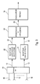
- Figure 3 shows a system for receiving radio signals according to the invention.
- the system for receiving radio signals according to the invention comprises at least one receiver instantaneous broadband 20 delivering a set of radio signal descriptors 22 output for each intercepted signal.
- the radio signal reception system according to the invention comprises at least one narrow-band receiver 21 delivering a set of radio signal descriptors 23 output for each intercepted signal.
- the narrowband receiver 21 may for example be a superheterodyne receiver.
- the set of radio signal descriptors 22 or 23 comprises a pulse descriptor for each pulse present in the radio signal. intercepted.
- a pulse descriptor can include the following information: the level of a pulse with the measurement accuracy, the pulse frequency with the measurement accuracy, the pulse width with the measurement accuracy, the time pulse arrival with measurement accuracy, direction of arrival with measurement accuracy, receiver ID intercepting impulse, polarization of the antenna 10 having intercepted the pulse, the presence or absence of modulation in the pulses.
- the system for receiving radio signals comprises, in particular, a pulse processor 24 receiving as input the radio signal descriptors 22 and 23 coming from the instantaneous broadband receiver 20 and the narrowband receiver 21.
- the pulse processor has in particular, the function of the correlation of the radio-signal descriptors 22 and 23 and the filtering of the radio-signal descriptors 22 and 23.
- the pulse processor has on its output 25 correlated and filtered descriptors of radio signals.
- the correlated and filtered descriptors of radio signals generated by the pulse processor may in particular be directed to a tracking computer 16 performing de-interleaving and tracking to generate tracks for all intercepted radio signals.
- the tracking computer 16 outputs a track for each intercepted radio signal from the same source.
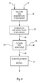
- FIG. 4 shows by a block diagram a method for merging information derived from radioelectric sensors according to the invention. Elements identical to the elements already presented in the preceding figures bear the same references.
- the collection of pulse descriptors 30 is a step of the method according to the invention.
- the pulse descriptors from the set of radio receivers whose information is to be merged by the method according to the invention are received and collected in step 30.
- the collected pulse descriptors may for example be the descriptors of pulses 22 generated by the instantaneous broadband receiver 20 and the pulse descriptors 23 generated by the narrowband receiver 21.
- the step 30 of collecting the pulse descriptors can for example be done continuously in parallel with the other steps of the process according to the invention.
- Figure 4 illustrates the case where two radio receivers provide pulse descriptors. However, the step of collecting pulse descriptors applies to any number of radio receivers.
- the pulse descriptors 22, 23 collected in step 30 are used in another step 32 of the method according to the invention for correlating the pulse descriptors.
- the correlation step 32 of the pulse descriptors compares the different parameters of the pulse descriptors 22, 23 collected. Among the comparison criteria are for example the arrival time of the intercepted pulse, the power level of the pulse, the frequency of the pulse as well as the width of the pulse.
- the pulse descriptors 22 corresponding to the intercepted signal have substantially identical parameters to the pulse descriptors 23 corresponding to the intercepted signal.
- the pulse correlation step 32 eliminates the redundant pulse descriptors 22, 23 and retains only a correlated pulse descriptor 33.
- step 32 of pulse correlation a table taking into account the different comparison states of the parameters contained in the pulse descriptors 22,23 makes it possible to determine which parameter of which pulse descriptor 22,23 is to be stored and transmitted in function of the physical quantities of the intercepted signal.
- the correlated pulse descriptors 33 corresponding to the intercepted signal are transmitted.
- the method according to the invention comprises a step 34 of filtering the pulses.
- Step 34 of pulse filtering receives as input the correlated pulse descriptors 33 coming out of the pulse correlation step 32.
- the purpose of the pulse filtering step 34 is notably to select, according to a certain number of criteria, filtered pulse descriptors 35 and to generate commands to be executed via the output of the commands 36.
- the pulse filtering step 34 comprises in particular a step of marking the pulses.
- a number is assigned to a correlated pulse descriptor 33 if the parameters of said correlated pulse descriptor 33 satisfy the criteria of one or more parameters of a programmed filter.
- This number is a predetermined and known identified number of the method according to the invention. This may be for example a predetermined category of pulses, a sequence number.
- the criteria can include the power level of the pulse, the frequency of the pulse, the width of the pulse and the direction of arrival.
- the pulse filtering step 34 comprises in particular an action triggering step.
- One or more commands are generated on the output of the commands 36 by the method according to the invention if the parameters of one of the correlated pulse descriptors 33 received by the pulse filtering step 34 satisfy the criteria of one or more parameters of a programmed filter.
- the criteria can include the power level of the pulse, the frequency of the pulse, the width of the pulse and the direction of arrival.
- the commands generated there may be mentioned for example a request for additional analysis. This additional analysis request may for example be performed by the narrow-band receiver 21 when the instantaneous broadband receiver 20 has detected the signal described by the correlated descriptor 33 having generated this command.
- the commands generated one can also cite for example a command to an external device.
- the pulse filtering step 34 comprises in particular a step of rejection of pulse descriptors. correlates 33.
- the correlated pulse descriptors 33 whose parameters satisfy the criteria of one or more parameters of a programmed filter are not transmitted.
- the criteria can include the power level of the pulse, the frequency of the pulse, the width of the pulse and the direction of arrival.
- the pulse descriptors generated by the method according to the invention can in particular be transmitted to a step 37 of de-interleaving and tracking.
- This step 37 makes it possible in particular to calculate tracks from the merged information present in the pulse descriptors generated by the method according to the invention.
- the method for melting information derived from radioelectric sensors according to the invention may in particular be implemented by the pulse processor 24.
- the pulse processor may for example be implemented on any device suitable for numerical calculations.
- the generation of pulse descriptors by the radio receivers can be implemented on calculation devices specific to each receiver, on a shared computing device for a certain number of receivers, or on the pulse processor 24.
- the foregoing description assumes the presence of an instant broadband receiver 20 and a narrowband receiver 21.
- the description is applicable to any system having an undetermined number of instant broadband receivers 20 and band receivers.
- the instant broadband receivers 20 and narrowband receivers 21 may be located on the same carrier or on the contrary on different carriers.
- the step of collecting the pulse descriptors 30 receives all the pulse descriptors 22, 23 of the receivers distributed on the different carriers by any means of transmission, for example a radio link.
Abstract
Description
L'invention concerne un procédé de fusion d'informations issues de capteurs radioélectriques. En particulier, l'invention s'applique à l'optimisation de la chaîne d'exploitation des récepteurs large bande instantanée et des récepteurs bande étroite. L'invention a encore pour objet un système de réception radioélectrique.The invention relates to a method of melting information from radio sensors. In particular, the invention applies to the optimization of the operating chain of instant broadband receivers and narrowband receivers. The invention further relates to a radio reception system.
Afin d'assurer la protection des avions, des navires, des drônes ou de tout autre porteur contre les menaces que peuvent représenter les radars hostiles ou les missiles, des systèmes d'autoprotection peuvent être installés à bord. Ils ont notamment pour fonction la détection et l'identification d'émissions radioélectriques, parmi lesquelles figurent les impulsions émises par un radar. Pour remplir ces fonctions, les systèmes d'autoprotection comportent notamment au moins un récepteur radioélectrique adapté à la détection de signaux radioélectriques et un dispositif de traitement des informations provenant du récepteur.In order to protect planes, ships, drones or any other carrier against the threats posed by hostile radars or missiles, self-protection systems may be installed on board. Their functions include the detection and identification of radio transmissions, including the pulses emitted by a radar. To fulfill these functions, the self-protection systems include in particular at least one radio receiver adapted to the detection of radio signals and a device for processing information from the receiver.
La sensibilité d'un récepteur radioélectrique, c'est-à-dire le seuil de puissance à partir duquel un signal radioélectrique est détecté, doit être adaptée au niveau des signaux radioélectriques les plus faibles en puissance que doit détecter le système d'autoprotection. Toutefois, les récepteurs radioélectriques caractérisés par leur grande sensibilité, par exemple les récepteurs superhétérodynes, ne sont capables de détecter les signaux radioélectriques que sur une bande de fréquences limitée, de l'ordre de 1 GHz par exemple. Cette bande de fréquences limitée ne permet pas de couvrir à tout instant la bande de fréquences dans laquelle les impulsions radars peuvent être émises. Il existe cependant des détecteurs couvrant une large bande de fréquences, de l'ordre par exemple de 20GHz, mais dont la sensibilité ne permet pas de détecter les impulsions radars de faible niveau.The sensitivity of a radio receiver, that is the power threshold at which a radio signal is detected, must be adapted to the level of the weakest radio signals to be detected by the tamper system. However, radio receivers characterized by their high sensitivity, for example superheterodyne receivers, are able to detect radio signals only in a limited frequency band, of the order of 1 GHz for example. This limited frequency band does not cover at all times the frequency band in which the radar pulses can be transmitted. There are, however, detectors covering a wide frequency band, of the order of eg 20GHz, but whose sensitivity does not detect low-level radar pulses.
Pour couvrir une large bande de fréquences et détecter les impulsions de faible niveau, les systèmes d'autoprotection utilisent conjointement au moins un récepteur large bande instantanée et un récepteur bande étroite. Chaque récepteur fournit des informations sur son environnement radioélectrique. Le dispositif de traitement des informations utilise notamment ces informations pour générer des pistes pour chaque émetteur intercepté. Une fusion des informations provenant de l'ensemble des récepteurs est alors nécessaire si l'on souhaite disposer d'une vision globale et synthétique de l'environnement radioélectrique du porteur. La fusion des informations produites par les récepteurs s'effectue traditionnellement à partir des pistes calculées par le dispositif de traitement des informations.To cover a broad band of frequencies and detect low-level pulses, the tamper systems jointly use at least one instant broadband receiver and one narrowband receiver. Each receiver provides information about its radio environment. The information processing device notably uses this information to generate tracks for each intercepted transmitter. A fusion of information from all the receivers is then necessary if it is desired to have a global and synthetic view of the carrier's radio environment. The fusion of the information produced by the receivers is traditionally done from the tracks calculated by the information processing device.
Aussi, il est nécessaire de mettre en oeuvre pour chaque récepteur du système d'autoprotection les moyens nécessaires au calcul des pistes. De plus, la vitesse d'adaptation des paramètres du récepteur à bande étroite face à des émissions interceptées par le récepteur large bande est limitée par le temps nécessaire aux calculs des pistes. L'indépendance des récepteurs aboutit de plus à augmenter le poids et les dimensions du système d'autoprotection.Also, it is necessary to implement for each receiver of the self-protection system the means necessary to calculate the tracks. In addition, the speed of adaptation of the parameters of the narrow-band receiver to broadband receiver-intercepted transmissions is limited by the time required to calculate the tracks. The independence of the receivers also results in increasing the weight and dimensions of the self-protection system.
L'invention a notamment pour but de pallier les inconvénients précités. A cet effet, l'invention a pour objet un procédé de fusion d'informations issues de capteurs radioélectriques. Les récepteurs radioélectriques, lorsqu'ils interceptent des signaux radioélectriques, génèrent au moins un descripteur d'impulsions pour chaque impulsion de chaque signal radioélectrique intercepté donné. Les descripteurs d'impulsions comportent un ensemble de caractéristiques propres à une impulsion donnée. Le procédé comporte au moins les étapes suivantes :
- une étape de collecte des descripteurs d'impulsions générés par les récepteurs radioélectriques;
- une étape de corrélation des descripteurs d'impulsions aboutissant à la génération d'un descripteur d'impulsions corrélé pour chaque impulsion de chaque signal radioélectrique intercepté à partir des descripteurs d'impulsions collectés.
- a step of collecting the pulse descriptors generated by the radio receivers;
- a step of correlating the pulse descriptors resulting in the generation of a correlated pulse descriptor for each pulse of each radio signal intercepted from the collected pulse descriptors.
Avantageusement, le procédé selon l'invention comporte une étape de filtrage des descripteurs d'impulsions corrélés par application d'un ou plusieurs filtres, chaque filtre comportant un ensemble de critères.Advantageously, the method according to the invention comprises a step of filtering correlated pulse descriptors by applying one or more filters, each filter comprising a set of criteria.
Dans un mode de réalisation, les caractéristiques d'un descripteur d'impulsions corrélé sont obtenues :
- en comparant les caractéristiques incluses dans les descripteurs d'impulsions générés par les récepteurs radioélectriques ;
- en déterminant à partir des comparaisons les descripteurs d'impulsions décrivant les mêmes impulsions ;
- en sélection pour chaque paramètre le descripteur d'impulsions qui doit fournir ce paramètre.
- le temps d'arrivée de l'impulsion,
- le niveau de puissance de l'impulsion,
- la fréquence de l'impulsion,
- la largeur de l'impulsion.
- comparing the features included in the pulse descriptors generated by the radio receivers;
- by determining from the comparisons the pulse descriptors describing the same pulses;
- selecting for each parameter the pulse descriptor that must provide this parameter.
- the arrival time of the pulse,
- the power level of the pulse,
- the frequency of the pulse,
- the width of the pulse.
Dans un autre mode de réalisation, l'étape de filtrage comporte au moins un filtre qui, lorsque certains paramètres d'un descripteur d'impulsions corrélés satisfont aux critères dudit filtre, ajoute un paramètre au descripteur d'impulsions corrélé correspondant à un numéro prédéterminé et connu du procédé selon l'invention. Les critères du filtre s'appliquent par exemple au moins sur l'un des paramètres d'un descripteur d'impulsions corrélés (33) suivant :
- le niveau de puissance de l'impulsion,
- sur la fréquence de l'impulsion,
- sur la largeur de l'impulsion,
- la direction d'arrivée.
- the power level of the pulse,
- on the frequency of the pulse,
- on the width of the pulse,
- the direction of arrival.
Dans un autre mode de réalisation, l'étape de filtrage comporte au moins un filtre qui, lorsque certains paramètres d'un descripteur d'impulsions corrélés satisfont aux critères dudit filtre, génère une ou plusieurs commandes sur une sortie des commandes. Les critères du filtre s'appliquent par exemple au moins sur l'un des paramètres d'un descripteur d'impulsions corrélés suivant :
- le niveau de puissance de l'impulsion,
- sur la fréquence de l'impulsion,
- sur la largeur de l'impulsion,
- la direction d'arrivée.
- the power level of the pulse,
- on the frequency of the pulse,
- on the width of the pulse,
- the direction of arrival.
Dans un mode de réalisation avantageux, l'étape de filtrage comporte au moins un filtre qui, lorsque certains paramètres d'un descripteur d'impulsions corrélés satisfont aux critères dudit filtre, supprime le descripteur d'impulsions corrélé. Les critères du filtre s'appliquent par exemple au moins sur l'un des paramètres d'un descripteur d'impulsions corrélés suivant :
- le niveau de puissance de l'impulsion,
- sur la fréquence de l'impulsion,
- sur la largeur de l'impulsion,
- la direction d'arrivée.
- the power level of the pulse,
- on the frequency of the pulse,
- on the width of the pulse,
- the direction of arrival.
En outre, l'invention a encore pour objet un système de réception radioélectrique comportant au moins un récepteur radioélectrique large bande instantanée et un récepteur radioélectrique bande étroite, au moins un processeur d'impulsions. Le récepteur radioélectrique large bande instantanée lorsqu'il intercepte des signaux radioélectriques génèrent au moins un descripteur d'impulsions pour chaque impulsion de chaque signal radioélectrique intercepté donné. Le récepteur radioélectrique bande étroite lorsqu'il intercepte des signaux radioélectriques génèrent au moins un descripteur d'impulsions pour chaque impulsion de chaque signal radioélectrique intercepté donné. Le processeur d'impulsions est adapté à :
- la collecte des descripteurs d'impulsions générés par le récepteur radioélectrique large bande instantanée et le récepteur radioélectrique large bande étroite;
- la corrélation des descripteurs d'impulsions aboutissant à la génération d'un descripteur d'impulsions corrélé pour chaque impulsion de chaque signal radioélectrique intercepté à partir des descripteurs d'impulsions collectés.
- collecting the pulse descriptors generated by the instantaneous broadband radio receiver and the narrowband radio receiver;
- the correlation of the pulse descriptors resulting in the generation of a correlated pulse descriptor for each pulse of each radio signal intercepted from the collected pulse descriptors.
L'invention a notamment pour avantages qu'elle permet de déclencher des actions adaptées dans un délai optimum après la détection d'un signal radioélectrique. Elle permet de plus d'optimiser l'emploi du récepteur bande étroite en limitant son utilisation au cas où le récepteur large bande instantanée ne permet pas de caractériser assez finement le signal radioélectrique.The advantages of the invention include that it makes it possible to trigger adapted actions in an optimum time after the detection of a radio signal. Moreover, it makes it possible to optimize the use of the narrow-band receiver by limiting its use in the case where the instantaneous broadband receiver does not allow the radio signal to be characterized quite finely.
D'autres caractéristiques et avantages de l'invention apparaîtront à l'aide de la description qui suit faite en regard des dessins annexés qui représentent :
- la figure 1, un diagramme représentant la sensibilité et la bande de fréquences utile pour un récepteur large bande instantanée et un récepteur bande étroite ;
- la figure 2, un système de réception de signaux radioélectriques selon l'état de l'art ;
- la figure 3, un système de réception de signaux radioélectriques selon l'invention ;
- la figure 4, un procédé de fusion d'informations issues de capteurs radioélectriques selon l'invention.
- FIG. 1, a diagram showing the sensitivity and the useful frequency band for an instant broadband receiver and a narrowband receiver;
- Figure 2, a system for receiving radio signals according to the state of the art;
- FIG. 3, a system for receiving radio signals according to the invention;
- FIG. 4, a method of fusing information derived from radioelectric sensors according to the invention.
La figure 1 est un diagramme représentant la sensibilité et la bande de fréquences utile pour un récepteur large bande instantanée et un récepteur bande étroite. Les signaux radioélectriques, comme par exemple les impulsions émises par un radar, ont notamment pour grandeur physique leur fréquence ainsi que leur niveau de puissance. Selon l'émetteur des signaux radioélectriques, la différence de fréquence entre deux signaux radioélectriques peut sensiblement atteindre 20GHz. Les récepteurs radioélectriques ont notamment pour fonction l'interception de signaux radioélectriques et la mesure des grandeurs physiques qui les caractérisent. Parmi les différents types de récepteurs radioélectriques, on appelle récepteur large bande instantanée, les récepteurs capables d'intercepter et de mesurer les signaux radioélectriques dans une large plage de fréquences, pouvant atteindre par exemple 20 GHz. Les récepteurs radioélectriques large bande instantanée sont suffisamment sensibles pour détecter des signaux radioélectriques dont le niveau est supérieur à -50 décibels milliwatts isotropiques environ. Il existe un second type de récepteurs radioélectriques appelé récepteur bande étroite, dont les récepteurs superhétérodynes font notamment partie. Les récepteurs bande étroite sont capables d'intercepter et de mesurer les signaux radioélectriques dans une plage de fréquences pouvant atteindre par exemple 1 GHz. En contrepartie de leur plage de fréquences réduite par rapport à un récepteur large bande instantanée, le niveau de puissance le plus faible du signal radioélectrique que ces détecteurs bande étroite sont capables d'intercepter et de mesurer est de l'ordre de -75 décibels milliwatts isotropiques.Fig. 1 is a diagram showing the sensitivity and the useful frequency band for an instant broadband receiver and a narrowband receiver. The radio signals, such as for example the pulses emitted by a radar, have in particular for their physical size their frequency as well as their power level. Depending on the transmitter of the radio signals, the difference in frequency between two radio signals can reach substantially 20GHz. One of the functions of the radio receivers is the interception of radio signals and the measurement of the physical quantities that characterize them. Among the different types of radio receivers, instantaneous broadband receivers are called receivers capable of intercepting and measuring radio signals in a wide frequency range, for example up to 20 GHz. Instantaneous broadband radio receivers are sensitive enough to detect radio signals whose level is greater than approximately -50 decibels isotropic milliwatts. There is a second type of radio receiver called narrowband receiver, including superheterodyne receivers are included. Narrow band receivers are capable of intercepting and measuring radio signals in a frequency range up to 1 GHz, for example. In return for their reduced frequency range compared to an instant broadband receiver, the lowest power level of the radio signal that these narrowband detectors are capable of intercepting and measuring is of the order of -75 decibels milliwatts isotropic.
On revient à la figure 1. Le diagramme comporte un axe des abscisses 2 indiquant la fréquence en gigahertz des signaux radioélectriques. L'axe des abscisses 2 est échelonné de 0 à 20 GHz. Le diagramme comporte un axe des ordonnées 1 indiquant le niveau du signal reçu par le radar exprimé en décibel milliwatt isotropique. L'axe des ordonnées 1 est échelonné de 0 à -80 décibels milliwatts isotropiques. Une surface rectangulaire 3 représente l'ensemble des signaux radioélectriques caractérisés par leur fréquence et leur niveau qu'un récepteur large bande instantanée est capable instantanément d'intercepter et de mesurer. La bande de fréquences LLB qu'est capable de couvrir un récepteur large bande instantanée est de l'ordre de 20 GHz. Le seuil SLB en dessous duquel la puissance d'un signal radioélectrique est trop faible pour être intercepter et mesurer par un récepteur large bande instantanée est de l'ordre de -50 décibels milliwatts isotropiques. Une surface rectangulaire 4 représente l'ensemble des signaux radioélectriques caractérisés par leur fréquence et leur niveau qu'un récepteur bande étroite est capable instantanément d'intercepter et de mesurer. La bande de fréquences LBE qu'est capable de couvrir un récepteur bande étroite est de l'ordre de 1 GHz. La fréquence centrale FC du récepteur bande étroite permet de déterminer la fréquence des signaux radioélectriques qui peuvent être instantanément interceptés et mesurés : il s'agit des signaux radioélectriques dont la fréquence est comprise entre ![]()
![]()
![]()
![]()
Aussi dans le cas d'un système d'autoprotection, dont la fonction d'écoute nécessite la mise en oeuvre de récepteurs radioélectriques, l'ensemble des signaux radioélectriques provenant notamment des radars ne peut être intercepté et mesuré instantanément par un seul type de récepteur radioélectrique. En effet, les impulsions produites par deux radars distincts présents dans l'environnement d'un porteur peuvent par exemple être distantes de 20 GHz. De plus, les impulsions générées par un radar rotatif par exemple peuvent avoir un niveau de l'ordre de -75 décibels milliwatts isotropiques, voire inférieure.Also in the case of a self-protection system, whose listening function requires the implementation of radio receivers, all of the radio signals, including radars can not be intercepted and measured instantly by a single type of receiver radio. Indeed, the pulses produced by two distinct radars present in the environment of a carrier may for example be 20 GHz apart. In addition, the pulses generated by a rotary radar for example may have a level of the order of -75 decibels isotropic milliwatts or lower.
La figure 2 illustre un système de réception de signaux radioélectriques selon l'état de l'art. Le système de réception de signaux radioélectriques a notamment pour fonction l'interception et le pistage de signaux radioélectriques, parmi lesquelles figurent les impulsions émises par un radar ou encore les émissions d'un système de communication. Le système de réception de signaux radioélectriques selon l'état de l'art comporte notamment des antennes réceptrices 10 reliées à une matrice radiofréquence 11. Les signaux collectés 12 sont transmis d'une part à un récepteur large bande instantanée 13 et d'autre part à un récepteur bande étroite 14. Le récepteur large bande instantanée 13 délivre en sortie des informations sur les signaux radioélectriques qu'il a interceptés et mesurés. De même, le récepteur bande étroite 14 délivre en sortie des informations sur les signaux radioélectriques qu'il a interceptés et mesurés. Les informations issues du récepteur large bande instantanée 13 sont transmises à un calculateur de pistage 16. On appelle piste l'ensemble des informations sur une période donnée caractérisant un signal radioélectrique provenant d'une même source émettrice. Le calculateur de pistage 16 génère des pistes 18 à partir des informations envoyées par le récepteur large bande instantanée 13. De même, les informations issues du récepteur bande étroite 13 sont transmises à un calculateur de pistage 17. Le calculateur de pistage 17 génère des pistes 18 à partir des informations envoyées par le récepteur bande étroite 13.Figure 2 illustrates a system for receiving radio signals according to the state of the art. The signal reception system In particular, the function of radio communications is the interception and tracking of radio signals, which include pulses emitted by a radar or transmissions from a communication system. The system for receiving radio signals according to the state of the art notably comprises receiving
Si l'on se réfère à la figure 1, on distingue trois cas de figure. Le premier correspond au cas où un signal radioélectrique se situant dans la surface rectangulaire 3 mais pas dans la surface rectangulaire 5 n'est intercepté que par le récepteur large bande instantanée 13. Dans ce cas, seul le calculateur de pistage 16 recevant ses informations du récepteur large bande instantanée 13 génère une piste 18. Le second correspond au cas où un signal radioélectrique se situant dans la surface rectangulaire 4 mais pas dans la surface rectangulaire 5 n'est intercepté que par le récepteur bande étroite 14. Dans ce cas, seul le calculateur de pistage 17 recevant ses informations du récepteur bande étroite 14 génère une piste 18. Le troisième correspond au cas où un signal radioélectrique se situant dans la surface rectangulaire 5 est intercepté à la fois par le récepteur large bande instantanée 13 et par le récepteur bande étroite 14. Dans ce cas, les calculateurs de pistage 16 et 17 génèrent tous les deux une piste 18. Il existe donc des cas où pour une même source émettrice deux pistes 18 sont générés par les calculateurs de pistage 16 et 17. Les pistes 18 sont donc transmises à un dispositif de corrélation des pistes 19. Les pistes 18 redondantes sont supprimées par le dispositif de corrélation des pistes 19. Le dispositif de corrélation des pistes 19 délivre en sortie des pistes corrélées.If we refer to Figure 1, we distinguish three scenarios. The first corresponds to the case where a radio signal lying in the
La figure 3 montre un système de réception de signaux radioélectriques selon l'invention. Les éléments identiques aux éléments déjà présentés à la figure 2 portent les mêmes références. A la différence du récepteur large bande du système de réception de signaux radioélectriques selon l'état de l'art illustré par la figure 2 qui délivre en sortie des pistes, le système de réception de signaux radioélectriques selon l'invention comporte au moins un récepteur large bande instantanée 20 délivrant un ensemble de descripteurs de signaux radioélectriques 22 en sortie pour chaque signal intercepté. De même, à la différence du récepteur bande étroite du système de réception de signaux radioélectriques selon l'état de l'art illustré par la figure 2 qui délivre en sortie des pistes, le système de réception de signaux radioélectriques selon l'invention comporte au moins un récepteur bande étroite 21 délivrant un ensemble de descripteurs de signaux radioélectriques 23 en sortie pour chaque signal intercepté. Le récepteur bande étroite 21 peut par exemple être un récepteur superhétérodyne.Figure 3 shows a system for receiving radio signals according to the invention. The elements identical to the elements already presented in FIG. 2 bear the same references. Unlike the broadband receiver of the radio signal reception system according to the state of the art illustrated in FIG. 2 which outputs tracks, the system for receiving radio signals according to the invention comprises at least one receiver
Dans le cas d'un signal radioélectrique comportant une série d'impulsions, comme par exemple le signal émis par un radar, l'ensemble de descripteurs de signaux radioélectriques 22 ou 23 comporte un descripteur d'impulsions pour chaque impulsion présente dans le signal radioélectrique intercepté.In the case of a radio signal comprising a series of pulses, such as for example the signal transmitted by a radar, the set of
Un descripteur d'impulsions peut notamment comporter les informations suivantes : le niveau d'une impulsion avec la précision de mesure, la fréquence de l'impulsion avec la précision de mesure, la largeur de l'impulsion avec la précision de mesure, le temps d'arrivée de l'impulsion avec la précision de mesure, la direction d'arrivée avec la précision de mesure, l'identifiant du récepteur ayant intercepté l'impulsion, la polarisation de l'antenne 10 ayant interceptée l'impulsion, la présence ou non de modulation dans les impulsions.A pulse descriptor can include the following information: the level of a pulse with the measurement accuracy, the pulse frequency with the measurement accuracy, the pulse width with the measurement accuracy, the time pulse arrival with measurement accuracy, direction of arrival with measurement accuracy, receiver ID intercepting impulse, polarization of the
Le système de réception de signaux radioélectriques selon l'invention comporte notamment un processeur d'impulsions 24 recevant en entrée les descripteurs de signaux radioélectriques 22 et 23 provenant du récepteur large bande instantanée 20 et du récepteur bande étroite 21. Le processeur d'impulsions a notamment pour fonction la corrélation des descripteurs de signaux radioélectriques 22 et 23 et le filtrage des descripteurs de signaux radioélectriques 22 et 23. Le processeur d'impulsions présente sur sa sortie 25 des descripteurs corrélés et filtrés de signaux radioélectriques.The system for receiving radio signals according to the invention comprises, in particular, a
Les descripteurs corrélés et filtrés de signaux radioélectriques 25 générés par le processeur d'impulsions peuvent notamment être dirigée vers un calculateur de pistage 16 réalisant le dé-entrelacement et le pistage afin de générer des pistes pour l'ensemble des signaux radioélectriques interceptés. Le calculateur de pistage 16 délivre en sortie une piste pour chaque signal radioélectrique intercepté provenant d'une même source.The correlated and filtered descriptors of radio signals generated by the pulse processor may in particular be directed to a tracking
La figure 4 montre par un synoptique un procédé de fusion d'informations issues de capteurs radioélectriques selon l'invention. Les éléments identiques aux éléments déjà présentés aux figures précédentes portent les mêmes références. La collecte des descripteurs d'impulsions 30 est une étape du procédé selon l'invention. Les descripteurs d'impulsions provenant de l'ensemble des récepteurs radioélectriques dont les informations doivent être fusionnées par le procédé selon l'invention sont reçus et collectés à l'étape 30. Les descripteurs d'impulsions collectés peuvent par exemple être les descripteurs d'impulsions 22 générés par le récepteur large bande instantanée 20 et les descripteurs d'impulsions 23 générés par le récepteur bande étroite 21. L'étape 30 de collecte des descripteurs d'impulsions peut par exemple se faire de façon continue en parallèle des autres étapes du procédé selon l'invention. La figure 4 illustre le cas où deux récepteurs radioélectriques fournissent des descripteurs d'impulsions. Cependant, l'étape de collecte des descripteurs d'impulsions 30 s'applique à un nombre quelconque de récepteurs radioélectriques.FIG. 4 shows by a block diagram a method for merging information derived from radioelectric sensors according to the invention. Elements identical to the elements already presented in the preceding figures bear the same references. The collection of
Les descripteurs d'impulsions 22, 23 collectés à l'étape 30 sont utilisés dans une autre étape 32 du procédé selon l'invention de corrélation des descripteurs d'impulsions. L'étape 32 de corrélation des descripteurs d'impulsions compare les différents paramètres des descripteurs d'impulsions 22, 23 collectés. Parmi les critères de comparaison figurent par exemple le temps d'arrivée de l'impulsion interceptée, le niveau de puissance de l'impulsion, la fréquence de l'impulsion ainsi que la largeur de l'impulsion. Lorsqu'un signal radioélectrique est intercepté et mesuré à la fois par le récepteur large bande instantanée 20 et par le récepteur bande étroite 21, les descripteurs d'impulsions 22 correspondant au signal intercepté ont des paramètres sensiblement identiques aux descripteurs d'impulsions 23 correspondant au signal intercepté. Après les comparaisons des descripteurs d'impulsions 22, 23, il est alors possible d'identifier les descripteurs d'impulsions 22, 23 décrivant les mêmes impulsions. Dans ce cas de figure, l'étape 32 de corrélation des impulsions élimine les descripteurs d'impulsions 22, 23 redondants, et ne conserve qu'un descripteur d'impulsions corrélé 33.The pulse descriptors 22, 23 collected in
Toutefois, la caractérisation des grandeurs physiques des signaux radioélectriques n'atteint pas la même précision si les signaux radioélectriques sont interceptés par le récepteur large bande instantanée 13 ou par le récepteur bande étroite 14. C'est pourquoi, dans un mode de réalisation de l'étape 32 de corrélation des impulsions, une table prenant en compte les différents états de comparaison des paramètres figurant dans les descripteurs d'impulsions 22,23 permet de déterminer quel paramètre de quel descripteur d'impulsions 22,23 doit être conservé et transmis en fonction des grandeurs physiques du signal intercepté.However, the characterization of the physical quantities of the radio signals does not reach the same accuracy if the radio signals are intercepted by the
Lorsqu'un signal radioélectrique est intercepté et mesuré par un seul des récepteurs large bande instantanée 20 et bande étroite 21, les descripteurs d'impulsions corrélés 33 correspondant au signal intercepté sont transmis.When a radio signal is intercepted and measured by only one of the instant broadband and
Dans un mode de réalisation avantageux, le procédé selon l'invention comporte une étape 34 de filtrage des impulsions. L'étape 34 de filtrage des impulsions reçoit en entrée les descripteurs d'impulsions corrélés 33 sortant de l'étape 32 de corrélation des impulsions. L'étape 34 de filtrage des impulsions a notamment pour fonction de sélectionner selon un certain nombre de critères des descripteurs d'impulsions filtrés 35 et de générer des commandes à exécuter via la sortie des commandes 36.In an advantageous embodiment, the method according to the invention comprises a
Dans un mode de réalisation, l'étape 34 de filtrage des impulsions comporte notamment une étape de marquage des impulsions. Un numéro est attribué à un descripteur d'impulsions corrélé 33 si les paramètres dudit descripteur d'impulsions corrélé 33 satisfont aux critères d'un ou plusieurs paramètres d'un filtre programmé. Ce numéro est un numéro identifié prédéterminé et connu du procédé selon l'invention. Il peut s'agir par exemple d'une catégorie prédéterminée d'impulsions, d'un numéro de séquence. Les critères peuvent notamment porter sur le niveau de puissance de l'impulsion, sur la fréquence de l'impulsion, sur la largeur de l'impulsion ainsi que sur la direction d'arrivée.In one embodiment, the
Dans un mode de réalisation, l'étape 34 de filtrage des impulsions comporte notamment une étape de déclenchement d'action. Une ou plusieurs commandes sont générées sur la sortie des commandes 36 par le procédé selon l'invention si les paramètres d'un des descripteurs d'impulsions corrélés 33 reçus par l'étape 34 de filtrage des impulsions satisfont aux critères d'un ou plusieurs paramètres d'un filtre programmé. Les critères peuvent notamment porter sur le niveau de puissance de l'impulsion, sur la fréquence de l'impulsion, sur la largeur de l'impulsion ainsi que sur la direction d'arrivée. Parmi les commandes générées, on peut citer par exemple une demande d'analyse complémentaire. Cette demande d'analyse complémentaire peut par exemple être effectuée par le récepteur bande étroite 21 lorsque le récepteur large bande instantanée 20 a détecté le signal décrit par le descripteur corrélé 33 ayant engendré cette commande. Parmi les commandes générées, on peut encore citer par exemple une commande vers un dispositif externe.In one embodiment, the
Dans un mode de réalisation, l'étape 34 de filtrage des impulsions comporte notamment une étape de réjection de descripteurs d'impulsions corrélés 33. Les descripteurs d'impulsions corrélés 33 dont les paramètres satisfont aux critères d'un ou plusieurs paramètres d'un filtre programmé ne sont pas transmis. Les critères peuvent notamment porter sur le niveau de puissance de l'impulsion, sur la fréquence de l'impulsion, sur la largeur de l'impulsion ainsi que sur la direction d'arrivée.In one embodiment, the
Dans un mode de réalisation, les descripteurs d'impulsions générés par le procédé selon l'invention peuvent notamment être transmis à une étape 37 de dé-entrelacement et de pistage. Cette étape 37 permet notamment de calculer des pistes à partir des informations fusionnées présentes dans les descripteurs d'impulsions générés par le procédé selon l'invention.In one embodiment, the pulse descriptors generated by the method according to the invention can in particular be transmitted to a step 37 of de-interleaving and tracking. This step 37 makes it possible in particular to calculate tracks from the merged information present in the pulse descriptors generated by the method according to the invention.
Le procédé de fusion d'informations issues de capteurs radioélectriques selon l'invention peut notamment être mis en oeuvre par le processeur d'impulsions 24. Le processeur d'impulsion peut par exemple être implémenté sur un dispositif quelconque adapté aux calculs numériques.The method for melting information derived from radioelectric sensors according to the invention may in particular be implemented by the
La génération de descripteurs d'impulsions par les récepteurs radioélectriques peut être implémentée sur des dispositifs de calculs propres à chaque récepteur, sur un dispositif de calculs mutualisé pour un certain nombre de récepteurs, ou encore sur le processeur d'impulsions 24.The generation of pulse descriptors by the radio receivers can be implemented on calculation devices specific to each receiver, on a shared computing device for a certain number of receivers, or on the
La description précédente fait l'hypothèse de la présence d'un récepteur large bande instantanée 20 et d'un récepteur bande étroite 21. Toutefois, la description est applicable à tout système comportant un nombre indéterminé de récepteurs large bande instantanée 20 et de récepteurs bande étroite 21. De même, les récepteurs large bande instantanée 20 et de récepteurs bande étroite 21 peuvent être situées sur un même porteur ou au contraire sur des porteurs différents. Dans ce dernier cas, l'étape de collecte des descripteurs d'impulsion 30 reçoit tous les descripteurs d'impulsions 22, 23 des récepteurs répartis sur les différents porteurs par un moyen de transmission quelconque, par exemple une liaison radio.The foregoing description assumes the presence of an
Claims (24)
Applications Claiming Priority (1)
| Application Number | Priority Date | Filing Date | Title |
|---|---|---|---|
| FR0507143A FR2888426B1 (en) | 2005-07-05 | 2005-07-05 | METHOD OF MERGING INFORMATION FROM RADIO RECEIVERS AND RADIO RECEIVING DEVICE |
Publications (2)
| Publication Number | Publication Date |
|---|---|
| EP1742376A1 true EP1742376A1 (en) | 2007-01-10 |
| EP1742376B1 EP1742376B1 (en) | 2009-12-30 |
Family
ID=36021770
Family Applications (1)
| Application Number | Title | Priority Date | Filing Date |
|---|---|---|---|
| EP06116497A Active EP1742376B1 (en) | 2005-07-05 | 2006-07-03 | Information fusion method for informations coming from radio receivers and radioelectrical reception device |
Country Status (5)
| Country | Link |
|---|---|
| EP (1) | EP1742376B1 (en) |
| AT (1) | ATE453964T1 (en) |
| DE (1) | DE602006011394D1 (en) |
| ES (1) | ES2338034T3 (en) |
| FR (1) | FR2888426B1 (en) |
Cited By (3)
| Publication number | Priority date | Publication date | Assignee | Title |
|---|---|---|---|---|
| WO2009013314A1 (en) * | 2007-07-24 | 2009-01-29 | Thales | Method for intercepting radioelectric signals and instantaneous broadband compact receiver |
| KR101427804B1 (en) * | 2012-09-25 | 2014-08-07 | 국방과학연구소 | Digital receiver and signal processing method thereof |
| EP4009068A1 (en) * | 2020-12-04 | 2022-06-08 | Avantix SAS | System and method for intercepting non-discursive electromagnetic signals emitted in a wide frequency band |
Families Citing this family (1)
| Publication number | Priority date | Publication date | Assignee | Title |
|---|---|---|---|---|
| KR101326096B1 (en) | 2012-05-18 | 2013-11-07 | 국방과학연구소 | Pdw data detection and preprocessing method for recognizing intra-pulse modulation |
Citations (4)
| Publication number | Priority date | Publication date | Assignee | Title |
|---|---|---|---|---|
| US4025920A (en) * | 1972-09-28 | 1977-05-24 | Westinghouse Electric Corporation | Identification of radar systems |
| EP0012119A1 (en) * | 1978-11-30 | 1980-06-11 | SELENIA INDUSTRIE ELETTRONICHE ASSOCIATE S.p.A. | Automatic radar emission extractor |
| US5963653A (en) * | 1997-06-19 | 1999-10-05 | Raytheon Company | Hierarchical information fusion object recognition system and method |
| US20030179084A1 (en) * | 2002-03-21 | 2003-09-25 | Ford Global Technologies, Inc. | Sensor fusion system architecture |
-
2005
- 2005-07-05 FR FR0507143A patent/FR2888426B1/en not_active Expired - Fee Related
-
2006
- 2006-07-03 AT AT06116497T patent/ATE453964T1/en not_active IP Right Cessation
- 2006-07-03 ES ES06116497T patent/ES2338034T3/en active Active
- 2006-07-03 EP EP06116497A patent/EP1742376B1/en active Active
- 2006-07-03 DE DE602006011394T patent/DE602006011394D1/en active Active
Patent Citations (4)
| Publication number | Priority date | Publication date | Assignee | Title |
|---|---|---|---|---|
| US4025920A (en) * | 1972-09-28 | 1977-05-24 | Westinghouse Electric Corporation | Identification of radar systems |
| EP0012119A1 (en) * | 1978-11-30 | 1980-06-11 | SELENIA INDUSTRIE ELETTRONICHE ASSOCIATE S.p.A. | Automatic radar emission extractor |
| US5963653A (en) * | 1997-06-19 | 1999-10-05 | Raytheon Company | Hierarchical information fusion object recognition system and method |
| US20030179084A1 (en) * | 2002-03-21 | 2003-09-25 | Ford Global Technologies, Inc. | Sensor fusion system architecture |
Cited By (4)
| Publication number | Priority date | Publication date | Assignee | Title |
|---|---|---|---|---|
| WO2009013314A1 (en) * | 2007-07-24 | 2009-01-29 | Thales | Method for intercepting radioelectric signals and instantaneous broadband compact receiver |
| FR2919447A1 (en) * | 2007-07-24 | 2009-01-30 | Thales Sa | METHOD OF INTERCEPTING RADIO SIGNALS AND INSTANT BROADBAND COMPACT RECEIVER |
| KR101427804B1 (en) * | 2012-09-25 | 2014-08-07 | 국방과학연구소 | Digital receiver and signal processing method thereof |
| EP4009068A1 (en) * | 2020-12-04 | 2022-06-08 | Avantix SAS | System and method for intercepting non-discursive electromagnetic signals emitted in a wide frequency band |
Also Published As
| Publication number | Publication date |
|---|---|
| EP1742376B1 (en) | 2009-12-30 |
| ATE453964T1 (en) | 2010-01-15 |
| FR2888426A1 (en) | 2007-01-12 |
| DE602006011394D1 (en) | 2010-02-11 |
| ES2338034T3 (en) | 2010-05-03 |
| FR2888426B1 (en) | 2010-09-03 |
Similar Documents
| Publication | Publication Date | Title |
|---|---|---|
| EP0755524B1 (en) | Traffic monitoring method for the automatic detection of vehicle-related incidents | |
| EP2368135A1 (en) | Method for filtering the radar echoes produced by wind turbines | |
| EP2869085B1 (en) | Method for detecting interference in a satellite radio-navigation signal by detecting a deformation of the correlation function | |
| EP1671152B1 (en) | Method and device for filtering replies in a secondary radar extractor | |
| EP1742376B1 (en) | Information fusion method for informations coming from radio receivers and radioelectrical reception device | |
| EP0560658B1 (en) | Method and device for garble detection of an SSR via phase analysis | |
| WO2006008227A1 (en) | Cfar method by statistical segmentation and normalisation | |
| FR2916538A1 (en) | INTERFERENCE PROCESSING OF A RADIO FREQUENCY SIGNAL BY POWER INVERSION | |
| EP2469707B1 (en) | Automatic gain control device for satellite positioning receivers | |
| EP3361285B1 (en) | System for detecting personal gnss jammers | |
| EP1998441A2 (en) | Automatic control of gain based on the density of probability of power received | |
| JP3878103B2 (en) | Intrusion detection device | |
| CA2439563A1 (en) | Device and method for the suppression of pulsed wireless signals | |
| EP0048200B1 (en) | Tuning-frequency search device for a frequency-modulation radio receiver | |
| EP4009068B1 (en) | System and method for intercepting non-discursive electromagnetic signals emitted in a wide frequency band | |
| EP1058402B1 (en) | Method for processing an impulse signal with an adaptive threshold and corresponding receiver | |
| EP2017642B1 (en) | Method for detecting and measuring parameters of radioelectric signals | |
| EP3400457B1 (en) | Method for deleting a signal coming from an on-board radar | |
| FR2998973A1 (en) | Method for determining characteristics of radar signal in presence of interferences for electromagnetic environmental monitoring application, involves eliminating values of differences in times of arrival that are out of agility fields | |
| FR2581765A1 (en) | Electromagnetic system for measuring short distances | |
| EP0891049A1 (en) | Method for the estimation of the angular spread of a signal transmitted from a transmitter to a receiver and corresponding receiver | |
| EP4050376A1 (en) | Radar proximity imaging system with multi-channel antenna | |
| FR3120133A1 (en) | NAVIGATION DURING A DEFAULT OPERATION OF A SATELLITE SIGNAL RECEIVER | |
| WO2019093871A1 (en) | Method for detecting the reception state of a gnss signal | |
| FR2634902A1 (en) | Radar transponder |
Legal Events
| Date | Code | Title | Description |
|---|---|---|---|
| PUAI | Public reference made under article 153(3) epc to a published international application that has entered the european phase |
Free format text: ORIGINAL CODE: 0009012 |
|
| AK | Designated contracting states |
Kind code of ref document: A1 Designated state(s): AT BE BG CH CY CZ DE DK EE ES FI FR GB GR HU IE IS IT LI LT LU LV MC NL PL PT RO SE SI SK TR |
|
| AX | Request for extension of the european patent |
Extension state: AL BA HR MK YU |
|
| 17P | Request for examination filed |
Effective date: 20070614 |
|
| 17Q | First examination report despatched |
Effective date: 20070712 |
|
| AKX | Designation fees paid |
Designated state(s): AT BE BG CH CY CZ DE DK EE ES FI FR GB GR HU IE IS IT LI LT LU LV MC NL PL PT RO SE SI SK TR |
|
| GRAP | Despatch of communication of intention to grant a patent |
Free format text: ORIGINAL CODE: EPIDOSNIGR1 |
|
| GRAS | Grant fee paid |
Free format text: ORIGINAL CODE: EPIDOSNIGR3 |
|
| GRAA | (expected) grant |
Free format text: ORIGINAL CODE: 0009210 |
|
| AK | Designated contracting states |
Kind code of ref document: B1 Designated state(s): AT BE BG CH CY CZ DE DK EE ES FI FR GB GR HU IE IS IT LI LT LU LV MC NL PL PT RO SE SI SK TR |
|
| REG | Reference to a national code |
Ref country code: GB Ref legal event code: FG4D Free format text: NOT ENGLISH |
|
| REG | Reference to a national code |
Ref country code: CH Ref legal event code: EP |
|
| REG | Reference to a national code |
Ref country code: IE Ref legal event code: FG4D |
|
| REF | Corresponds to: |
Ref document number: 602006011394 Country of ref document: DE Date of ref document: 20100211 Kind code of ref document: P |
|
| REG | Reference to a national code |
Ref country code: SE Ref legal event code: TRGR |
|
| PG25 | Lapsed in a contracting state [announced via postgrant information from national office to epo] |
Ref country code: LT Free format text: LAPSE BECAUSE OF FAILURE TO SUBMIT A TRANSLATION OF THE DESCRIPTION OR TO PAY THE FEE WITHIN THE PRESCRIBED TIME-LIMIT Effective date: 20091230 Ref country code: FI Free format text: LAPSE BECAUSE OF FAILURE TO SUBMIT A TRANSLATION OF THE DESCRIPTION OR TO PAY THE FEE WITHIN THE PRESCRIBED TIME-LIMIT Effective date: 20091230 |
|
| REG | Reference to a national code |
Ref country code: ES Ref legal event code: FG2A Ref document number: 2338034 Country of ref document: ES Kind code of ref document: T3 |
|
| REG | Reference to a national code |
Ref country code: NL Ref legal event code: VDEP Effective date: 20091230 |
|
| LTIE | Lt: invalidation of european patent or patent extension |
Effective date: 20091230 |
|
| PG25 | Lapsed in a contracting state [announced via postgrant information from national office to epo] |
Ref country code: SI Free format text: LAPSE BECAUSE OF FAILURE TO SUBMIT A TRANSLATION OF THE DESCRIPTION OR TO PAY THE FEE WITHIN THE PRESCRIBED TIME-LIMIT Effective date: 20091230 Ref country code: LV Free format text: LAPSE BECAUSE OF FAILURE TO SUBMIT A TRANSLATION OF THE DESCRIPTION OR TO PAY THE FEE WITHIN THE PRESCRIBED TIME-LIMIT Effective date: 20091230 Ref country code: PL Free format text: LAPSE BECAUSE OF FAILURE TO SUBMIT A TRANSLATION OF THE DESCRIPTION OR TO PAY THE FEE WITHIN THE PRESCRIBED TIME-LIMIT Effective date: 20091230 |
|
| PG25 | Lapsed in a contracting state [announced via postgrant information from national office to epo] |
Ref country code: AT Free format text: LAPSE BECAUSE OF FAILURE TO SUBMIT A TRANSLATION OF THE DESCRIPTION OR TO PAY THE FEE WITHIN THE PRESCRIBED TIME-LIMIT Effective date: 20091230 |
|
| REG | Reference to a national code |
Ref country code: IE Ref legal event code: FD4D |
|
| PG25 | Lapsed in a contracting state [announced via postgrant information from national office to epo] |
Ref country code: EE Free format text: LAPSE BECAUSE OF FAILURE TO SUBMIT A TRANSLATION OF THE DESCRIPTION OR TO PAY THE FEE WITHIN THE PRESCRIBED TIME-LIMIT Effective date: 20091230 Ref country code: PT Free format text: LAPSE BECAUSE OF FAILURE TO SUBMIT A TRANSLATION OF THE DESCRIPTION OR TO PAY THE FEE WITHIN THE PRESCRIBED TIME-LIMIT Effective date: 20100430 Ref country code: RO Free format text: LAPSE BECAUSE OF FAILURE TO SUBMIT A TRANSLATION OF THE DESCRIPTION OR TO PAY THE FEE WITHIN THE PRESCRIBED TIME-LIMIT Effective date: 20091230 Ref country code: IS Free format text: LAPSE BECAUSE OF FAILURE TO SUBMIT A TRANSLATION OF THE DESCRIPTION OR TO PAY THE FEE WITHIN THE PRESCRIBED TIME-LIMIT Effective date: 20100430 Ref country code: BG Free format text: LAPSE BECAUSE OF FAILURE TO SUBMIT A TRANSLATION OF THE DESCRIPTION OR TO PAY THE FEE WITHIN THE PRESCRIBED TIME-LIMIT Effective date: 20100330 Ref country code: NL Free format text: LAPSE BECAUSE OF FAILURE TO SUBMIT A TRANSLATION OF THE DESCRIPTION OR TO PAY THE FEE WITHIN THE PRESCRIBED TIME-LIMIT Effective date: 20091230 |
|
| PG25 | Lapsed in a contracting state [announced via postgrant information from national office to epo] |
Ref country code: CZ Free format text: LAPSE BECAUSE OF FAILURE TO SUBMIT A TRANSLATION OF THE DESCRIPTION OR TO PAY THE FEE WITHIN THE PRESCRIBED TIME-LIMIT Effective date: 20091230 Ref country code: SK Free format text: LAPSE BECAUSE OF FAILURE TO SUBMIT A TRANSLATION OF THE DESCRIPTION OR TO PAY THE FEE WITHIN THE PRESCRIBED TIME-LIMIT Effective date: 20091230 |
|
| PG25 | Lapsed in a contracting state [announced via postgrant information from national office to epo] |
Ref country code: IE Free format text: LAPSE BECAUSE OF FAILURE TO SUBMIT A TRANSLATION OF THE DESCRIPTION OR TO PAY THE FEE WITHIN THE PRESCRIBED TIME-LIMIT Effective date: 20091230 Ref country code: GR Free format text: LAPSE BECAUSE OF FAILURE TO SUBMIT A TRANSLATION OF THE DESCRIPTION OR TO PAY THE FEE WITHIN THE PRESCRIBED TIME-LIMIT Effective date: 20100331 Ref country code: CY Free format text: LAPSE BECAUSE OF FAILURE TO SUBMIT A TRANSLATION OF THE DESCRIPTION OR TO PAY THE FEE WITHIN THE PRESCRIBED TIME-LIMIT Effective date: 20091230 |
|
| PLBE | No opposition filed within time limit |
Free format text: ORIGINAL CODE: 0009261 |
|
| STAA | Information on the status of an ep patent application or granted ep patent |
Free format text: STATUS: NO OPPOSITION FILED WITHIN TIME LIMIT |
|
| 26N | No opposition filed |
Effective date: 20101001 |
|
| BERE | Be: lapsed |
Owner name: THALES Effective date: 20100731 |
|
| PG25 | Lapsed in a contracting state [announced via postgrant information from national office to epo] |
Ref country code: DK Free format text: LAPSE BECAUSE OF FAILURE TO SUBMIT A TRANSLATION OF THE DESCRIPTION OR TO PAY THE FEE WITHIN THE PRESCRIBED TIME-LIMIT Effective date: 20091230 |
|
| PG25 | Lapsed in a contracting state [announced via postgrant information from national office to epo] |
Ref country code: MC Free format text: LAPSE BECAUSE OF NON-PAYMENT OF DUE FEES Effective date: 20100731 |
|
| REG | Reference to a national code |
Ref country code: CH Ref legal event code: PL |
|
| PG25 | Lapsed in a contracting state [announced via postgrant information from national office to epo] |
Ref country code: CH Free format text: LAPSE BECAUSE OF NON-PAYMENT OF DUE FEES Effective date: 20100731 Ref country code: LI Free format text: LAPSE BECAUSE OF NON-PAYMENT OF DUE FEES Effective date: 20100731 |
|
| PG25 | Lapsed in a contracting state [announced via postgrant information from national office to epo] |
Ref country code: BE Free format text: LAPSE BECAUSE OF NON-PAYMENT OF DUE FEES Effective date: 20100731 |
|
| PG25 | Lapsed in a contracting state [announced via postgrant information from national office to epo] |
Ref country code: HU Free format text: LAPSE BECAUSE OF FAILURE TO SUBMIT A TRANSLATION OF THE DESCRIPTION OR TO PAY THE FEE WITHIN THE PRESCRIBED TIME-LIMIT Effective date: 20100701 Ref country code: LU Free format text: LAPSE BECAUSE OF NON-PAYMENT OF DUE FEES Effective date: 20100703 |
|
| PG25 | Lapsed in a contracting state [announced via postgrant information from national office to epo] |
Ref country code: TR Free format text: LAPSE BECAUSE OF FAILURE TO SUBMIT A TRANSLATION OF THE DESCRIPTION OR TO PAY THE FEE WITHIN THE PRESCRIBED TIME-LIMIT Effective date: 20091230 |
|
| PGFP | Annual fee paid to national office [announced via postgrant information from national office to epo] |
Ref country code: ES Payment date: 20150629 Year of fee payment: 10 |
|
| PGFP | Annual fee paid to national office [announced via postgrant information from national office to epo] |
Ref country code: SE Payment date: 20150713 Year of fee payment: 10 |
|
| REG | Reference to a national code |
Ref country code: FR Ref legal event code: PLFP Year of fee payment: 11 |
|
| REG | Reference to a national code |
Ref country code: SE Ref legal event code: EUG |
|
| PG25 | Lapsed in a contracting state [announced via postgrant information from national office to epo] |
Ref country code: SE Free format text: LAPSE BECAUSE OF NON-PAYMENT OF DUE FEES Effective date: 20160704 |
|
| REG | Reference to a national code |
Ref country code: FR Ref legal event code: PLFP Year of fee payment: 12 |
|
| PG25 | Lapsed in a contracting state [announced via postgrant information from national office to epo] |
Ref country code: ES Free format text: LAPSE BECAUSE OF NON-PAYMENT OF DUE FEES Effective date: 20160704 |
|
| REG | Reference to a national code |
Ref country code: FR Ref legal event code: PLFP Year of fee payment: 13 |
|
| PGFP | Annual fee paid to national office [announced via postgrant information from national office to epo] |
Ref country code: GB Payment date: 20180625 Year of fee payment: 13 Ref country code: DE Payment date: 20180619 Year of fee payment: 13 Ref country code: IT Payment date: 20180713 Year of fee payment: 13 |
|
| REG | Reference to a national code |
Ref country code: ES Ref legal event code: FD2A Effective date: 20181204 |
|
| REG | Reference to a national code |
Ref country code: DE Ref legal event code: R119 Ref document number: 602006011394 Country of ref document: DE |
|
| GBPC | Gb: european patent ceased through non-payment of renewal fee |
Effective date: 20190703 |
|
| PG25 | Lapsed in a contracting state [announced via postgrant information from national office to epo] |
Ref country code: GB Free format text: LAPSE BECAUSE OF NON-PAYMENT OF DUE FEES Effective date: 20190703 Ref country code: DE Free format text: LAPSE BECAUSE OF NON-PAYMENT OF DUE FEES Effective date: 20200201 |
|
| PG25 | Lapsed in a contracting state [announced via postgrant information from national office to epo] |
Ref country code: IT Free format text: LAPSE BECAUSE OF NON-PAYMENT OF DUE FEES Effective date: 20190703 |
|
| P01 | Opt-out of the competence of the unified patent court (upc) registered |
Effective date: 20230516 |
|
| PGFP | Annual fee paid to national office [announced via postgrant information from national office to epo] |
Ref country code: FR Payment date: 20230622 Year of fee payment: 18 |