EP1742339A2 - Methode und Anordnung zur Fehlerbehebung in einer elektrischen Schaltung - Google Patents
Methode und Anordnung zur Fehlerbehebung in einer elektrischen Schaltung Download PDFInfo
- Publication number
- EP1742339A2 EP1742339A2 EP06253581A EP06253581A EP1742339A2 EP 1742339 A2 EP1742339 A2 EP 1742339A2 EP 06253581 A EP06253581 A EP 06253581A EP 06253581 A EP06253581 A EP 06253581A EP 1742339 A2 EP1742339 A2 EP 1742339A2
- Authority
- EP
- European Patent Office
- Prior art keywords
- switch
- circuit
- switches
- actuable
- actuable switch
- Prior art date
- Legal status (The legal status is an assumption and is not a legal conclusion. Google has not performed a legal analysis and makes no representation as to the accuracy of the status listed.)
- Withdrawn
Links
Images


Classifications
-
- H—ELECTRICITY
- H02—GENERATION; CONVERSION OR DISTRIBUTION OF ELECTRIC POWER
- H02M—APPARATUS FOR CONVERSION BETWEEN AC AND AC, BETWEEN AC AND DC, OR BETWEEN DC AND DC, AND FOR USE WITH MAINS OR SIMILAR POWER SUPPLY SYSTEMS; CONVERSION OF DC OR AC INPUT POWER INTO SURGE OUTPUT POWER; CONTROL OR REGULATION THEREOF
- H02M1/00—Details of apparatus for conversion
- H02M1/32—Means for protecting converters other than automatic disconnection
-
- H—ELECTRICITY
- H02—GENERATION; CONVERSION OR DISTRIBUTION OF ELECTRIC POWER
- H02M—APPARATUS FOR CONVERSION BETWEEN AC AND AC, BETWEEN AC AND DC, OR BETWEEN DC AND DC, AND FOR USE WITH MAINS OR SIMILAR POWER SUPPLY SYSTEMS; CONVERSION OF DC OR AC INPUT POWER INTO SURGE OUTPUT POWER; CONTROL OR REGULATION THEREOF
- H02M7/00—Conversion of AC power input into DC power output; Conversion of DC power input into AC power output
- H02M7/42—Conversion of DC power input into AC power output without possibility of reversal
- H02M7/44—Conversion of DC power input into AC power output without possibility of reversal by static converters
- H02M7/48—Conversion of DC power input into AC power output without possibility of reversal by static converters using discharge tubes with control electrode or semiconductor devices with control electrode
Definitions
- This invention relates to the field of electronics. More precisely, this invention pertains to a method and apparatus for providing a remedial strategy for an electrical circuit.
- switching cells such as semi-conductor devices (e.g., transistors) are problematic when the switching cells fail.
- the failure modes of these switching cells include open-circuit or short-circuit conditions.
- Most know remedial strategies only cover open-circuit switch failures. They therefore do not provide acceptable reliability of the original electrical circuit.
- an electronic circuit for maintaining electrical conditions at a connection point in a circuit.
- the electronic circuit comprises two circuit switches serially connected via the connection point in case of a failure of any one of the two circuit switches.
- the circuit comprises a first end and a second end between which the two circuit switches are located.
- the electronic circuit comprises a first actuable switch connected in parallel with the two circuit switches, a second actuable switch connected in series with the first end, a third actuable switch connected in series with the second end, and a control unit for controlling the first actuable switch, the second actuable switch and the third actuable switch depending on a status of any one of the two circuit switches.
- an electronic circuit for providing a remedial strategy in case of a failure of any one of two serially connected switches in an N-phase driving circuit, wherein each side of a given phase is connected between the two serially connected switches having current blocking means.
- the two serially connected switches comprise a first end and a second end between which the two serially connected switches are located.
- the electronic circuit comprises a first actuable switch, having current blocking means, connected in parallel with the two serially connected switches, a second actuable switch, having current blocking means, connected in series with the first end, a third actuable switch, having current blocking means, connected in series with the first end and a control unit for controlling the first actuable switch, the second actuable switch, and the third actuable switch depending on a status of anyone of the two serially connected switches.
- a method for dynamic reconfiguration of a DC-to-AC inverter comprising first and second power rails where each the rails has a power source.
- the method comprises monitoring the first and second power rails for short-circuit failure; and upon failure of one of the power rails, disconnecting the failed power rail from its power source.
- FIG. 1 there is shown an embodiment of a circuit 22 for maintaining electrical conditions at a connection point 14 between a first switch 10 and a second switch 12 in case of a failure of any one of the first 10 and the second 12 switches.
- the circuit 22 comprises a first actuable switch 16, a second actuable switch 18 and a third actuable switch 20.
- a control unit 24 is preferably used as explained below.
- the first actuable switch 16 is connected in parallel with the first switch 10 and the second switch 12.
- the second actuable switch 18 is connected in series with a first end of the assembly comprising the first switch 10.
- the third actuable switch 20 is connected in series with a second end of the assembly comprising the first switch 10 and the second switch 12.
- the control unit 24 is used to control the first actuable switch 16, the second actuable switch 18 and the third actuable switch 20 depending on the state of the first switch 10 and the second switch 12. More precisely, the control unit 24 receives a first status signal from the first switch 10 and a second status signal from the second switch 12.
- the control unit 24 provides a configuration signal to the first actuable switch 16, the second actuable switch 18 and the third actuable switch 20 depending on the first status signal and the second status signal.
- each of the first switch 10 and the second switch 12 may be in a short-circuit failure mode and in an open-circuit failure mode outside a normal operating mode.
- Each actuable switch may be actuated, by the control unit 24, to be in an open configuration (also referred to as an open-circuit mode) or in a close configuration (also referred to as a short-circuit mode).
- control unit 24 may control the first actuable switch 16, the second actuable switch 18 and the third actuable switch 20 as follows.
- the first actuable switch 16 and the second switch 12 may be switched to a short-circuit mode.
- the second actuable switch 18 and the third actuable switch 20 then operate as the first switch 10 and the second switch 12 were operating before the failure.
- any type of failure of both the first switch 10 and the second switch 12 may be handled using the first actuable switch 16, the second actuable switch 18 and the third actuable switch 20.
- FIG. 2 there is shown another circuit 34 for maintaining electrical conditions at a connection point between two circuit switches, respectively 30 and 32, in the case of a failure of any one of the two circuit switches 30 and 32.
- the circuit 34 for maintaining electrical conditions comprises a first actuable switch 42, a second actuable switch 40 and a third actuable switch 44. More precisely, the first actuable switch 42 is connected in parallel with the first switch 30 and the second switch 32. The second actuable switch 40 is connected in series with a first end of the assembly comprising the first switch 30. The third actuable switch 44 is connected in series with a second end of the assembly comprising the first switch 30 and the second switch 32.
- a control unit may be used in order to control the first actuable switch 42, the second actuable switch 40 and the third actuable switch 44. It will be appreciated that the control unit may be used to monitor the operating state of the first switch 30 and the second switch 32.
- connection point 36 is connected to a phase Z 28. Still in the present embodiment, the second actuable switch 40 and the third actuable switch 44 are powered using a power unit.
- the first switch 30, the second switch 32, the first actuable switch 42, the second actuable switch 40 and the third actuable switch 44 are semi-conductor devices which are controllable switches, bidirectional in current and unipolar in voltage.
- the single phase driving circuit comprises a right rail 51 and a left rail 53.
- the right rail 51 comprises a first switch 50 and a second switch 52.
- the left rail 53 comprises a first switch 56 and a second switch 58.
- first switch 56, the second switch 58, the first switch 50 and the second switch 56 are used to drive the phase 54.
- the right rail 51 and the left rail 53 share the same power source in the embodiment disclosed.
- each of the right rail 51 and the left rail 53 may be powered using a separate power source.
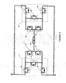
- FIG. 4 shows an embodiment of the single phase driving circuit disclosed in Fig. 3 on which a circuit is added according to an embodiment of the invention.
- the added circuit comprises a first element 71 and a second element 61 and it is intended to provide a remedial strategy in case of a failure of any one of the switches.
- the first element 71 and the second element 61 are similar to the circuit 34 disclosed in Fig. 2. It will be appreciated that redundancy is provided to the single phase driving circuit. Therefore increase reliability of the overall circuit is expected.
- circuit i.e., first element 71
- a prior art N-phase driving circuit for driving an N-phase component. More precisely, the N-phase driving circuit is used to drive a first phase 84, a second phase 94, a third phase 104 ... and an Nth-phase 116.
- the first phase 84 is driven by a first group of switches comprising switch 86 and switch 88.
- the first phase 84 is further driven by a second group of switches comprising switch 80 and switch 82.
- the second phase 94 is driven by a first group of switches comprising switch 90 and switch 92.
- the second phase 94 is further driven by a second group of switches comprising switch 96 and switch 98.
- the third phase 104 is driven by a first group of switches comprising switch 100 and switch 102.
- the third phase 104 is further driven by a second group of switches comprising switch 106 and switch 108.
- the Nth-phase 116 is driven by a first group of switches comprising switch 110 and switch 112.
- the Nth-phase 116 is further driven by a second group of switches comprising switch 114 and switch 118.
- each phase is driven similarly to the phase 63 as disclosed in Fig. 4. Furthermore, it will be appreciated that each first group of switches to a first power unit while each second group of switches is connected to a second power unit.
- the circuit comprises a first part 137 and a second part 127.
- the first part 137 comprises a first actuable switch 136, a second actuable switch 138 and a third actuable switch 140.
- the second part 127 comprises a first actuable switch 126, a second actuable switch 124 and a third actuable switch 128.
- the first actuable switch 136 is connected in parallel with the first switch 132 and the second switch 134, with the first switch 148 and the second switch 146, with the first switch 156 and the second switch 158, and with the first switch 166 and the second switch 168.
- the second actuable switch 138 is connected in series with a first end of the assembly comprising the first switch 132, in series with a first end of the assembly comprising the first switch 148, in series with a first end of the assembly comprising the first switch 156, in series with a first end of the assembly comprising the first switch 156.
- the third actuable switch 140 is connected in series with a second end of the assembly comprising the first switch 132 and the second switch 134, in series with a second end of the assembly comprising the first switch 148 and the second switch 134, in series with a second end of the assembly comprising the first switch 156 and the second switch 158, in series with a second end of the assembly comprising the first switch 166 and the second switch 168.
- first actuable switch 126 is connected in parallel with the first switch 120 and the second switch 122, in parallel with the first switch 142 and the second switch 144, in parallel with the first switch 152 and the second switch 154, in parallel with the first switch 162 and the second switch 154.
- the second actuable switch 124 is connected in series with a first end of the assembly comprising the first switch 120, in series with a first end of the assembly comprising the first switch 142, in series with a first end of the assembly comprising the first switch 152, in series with a first end of the assembly comprising the first switch 162.
- the third actuable switch 128 is connected in series with a second end of the assembly comprising the first switch 120 and the second switch 122, in series with a second end of the assembly comprising the first switch 142 and the second switch 144, in series with a second end of the assembly comprising the first switch 152 and the second switch 154, in series with a second end of the assembly comprising the first switch 162 and the second switch 164.
- a control unit not shown in Fig. 6, is used to drive switches 124, 126, 128, 136, 138 and 140.
Landscapes
- Engineering & Computer Science (AREA)
- Power Engineering (AREA)
- Power Conversion In General (AREA)
- Stand-By Power Supply Arrangements (AREA)
- Control Of Multiple Motors (AREA)
- Protection Of Static Devices (AREA)
Applications Claiming Priority (1)
| Application Number | Priority Date | Filing Date | Title |
|---|---|---|---|
| US11/175,185 US7352544B2 (en) | 2005-07-07 | 2005-07-07 | Method and apparatus for providing a remedial strategy for an electrical circuit |
Publications (2)
| Publication Number | Publication Date |
|---|---|
| EP1742339A2 true EP1742339A2 (de) | 2007-01-10 |
| EP1742339A3 EP1742339A3 (de) | 2010-03-03 |
Family
ID=36972704
Family Applications (1)
| Application Number | Title | Priority Date | Filing Date |
|---|---|---|---|
| EP06253581A Withdrawn EP1742339A3 (de) | 2005-07-07 | 2006-07-07 | Methode und Anordnung zur Fehlerbehebung in einer elektrischen Schaltung |
Country Status (4)
| Country | Link |
|---|---|
| US (1) | US7352544B2 (de) |
| EP (1) | EP1742339A3 (de) |
| CA (1) | CA2609040C (de) |
| WO (1) | WO2007006141A1 (de) |
Cited By (1)
| Publication number | Priority date | Publication date | Assignee | Title |
|---|---|---|---|---|
| EP3196913A1 (de) * | 2016-01-20 | 2017-07-26 | Schneider Electric Industries SAS | Relaisschaltung und verfahren zur selbsttestdurchführung einer relaisschaltung |
Families Citing this family (3)
| Publication number | Priority date | Publication date | Assignee | Title |
|---|---|---|---|---|
| US20210249981A1 (en) | 2018-09-05 | 2021-08-12 | Dpm Technologies Inc. | Systems and methods for intelligent control of rotating electric machines |
| US11967913B2 (en) | 2021-05-13 | 2024-04-23 | Exro Technologies Inc. | Method and apparatus to drive coils of a multiphase electric machine |
| CA3223051A1 (en) * | 2021-07-08 | 2023-01-12 | Eric HUSTEDT | Dynamically reconfigurable power converter utilizing windings of electrical machine |
Family Cites Families (22)
| Publication number | Priority date | Publication date | Assignee | Title |
|---|---|---|---|---|
| JPS4836303B1 (de) * | 1968-12-27 | 1973-11-02 | ||
| US3609507A (en) * | 1970-05-05 | 1971-09-28 | Garrett Corp | Polyphase inverter system having fault protection and output amplitude regulation through pulse width modulation |
| FR2447638A1 (fr) * | 1979-01-29 | 1980-08-22 | Cem Comp Electro Mec | Convertisseur statique de frequence |
| US4447867A (en) * | 1982-01-29 | 1984-05-08 | Varo, Inc. | Multiphase inverter drive circuit with synchronized switching delay feature |
| US4868826A (en) * | 1987-08-31 | 1989-09-19 | Triplex | Fault-tolerant output circuits |
| US4788415A (en) * | 1987-11-18 | 1988-11-29 | General Electric Company | Dual bimetal power control switching arrangement for electronically controlled appliances |
| US4939730A (en) * | 1988-10-11 | 1990-07-03 | Gilbarco Inc. | Auto isolation circuit for malfunctioning current loop |
| US5172310A (en) * | 1991-07-10 | 1992-12-15 | U.S. Windpower, Inc. | Low impedance bus for power electronics |
| US5191518A (en) * | 1991-08-15 | 1993-03-02 | Recker Bradley J | Plural inverter control arrangement |
| US5339235A (en) * | 1993-05-11 | 1994-08-16 | Alliedsignal Inc. | Fault compensating multi-step wave inverter |
| US5499186A (en) * | 1994-01-07 | 1996-03-12 | Hughes Aircraft Company | Three-phase power converter with fail soft characteristics |
| WO1995027931A1 (en) * | 1994-04-06 | 1995-10-19 | Utility Systems Technologies, Inc. | Load tap changer |
| AT405553B (de) * | 1994-09-06 | 1999-09-27 | Blum Gmbh Julius | Rahmenscharnier |
| WO1997001773A1 (en) * | 1995-06-29 | 1997-01-16 | The Nippon Signal Co., Ltd. | Mat sensor |
| US5685043A (en) * | 1995-07-24 | 1997-11-11 | Xerox Corporation | Removal of particulates from cylindrical members |
| JP3385893B2 (ja) * | 1997-02-21 | 2003-03-10 | トヨタ自動車株式会社 | 内燃機関用空燃比センサのヒータ制御装置 |
| GB9713136D0 (en) * | 1997-06-20 | 1997-08-27 | Switched Reluctance Drives Ltd | Switching circuit for a reluctance machine |
| AU1592001A (en) | 1999-11-11 | 2001-06-06 | Raytheon Company | Fail-safe, fault-tolerant switching system for a critical device |
| US6566764B2 (en) * | 2000-05-23 | 2003-05-20 | Vestas Wind Systems A/S, R&D | Variable speed wind turbine having a matrix converter |
| KR100438777B1 (ko) * | 2001-11-06 | 2004-07-05 | 삼성전자주식회사 | 공동이 형성된 가요성 인쇄회로를 구비하는 하드디스크드라이브 |
| US7129599B2 (en) * | 2002-10-15 | 2006-10-31 | Soft Switching Technologies Corporation | Dual feed power supply systems with enhanced power quality |
| US7128120B2 (en) * | 2004-02-10 | 2006-10-31 | David Orbeck | Assembly of sashes for sliding glass doors |
-
2005
- 2005-07-07 US US11/175,185 patent/US7352544B2/en active Active
-
2006
- 2006-07-07 WO PCT/CA2006/001122 patent/WO2007006141A1/en not_active Ceased
- 2006-07-07 EP EP06253581A patent/EP1742339A3/de not_active Withdrawn
- 2006-07-07 CA CA2609040A patent/CA2609040C/en not_active Expired - Fee Related
Cited By (2)
| Publication number | Priority date | Publication date | Assignee | Title |
|---|---|---|---|---|
| EP3196913A1 (de) * | 2016-01-20 | 2017-07-26 | Schneider Electric Industries SAS | Relaisschaltung und verfahren zur selbsttestdurchführung einer relaisschaltung |
| US10395869B2 (en) | 2016-01-20 | 2019-08-27 | Schneider Electric Industries Sas | Relay circuit and method for performing self-test of relay circuit |
Also Published As
| Publication number | Publication date |
|---|---|
| US7352544B2 (en) | 2008-04-01 |
| WO2007006141A1 (en) | 2007-01-18 |
| EP1742339A3 (de) | 2010-03-03 |
| CA2609040C (en) | 2015-05-26 |
| CA2609040A1 (en) | 2007-01-18 |
| US20070008669A1 (en) | 2007-01-11 |
Similar Documents
| Publication | Publication Date | Title |
|---|---|---|
| KR101756578B1 (ko) | 전원 장치 | |
| CN103797714B (zh) | 栅极控制电路、功率模块和相关联的方法 | |
| CN119487740A (zh) | 直流母线的主动放电 | |
| US5499186A (en) | Three-phase power converter with fail soft characteristics | |
| US8937451B2 (en) | Motor control apparatus which discharges stored charge of DC voltage smoothing capacitor when operation becomes halted | |
| CN102939714A (zh) | 电压逆变器和控制这种逆变器的方法 | |
| CN102237849A (zh) | 电动机驱动装置 | |
| JP2003289633A (ja) | 無停電電源装置の並列運転方法 | |
| JP6469894B2 (ja) | 電力変換装置 | |
| JP6921319B2 (ja) | 電力変換装置 | |
| CN103548266B (zh) | 用于运行功率输出级的方法和装置 | |
| JP2010252536A (ja) | インバータ装置及びその故障診断方法 | |
| US10978975B2 (en) | Fault-tolerant electrical drive | |
| US20040222766A1 (en) | Inverter for an electric machine | |
| US7352544B2 (en) | Method and apparatus for providing a remedial strategy for an electrical circuit | |
| CN103354975B (zh) | 具有电励磁机的系统 | |
| CN111034046A (zh) | 连接单元及电源系统 | |
| JP2019009894A (ja) | 検出装置 | |
| JP4388573B2 (ja) | 車両用回転電機装置 | |
| JP2014165956A (ja) | 回転電機駆動装置 | |
| FI116175B (fi) | Menetelmä ja järjestely taajuusmuuttajan suojaamiseksi | |
| JP7206392B2 (ja) | 電圧変換器を制御するためのシステム | |
| CN112744085A (zh) | 电动汽车及其集成控制器、集成控制系统 | |
| CN108400394B (zh) | 电池管理系统的电子开关装置以及电池 | |
| JP2020096439A (ja) | 電源制御装置 |
Legal Events
| Date | Code | Title | Description |
|---|---|---|---|
| PUAI | Public reference made under article 153(3) epc to a published international application that has entered the european phase |
Free format text: ORIGINAL CODE: 0009012 |
|
| AK | Designated contracting states |
Kind code of ref document: A2 Designated state(s): AT BE BG CH CY CZ DE DK EE ES FI FR GB GR HU IE IS IT LI LT LU LV MC NL PL PT RO SE SI SK TR |
|
| AX | Request for extension of the european patent |
Extension state: AL BA HR MK YU |
|
| PUAL | Search report despatched |
Free format text: ORIGINAL CODE: 0009013 |
|
| AK | Designated contracting states |
Kind code of ref document: A3 Designated state(s): AT BE BG CH CY CZ DE DK EE ES FI FR GB GR HU IE IS IT LI LT LU LV MC NL PL PT RO SE SI SK TR |
|
| AX | Request for extension of the european patent |
Extension state: AL BA HR MK RS |
|
| 17P | Request for examination filed |
Effective date: 20100505 |
|
| 17Q | First examination report despatched |
Effective date: 20100528 |
|
| AKX | Designation fees paid |
Designated state(s): DE FR GB |
|
| STAA | Information on the status of an ep patent application or granted ep patent |
Free format text: STATUS: THE APPLICATION IS DEEMED TO BE WITHDRAWN |
|
| 18D | Application deemed to be withdrawn |
Effective date: 20101208 |