EP1741971A2 - Methode et appareil pour le traitement de GNL - Google Patents
Methode et appareil pour le traitement de GNL Download PDFInfo
- Publication number
- EP1741971A2 EP1741971A2 EP06114693A EP06114693A EP1741971A2 EP 1741971 A2 EP1741971 A2 EP 1741971A2 EP 06114693 A EP06114693 A EP 06114693A EP 06114693 A EP06114693 A EP 06114693A EP 1741971 A2 EP1741971 A2 EP 1741971A2
- Authority
- EP
- European Patent Office
- Prior art keywords
- stream
- vessel
- lng
- supplied
- inert fluid
- Prior art date
- Legal status (The legal status is an assumption and is not a legal conclusion. Google has not performed a legal analysis and makes no representation as to the accuracy of the status listed.)
- Withdrawn
Links
Images
Classifications
-
- F—MECHANICAL ENGINEERING; LIGHTING; HEATING; WEAPONS; BLASTING
- F17—STORING OR DISTRIBUTING GASES OR LIQUIDS
- F17C—VESSELS FOR CONTAINING OR STORING COMPRESSED, LIQUEFIED OR SOLIDIFIED GASES; FIXED-CAPACITY GAS-HOLDERS; FILLING VESSELS WITH, OR DISCHARGING FROM VESSELS, COMPRESSED, LIQUEFIED, OR SOLIDIFIED GASES
- F17C7/00—Methods or apparatus for discharging liquefied, solidified, or compressed gases from pressure vessels, not covered by another subclass
- F17C7/02—Discharging liquefied gases
-
- F—MECHANICAL ENGINEERING; LIGHTING; HEATING; WEAPONS; BLASTING
- F17—STORING OR DISTRIBUTING GASES OR LIQUIDS
- F17C—VESSELS FOR CONTAINING OR STORING COMPRESSED, LIQUEFIED OR SOLIDIFIED GASES; FIXED-CAPACITY GAS-HOLDERS; FILLING VESSELS WITH, OR DISCHARGING FROM VESSELS, COMPRESSED, LIQUEFIED, OR SOLIDIFIED GASES
- F17C2221/00—Handled fluid, in particular type of fluid
- F17C2221/03—Mixtures
- F17C2221/032—Hydrocarbons
- F17C2221/033—Methane, e.g. natural gas, CNG, LNG, GNL, GNC, PLNG
-
- F—MECHANICAL ENGINEERING; LIGHTING; HEATING; WEAPONS; BLASTING
- F17—STORING OR DISTRIBUTING GASES OR LIQUIDS
- F17C—VESSELS FOR CONTAINING OR STORING COMPRESSED, LIQUEFIED OR SOLIDIFIED GASES; FIXED-CAPACITY GAS-HOLDERS; FILLING VESSELS WITH, OR DISCHARGING FROM VESSELS, COMPRESSED, LIQUEFIED, OR SOLIDIFIED GASES
- F17C2223/00—Handled fluid before transfer, i.e. state of fluid when stored in the vessel or before transfer from the vessel
- F17C2223/01—Handled fluid before transfer, i.e. state of fluid when stored in the vessel or before transfer from the vessel characterised by the phase
- F17C2223/0146—Two-phase
- F17C2223/0153—Liquefied gas, e.g. LPG, GPL
- F17C2223/0161—Liquefied gas, e.g. LPG, GPL cryogenic, e.g. LNG, GNL, PLNG
-
- F—MECHANICAL ENGINEERING; LIGHTING; HEATING; WEAPONS; BLASTING
- F17—STORING OR DISTRIBUTING GASES OR LIQUIDS
- F17C—VESSELS FOR CONTAINING OR STORING COMPRESSED, LIQUEFIED OR SOLIDIFIED GASES; FIXED-CAPACITY GAS-HOLDERS; FILLING VESSELS WITH, OR DISCHARGING FROM VESSELS, COMPRESSED, LIQUEFIED, OR SOLIDIFIED GASES
- F17C2223/00—Handled fluid before transfer, i.e. state of fluid when stored in the vessel or before transfer from the vessel
- F17C2223/01—Handled fluid before transfer, i.e. state of fluid when stored in the vessel or before transfer from the vessel characterised by the phase
- F17C2223/0146—Two-phase
- F17C2223/0153—Liquefied gas, e.g. LPG, GPL
- F17C2223/0169—Liquefied gas, e.g. LPG, GPL subcooled
-
- F—MECHANICAL ENGINEERING; LIGHTING; HEATING; WEAPONS; BLASTING
- F17—STORING OR DISTRIBUTING GASES OR LIQUIDS
- F17C—VESSELS FOR CONTAINING OR STORING COMPRESSED, LIQUEFIED OR SOLIDIFIED GASES; FIXED-CAPACITY GAS-HOLDERS; FILLING VESSELS WITH, OR DISCHARGING FROM VESSELS, COMPRESSED, LIQUEFIED, OR SOLIDIFIED GASES
- F17C2223/00—Handled fluid before transfer, i.e. state of fluid when stored in the vessel or before transfer from the vessel
- F17C2223/03—Handled fluid before transfer, i.e. state of fluid when stored in the vessel or before transfer from the vessel characterised by the pressure level
- F17C2223/035—High pressure (>10 bar)
-
- F—MECHANICAL ENGINEERING; LIGHTING; HEATING; WEAPONS; BLASTING
- F17—STORING OR DISTRIBUTING GASES OR LIQUIDS
- F17C—VESSELS FOR CONTAINING OR STORING COMPRESSED, LIQUEFIED OR SOLIDIFIED GASES; FIXED-CAPACITY GAS-HOLDERS; FILLING VESSELS WITH, OR DISCHARGING FROM VESSELS, COMPRESSED, LIQUEFIED, OR SOLIDIFIED GASES
- F17C2225/00—Handled fluid after transfer, i.e. state of fluid after transfer from the vessel
- F17C2225/01—Handled fluid after transfer, i.e. state of fluid after transfer from the vessel characterised by the phase
- F17C2225/0107—Single phase
- F17C2225/0123—Single phase gaseous, e.g. CNG, GNC
-
- F—MECHANICAL ENGINEERING; LIGHTING; HEATING; WEAPONS; BLASTING
- F17—STORING OR DISTRIBUTING GASES OR LIQUIDS
- F17C—VESSELS FOR CONTAINING OR STORING COMPRESSED, LIQUEFIED OR SOLIDIFIED GASES; FIXED-CAPACITY GAS-HOLDERS; FILLING VESSELS WITH, OR DISCHARGING FROM VESSELS, COMPRESSED, LIQUEFIED, OR SOLIDIFIED GASES
- F17C2225/00—Handled fluid after transfer, i.e. state of fluid after transfer from the vessel
- F17C2225/03—Handled fluid after transfer, i.e. state of fluid after transfer from the vessel characterised by the pressure level
- F17C2225/035—High pressure, i.e. between 10 and 80 bars
-
- F—MECHANICAL ENGINEERING; LIGHTING; HEATING; WEAPONS; BLASTING
- F17—STORING OR DISTRIBUTING GASES OR LIQUIDS
- F17C—VESSELS FOR CONTAINING OR STORING COMPRESSED, LIQUEFIED OR SOLIDIFIED GASES; FIXED-CAPACITY GAS-HOLDERS; FILLING VESSELS WITH, OR DISCHARGING FROM VESSELS, COMPRESSED, LIQUEFIED, OR SOLIDIFIED GASES
- F17C2225/00—Handled fluid after transfer, i.e. state of fluid after transfer from the vessel
- F17C2225/03—Handled fluid after transfer, i.e. state of fluid after transfer from the vessel characterised by the pressure level
- F17C2225/036—Very high pressure, i.e. above 80 bars
-
- F—MECHANICAL ENGINEERING; LIGHTING; HEATING; WEAPONS; BLASTING
- F17—STORING OR DISTRIBUTING GASES OR LIQUIDS
- F17C—VESSELS FOR CONTAINING OR STORING COMPRESSED, LIQUEFIED OR SOLIDIFIED GASES; FIXED-CAPACITY GAS-HOLDERS; FILLING VESSELS WITH, OR DISCHARGING FROM VESSELS, COMPRESSED, LIQUEFIED, OR SOLIDIFIED GASES
- F17C2227/00—Transfer of fluids, i.e. method or means for transferring the fluid; Heat exchange with the fluid
- F17C2227/03—Heat exchange with the fluid
- F17C2227/0302—Heat exchange with the fluid by heating
-
- F—MECHANICAL ENGINEERING; LIGHTING; HEATING; WEAPONS; BLASTING
- F17—STORING OR DISTRIBUTING GASES OR LIQUIDS
- F17C—VESSELS FOR CONTAINING OR STORING COMPRESSED, LIQUEFIED OR SOLIDIFIED GASES; FIXED-CAPACITY GAS-HOLDERS; FILLING VESSELS WITH, OR DISCHARGING FROM VESSELS, COMPRESSED, LIQUEFIED, OR SOLIDIFIED GASES
- F17C2227/00—Transfer of fluids, i.e. method or means for transferring the fluid; Heat exchange with the fluid
- F17C2227/03—Heat exchange with the fluid
- F17C2227/0367—Localisation of heat exchange
- F17C2227/0388—Localisation of heat exchange separate
- F17C2227/0393—Localisation of heat exchange separate using a vaporiser
-
- F—MECHANICAL ENGINEERING; LIGHTING; HEATING; WEAPONS; BLASTING
- F17—STORING OR DISTRIBUTING GASES OR LIQUIDS
- F17C—VESSELS FOR CONTAINING OR STORING COMPRESSED, LIQUEFIED OR SOLIDIFIED GASES; FIXED-CAPACITY GAS-HOLDERS; FILLING VESSELS WITH, OR DISCHARGING FROM VESSELS, COMPRESSED, LIQUEFIED, OR SOLIDIFIED GASES
- F17C2260/00—Purposes of gas storage and gas handling
- F17C2260/05—Improving chemical properties
- F17C2260/056—Improving fluid characteristics
-
- F—MECHANICAL ENGINEERING; LIGHTING; HEATING; WEAPONS; BLASTING
- F17—STORING OR DISTRIBUTING GASES OR LIQUIDS
- F17C—VESSELS FOR CONTAINING OR STORING COMPRESSED, LIQUEFIED OR SOLIDIFIED GASES; FIXED-CAPACITY GAS-HOLDERS; FILLING VESSELS WITH, OR DISCHARGING FROM VESSELS, COMPRESSED, LIQUEFIED, OR SOLIDIFIED GASES
- F17C2265/00—Effects achieved by gas storage or gas handling
- F17C2265/03—Treating the boil-off
- F17C2265/032—Treating the boil-off by recovery
- F17C2265/033—Treating the boil-off by recovery with cooling
- F17C2265/034—Treating the boil-off by recovery with cooling with condensing the gas phase
-
- F—MECHANICAL ENGINEERING; LIGHTING; HEATING; WEAPONS; BLASTING
- F17—STORING OR DISTRIBUTING GASES OR LIQUIDS
- F17C—VESSELS FOR CONTAINING OR STORING COMPRESSED, LIQUEFIED OR SOLIDIFIED GASES; FIXED-CAPACITY GAS-HOLDERS; FILLING VESSELS WITH, OR DISCHARGING FROM VESSELS, COMPRESSED, LIQUEFIED, OR SOLIDIFIED GASES
- F17C2265/00—Effects achieved by gas storage or gas handling
- F17C2265/03—Treating the boil-off
- F17C2265/032—Treating the boil-off by recovery
- F17C2265/037—Treating the boil-off by recovery with pressurising
-
- F—MECHANICAL ENGINEERING; LIGHTING; HEATING; WEAPONS; BLASTING
- F17—STORING OR DISTRIBUTING GASES OR LIQUIDS
- F17C—VESSELS FOR CONTAINING OR STORING COMPRESSED, LIQUEFIED OR SOLIDIFIED GASES; FIXED-CAPACITY GAS-HOLDERS; FILLING VESSELS WITH, OR DISCHARGING FROM VESSELS, COMPRESSED, LIQUEFIED, OR SOLIDIFIED GASES
- F17C2265/00—Effects achieved by gas storage or gas handling
- F17C2265/05—Regasification
Definitions
- the present invention relates to a method of treating a liquefied natural gas (LNG) stream.
- LNG liquefied natural gas
- natural gas can be stored and transported over long distances more readily as a liquid than in gaseous form, because it occupies a smaller volume and does not need to be stored at high pressures.
- the nitrogen is usually injected into the regasified LNG. To this end the nitrogen needs to be compressed to similar or higher pressure than the regasified LNG.
- a problem of the known methods of treating an LNG stream as described above is that it is highly energy consuming.
- LNG liquefied natural gas
- a further advantage of the present invention is that the occurrence of cavitation in downstream pumps is prevented or at least minimized.
- the liquefied natural gas stream supplied in step (a) may be any LNG stream, and will usually be obtained from an LNG storage tank.
- the LNG comprises compounds selected from the group consisting of methane, ethane, propane, butanes and pentanes, or a combination thereof. Also other hydrocarbons may be present.
- the LNG stream is low in aromatic hydrocarbons and non-hydrocarbons such as H 2 O, N 2 , CO 2 , H 2 S and other sulphur compounds, and the like, as these compounds have usually been removed at least partially before liquefying the natural gas stream, which is then stored or transported in liquid form.
- the inert fluid may be any suitable vaporous or liquid fluid for selectively adjusting the energy content of the LNG.
- air or substantially pure N 2 may be used.
- the energy content can be adjusted using the inert fluid, this is not further discussed here.
- the inert fluid may be supplied to the vessel separately from the LNG stream (preferably at the top of the vessel), but both streams may also first be combined and subsequently be supplied as a single stream to the vessel (again, preferably at the top of the vessel).
- the vessel in which the inert fluid and LNG are contacted may be any suitable vessel, as long as it contains a contacting zone, i.e. a section in which the inert fluid and LNG are contacted.
- the contacting zone comprises a packing to further enhance the contact.
- step (a) the stream comprising LNG is supplied to the vessel at a pressure of from 4 to 13 bar, preferably from 6 to 11 bar, more preferably from 7 to 10 bar.
- the stream supplied in step (b) comprises at least 75 vol% N 2 , preferably at least 80 vol% N 2 , more preferably at least 90 vol% N 2 .
- the amount of N 2 supplied in step (b) is selected such that the LNG stream removed in step (d) comprises at most 5 vol% N 2 .
- the method further comprises the steps of:
- a boil off vapour stream is supplied to the vessel, the boil off vapour stream originating from a source of LNG.
- the boil off vapour stream is supplied to the vessel at a pressure of from 4 to 13 bar, preferably from 6 to 11 bar, more preferably from 7 to 10 bar.
- the inert fluid may be supplied to the vessel separately from the boil off vapour stream, but both streams may also first be combined and subsequently be supplied as a single stream to the vessel.
- the inert fluid is combined with the boil off vapour stream having a pressure of 4 to 13 bar before being supplied to the vessel.
- the inert fluid stream preferably also has a pressure of from 4 to 13 bar.
- An important advantage of adding the inert fluid to the boil off vapour stream is that hereby the formation of bubbles ('cavitation') in the LNG stream removed in step (d) is substantially prevented. These bubbles might occur if the inert fluid would e.g. be added to the second stream being fed below the contacting zone, as is suggested e.g. in earlier filed but non-prepublished application WO 2005/061951 A1 .
- the presence of bubbles in the LNG stream removed in step (d) may be harmful for downstream pumps.
- the LNG stream supplied in step (a) is a subcooled LNG stream.
- a part of the cold in the subcooled LNG stream is used to recondense the boil off vapour stream and the inert fluid.
- the present invention relates to an apparatus for treating a liquefied natural gas (LNG) stream, the apparatus at least comprising a vessel, the vessel comprising:
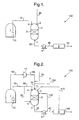
- Figure 1 schematically shows a process scheme (and apparatus generally indicated with reference number 100) not in accordance with the present invention (as it does not show all the features of the main claims), but incorporated for illustration purposes only.
- a stream 10 containing liquefied natural gas (LNG) is pumped (using e.g. an in-tank pump 13) from an LNG source such as a storage tank 1 to the first inlet 4 of a vessel 2 having a contacting zone 3 such as a packing.
- LNG liquefied natural gas
- the stream 10 is a subcooled LNG stream and has a pressure of between 4 to 13 bar, preferably about 8 bar, while the pressure of the LNG in the storage tank 1 is about atmospheric.
- a stream 20 being substantially comprised of N 2 is supplied to the vessel 2 at an inlet 6 of the vessel 2.
- a stream 30 is removed at outlet 7 from the vessel 2.
- the stream 30 preferably contains at most 5 vol% N 2 .
- the stream 30 is further processed by pressurizing in a high-pressure pump 8 thereby obtaining a stream 40 having a pressure in the range of about 8 to 110 bar. Then, the stream 40 is vaporised in a vaporiser 9 thereby obtaining a gaseous natural gas stream 50 having a selected energy content, which may be sent to the grid (not shown).
- the amount of N 2 supplied to the vessel 2 will depend on the desired energy content for the natural gas to be obtained in stream 50.
- FIG 2 shows an exemplary process scheme of an embodiment of the method according to the present invention, which process scheme can be used in an LNG import terminal. The elements already discussed in Figure 1 will not be discussed here again.
- stream 10 is supplied as two separate streams to the vessel 2, i.e. first stream 80 and second stream 90; the first stream 80 is fed above the contacting zone 3 at first inlet 4 and the second stream 90 is fed below the contacting zone 3 at second inlet 5.
- stream 10 may be supplied to the vessel 2 as more than two separate streams.
- a boil off vapour stream 60 coming from the LNG storage tank 1 is fed to the vessel 2 at third inlet 11.
- the third inlet 11 is preferably at the top of the vessel 2, above the contacting zone 3.
- stream 60 Before feeding the stream 60 to the vessel 2, it is pressurized by compressing the stream 60 (usually being at atmospheric pressure) in compressor 12 thereby obtaining compressed boil off vapour stream 65.
- stream 20 and stream 65 By combining stream 20 and stream 65, combined stream 70 is obtained.
- the stream 70 usually has a pressure in the range of 4 to 13 bar, preferably about 8 bar.
- streams 65 and 20 may be added as separate streams (and as a result at separate inlets) to the vessel 2, preferably at the top of the vessel 2. However, it is preferred to combine streams 65 and 20 before supplying it as combined stream 70 to the vessel 2 at third inlet 11 (being preferably at the top of the vessel 2).
- stream 120 is fed as a kickback stream from the high-pressure pump 8 to the vessel 2.
- Table I gives an overview of the composition and conditions of a stream at various parts in an example process of Fig. 2.
- the energy content (i.e. heating value) of stream 10 has been selectively adjusted (i.e. decreased) from 1170 to a value of 1116 Btu/scf in stream 30.
- the temperature and pressure of the streams 80 and 90 differ slightly, as the pipe for stream 90 is longer. As a result stream 90 experiences more cold leak and more pressure drop than stream 80.
Landscapes
- Engineering & Computer Science (AREA)
- Mechanical Engineering (AREA)
- General Engineering & Computer Science (AREA)
- Filling Or Discharging Of Gas Storage Vessels (AREA)
Priority Applications (1)
| Application Number | Priority Date | Filing Date | Title |
|---|---|---|---|
| EP06114693A EP1741971A3 (fr) | 2005-06-01 | 2006-05-30 | Methode et appareil pour le traitement de GNL |
Applications Claiming Priority (3)
| Application Number | Priority Date | Filing Date | Title |
|---|---|---|---|
| EP2005006636 | 2005-06-01 | ||
| EP2005053363 | 2005-07-13 | ||
| EP06114693A EP1741971A3 (fr) | 2005-06-01 | 2006-05-30 | Methode et appareil pour le traitement de GNL |
Publications (2)
| Publication Number | Publication Date |
|---|---|
| EP1741971A2 true EP1741971A2 (fr) | 2007-01-10 |
| EP1741971A3 EP1741971A3 (fr) | 2011-07-20 |
Family
ID=37429309
Family Applications (1)
| Application Number | Title | Priority Date | Filing Date |
|---|---|---|---|
| EP06114693A Withdrawn EP1741971A3 (fr) | 2005-06-01 | 2006-05-30 | Methode et appareil pour le traitement de GNL |
Country Status (1)
| Country | Link |
|---|---|
| EP (1) | EP1741971A3 (fr) |
Cited By (1)
| Publication number | Priority date | Publication date | Assignee | Title |
|---|---|---|---|---|
| KR102215060B1 (ko) * | 2019-11-15 | 2021-02-10 | (주)발맥스기술 | Lng 증발가스의 응축장치 및 제어방법 |
Citations (3)
| Publication number | Priority date | Publication date | Assignee | Title |
|---|---|---|---|---|
| US3658499A (en) | 1970-10-28 | 1972-04-25 | Chicago Bridge & Iron Co | Method of diluting liquefied gases |
| GB1280342A (en) | 1968-07-03 | 1972-07-05 | Air Liquide | An installation for, and a method of obtaining, a fluid rich in methane at a high pressure |
| WO2005061951A1 (fr) | 2003-12-15 | 2005-07-07 | Bp Corporatoin North America Inc. | Systemes et procedes de vaporisation de gaz naturel liquefie |
Family Cites Families (1)
| Publication number | Priority date | Publication date | Assignee | Title |
|---|---|---|---|---|
| FR1603033A (en) * | 1968-07-03 | 1971-03-15 | Production of high methan gas |
-
2006
- 2006-05-30 EP EP06114693A patent/EP1741971A3/fr not_active Withdrawn
Patent Citations (3)
| Publication number | Priority date | Publication date | Assignee | Title |
|---|---|---|---|---|
| GB1280342A (en) | 1968-07-03 | 1972-07-05 | Air Liquide | An installation for, and a method of obtaining, a fluid rich in methane at a high pressure |
| US3658499A (en) | 1970-10-28 | 1972-04-25 | Chicago Bridge & Iron Co | Method of diluting liquefied gases |
| WO2005061951A1 (fr) | 2003-12-15 | 2005-07-07 | Bp Corporatoin North America Inc. | Systemes et procedes de vaporisation de gaz naturel liquefie |
Cited By (1)
| Publication number | Priority date | Publication date | Assignee | Title |
|---|---|---|---|---|
| KR102215060B1 (ko) * | 2019-11-15 | 2021-02-10 | (주)발맥스기술 | Lng 증발가스의 응축장치 및 제어방법 |
Also Published As
| Publication number | Publication date |
|---|---|
| EP1741971A3 (fr) | 2011-07-20 |
Similar Documents
| Publication | Publication Date | Title |
|---|---|---|
| US20070001322A1 (en) | Method and apparatus for treating lng | |
| US7299655B2 (en) | Systems and methods for vaporization of liquefied natural gas | |
| JP5219306B2 (ja) | 沖合でのlngの再ガス化および発熱量の調節のための構成および方法 | |
| JP4759571B2 (ja) | Lng再ガス化とbtu制御のための構成および方法 | |
| US8505312B2 (en) | Liquid natural gas fractionation and regasification plant | |
| US20080264492A1 (en) | Methods for pressurizing boil off gas | |
| US20130298572A1 (en) | Configurations and methods of vapor recovery and lng sendout systems for lng import terminals | |
| EP1996855B1 (fr) | Méthode et système de regazéification de gnl | |
| US20050061029A1 (en) | Process and apparatus for LNG enriching in methane | |
| US20200393196A1 (en) | Device and method for processing boil-off gas in liquefied gas regasification system | |
| EP3262359B1 (fr) | Appareil d'alimentation en gaz combustible liquéfié | |
| EP1741971A2 (fr) | Methode et appareil pour le traitement de GNL | |
| KR101984978B1 (ko) | 액화가스 추진선박 | |
| KR20040023658A (ko) | 가압 액화 천연 가스를 액화 천연 가스 저장 설비에저장하는 시스템 및 방법 | |
| US8499581B2 (en) | Gas conditioning method and apparatus for the recovery of LPG/NGL(C2+) from LNG | |
| JP7204888B2 (ja) | 天然ガス液化プラントにおけるボイルオフガス再循環サブシステム | |
| MXPA06006150A (en) | Method and apparatus for treating lng | |
| EP3837482A1 (fr) | Conservation de fluide frigorigène mixte dans des installations de liquéfaction de gaz naturel | |
| KR20200073790A (ko) | Lpg 증발가스의 재액화 시스템 |
Legal Events
| Date | Code | Title | Description |
|---|---|---|---|
| PUAI | Public reference made under article 153(3) epc to a published international application that has entered the european phase |
Free format text: ORIGINAL CODE: 0009012 |
|
| AK | Designated contracting states |
Kind code of ref document: A2 Designated state(s): AT BE BG CH CY CZ DE DK EE ES FI FR GB GR HU IE IS IT LI LT LU LV MC NL PL PT RO SE SI SK TR |
|
| AX | Request for extension of the european patent |
Extension state: AL BA HR MK YU |
|
| REG | Reference to a national code |
Ref country code: DE Ref legal event code: R079 Free format text: PREVIOUS MAIN CLASS: F17C0007020000 Ipc: F17C0009020000 |
|
| PUAL | Search report despatched |
Free format text: ORIGINAL CODE: 0009013 |
|
| AK | Designated contracting states |
Kind code of ref document: A3 Designated state(s): AT BE BG CH CY CZ DE DK EE ES FI FR GB GR HU IE IS IT LI LT LU LV MC NL PL PT RO SE SI SK TR |
|
| AX | Request for extension of the european patent |
Extension state: AL BA HR MK YU |
|
| RIC1 | Information provided on ipc code assigned before grant |
Ipc: F17C 9/02 20060101AFI20110614BHEP |
|
| AKX | Designation fees paid |
Designated state(s): AT BE BG CH CY CZ DE DK EE ES FI FR GB GR HU IE IS IT LI LT LU LV MC NL PL PT RO SE SI SK TR |
|
| STAA | Information on the status of an ep patent application or granted ep patent |
Free format text: STATUS: THE APPLICATION IS DEEMED TO BE WITHDRAWN |
|
| 18D | Application deemed to be withdrawn |
Effective date: 20111201 |