EP1741384A2 - System zur Leistungseinstellung für eine medizinische Vorrichtung - Google Patents
System zur Leistungseinstellung für eine medizinische Vorrichtung Download PDFInfo
- Publication number
- EP1741384A2 EP1741384A2 EP06253582A EP06253582A EP1741384A2 EP 1741384 A2 EP1741384 A2 EP 1741384A2 EP 06253582 A EP06253582 A EP 06253582A EP 06253582 A EP06253582 A EP 06253582A EP 1741384 A2 EP1741384 A2 EP 1741384A2
- Authority
- EP
- European Patent Office
- Prior art keywords
- light emitting
- emitting device
- patient medical
- emitting devices
- power
- Prior art date
- Legal status (The legal status is an assumption and is not a legal conclusion. Google has not performed a legal analysis and makes no representation as to the accuracy of the status listed.)
- Granted
Links
Images


Classifications
-
- A—HUMAN NECESSITIES
- A61—MEDICAL OR VETERINARY SCIENCE; HYGIENE
- A61B—DIAGNOSIS; SURGERY; IDENTIFICATION
- A61B5/00—Measuring for diagnostic purposes; Identification of persons
- A61B5/145—Measuring characteristics of blood in vivo, e.g. gas concentration or pH-value ; Measuring characteristics of body fluids or tissues, e.g. interstitial fluid or cerebral tissue
- A61B5/1455—Measuring characteristics of blood in vivo, e.g. gas concentration or pH-value ; Measuring characteristics of body fluids or tissues, e.g. interstitial fluid or cerebral tissue using optical sensors, e.g. spectral photometrical oximeters
- A61B5/14551—Measuring characteristics of blood in vivo, e.g. gas concentration or pH-value ; Measuring characteristics of body fluids or tissues, e.g. interstitial fluid or cerebral tissue using optical sensors, e.g. spectral photometrical oximeters for measuring blood gases
-
- A—HUMAN NECESSITIES
- A61—MEDICAL OR VETERINARY SCIENCE; HYGIENE
- A61B—DIAGNOSIS; SURGERY; IDENTIFICATION
- A61B2560/00—Constructional details of operational features of apparatus; Accessories for medical measuring apparatus
- A61B2560/02—Operational features
- A61B2560/0204—Operational features of power management
- A61B2560/0209—Operational features of power management adapted for power saving
-
- A—HUMAN NECESSITIES
- A61—MEDICAL OR VETERINARY SCIENCE; HYGIENE
- A61B—DIAGNOSIS; SURGERY; IDENTIFICATION
- A61B5/00—Measuring for diagnostic purposes; Identification of persons
- A61B5/72—Signal processing specially adapted for physiological signals or for diagnostic purposes
- A61B5/7235—Details of waveform analysis
- A61B5/7253—Details of waveform analysis characterised by using transforms
- A61B5/7257—Details of waveform analysis characterised by using transforms using Fourier transforms
Definitions
- the present invention relates to power conservation in portable medical devices, and in particular to power conservation in portable medical devices which use light emitting devices.
- a system for adjusting power employed by a medical device incorporating light emitting devices and being used for measuring patient medical parameters includes a plurality of light emitting devices.
- a power unit is coupled to the light emitting devices and powers the light emitting devices responsive to respective control signals which determine power to be applied to the light emitting devices.
- a control unit provides the control signals and is coupled to the power unit. The control signals intermittently turn off at least one of the plurality of light emitting devices in a power save mode in response to a determination that a patient medical parameter value measured by the medical device, using an active light emitting device of the plurality of light emitting devices, is at a safe level.
- a system for adjusting power employed by a medical device incorporating light emitting devices and being used for measuring patient medical parameters comprising:
- said control unit determines a patient medical parameter value comprising a blood oxygen saturation representative value is at said safe level by being above a predetermined threshold.
- said control unit determines a patient medical parameter value comprising a pulse rate is at said safe level by being within a predetermined range.
- the patient medical parameter may comprise at least one of:
- a system for adjusting power employed by a medical device incorporating light emitting devices and being used for measuring patient medical parameters comprising:
- said control unit uses said stored parameter value obtained using said first light emitting device together with a parameter value obtained using an active second light emitting device to determine said patient medical parameter value measured by said medical device is at a safe level.
- the system may further comprise:
- the control unit may provide control signals for progressively turning off processing functions of said plurality of processing functions in said power save mode in response to sensitivity determinations.
- a subset of the plurality of processing functions operates in the frequency domain; the system further comprises a fast Fourier transform (FFT) processing function, for transforming a set of time domain input samples, representing respective signals from said plurality of light emitting devices, into a corresponding set of frequency domain samples; and said control unit provides control signals for reducing the processing required to produce said frequency domain samples in said power save mode.
- FFT fast Fourier transform
- the number of samples In the set of time domain samples may be reduced in said power save mode.
- the rate at which successive sets of time domain samples are transformed into corresponding sets of frequency domain output samples may be reduced in said power save mode.
- the control unit may provide a control signal for turning off said at least one of said plurality of light emitting devices in a power save mode for a user configurable predetermined time duration and monitor a patient medical parameter that is measured without using said at least one of said plurality of light emitting devices;
- said control unit may terminate said power save mode and turn on said at least one of said plurality of light emitting devices.
- a system for adjusting power employed by a medical device incorporating light emitting devices and being used for measuring patient medical parameters comprising:
- the control unit may provide a control signal turning off operation of medical device functions unused in deriving said patient medical parameter that is measured without using said light emitting device.
- the system may further comprise:
- the monitored patient medical parameter value may comprise at least one of:
- the predetermined time duration may be user configurable.
- the predetermined time duration may be adjustable by said system.
- a system for adjusting power employed by a medical device incorporating light emitting devices and being used for measuring patient medical parameters comprising:
- the patient medical parameter derived using said light emitting device may comprise at least one of, (a) a blood oxygen saturation representative parameter and (b) a pulse rate.
- a system for adjusting power employed by a medical device incorporating light emitting devices and being used for measuring patient medical parameters comprising:
- said predetermined function disablement procedure turns off said at least one processing function in response to a sensitivity determination, said sensitivity determination being used to turn off a function having least effect in said determination of said patient medical parameter value measured by said medical device.
- the control unit may provide control signals for progressively turning off processing functions of said plurality of processing functions in said power save mode in response to sensitivity determinations.
- the system may further comprise:
- said first control signal turns off said light emitting device in a power save mode for a user configurable predetermined time duration; and said control unit monitors a patient medical parameter that is measured without using said light emitting device and in response to a determination said monitored patient medical parameter value is outside a predetermined range, terminates said power save mode and turns on said light emitting device.
- a system for adjusting power employed by a medical device incorporating light emitting devices and being used for measuring patient medical parameters comprising:
- a system for adjusting power employed by a medical device incorporating light emitting devices and being used for measuring patient medical parameters comprising:
- said control unit provides a control signal turning off at least one processing function of a plurality of processing functions in response to a sensitivity determination, said sensitivity determination being used to turn of a function having least effect in said determination of said patient medical parameter value measured by said medical device.
- a processor operates under the control of an executable application to (a) receive information from an input information device, (b) process the information by manipulating, analyzing, modifying, converting and/or transmitting the information, and/or (c) route the information to an output information device.
- a processor may use, or comprise the capabilities of, a controller or microprocessor, for example.
- the processor may operate with a display processor or generator.
- a display processor or generator is a known element for generating signals representing display images or portions thereof.
- a processor and a display processor comprises any combination of, hardware, firmware, and/or software.
- An executatale application comprises code or machine readable instructions for conditioning the processor to implement predetermined functions, such as those of an operating system, medical device system or other information processing system, for example, in response to user command or input.
- An executable procedure is a segment of code or machine readable instruction, sub-routine, or other distinct section of code or portion of an executable application for performing one or more particular processes. These processes may include receiving input data and/or parameters, performing operations on received input data and/or performing functions in response to received input parameters, and providing resulting output data and/or parameters.
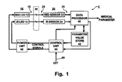
- Fig. 1 illustrates a portion of a medical device, incorporating light emitting devices, used to measure patient medical parameters.
- Fig. 1 is a block diagram of a system 1 employed by such a medical device for adjusting power employed by the medical device.
- system 1 a plurality 10 of light emitting devices 12, 14 produce respective light signals 15.
- the light signals 15 are passed through, or reflected off of, biological tissue 20.
- the resulting respective light signals 25, modified by passing through or being reflected off of the biological tissue 20, are received by a corresponding plurality 30 of light sensor devices 32, 34.
- the plurality 30 of light sensor devices 32, 34 convert the received light signals 25 into corresponding electrical signals 35.
- Respective output terminals of the plurality 30 of light sensor devices 32, 34 are coupled to corresponding input terminals of a data processor 40.
- a signal output terminal of the data processor 40 generates a medical parameter, and data processor 40 provides a further signal coupled to an input terminal of a control unit 50.
- a control output terminal of the data processor 40 is coupled to an input terminal of a parameter value store 42.
- An output terminal of the parameter value store 42 is coupled to a second input terminal of the control unit 50.
- Respective output terminals of the control unit 50 generates control signals, and are coupled to corresponding control input terminals of a power unit 60.
- Respective output terminals of the power unit 60 are coupled to corresponding input terminals of the plurality 10 of light emitting devices 12, 14.
- a control output terminal of the control unit 50 is coupled to a control input terminal of the data processor 40.
- An input terminal 55 is coupled to a source (not shown) of a control signal.
- the input terminal 55 is coupled to a control input terminal of the control unit 50.
- the power unit 60 powers the plurality 10 of light emitting devices 12, 14, responsive to the respective control signals.
- the control signals determine the power applied to the plurality 10 of light emitting devices 12, 14.
- the control unit 50 coupled to the power unit 60, provides the control signals.
- the control signals condition the power unit 60 to intermittently turn off at least one of the plurality 10 of light emitting devices 12, 14 in a power save mode.
- the control unit 50 initiates the power save mode in response to a determination that a patient medical parameter value measured by the medical device using an active light emitting device of the plurality of light emitting devices, is at a safe level.
- the system 1 may be implemented in a pulse oximeter medical device.
- a pulse oximeter produces successive blood oxygen saturation (e.g. SpO 2 ) and/or pulse rate (e.g. PLS) readings as the patient medical parameter values.
- the light emitting devices 10 are typically light emitting diodes (LEDs).
- the first LED 12 emits red light and the second LED 14 emits infrared (IR) light. They are typically time multiplexed to produce light signals 15 one at a time to produce a single SpO 2 and/or pulse rate reading.
- Respective signals 35 from the red 12 and IR 14 light sensors 32, 34 are read by the data processor 40 when the corresponding LED is on.
- the data processor 40 then processes those signals to calculate an SpO 2 and/or the pulse rate reading. Intermediate components are also typically calculated. For example, ac and dc components of the respective red and IR LED signals 35 are calculated and stored, and those components used to calculate the SpO 2 and/or pulse rate medical parameter.
- the system 1 enters a power save mode (described in more detail below) when a patient medical parameter value is at a safe level.
- the patient medical parameter value may be one measured by the medical device itself.
- the patient medical parameter value may be the blood oxygen saturation representative value.
- the control unit 50 determines that the patient medical parameter value (e.g. the blood oxygen saturation representative value) is at a safe level when it is above a predetermined threshold, for example.
- the patient medical parameter value may also be the pulse rate.
- the control unit 50 determines that the patient medical parameter value (e.g. the pulse rate) is at a safe level when it is within a predetermined range.
- the patient medical parameter value may indicate a change in the blood oxygen saturation representative value or a change in the pulse rate.
- the control unit 50 also determines that the patient medical parameter value (e.g. the change in blood oxygen saturation representative value or pulse rate) is at a safe level when it is less than a predetermined value.
- the patient medical parameter value may also be a rate-of-change of the blood oxygen saturation representative parameter or pulse rate.
- the control unit 50 further determines that the patient medical parameter value (e.g. rate-of-change of the blood oxygen saturation value or rate-of-change of the pulse rate) is at a safe level when it is within a predetermined range.
- the patient medical parameter value which controls entry to the power save mode may be provided from an external source, such as a separate patient monitoring device measuring other patient medical parameters.
- the patient medical parameter value may also be entered manually.
- An output terminal of such an external patient monitoring device (not shown) and/or manual input device (also not shown) may be coupled to the control unit 50 via the external terminal 55.
- the patient medical parameter value in such a case, may be at least one of: patient temperature; arterial blood pressure; a hematocrit level; and/or a cardiac index.
- One or more of the patient medical parameter values described above, and/or any other similar patient medical parameter value may be used by the control unit 50 to determine if the patient medical parameter value is at a safe level.
- the patient medical parameter value is determined to be at a safe level when the SpO 2 and pulse rate parameters are stable and within a predetermined range of acceptable values.
- Fig. 2 which illustrates the process of entering and terminating the power save mode in the system illustrated in Fig. 1.
- the SpO 2 reading should be between 90% and 100% and the pulse rate should be between 50 and 100 beats per minute (bpm).
- Stability is determined by the change and the rate-of-change in the SpO 2 and pulse rate values being less than a relatively low threshold.
- the acceptable range of SpO 2 and pulse rate values, and threshold levels for the change in these values may be adjusted by a user.
- the control unit 50 receives the SpO 2 and pulse rate values from the data processor 40, and calculates the change in those values and the rate-of-change of those values.
- both LEDs 12 and 14 are enabled in step 202.
- values for SpO 2 and pulse rate (PLS) medical parameters are calculated by the data processor 40 based on the signals 35 representing the received light from the LEDs 12, 14.
- PLS pulse rate
- step 206 patient stability is determined.
- step 206 the pulse rate value PLS is compared to low and high thresholds P L and P H , respectively, and the SpO 2 value is compared to low and high thresholds, S L and S H , respectively. If the PLS value is between P L and P H and the SpO 2 value is between S L and S H , then step 208 is performed, otherwise, the medical device remains in normal mode and operation returns to step 202.
- step 208 the change in the PLS value ( ⁇ PLS) is compared to a thresholds ⁇ P, and the change in the SpO 2 value ( ⁇ SpO 2 ) is compared to a threshold ⁇ S. If the ⁇ PLS value is less than the ⁇ P threshold, and the ⁇ SpO 2 value is less than the AS threshold, then step 210 is performed, otherwise, the medical device remains in normal mode and operation returns to step 202.
- the rate-of-change of the PLS value (ROC PLS) is compared to a thresholds min P ROC , and the rate-of-change in the SpO 2 value (ROC SpO 2 ) is compared to a threshold min S ROC . If the ROC SpO 2 value is less than the min S ROC threshold, and the ROC PLS value is less than the min P ROC threshold, then step 210 is performed, otherwise, the medical device remains in normal mode and operation returns to step 202.
- a check is made on the consistency of the signals 35, representing the light received from the plurality 10 of LEDs 12 and 14.
- Signal consistency may be represented by the signal-to-noise ratio of the received signal, by drift of signal components, such as an ac and/or dc component, or any other similar measure of signal consistency.
- step 212 the signal consistency of the signal 35 (SC RED ) representing the light received from the red LED 12 is compared to a threshold min SC RED . If the signal consistency of the red signal SC RED is greater than the threshold min SC RED , then step 214 is performed, otherwise, the medical device remains in normal mode and operation returns to step 202. Similarly, in step 212 the signal consistency of the signal 35 (SC IR ) representing the light received from the IR LED 14 is compared to a threshold min SC IR . If the signal consistency of the IR signal SC IR is greater than the threshold min SC IR , then the patient is considered to be stable and the signals consistent. In this case, the system 1 (Fig. 1) enters the power save mode and step 222 is performed, otherwise, the medical device remains in normal mode and operation returns to step 202.
- the control unit 50 (Fig. 1) provides control signals to the power unit 60 conditioning it to intermittently turn off at least first and second different LEDs 12, 14 of the plurality 10 of LEDs 12, 14 in the power save mode.
- step 222 one of the plurality 10 of LEDs is turned off. In this mode, when one LED (e.g. 12) is turned off, the other LED (e.g. 14) remains active. Prior to turning off an LED (e.g. 12), parameter values obtained using the active LED are stored in the parameter value store 42.
- step 224 the parameter values for the LED to be turned off are stored, and a reading is taken using the other, active, LED.
- parameter values resulting from e.g. intermediate calculations made by the data processor 40 (Fig. 1) related to the IR LED (e.g. 14) are stored in the parameter value store 42.
- the stored parameter values are retrieved from the parameter value store 42 and used together with the parameter values obtained using the active LED (e.g. the IR LED 14) to calculate the medical parameter, e.g. SpO 2 and/or pulse rate.
- the calculation of the medical parameter, i.e. SpO 2 and/or pulse rate are performed in step 224.
- the control unit 50 retrieves the stored parameter value from the parameter value store 42, and uses the stored parameter values obtained using the previously active LED (e.g. 14) together with a parameter values obtained using the active LED (e.g. 12) to determine that the patient medical parameter value measured by the medical device is remaining at a safe level while in the power save mode.
- the patient medical parameter value is considered at a safe level if the patient remains stable and the signal remains consistent.
- Block 225 checks signal consistency.
- the change in the dc level ⁇ DC of the active LED (e.g. 14) signal 35 is compared to a threshold ⁇ DC min . If ⁇ DC is less than the threshold ⁇ DC min then step 228 is activated. Otherwise, it is determined that the signal is not consistent and the power save mode is terminated by returning to step 202 where both LEDs are activated.
- the change in the ac level ⁇ AC of the active LED (e.g. 14) signal 35 is compared to a threshold ⁇ AC min . If ⁇ AC is less than the threshold ⁇ AC min then step 230 is activated. Otherwise, it is determined that the signal is not consistent and the power save mode is terminated by returning to step 202 where both LEDs are activated.
- step 235 patient stability is checked.
- the change in the SpO 2 parameter ⁇ SpO 2 is compared to a threshold.
- the threshold is 1%. If the change in the SpO 2 parameter ⁇ SpO 2 is less than 1%, then step 232 is activated. Otherwise, it is determined that the patient is not stable and the power save mode is terminated by returning to step 202 where both LEDs are activated.
- the change in the pulse rate parameter ⁇ PLS is compared to a threshold. In the illustrated embodiment, the threshold is also 1%. If the change in the PLS parameter ⁇ PLS is less than 1%, then it is determined that the patient remains stable and the signal remains consistent. In this case, the system remains in the power save mode by returning to step 222. Otherwise, it is determined that the patient is not stable and the power save mode is terminated by returning to step 202 where both LEDs are activated.
- the system remains in the power save mode for as long as the patient remains stable and the signals remain consistent.
- the system automatically terminates the power save mode, and returns to the normal mode. This may be done to reset the stored parameters for the LED which was turned off.
- the predetermined time duration may be user configurable
- an external patient monitor may supply patient medical parameters to the control unit 50 via the external terminal 55.
- the control unit 50 monitors the patient medical parameters from the external patient monitor, i.e. the medical parameters that are measured without using at least one of the plurality 10 of light emitting devices 12, 14.
- the control unit 50 terminates the power save mode and turns on the light emitting device (e.g. 14) of the plurality of light emitting devices which was previously turned off.
- Fig. 3 is a block diagram illustrating a portion of the processing which is performed in the data processor 40 according to the present invention.
- the light representative signals 35 are coupled to respective signal input terminals of time domain processes 302 and to a signal input terminal of an FFT process 304.
- An output terminal of the FFT process 304 is coupled to respective signal input terminals of frequency domain processes 306.
- a plurality of N time domain processes TD PROC 1, TD PROC 2, ... TD PROC N
- the light representative signals 35 are coupled to respective signal input terminals of the plurality 302 of time domain processes, TD PROC 1, TD PROC 2, ... TD PROC N.
- a plurality of N frequency domain processes, FD PROC 1, FD PROC 2, ... FD PROC N are illustrated.
- the output terminal of the FFT process 304 is coupled to respective signal input terminals of the plurality 306 of frequency domain processes 306, FD PROC 1, FD PROC 2, ... FD PROC N.
- the control signal from the control unit 50 (Fig. 1) to the data processor 40 is coupled to an input terminal of a control process 310.
- Respective output terminals of the control process 310 are coupled to corresponding control input terminals of the plurality 302 of time domain processes, TD PROC 1, TD PROC 2, ... TD PROC N, and the plurality 306 of frequency domain processes, FD PROC 1, FD PROC 2, ... FD PROC N.
- Respective control output terminals of the controller 310 are also coupled to corresponding control input terminals of the FFT process 304 and the sensitivity selector 308.
- the data processor 40 employs a plurality of different processing functions (TD PROC 1, TD PROC 2, ... TD PROC N; FD PROC 1, FD PROC 2, ... FD PROC N) for processing the data in the signals 35 (Fig. 1) derived using the plurality 10 of light emitting devices 12, 14 in determining the patient medical parameter value, e.g. SpO 2 , pulse rate, measured by the medical device.
- a subset 302 of the plurality of processing functions operate in the time domain.
- Another subset 304 of the plurality of processing functions operate in the frequency domain.
- the control unit 50 provides a control signal to the control process 310 in the data processor 40 for turning off at least one processing function of the plurality of processing functions (TD PROC 1, TD PROC 2, ...
- the power save mode may be initiated in response to a determination that the patient medical parameter (e.g. SpO 2 , pulse rate), measured by the medical device using the active light emitting device (e.g. 14) of the plurality 10 of light emitting devices 12, 14, is at a safe level. More specifically, in the illustrated embodiment, the power save mode is initiated in step 222 of Fig. 2.
- the patient medical parameter e.g. SpO 2 , pulse rate
- the power save mode is initiated in step 222 of Fig. 2.
- the predetermined function disablement procedure turns off at least one processing function (TD PROC 1, TD PROC 2, ... TD PROC N; FD PROC 1, FD PROC 2, ... FD PROC N) in response to a sensitivity determination.
- the sensitivity determination is used to turn off the function (TD PROC 1, TD PROC 2, ... TD PROC N; FD PROC 1, FD PROC 2, ... FD PROC N) having least effect in the determination of the patient medical parameter value (e.g. SpO 2 , pulse rate) measured by the medical device.
- the control unit 50 provides control signals 40 to the control process 310 for progressively turning off processing functions of the plurality of processing functions (TD PROC 1, TD PROC 2, ... TD PROC N; FD PROC 1, FD PROC 2, ... FD PROC N) in the power save mode in response to the sensitivity determinations.
- the sensitivity selector 310 operates as probability-based classifier.
- Such a selector 310 classifies the results from the plurality of processing functions (TD PROC 1, TD PROC 2, ... TD PROC N; FD PROC 1, FD PROC 2, ... FD PROC N), termed features, based on the calculated probability, termed sensitivity, of their being accurate estimates of the patient medical parameter, e.g. SpO 2 , pulse rate.
- the number of features (TD PROC 1, TD PROC 2, ... TD PROC N; FD PROC 1, FD PROC 2, ... FD PROC N) used for the classifier computation may be reduced without compromising performance.
- the decision to select a particular feature is based on the sensitivity of that feature.
- multiple possible outcomes e.g. SpO 2 readings and/or pulse rate frequencies
- a feature process assigns a probability value to the possible outcomes.
- the power of classification is computed for an individual feature process (TD PROC 1, TD PROC 2, ... TD PROC N; FD PROC 1, FD PROC 2, ... FD PROC N) to assess its sensitivity level S.
- an individual feature process TD PROC 1, TD PROC 2, ... TD PROC N; FD PROC 1, FD PROC 2, ... FD PROC N
- the process (TD PROC 1, TD PROC 2, ... TD PROC N; FD PROC 1, FD PROC 2, ... FD PROC N) with the lowest sensitivity level S is turned off and consequently not processed by the sensitivity selector 308.
- processes (TD PROC 1, TD PROC 2,... TD PROC N; FD PROC 1, FD PROC 2, ... FD PROC N) having the lowest sensitivity level S are progressively turned off. With fewer processes operating, power consumption by the data processor 40 is reduced.
- the control unit 50 (Fig. 1) provides a control signal to the control process 310 In the data processor 40 which conditions the FFT process 304 to reduce the processing required to produce the frequency domain samples in the power save mode. Specifically, the number of samples in the input and output sample set, and the rate at which conversion cycles are made may be controlled.
- the number of samples in the set of time domain samples (and corresponding frequency domain output samples) is reduced and/or the rate at which successive sets of time domain input samples are transformed into corresponding sets of frequency domain samples is reduced. Less power is consumed when fewer samples are transformed, and when the rate of conversion cycles is reduced.
- processing blocks in Fig. 3 represent executable procedures which may be executed by the data processor 40.
- these processing blocks may be implemented in hardware, firmware, software or any combination of the three.
- a medical device such as a pulse oximeter medical device
- a multifunction patient monitor device may include an ECG monitor, blood pressure monitor, temperature monitor, ventilation monitor, etc. in addition to the pulse oximeter monitor providing SpO 2 and pulse rate medical parameters.
- the pulse oximeter system uses the plurality 10 (Fig. 1) of light emitting devices 12, 14 to derive the SpO 2 and pulse rate patient medical parameters.
- the other medical devices in the multifunction monitor derive patient medical parameters (i.e. ECG lead signals, blood pressure, temperature, ventilation parameters, etc.) without using the plurality 10 of light emitting devices 12, 14.
- the control unit 50 may provide a control signal coupled to the power unit 60 for turning off the light emitting device in a power save mode for a predetermined time duration.
- the control unit 50 may further provide a control signal for turning off processing of data occurring in deriving the patient medical parameter (e.g. SpO 2 , pulse rate) using the light emitting device.
- the control unit 50 may instead provide a control signal turning off operation of the medical device functions which are unused in deriving the patient medical parameter (e.g. SpO 2 , pulse rate) that is measured without using the light emitting devices 12, 14 in response to a determination that the patient medical parameter value measured by the medical device using an active light emitting device (e.g.
- the control unit 50 monitors a patient medical parameter that is measured without using the light emitting devices 12, 14 (e.g. EKG, temperature, ventilation parameters, etc.) and in response to a determination that the monitored patient medical parameter value is outside of a predetermined range, terminates the power save mode and turns on the light emitting devices 12, 14 and the processing of data. In this manner, the power consumed by the pulse oximeter monitor may be eliminated or substantially reduced.
- a patient medical parameter that is measured without using the light emitting devices 12, 14 (e.g. EKG, temperature, ventilation parameters, etc.) and in response to a determination that the monitored patient medical parameter value is outside of a predetermined range, terminates the power save mode and turns on the light emitting devices 12, 14 and the processing of data. In this manner, the power consumed by the pulse oximeter monitor may be eliminated or substantially reduced.
Landscapes
- Health & Medical Sciences (AREA)
- Physics & Mathematics (AREA)
- Life Sciences & Earth Sciences (AREA)
- Biomedical Technology (AREA)
- Medical Informatics (AREA)
- Biophysics (AREA)
- Pathology (AREA)
- Engineering & Computer Science (AREA)
- Spectroscopy & Molecular Physics (AREA)
- Heart & Thoracic Surgery (AREA)
- Optics & Photonics (AREA)
- Molecular Biology (AREA)
- Surgery (AREA)
- Animal Behavior & Ethology (AREA)
- General Health & Medical Sciences (AREA)
- Public Health (AREA)
- Veterinary Medicine (AREA)
- Measurement Of The Respiration, Hearing Ability, Form, And Blood Characteristics Of Living Organisms (AREA)
- Laser Surgery Devices (AREA)
Applications Claiming Priority (1)
| Application Number | Priority Date | Filing Date | Title |
|---|---|---|---|
| US69761505P | 2005-07-08 | 2005-07-08 |
Publications (3)
| Publication Number | Publication Date |
|---|---|
| EP1741384A2 true EP1741384A2 (de) | 2007-01-10 |
| EP1741384A3 EP1741384A3 (de) | 2008-04-02 |
| EP1741384B1 EP1741384B1 (de) | 2009-11-11 |
Family
ID=37137527
Family Applications (1)
| Application Number | Title | Priority Date | Filing Date |
|---|---|---|---|
| EP06253582A Active EP1741384B1 (de) | 2005-07-08 | 2006-07-07 | System zur Leistungseinstellung für eine medizinische Vorrichtung |
Country Status (3)
| Country | Link |
|---|---|
| US (1) | US8116837B2 (de) |
| EP (1) | EP1741384B1 (de) |
| DE (1) | DE602006010270D1 (de) |
Cited By (1)
| Publication number | Priority date | Publication date | Assignee | Title |
|---|---|---|---|---|
| CN103222857A (zh) * | 2013-04-24 | 2013-07-31 | 华南理工大学 | 一种热辐射刺激保护装置 |
Families Citing this family (37)
| Publication number | Priority date | Publication date | Assignee | Title |
|---|---|---|---|---|
| US7764982B2 (en) | 2005-03-01 | 2010-07-27 | Masimo Laboratories, Inc. | Multiple wavelength sensor emitters |
| US20190357827A1 (en) | 2003-08-01 | 2019-11-28 | Dexcom, Inc. | Analyte sensor |
| US8219173B2 (en) | 2008-09-30 | 2012-07-10 | Abbott Diabetes Care Inc. | Optimizing analyte sensor calibration |
| US8224415B2 (en) | 2009-01-29 | 2012-07-17 | Abbott Diabetes Care Inc. | Method and device for providing offset model based calibration for analyte sensor |
| US9675290B2 (en) | 2012-10-30 | 2017-06-13 | Abbott Diabetes Care Inc. | Sensitivity calibration of in vivo sensors used to measure analyte concentration |
| US7630748B2 (en) | 2006-10-25 | 2009-12-08 | Abbott Diabetes Care Inc. | Method and system for providing analyte monitoring |
| US7559899B2 (en) * | 2006-04-12 | 2009-07-14 | Salutron, Inc. | Power saving techniques for continuous heart rate monitoring |
| US8265723B1 (en) | 2006-10-12 | 2012-09-11 | Cercacor Laboratories, Inc. | Oximeter probe off indicator defining probe off space |
| US8374665B2 (en) | 2007-04-21 | 2013-02-12 | Cercacor Laboratories, Inc. | Tissue profile wellness monitor |
| US8160900B2 (en) | 2007-06-29 | 2012-04-17 | Abbott Diabetes Care Inc. | Analyte monitoring and management device and method to analyze the frequency of user interaction with the device |
| US9560994B2 (en) | 2008-03-26 | 2017-02-07 | Covidien Lp | Pulse oximeter with adaptive power conservation |
| US8591410B2 (en) | 2008-05-30 | 2013-11-26 | Abbott Diabetes Care Inc. | Method and apparatus for providing glycemic control |
| US8924159B2 (en) | 2008-05-30 | 2014-12-30 | Abbott Diabetes Care Inc. | Method and apparatus for providing glycemic control |
| US10058274B2 (en) * | 2008-06-30 | 2018-08-28 | Medtronic, Inc. | Tissue perfusion sensor control |
| US20100030040A1 (en) | 2008-08-04 | 2010-02-04 | Masimo Laboratories, Inc. | Multi-stream data collection system for noninvasive measurement of blood constituents |
| WO2010003134A2 (en) | 2008-07-03 | 2010-01-07 | Masimo Laboratories, Inc. | Protrusion, heat sink, and shielding for improving spectroscopic measurement of blood constituents |
| US9326707B2 (en) | 2008-11-10 | 2016-05-03 | Abbott Diabetes Care Inc. | Alarm characterization for analyte monitoring devices and systems |
| EP2494323A4 (de) | 2009-10-30 | 2014-07-16 | Abbott Diabetes Care Inc | Verfahren und vorrichtung zur erkennung unnormaler hypoglykämischer werte |
| US9839381B1 (en) | 2009-11-24 | 2017-12-12 | Cercacor Laboratories, Inc. | Physiological measurement system with automatic wavelength adjustment |
| CN102421355B (zh) * | 2010-01-29 | 2014-07-16 | 北京超思电子技术股份有限公司 | 一种在手指处测量血氧的方法及指夹式血氧测量仪 |
| US20110213217A1 (en) * | 2010-02-28 | 2011-09-01 | Nellcor Puritan Bennett Llc | Energy optimized sensing techniques |
| US10092229B2 (en) | 2010-06-29 | 2018-10-09 | Abbott Diabetes Care Inc. | Calibration of analyte measurement system |
| EP3575796B1 (de) | 2011-04-15 | 2020-11-11 | DexCom, Inc. | Erweiterte analytsensorkalibrierung und fehlererkennung |
| US9622691B2 (en) | 2011-10-31 | 2017-04-18 | Abbott Diabetes Care Inc. | Model based variable risk false glucose threshold alarm prevention mechanism |
| US9241676B2 (en) | 2012-05-31 | 2016-01-26 | Covidien Lp | Methods and systems for power optimization in a medical device |
| US9241643B2 (en) | 2012-05-31 | 2016-01-26 | Covidien Lp | Methods and systems for power optimization in a medical device |
| WO2014052136A1 (en) | 2012-09-26 | 2014-04-03 | Abbott Diabetes Care Inc. | Method and apparatus for improving lag correction during in vivo measurement of analyte concentration with analyte concentration variability and range data |
| US9351688B2 (en) | 2013-01-29 | 2016-05-31 | Covidien Lp | Low power monitoring systems and method |
| US9474475B1 (en) | 2013-03-15 | 2016-10-25 | Abbott Diabetes Care Inc. | Multi-rate analyte sensor data collection with sample rate configurable signal processing |
| US10433773B1 (en) | 2013-03-15 | 2019-10-08 | Abbott Diabetes Care Inc. | Noise rejection methods and apparatus for sparsely sampled analyte sensor data |
| WO2014152034A1 (en) | 2013-03-15 | 2014-09-25 | Abbott Diabetes Care Inc. | Sensor fault detection using analyte sensor data pattern comparison |
| US9848808B2 (en) * | 2013-07-18 | 2017-12-26 | Cas Medical Systems, Inc. | Method for spectrophotometric blood oxygenation monitoring |
| US10188330B1 (en) | 2014-02-05 | 2019-01-29 | Covidien Lp | Methods and systems for determining a light drive parameter limit in a physiological monitor |
| EP4151150B1 (de) | 2014-03-30 | 2025-08-27 | Abbott Diabetes Care Inc. | Verfahren und gerät zum bestimmen von mahlzeitenbeginn und peak-ereignissen in analytischen überwachungssystemen |
| DE102017121715A1 (de) * | 2017-09-19 | 2019-03-21 | Osram Opto Semiconductors Gmbh | Verfahren zum Messen einer Pulsfrequenz, Pulsfrequenzmesser und Computerprogrammprodukt |
| EP3700416B1 (de) | 2017-10-24 | 2024-06-26 | Dexcom, Inc. | Vorverbundene analytsensoren |
| US11331022B2 (en) | 2017-10-24 | 2022-05-17 | Dexcom, Inc. | Pre-connected analyte sensors |
Citations (1)
| Publication number | Priority date | Publication date | Assignee | Title |
|---|---|---|---|---|
| US5924979A (en) | 1996-02-09 | 1999-07-20 | Nellcor Puritan Bennett Incorporated | Medical diagnostic apparatus with sleep mode |
Family Cites Families (6)
| Publication number | Priority date | Publication date | Assignee | Title |
|---|---|---|---|---|
| US4892101A (en) | 1986-08-18 | 1990-01-09 | Physio-Control Corporation | Method and apparatus for offsetting baseline portion of oximeter signal |
| US4859057A (en) | 1987-10-13 | 1989-08-22 | Lawrence Medical Systems, Inc. | Oximeter apparatus |
| US5069214A (en) | 1988-12-14 | 1991-12-03 | Gms Engineering Corporation | Flash reflectance oximeter |
| EP0872210B1 (de) | 1997-04-18 | 2006-01-04 | Koninklijke Philips Electronics N.V. | Intermittierende Messung der arteriellen Sauerstoffsättigung von Hämoglobin |
| US6697658B2 (en) * | 2001-07-02 | 2004-02-24 | Masimo Corporation | Low power pulse oximeter |
| US6863652B2 (en) | 2002-03-13 | 2005-03-08 | Draeger Medical Systems, Inc. | Power conserving adaptive control system for generating signal in portable medical devices |
-
2006
- 2006-07-07 DE DE602006010270T patent/DE602006010270D1/de active Active
- 2006-07-07 EP EP06253582A patent/EP1741384B1/de active Active
- 2006-07-07 US US11/482,509 patent/US8116837B2/en active Active
Patent Citations (1)
| Publication number | Priority date | Publication date | Assignee | Title |
|---|---|---|---|---|
| US5924979A (en) | 1996-02-09 | 1999-07-20 | Nellcor Puritan Bennett Incorporated | Medical diagnostic apparatus with sleep mode |
Cited By (1)
| Publication number | Priority date | Publication date | Assignee | Title |
|---|---|---|---|---|
| CN103222857A (zh) * | 2013-04-24 | 2013-07-31 | 华南理工大学 | 一种热辐射刺激保护装置 |
Also Published As
| Publication number | Publication date |
|---|---|
| US8116837B2 (en) | 2012-02-14 |
| EP1741384B1 (de) | 2009-11-11 |
| US20070038049A1 (en) | 2007-02-15 |
| DE602006010270D1 (de) | 2009-12-24 |
| EP1741384A3 (de) | 2008-04-02 |
Similar Documents
| Publication | Publication Date | Title |
|---|---|---|
| US8116837B2 (en) | System for adjusting power employed by a medical device | |
| US10959652B2 (en) | Low power pulse oximeter | |
| US6863652B2 (en) | Power conserving adaptive control system for generating signal in portable medical devices | |
| EP0872210B1 (de) | Intermittierende Messung der arteriellen Sauerstoffsättigung von Hämoglobin | |
| US7355512B1 (en) | Parallel alarm processor | |
| US8792949B2 (en) | Reducing nuisance alarms | |
| EP3383256B1 (de) | Systeme und verfahren zur detektion der verwendung von photoplethysmographischen vorrichtungen | |
| US20120116193A1 (en) | System for Adjusting Power Employed by a Medical Device | |
| US8574162B2 (en) | Systems and methods for detecting pulses | |
| US7650244B2 (en) | Method and device for monitoring analyte concentration by determining its progression in the living body of a human or animal | |
| US8932219B2 (en) | Systems and methods for monitoring heart rate and blood pressure correlation | |
| US8221326B2 (en) | Detection of oximetry sensor sites based on waveform characteristics | |
| JPH10314150A5 (de) | ||
| US11872062B2 (en) | Medical device and method for controlling medical device, and storage medium | |
| EP4696234A1 (de) | Verfahren und vorrichtung zur oximeterregelung | |
| US10993644B2 (en) | SpO2 system and method | |
| JP2004016279A (ja) | 体動検出装置および体動検出方法 | |
| EP3906847A1 (de) | Verfahren, vorrichtung und system zur bestimmung einer verschiebung des herzzeitvolumens |
Legal Events
| Date | Code | Title | Description |
|---|---|---|---|
| PUAI | Public reference made under article 153(3) epc to a published international application that has entered the european phase |
Free format text: ORIGINAL CODE: 0009012 |
|
| AK | Designated contracting states |
Kind code of ref document: A2 Designated state(s): AT BE BG CH CY CZ DE DK EE ES FI FR GB GR HU IE IS IT LI LT LU LV MC NL PL PT RO SE SI SK TR |
|
| AX | Request for extension of the european patent |
Extension state: AL BA HR MK YU |
|
| PUAL | Search report despatched |
Free format text: ORIGINAL CODE: 0009013 |
|
| AK | Designated contracting states |
Kind code of ref document: A3 Designated state(s): AT BE BG CH CY CZ DE DK EE ES FI FR GB GR HU IE IS IT LI LT LU LV MC NL PL PT RO SE SI SK TR |
|
| AX | Request for extension of the european patent |
Extension state: AL BA HR MK YU |
|
| 17P | Request for examination filed |
Effective date: 20080916 |
|
| 17Q | First examination report despatched |
Effective date: 20081017 |
|
| AKX | Designation fees paid |
Designated state(s): DE FR GB |
|
| GRAP | Despatch of communication of intention to grant a patent |
Free format text: ORIGINAL CODE: EPIDOSNIGR1 |
|
| GRAS | Grant fee paid |
Free format text: ORIGINAL CODE: EPIDOSNIGR3 |
|
| GRAA | (expected) grant |
Free format text: ORIGINAL CODE: 0009210 |
|
| AK | Designated contracting states |
Kind code of ref document: B1 Designated state(s): DE FR GB |
|
| REG | Reference to a national code |
Ref country code: GB Ref legal event code: FG4D |
|
| REF | Corresponds to: |
Ref document number: 602006010270 Country of ref document: DE Date of ref document: 20091224 Kind code of ref document: P |
|
| PLBE | No opposition filed within time limit |
Free format text: ORIGINAL CODE: 0009261 |
|
| STAA | Information on the status of an ep patent application or granted ep patent |
Free format text: STATUS: NO OPPOSITION FILED WITHIN TIME LIMIT |
|
| 26N | No opposition filed |
Effective date: 20100812 |
|
| GBPC | Gb: european patent ceased through non-payment of renewal fee |
Effective date: 20100707 |
|
| REG | Reference to a national code |
Ref country code: FR Ref legal event code: ST Effective date: 20110331 |
|
| PG25 | Lapsed in a contracting state [announced via postgrant information from national office to epo] |
Ref country code: FR Free format text: LAPSE BECAUSE OF NON-PAYMENT OF DUE FEES Effective date: 20100802 |
|
| PG25 | Lapsed in a contracting state [announced via postgrant information from national office to epo] |
Ref country code: GB Free format text: LAPSE BECAUSE OF NON-PAYMENT OF DUE FEES Effective date: 20100707 |
|
| REG | Reference to a national code |
Ref country code: DE Ref legal event code: R082 Ref document number: 602006010270 Country of ref document: DE Representative=s name: UEXKUELL & STOLBERG, DE Ref country code: DE Ref legal event code: R082 Ref document number: 602006010270 Country of ref document: DE Representative=s name: HASELTINE LAKE LLP, DE |
|
| REG | Reference to a national code |
Ref country code: DE Ref legal event code: R082 Ref document number: 602006010270 Country of ref document: DE Representative=s name: HASELTINE LAKE LLP, DE |
|
| REG | Reference to a national code |
Representative=s name: HL KEMPNER PATENTANWALT, RECHTSANWALT, SOLICIT, DE Ref country code: DE Ref legal event code: R082 Ref document number: 602006010270 Country of ref document: DE Representative=s name: HL KEMPNER PATENTANWAELTE, SOLICITORS (ENGLAND, DE Ref country code: DE Ref legal event code: R082 Ref document number: 602006010270 Country of ref document: DE Ref country code: DE Ref legal event code: R082 Ref document number: 602006010270 Country of ref document: DE Representative=s name: HL KEMPNER PARTG MBB, DE |
|
| REG | Reference to a national code |
Ref country code: DE Ref legal event code: R082 Ref document number: 602006010270 Country of ref document: DE Representative=s name: HL KEMPNER PATENTANWAELTE, SOLICITORS (ENGLAND, DE Ref country code: DE Ref legal event code: R082 Ref document number: 602006010270 Country of ref document: DE Ref country code: DE Ref legal event code: R081 Ref document number: 602006010270 Country of ref document: DE Owner name: DRAEGERWERK AG & CO. KGAA, DE Free format text: FORMER OWNER: DRAEGER MEDICAL SYSTEMS, INC., ANDOVER, MASS., US Ref country code: DE Ref legal event code: R082 Ref document number: 602006010270 Country of ref document: DE Representative=s name: HL KEMPNER PARTG MBB, DE |
|
| REG | Reference to a national code |
Ref country code: DE Ref legal event code: R082 Ref document number: 602006010270 Country of ref document: DE Representative=s name: HL KEMPNER PATENTANWAELTE, SOLICITORS (ENGLAND, DE Ref country code: DE Ref legal event code: R082 Ref document number: 602006010270 Country of ref document: DE Representative=s name: HL KEMPNER PARTG MBB, DE |
|
| PGFP | Annual fee paid to national office [announced via postgrant information from national office to epo] |
Ref country code: DE Payment date: 20250728 Year of fee payment: 20 |