EP1741013B1 - Verfahren zur schätzung einer dauer, während der ein rolladenstellglied ausgeschaltet ist - Google Patents
Verfahren zur schätzung einer dauer, während der ein rolladenstellglied ausgeschaltet ist Download PDFInfo
- Publication number
- EP1741013B1 EP1741013B1 EP05718524A EP05718524A EP1741013B1 EP 1741013 B1 EP1741013 B1 EP 1741013B1 EP 05718524 A EP05718524 A EP 05718524A EP 05718524 A EP05718524 A EP 05718524A EP 1741013 B1 EP1741013 B1 EP 1741013B1
- Authority
- EP
- European Patent Office
- Prior art keywords
- actuator
- microcontroller
- memory
- mem
- cpu
- Prior art date
- Legal status (The legal status is an assumption and is not a legal conclusion. Google has not performed a legal analysis and makes no representation as to the accuracy of the status listed.)
- Active
Links
Images


Classifications
-
- G—PHYSICS
- G05—CONTROLLING; REGULATING
- G05B—CONTROL OR REGULATING SYSTEMS IN GENERAL; FUNCTIONAL ELEMENTS OF SUCH SYSTEMS; MONITORING OR TESTING ARRANGEMENTS FOR SUCH SYSTEMS OR ELEMENTS
- G05B19/00—Programme-control systems
- G05B19/02—Programme-control systems electric
- G05B19/18—Numerical control [NC], i.e. automatically operating machines, in particular machine tools, e.g. in a manufacturing environment, so as to execute positioning, movement or co-ordinated operations by means of programme data in numerical form
- G05B19/414—Structure of the control system, e.g. common controller or multiprocessor systems, interface to servo, programmable interface controller
-
- G—PHYSICS
- G05—CONTROLLING; REGULATING
- G05B—CONTROL OR REGULATING SYSTEMS IN GENERAL; FUNCTIONAL ELEMENTS OF SUCH SYSTEMS; MONITORING OR TESTING ARRANGEMENTS FOR SUCH SYSTEMS OR ELEMENTS
- G05B19/00—Programme-control systems
- G05B19/02—Programme-control systems electric
- G05B19/04—Programme control other than numerical control, i.e. in sequence controllers or logic controllers
- G05B19/042—Programme control other than numerical control, i.e. in sequence controllers or logic controllers using digital processors
Definitions
- the invention relates to a method of estimating a duration during which an actuator intended to maneuver a mobile screen or a mobile equipment for closing, occultation or solar protection of a building is not powered according to the preamble of claim 1.
- the invention also relates to an actuator for implementing the method according to the invention.
- the actuators used for the maneuvering of closing elements, occultation or solar protection of the building are often powered by the alternative network of distribution of electrical energy. In some configurations, it is very interesting to measure the time during which the actuator is not powered. Indeed, one or more short periods of non-power of the actuator can be used to send to it a command of a particular type.
- the non-power times for sending a command of a particular type are of the order of one second or several seconds.
- Patent is known US 6,078,159 a device for operating a closure element.
- the device comprises a control box provided with two buttons respectively for controlling the movements of a movable element in a first direction and in a second direction.
- To place this device in a configuration mode it is necessary to actuate at least two times one or the other of the keys in a predefined time range and less than an actuation duration allowing the control of the movement of the mobile element.
- the microcontroller will not have the means to distinguish a voluntary short cut, having a predetermined duration and repeated for example twice for confirmation, accidental break of very short duration or, on the contrary, very long duration.
- the object of the invention is to provide a method for overcoming these disadvantages.
- the method according to the invention makes it possible very simple means of estimating the duration during which the actuator is not powered.
- the estimation method according to the invention is characterized by the characterizing part of claim 1.
- the actuator according to the invention is defined by claim 5.
- the actuator may include a diode connected in series with the electrical energy storage element between the output terminals of the voltage converter.
- the microcontroller may comprise an input terminal connected, on the one hand, to a time measuring circuit including the clock and the first memory and, on the other hand, to an output terminal of the voltage converter.
- the figure 1 is a circuit diagram of a first embodiment of an actuator for implementing the method according to the invention.
- the figure 2 is a circuit diagram of a second embodiment of an actuator for implementing the method according to the invention.
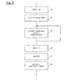
- the figure 3 is a flowchart describing the main steps of a first embodiment of the method according to the invention.
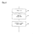
- the figure 4 is a flowchart describing the main steps of a second embodiment of the method according to the invention.
- the installation 1 represented at figure 1 comprises an actuator ACT with a motor MOT driving a mobile equipment of the building called load LD in a first or a second direction of movement, for example in a direction of rise or descent for a shutter or in a horizontal direction on the right or in a horizontal direction to the left for a sliding panel.
- the actuator is connected to the AC electrical distribution network, which comprises a neutral conductor AC-N and a phase conductor AC-H. This connection is made at the neutral conductor via a NO terminal.
- the connection to the phase conductor is provided by a first phase terminal UP and a second phase terminal DN, connectable to the phase conductor AC-H according to the state of a control switch K1.
- the control switch comprises two switches K11 and K12, for example pushbuttons. Depending on whether the user wants to operate the equipment in one direction or the other, he or she presses the K11 switch or the K12 switch.
- the switches K11 and K12 are necessarily activated during the entire duration of the movement, so as to allow the supply of the actuator through one or other of these switches.
- the "closed" states of the switches K11 and K12 are respectively detected by a first sensor CS1 and a second sensor CS2, consisting of current sensing devices, optocouplers or simple electronic assemblies allowing the transformation of a high AC voltage in DC voltage of sufficiently low value to be used logically, for example 5 volts.
- sensors are preferably current sensors but they may equally well be potentiometric dividers with rectifying diode and filtering capacitor.
- the actuator comprises an MCU control unit comprising a CPU microcontroller and a PSU power converter.
- the PSU power converter provides a DC voltage between two output lines VCC and GND.
- the potential of the ground line GND is referenced to 0 and that of the positive line VCC is then + Vcc, for example +5 volts. This continuous potential is applied to different circuits of the MCU control unit to power them.
- the input of the PSU power converter is capable of being connected to the AC-H phase conductor via two wires, which are connected to the first phase terminal UP and the second phase terminal DN.
- the sensors CS1 and CS2 can also be located upstream of the son supplying the PSU power converter, that is to say be interposed between the terminals UP or DN and the power supply son of the power converter PSU.
- the signals coming from the sensors CS1 and CS2 are applied to a first input I1 and to a second input I2 of the microcontroller CPU and determine, according to their origin, whether the order applied is an order of maneuver in the first direction or in the second direction or if he results from a combination of presses on switches K11 and K12 which must be interpreted as a particular order.
- the commands can also be received by an RFR radio receiver and transmitted to the microcontroller by an RFC serial line, applied to a fourth input 14 of the CPU microcontroller.
- the microcontroller CPU comprises a first output 01 and a second output 02 connected to a switching unit RLU by a first switching input RL1 and a second switching input RL2.
- the microcontroller CPU activates the first output 01 or the second output 02 so as to actuate for example relays contained in the switching unit RLU.
- the relays are of the electromagnetic type or static type.
- the switching unit allows the connection of the motor to the phase conductor AC-H, via the switch K1 via the first phase terminal UP or the second phase terminal DN and through the sensors CS1 or CS2. which causes a negligible voltage drop.
- the potential of the conductor referenced UP ' can be likened to the potential of the phase terminal UP
- the potential of the conductor referenced DN' can be likened to the potential of the phase terminal DN.
- MOT motor is a single-phase induction motor with permanent phase shift capacitor, comprising two windings W1 and W2 and a capacitor CM.
- the motor is connected on the one hand to the neutral conductor AC-N, via a connection to the neutral terminal N0, and on the other hand to the phase conductor AC-H, via the RLU switching unit whose outputs P1 and P2 are connected to inputs UP ', DN' according to the state of inputs RL1 and RL2 of the switching unit.
- a mechanical gearbox can be integrated in the drive train between the electric motor and the mobile equipment to be maneuvered.
- a position sensor can be integrated into the mobile equipment and deliver a position signal thereof applied to a fifth input I5 of the microcontroller CPU, via a line POS.
- the microcontroller CPU comprises a time measuring circuit TMR whose trigger input TRG constitutes a third input 13 of the microcontroller. This input also activates a different interrupt program depending on whether it switches from high (1) to low (0) or vice versa.
- the time measuring circuit TMR comprises, as shown in FIG. figure 1 , a CLK clock connected to a CNT counter. This counter is incremented by the pulses from the clock CLK. The output of the counter CNT is assimilated to a memory. Indeed, between two clock pulses, the value of this counter remains unchanged.
- the memory MEM is therefore the part of the counter CNT in which the current value reached by the counter is stored.
- the microcontroller is powered between a grounded terminal GND and a power supply terminal VDD connected to the positive line VCC through a diode D1.
- a supercapacitor SC1 is disposed between the terminals VDD and GND. When the latter has been loaded under the voltage + Vcc delivered by the PSU converter, it ensures, for a limited period of time at least greater than a predetermined maximum duration TMAX, the supply of the microcontroller at least in a low activity mode during which the TMR time measuring circuit is operational.
- the microcontroller also comprises at least one FLG memory storage location which makes it possible to keep at least one piece of information on a very long period of non-power supply.
- This memory FLG is for example constituted by an electrically erasable and programmable read-only memory, or simply a very low-power memory supplied with the residual voltage of the supercapacitor SC1 or by an independent battery, not shown.
- a first embodiment of the method according to the invention is represented by the flow chart of the figure 3 .
- a transition from the high state (1) to the low state (0) of the trigger input TRG is detected, this transition being the result of an interruption of the power supply. of the actuator.
- the stored memory location FLG is initialized by assigning it a logic low state.
- the counter CNT (thus the memory MEM giving the value of the counter CNT) is also initialized and the TMR circuit for time measurement is activated so that the counter CNT takes into account the pulses of the clock CLK.
- a third step 32 the value indicated by the counter CNT of the time measuring circuit TMR is continuously tested. As soon as this value is greater than a predetermined value TMAX, we assign to the memory location FLG saved a logic high state and we switch the microcontroller in a sleep mode in which it consumes only the energy necessary to keep the information stored in its memories.
- a transition is detected from the low state (0) to the high state (1) of the trigger input TRG, this transition being the result of a new connection of the actuator to the power supply.
- This step may be constituted by the awakening of the CPU microcontroller due to the appearance of a voltage on the VDD input.
- a step 41 the state of the saved memory location FLG is read.
- a step 42 the value stored in the saved memory location FLG is tested. If this value corresponds to a high state, the supply cutoff duration TOFF is set to a value greater than the predetermined maximum duration value TMAX.
- TOFF supply cut-off time can thus be framed between two values. It should be noted, however, that the microcontroller remaining partially active for at least one TMAX duration, any power failure of lesser duration can be processed without saving information in the stored memory.
- no stored memory location is used.
- the supercapacitor SC1 is dimensioned during the design of the control unit MCU so that it can only supply the microcontroller for a time slightly greater than the sum of the predetermined maximum duration TMAX and the time required to process TOFF measurement information. Under these conditions, the restoration of the supply voltage before the TMAX delay causes the simple continuation of the program: for example, a measurement cycle of the supply time is activated.
- a transition from the high state (1) to the low state (0) of the trigger input TRG is detected, this transition being the result of an interruption of the supply of the actuator.
- a second step 51 the counter CNT (thus the memory MEM giving the value of the counter CNT) is initialized and the time measuring circuit TMR is activated so that the counter CNT takes into account the pulses of the clock. CLK.
- a step 52 when a transition is detected from the low state (0) to the high state (1) of the trigger input TRG, resulting from a new connection of the actuator to the source of power supply, the contents of the time measuring circuit TMR are read. If the content of the TMR circuit is a particular reset value, it can be deduced that the circuit was reset between step 51 and step 52 due to a power failure of the microcontroller and that the power supply interruption of the actuator was longer than the predetermined time TMAX. In the opposite case, the value read corresponds to the duration TOFF of interruption of the supply of the actuator.
- This second embodiment of the method is capable of variants.
- the TMAX value can be recorded in the time measurement circuit and decrement this value to zero.
- the installation 1 ' represented at figure 2 , differs from the previously described installation in that the MDC motor of the actuator is of the DC type.
Landscapes
- Engineering & Computer Science (AREA)
- Physics & Mathematics (AREA)
- General Physics & Mathematics (AREA)
- Automation & Control Theory (AREA)
- Human Computer Interaction (AREA)
- Manufacturing & Machinery (AREA)
- Operating, Guiding And Securing Of Roll- Type Closing Members (AREA)
- Measuring Fluid Pressure (AREA)
- Air Bags (AREA)
- Control Of Ac Motors In General (AREA)
- Shutter-Related Mechanisms (AREA)
- Shutters For Cameras (AREA)
- Measurement Of Unknown Time Intervals (AREA)
- Charge And Discharge Circuits For Batteries Or The Like (AREA)
Claims (7)
- Verfahren zum Schätzen einer Dauer, während der ein Betätigungsgerät (AST), das zum Betätigen einer beweglichen Abschirmung oder einer beweglichen Schliess-, Verdunkelungs- oder Sonnenschutzeinrichtung (LD) eines Gebäudes bestimmt ist, nicht gespeist wird, wobei das Betätigungsgerät (AST) folgendes aufweist:- wenigstens zwei Klemmen (UP, DN, NO) zum Anschluss des Betätigungsgeräts an eine Spannungsquelle (AC-H, AC-N),- einen Elektromotor (MOT; MDC),- eine Steuereinheit (MCU), die mit Mitteln (RLU; PWU) zum Speisen des Motors aus der Spannungsquelle (AC-H, AC-N) verbunden ist und folgendes umfasst:dadurch gekennzeichnet, dass es die folgenden Schritte umfasst:- einen Spannungsumformer (PSU), dessen Ausgang eine Mikrokontrolleinheit (CPU) speist, welche die Mittel (RLU; PWU) zum Speisen des Motors (MOT; MDC) steuert und einen Zeitgeber (CLK) sowie wenigsens einen ersten Speicher (MEM) hat, und- ein Element (SC1) zum Speichern elektrischer Energie, das vom Spannungsumformer (PSU) geladen wird und zwischen die Speiseklemmen der Mikrokontrolleinheit (CPU) geschaltet ist,- Laden des Energiespeicherelements (SC1),- Beenden der Speisung des Betätigungsgeräts (ACT),- Speisen der Mikrokontrolleinheit (CPU) dank der Energie des Speicherelements (SC1), Initialisieren des oder der Speicher (MEM, FLG), dann Modifizieren des Inhalts des ersten Speichers (MEM) dank des Zeitgebers (CLK),- wenn die Mikrokontrolleinheit durch das Speicherelement (SC1) während einer Dauer gespeist wird, die länger ist als eine vorbestimmte Dauer (TMAX), Speichern eines besonderen Werts im ersten Speicher (MEM) oder in einem der Speicher (MEM, FLG),- Speisen des Betätigungsgeräts (ACT),- Lesen des im Speicher (MEM, FLG) gespeicherten Werts,- aus diesem Wert ableiten, ob die Dauer, die das Ereignis des zweiten Schritts vom Ereignis des fünften Schritts trennt, grösser oder kleiner als der Wert der vorbestimmten Dauer (TMAX) ist.
- Verfahren nach Anspruch 1, dadurch gekennzeichnet, dass der Schritt, bei dem ein besonderer Wert im ersten Speicher (MEM) gespeichert wird, durch das Auftreten des vorbestimmten Maximalwerts (TMAX) im Speicher (MEM) ausgelöst wird.
- Verfahren nach Anspruch 1, dadurch gekennzeichnet, dass der Schritt, bei dem ein besonderer Wert im Speicher (FLG) gespeichert wird, durch eine Unterbrechung der Speisung der Mikrokontrolleinheit (CPU) ausgelöst wird.
- Verfahren nach Anspruch 1 oder 2, dadurch gekennzeichnet, dass es vor dem Schritt, bei dem das Betätigungsgerät gespeist wird, einen Schritt des Desaktivierens der Mikrokontrolleinheit (CPU) umfasst und dass es nach dem Schritt, bei dem das Betätigungsgerät gespeist wird, einen Schritt des Aktivierens der Mikrokontrolleinheit (CPU) umfasst.
- Betätigungsgerät (ACT) zum Betätigen einer beweglichen Abschirmung oder einer beweglichen Schliess-, Verdunkelungs- oder Sonnenschutzeinrichtung (LD) eines Gebäudes, wobei dieses Betätigungsgerät (ACT) folgendes aufweist:- wenigstens zwei Klemmen (UP, DN, NO) zum Anschluss an eine Spannungsquelle (AC-H. AC-N),- einen Elektromotor (MOT; MDC),- eine Steuereinheit (MCU), die mit Mitteln (RLU; PWU) zum Speisen des Motors aus der Spannungsquelle (AC-H, AV-N) verbunden ist,- einen Spannungsumformer (PSU), dessen Ausgang eine Mikrokontrolleinheit (CPU) speist, welche die Mittel (RLU; PWU) zum Speisen des Motors (MOT; MDC) steuert und einen Zeitgeber (CLK) sowie wenigstens einen Speicher (MEM; FLG) aufweist,- ein Element (SC1) zum Speichern elektrischer Energie, welches vom Spannungsumformer (PSU) geladen wird und zwischen die Speiseklemmen der Mikrokontrolleinheit (CPU) geschaltet ist,dadurch gekennzeichnet, dass es Software-Mittel zum Durchführen des Verfahrend nach einem der vorangehenden Ansprüche aufweist.
- Betätigungsgerät (ACT) nach Anspruch 5, dadurch gekennzeichnet, dass es eine Diode (D1) aufweist, die in Reihe mit dem Element (SC1) zum Speichern elektrischer Energie zwischen die Klemmen (VCC, GND) des Ausgangs des Spannungsumformers (PSU) geschaltet ist.
- Betätigungsgerät (ACT) nach Anspruch 5 oder 6, dadurch gekennzeichnet, dass die Mikrokontrolleinheit (CPU) eine Eingangsklemme (13) hat, die einerseits an eine den Zeitgeber (CLK) und den ersten Speicher (MEM) einschliessende Zeitmessschaltung (TMR) und andererseits an eine Ausgangsklemme (VCC) des Spannungsumformers (PSU) angeschlossen ist.
Applications Claiming Priority (2)
| Application Number | Priority Date | Filing Date | Title |
|---|---|---|---|
| FR0404450A FR2869471B1 (fr) | 2004-04-27 | 2004-04-27 | Procede d'estimation d'une duree pendant laquelle un actionneur de volet roulant n'est pas alimente et dispositif pour sa mise en oeuvre |
| PCT/IB2005/001129 WO2005104330A2 (fr) | 2004-04-27 | 2005-04-21 | Procede d'estimation d'une duree pendant laquelle un actionneur de volet roulant est hors tension |
Publications (2)
| Publication Number | Publication Date |
|---|---|
| EP1741013A2 EP1741013A2 (de) | 2007-01-10 |
| EP1741013B1 true EP1741013B1 (de) | 2008-03-26 |
Family
ID=34945451
Family Applications (1)
| Application Number | Title | Priority Date | Filing Date |
|---|---|---|---|
| EP05718524A Active EP1741013B1 (de) | 2004-04-27 | 2005-04-21 | Verfahren zur schätzung einer dauer, während der ein rolladenstellglied ausgeschaltet ist |
Country Status (5)
| Country | Link |
|---|---|
| EP (1) | EP1741013B1 (de) |
| AT (1) | ATE390657T1 (de) |
| DE (1) | DE602005005660T2 (de) |
| FR (1) | FR2869471B1 (de) |
| WO (1) | WO2005104330A2 (de) |
Families Citing this family (1)
| Publication number | Priority date | Publication date | Assignee | Title |
|---|---|---|---|---|
| FR2898221B1 (fr) * | 2006-03-06 | 2008-08-01 | Somfy Sas | Procede de commande et de test d'une installation domotique filaire |
Family Cites Families (6)
| Publication number | Priority date | Publication date | Assignee | Title |
|---|---|---|---|---|
| EP0038877B1 (de) * | 1980-04-28 | 1985-06-26 | Paul Rouet | Verfahren und Anlage zur Nachrichten- und Steuerübertragung auf ein Versorgungsnetz für Wechselstrom |
| EP0724208A1 (de) * | 1995-01-24 | 1996-07-31 | Hewlett-Packard Company | Steuerung des Netzteillieferungssystems in einem Rechner |
| DE19616066B4 (de) * | 1996-04-23 | 2006-03-23 | Kullik, Günter R. J. | Verfahren zur Steuerung von elektrischen Verbrauchern |
| FR2761183B1 (fr) * | 1997-03-24 | 1999-05-28 | Somfy | Dispositif de commande d'un actionneur telecommande |
| US6078159A (en) * | 1999-02-17 | 2000-06-20 | The Chamberlain Group, Inc. | Method and apparatus for programming a logic board from switching power |
| FR2844625B1 (fr) * | 2002-09-16 | 2005-09-02 | Somfy Sas | Procede de commande de l'activation d'un actionneur electromecanique |
-
2004
- 2004-04-27 FR FR0404450A patent/FR2869471B1/fr not_active Expired - Fee Related
-
2005
- 2005-04-21 AT AT05718524T patent/ATE390657T1/de not_active IP Right Cessation
- 2005-04-21 WO PCT/IB2005/001129 patent/WO2005104330A2/fr active IP Right Grant
- 2005-04-21 EP EP05718524A patent/EP1741013B1/de active Active
- 2005-04-21 DE DE602005005660T patent/DE602005005660T2/de active Active
Also Published As
| Publication number | Publication date |
|---|---|
| WO2005104330A2 (fr) | 2005-11-03 |
| DE602005005660T2 (de) | 2009-06-18 |
| FR2869471A1 (fr) | 2005-10-28 |
| EP1741013A2 (de) | 2007-01-10 |
| FR2869471B1 (fr) | 2006-06-23 |
| ATE390657T1 (de) | 2008-04-15 |
| DE602005005660D1 (de) | 2008-05-08 |
| WO2005104330A3 (fr) | 2006-02-16 |
Similar Documents
| Publication | Publication Date | Title |
|---|---|---|
| EP1591612B1 (de) | Antriebsvorrichtung für Rollvorhänge | |
| EP1820258B1 (de) | Verfahren zur speisung eines betriebsmotors eines rolladen und einrichtung für einen angetriebenen rolladen | |
| EP2527851A1 (de) | Drahtloser Stromfühler | |
| EP1675253B1 (de) | Verfahren zum Betrieb eines Heimnetzwerkes mit einer Betätigungseinrichtung und einer Steuereinheit | |
| FR2874229A1 (fr) | Procede de fonctionnement d'un volet roulant commande et alimente par le biais d'une interface de commande filaire | |
| EP1949348B1 (de) | Verfahren zur steuerung eines rolladen-stellgliedes | |
| EP1686438B1 (de) | Programmierwerkzeug zur Konfiguration eines Hausleitsystemes | |
| FR2886786A1 (fr) | Actionneur pour la manoeuvre d'un volet roulant et procede de fonctionnement d'un tel actionneur | |
| EP1741013B1 (de) | Verfahren zur schätzung einer dauer, während der ein rolladenstellglied ausgeschaltet ist | |
| FR2892250A1 (fr) | Procede de commande d'un actionneur de volet roulant | |
| WO2004025867A1 (fr) | Procede de commande de l'activation d'un actionneur electromecanique | |
| EP2179502B1 (de) | Stromversorgungseinheit für ein hausautomatisierungsstellglied und verfahren zum betrieb der einheit | |
| EP2078130A1 (de) | Verfahren zur steuerung der bewegung eines mobilen bildschirms einer autonomen haus-automatisierungsvorrichtung | |
| EP1779351A1 (de) | Betätigungsglied für einen elektrischen rolladen mit steuerschnittstelle mit elektrischen unterbrecherkontakten | |
| EP1788464B1 (de) | Konfigurationsgerät für Gebäudeaktuatoren | |
| FR2706504A1 (fr) | Dispositif de commande électronique pour robinetterie, plus particulièrement destiné aux toilettes publiques. | |
| EP2528224B1 (de) | Steuerungsvorrichtung eines Motors für Rolläden, der mit oder ohne einen Nullleiter für den Stromanschluss ausgestattet ist | |
| EP1938468B1 (de) | Verfahren zum steuern eines kabelgesteuerten hausautomatisierungsgeräts, das mit einem elektromotor ausgestattet ist | |
| FR3112868A1 (fr) | Ensemble comportant un automate programmable, une alimentation externe et une source d’alimentation principale | |
| FR2888057A1 (fr) | Procede de determination de la temperature d'un moteur asynchrone et unite de commande de l'alimentation d'un moteur pour sa mise en oeuvre | |
| FR2898225A1 (fr) | Procede de mise en forme d'une tension alternative | |
| FR2991834A1 (fr) | Dispositif d'alimentation d'un appareil electrique | |
| EP1843229A2 (de) | Verfahren zur Bedienung und zum Testen einer verdrahteten Heiminstallation |
Legal Events
| Date | Code | Title | Description |
|---|---|---|---|
| PUAI | Public reference made under article 153(3) epc to a published international application that has entered the european phase |
Free format text: ORIGINAL CODE: 0009012 |
|
| 17P | Request for examination filed |
Effective date: 20060330 |
|
| AK | Designated contracting states |
Kind code of ref document: A2 Designated state(s): AT BE BG CH CY CZ DE DK EE ES FI FR GB GR HU IE IS IT LI LT LU MC NL PL PT RO SE SI SK TR |
|
| DAX | Request for extension of the european patent (deleted) | ||
| GRAP | Despatch of communication of intention to grant a patent |
Free format text: ORIGINAL CODE: EPIDOSNIGR1 |
|
| GRAS | Grant fee paid |
Free format text: ORIGINAL CODE: EPIDOSNIGR3 |
|
| GRAA | (expected) grant |
Free format text: ORIGINAL CODE: 0009210 |
|
| AK | Designated contracting states |
Kind code of ref document: B1 Designated state(s): AT BE BG CH CY CZ DE DK EE ES FI FR GB GR HU IE IS IT LI LT LU MC NL PL PT RO SE SI SK TR |
|
| REG | Reference to a national code |
Ref country code: GB Ref legal event code: FG4D Free format text: NOT ENGLISH |
|
| REG | Reference to a national code |
Ref country code: CH Ref legal event code: EP Ref country code: IE Ref legal event code: FG4D Free format text: LANGUAGE OF EP DOCUMENT: FRENCH |
|
| REF | Corresponds to: |
Ref document number: 602005005660 Country of ref document: DE Date of ref document: 20080508 Kind code of ref document: P |
|
| PG25 | Lapsed in a contracting state [announced via postgrant information from national office to epo] |
Ref country code: FI Free format text: LAPSE BECAUSE OF FAILURE TO SUBMIT A TRANSLATION OF THE DESCRIPTION OR TO PAY THE FEE WITHIN THE PRESCRIBED TIME-LIMIT Effective date: 20080326 |
|
| PG25 | Lapsed in a contracting state [announced via postgrant information from national office to epo] |
Ref country code: AT Free format text: LAPSE BECAUSE OF FAILURE TO SUBMIT A TRANSLATION OF THE DESCRIPTION OR TO PAY THE FEE WITHIN THE PRESCRIBED TIME-LIMIT Effective date: 20080326 |
|
| NLV1 | Nl: lapsed or annulled due to failure to fulfill the requirements of art. 29p and 29m of the patents act | ||
| PG25 | Lapsed in a contracting state [announced via postgrant information from national office to epo] |
Ref country code: SI Free format text: LAPSE BECAUSE OF FAILURE TO SUBMIT A TRANSLATION OF THE DESCRIPTION OR TO PAY THE FEE WITHIN THE PRESCRIBED TIME-LIMIT Effective date: 20080326 Ref country code: PL Free format text: LAPSE BECAUSE OF FAILURE TO SUBMIT A TRANSLATION OF THE DESCRIPTION OR TO PAY THE FEE WITHIN THE PRESCRIBED TIME-LIMIT Effective date: 20080326 |
|
| REG | Reference to a national code |
Ref country code: IE Ref legal event code: FD4D |
|
| PG25 | Lapsed in a contracting state [announced via postgrant information from national office to epo] |
Ref country code: ES Free format text: LAPSE BECAUSE OF FAILURE TO SUBMIT A TRANSLATION OF THE DESCRIPTION OR TO PAY THE FEE WITHIN THE PRESCRIBED TIME-LIMIT Effective date: 20080707 Ref country code: PT Free format text: LAPSE BECAUSE OF FAILURE TO SUBMIT A TRANSLATION OF THE DESCRIPTION OR TO PAY THE FEE WITHIN THE PRESCRIBED TIME-LIMIT Effective date: 20080901 Ref country code: SE Free format text: LAPSE BECAUSE OF FAILURE TO SUBMIT A TRANSLATION OF THE DESCRIPTION OR TO PAY THE FEE WITHIN THE PRESCRIBED TIME-LIMIT Effective date: 20080626 Ref country code: SK Free format text: LAPSE BECAUSE OF FAILURE TO SUBMIT A TRANSLATION OF THE DESCRIPTION OR TO PAY THE FEE WITHIN THE PRESCRIBED TIME-LIMIT Effective date: 20080326 Ref country code: CZ Free format text: LAPSE BECAUSE OF FAILURE TO SUBMIT A TRANSLATION OF THE DESCRIPTION OR TO PAY THE FEE WITHIN THE PRESCRIBED TIME-LIMIT Effective date: 20080326 |
|
| PG25 | Lapsed in a contracting state [announced via postgrant information from national office to epo] |
Ref country code: MC Free format text: LAPSE BECAUSE OF NON-PAYMENT OF DUE FEES Effective date: 20080430 Ref country code: RO Free format text: LAPSE BECAUSE OF FAILURE TO SUBMIT A TRANSLATION OF THE DESCRIPTION OR TO PAY THE FEE WITHIN THE PRESCRIBED TIME-LIMIT Effective date: 20080326 Ref country code: NL Free format text: LAPSE BECAUSE OF FAILURE TO SUBMIT A TRANSLATION OF THE DESCRIPTION OR TO PAY THE FEE WITHIN THE PRESCRIBED TIME-LIMIT Effective date: 20080326 |
|
| PG25 | Lapsed in a contracting state [announced via postgrant information from national office to epo] |
Ref country code: IS Free format text: LAPSE BECAUSE OF FAILURE TO SUBMIT A TRANSLATION OF THE DESCRIPTION OR TO PAY THE FEE WITHIN THE PRESCRIBED TIME-LIMIT Effective date: 20080726 |
|
| PG25 | Lapsed in a contracting state [announced via postgrant information from national office to epo] |
Ref country code: EE Free format text: LAPSE BECAUSE OF FAILURE TO SUBMIT A TRANSLATION OF THE DESCRIPTION OR TO PAY THE FEE WITHIN THE PRESCRIBED TIME-LIMIT Effective date: 20080326 Ref country code: LT Free format text: LAPSE BECAUSE OF FAILURE TO SUBMIT A TRANSLATION OF THE DESCRIPTION OR TO PAY THE FEE WITHIN THE PRESCRIBED TIME-LIMIT Effective date: 20080326 Ref country code: IE Free format text: LAPSE BECAUSE OF FAILURE TO SUBMIT A TRANSLATION OF THE DESCRIPTION OR TO PAY THE FEE WITHIN THE PRESCRIBED TIME-LIMIT Effective date: 20080326 Ref country code: DK Free format text: LAPSE BECAUSE OF FAILURE TO SUBMIT A TRANSLATION OF THE DESCRIPTION OR TO PAY THE FEE WITHIN THE PRESCRIBED TIME-LIMIT Effective date: 20080326 |
|
| PLBE | No opposition filed within time limit |
Free format text: ORIGINAL CODE: 0009261 |
|
| STAA | Information on the status of an ep patent application or granted ep patent |
Free format text: STATUS: NO OPPOSITION FILED WITHIN TIME LIMIT |
|
| 26N | No opposition filed |
Effective date: 20081230 |
|
| PG25 | Lapsed in a contracting state [announced via postgrant information from national office to epo] |
Ref country code: BG Free format text: LAPSE BECAUSE OF FAILURE TO SUBMIT A TRANSLATION OF THE DESCRIPTION OR TO PAY THE FEE WITHIN THE PRESCRIBED TIME-LIMIT Effective date: 20080626 |
|
| PG25 | Lapsed in a contracting state [announced via postgrant information from national office to epo] |
Ref country code: IT Free format text: LAPSE BECAUSE OF FAILURE TO SUBMIT A TRANSLATION OF THE DESCRIPTION OR TO PAY THE FEE WITHIN THE PRESCRIBED TIME-LIMIT Effective date: 20080326 |
|
| PG25 | Lapsed in a contracting state [announced via postgrant information from national office to epo] |
Ref country code: CY Free format text: LAPSE BECAUSE OF FAILURE TO SUBMIT A TRANSLATION OF THE DESCRIPTION OR TO PAY THE FEE WITHIN THE PRESCRIBED TIME-LIMIT Effective date: 20080326 |
|
| REG | Reference to a national code |
Ref country code: CH Ref legal event code: PL |
|
| GBPC | Gb: european patent ceased through non-payment of renewal fee |
Effective date: 20090421 |
|
| PG25 | Lapsed in a contracting state [announced via postgrant information from national office to epo] |
Ref country code: LI Free format text: LAPSE BECAUSE OF NON-PAYMENT OF DUE FEES Effective date: 20090430 Ref country code: CH Free format text: LAPSE BECAUSE OF NON-PAYMENT OF DUE FEES Effective date: 20090430 |
|
| PG25 | Lapsed in a contracting state [announced via postgrant information from national office to epo] |
Ref country code: GB Free format text: LAPSE BECAUSE OF NON-PAYMENT OF DUE FEES Effective date: 20090421 |
|
| PG25 | Lapsed in a contracting state [announced via postgrant information from national office to epo] |
Ref country code: LU Free format text: LAPSE BECAUSE OF NON-PAYMENT OF DUE FEES Effective date: 20080421 Ref country code: HU Free format text: LAPSE BECAUSE OF FAILURE TO SUBMIT A TRANSLATION OF THE DESCRIPTION OR TO PAY THE FEE WITHIN THE PRESCRIBED TIME-LIMIT Effective date: 20080927 |
|
| PG25 | Lapsed in a contracting state [announced via postgrant information from national office to epo] |
Ref country code: TR Free format text: LAPSE BECAUSE OF FAILURE TO SUBMIT A TRANSLATION OF THE DESCRIPTION OR TO PAY THE FEE WITHIN THE PRESCRIBED TIME-LIMIT Effective date: 20080326 |
|
| PG25 | Lapsed in a contracting state [announced via postgrant information from national office to epo] |
Ref country code: GR Free format text: LAPSE BECAUSE OF FAILURE TO SUBMIT A TRANSLATION OF THE DESCRIPTION OR TO PAY THE FEE WITHIN THE PRESCRIBED TIME-LIMIT Effective date: 20080627 |
|
| REG | Reference to a national code |
Ref country code: FR Ref legal event code: PLFP Year of fee payment: 12 |
|
| REG | Reference to a national code |
Ref country code: FR Ref legal event code: PLFP Year of fee payment: 13 |
|
| REG | Reference to a national code |
Ref country code: FR Ref legal event code: PLFP Year of fee payment: 14 |
|
| REG | Reference to a national code |
Ref country code: DE Ref legal event code: R082 Ref document number: 602005005660 Country of ref document: DE Ref country code: DE Ref legal event code: R081 Ref document number: 602005005660 Country of ref document: DE Owner name: SOMFY ACTIVITES SA, FR Free format text: FORMER OWNER: SOMFY SAS, CLUSES, FR |
|
| PGFP | Annual fee paid to national office [announced via postgrant information from national office to epo] |
Ref country code: DE Payment date: 20210326 Year of fee payment: 17 |
|
| PGFP | Annual fee paid to national office [announced via postgrant information from national office to epo] |
Ref country code: BE Payment date: 20210421 Year of fee payment: 17 |
|
| REG | Reference to a national code |
Ref country code: DE Ref legal event code: R119 Ref document number: 602005005660 Country of ref document: DE |
|
| REG | Reference to a national code |
Ref country code: BE Ref legal event code: MM Effective date: 20220430 |
|
| PG25 | Lapsed in a contracting state [announced via postgrant information from national office to epo] |
Ref country code: DE Free format text: LAPSE BECAUSE OF NON-PAYMENT OF DUE FEES Effective date: 20221103 |
|
| PG25 | Lapsed in a contracting state [announced via postgrant information from national office to epo] |
Ref country code: BE Free format text: LAPSE BECAUSE OF NON-PAYMENT OF DUE FEES Effective date: 20220430 |
|
| PGFP | Annual fee paid to national office [announced via postgrant information from national office to epo] |
Ref country code: FR Payment date: 20230428 Year of fee payment: 19 |