EP1740420B1 - Identification device for a motor vehicle comprising a hands-free access and/or engine start system - Google Patents
Identification device for a motor vehicle comprising a hands-free access and/or engine start system Download PDFInfo
- Publication number
- EP1740420B1 EP1740420B1 EP05729522A EP05729522A EP1740420B1 EP 1740420 B1 EP1740420 B1 EP 1740420B1 EP 05729522 A EP05729522 A EP 05729522A EP 05729522 A EP05729522 A EP 05729522A EP 1740420 B1 EP1740420 B1 EP 1740420B1
- Authority
- EP
- European Patent Office
- Prior art keywords
- antenna
- electrical
- wires
- main antenna
- pair
- Prior art date
- Legal status (The legal status is an assumption and is not a legal conclusion. Google has not performed a legal analysis and makes no representation as to the accuracy of the status listed.)
- Not-in-force
Links
Images


Classifications
-
- B—PERFORMING OPERATIONS; TRANSPORTING
- B60—VEHICLES IN GENERAL
- B60R—VEHICLES, VEHICLE FITTINGS, OR VEHICLE PARTS, NOT OTHERWISE PROVIDED FOR
- B60R25/00—Fittings or systems for preventing or indicating unauthorised use or theft of vehicles
- B60R25/20—Means to switch the anti-theft system on or off
- B60R25/24—Means to switch the anti-theft system on or off using electronic identifiers containing a code not memorised by the user
- B60R25/245—Means to switch the anti-theft system on or off using electronic identifiers containing a code not memorised by the user where the antenna reception area plays a role
-
- B—PERFORMING OPERATIONS; TRANSPORTING
- B60—VEHICLES IN GENERAL
- B60R—VEHICLES, VEHICLE FITTINGS, OR VEHICLE PARTS, NOT OTHERWISE PROVIDED FOR
- B60R25/00—Fittings or systems for preventing or indicating unauthorised use or theft of vehicles
- B60R25/20—Means to switch the anti-theft system on or off
- B60R25/2072—Means to switch the anti-theft system on or off with means for preventing jamming or interference of a remote switch control signal
Definitions
- the present invention relates to a system of access and or so-called hands-free startup that equips motor vehicles.
- the field of the invention is that of motor vehicles, such as cars or trucks.
- the object of the present invention is to make the electromagnetic signals emitted by the hands-free system detectable inside the entire passenger compartment of a vehicle.
- the invention also aims to limit the cost of such a system.
- Hands-free systems equip most motor vehicles.
- these hands-free systems include an on-vehicle identification device and a mobile identifier worn by a user.
- the identification device transmits electromagnetic so-called interrogation signals to the identifier that are detectable by the latter in a given coverage area.
- the identifier when the identifier is within this coverage area, it sends back so-called electromagnetic response signals to the identification device to indicate its presence. Depending on the area of coverage considered (exterior area of the vehicle, or interior area) the vehicle can then be either unlocked / condemned or started. On the other hand, when the identifier is outside the coverage area, it does not receive the interrogation signals, and therefore does not transmit response signals to the identification device. The identifier is then deemed absent.
- the identification device for transmitting the electromagnetic signals to the identifier comprises at least one antenna.
- the coverage area of an antenna will be referred to as the coverage area in which the signals emitted by this antenna are detectable. It can also be said of an antenna that it covers a certain area when the signals it emits are detectable within this zone.
- ferrite type antennas Two types of antenna are mainly known and used in the automotive field: ferrite type antennas and loop type antennas.
- the antennas of ferrite type have a structure close to that of a coil.
- a ferrite antenna includes a wire wound around a soft iron core so as to form turns.
- the emitted signals radiate around the location of the antenna.
- the ferrite type antenna is therefore located inside the zone in which it is desired to detect the presence of an identifier.
- Several ferrite antennas can be used to cover the interior volume of a passenger compartment of a vehicle.
- the loop type antennas comprise one or more conductive wires that describe one or more loops.
- the loop type antennas are placed inside the vehicle, so as to form areas within which it is desired to detect the presence of the identifier.
- antennas on flexible support for example antennas on flexible support, or screen printed antennas on PCB .
- Each antenna is used with an electronic antenna control circuit that feeds it and delivers useful signals to transmit.
- An antenna is connected to its control circuit via electrical connection means, generally consisting of a pair of wires up to several meters long to arrange the antenna at a given location. To limit the electromagnetic field radiation along these son, the latter are advantageously twisted.
- the signals emitted by these antennas are not always detectable inside the entire vehicle.
- the signals emitted by these antennas may not be detected by the identifying device.
- electronic circuits located inside the vehicle can generate electromagnetic signals that disturb the signals emitted by these antennas. These electronic circuits can therefore generate zones where the signals emitted by an antenna are not detectable by an identifier. For example, where there is a dashboard which has many electronic components, the electromagnetic signals emitted by the antennas are very difficult (or not) detectable by the identifier.
- Additional antennas could also be placed where the electromagnetic signals are not detectable by the identifier. However, these additional antennas require additional electronic circuits including additions of antenna control circuits to control the different antennas. These additional antennas would be expensive and their control circuit would cause additional congestion of the identification device.
- the invention proposes to solve these problems of non-coverage of the interior of the passenger compartment of the vehicle by not increasing the cost of the original identification device and by not introducing any additional electronic circuit.
- the electric wires forming part of the electrical connection means connecting a control circuit to a main antenna, one or more loops are produced which generate a local magnetic field. Local antennas are thus created locally which are connected in series with the main antenna.
- the loops can be obtained with an electric wire, or two electrical son that can be separated in several different places.
- the spacing of the wires very slightly modifies the total impedance of the antenna and the electric wires connected thereto. Thus, it is not necessary to modify the control circuit of the antenna.
- the cost of the invention is virtually zero because it is made from electrical son very inexpensive, or already present in the original identification device. Indeed, in the invention, only the arrangement of the son connecting the main antenna to its control circuit is changed.
- the present invention therefore relates to an identification device for a motor vehicle equipped with a system of access and / or start said hands-free, the device comprising a main antenna, an electronic circuit antenna control and connection means electrical connection connecting this electronic circuit to this main antenna, characterized in that the electrical connection means comprise at least one electrical wire arranged to form on at least a part a loop which generates a local magnetic field, thus forming a secondary antenna.
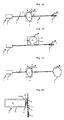
- FIG. 3a a schematic representation of an access and / or start system according to the prior art equipping a vehicle
- FIG. 3b a schematic representation of an access and / or start system according to the invention
- FIG. 4a and 4b a schematic representation of an embodiment of the invention in which two antennas emit alternately.
- the figure 1 a shows an identification device 1 which comprises an antenna control circuit 2, a main antenna 3, here of ferrite type, and electrical connection means for electrically connecting the control circuit 2 to the main antenna 3.
- the electrical connection means consist of a pair 4 of electrical wires which connect the control circuit 2 to the main antenna 3.
- the pair 4 of electrical wires makes it possible to convey the electrical signals of the main antenna 3 transmits electromagnetic signals S corresponding to the useful signals. These signals S are detectable by an identifying device (not shown) in a coverage area.
- the pair 4 of electrical wires may have a length of several meters so that the control circuit 2 can be located at the location of the vehicle where the identification device is present and that the antenna 3 can be located inside. an area to cover.
- the two electrical son are normally joined over their entire length for one hand, facilitate integration into the vehicle, and secondly, limit the magnetic field radiation.
- the two sons are, for example, joined.
- the two electrical wires of this pair 4 are advantageously twisted around each other on parts 5 and 6.
- the detorsed part 7 is made of so that the two son 8 and 9 of the pair 4 generally describe a form of O.
- other forms can be envisaged depending on the coverage area that is desired.
- the detorsed part 7 thus plays the role of a loop-type secondary antenna which emits electromagnetic signals detectable by the identifier around this part 7.
- secondary antenna are detectable by an identifier in a large area around the detorsed part.
- Each stranded portion 7 of particular shape corresponds to a transmission power and an impedance.
- the portion 7 of the son detoursadées 8 and 9 must not delimit a surface A too large so that the impedance formed by the pair 4 of son and the main antenna 3 is not too modified.
- the portion 7 being detoursadée must not change by more than 15% the total impedance of the antenna and the pair of 4 son. This limited modification of the total impedance allows the control circuit 2 to discharge the same current as that delivered when the pair 4 of electrical wires is completely twisted.
- the figure 1b shows an alternative embodiment of Figure la in which the detorsaded portion 7 is no longer formed from the two son 8 and 9 but from only one of the two son of the pair of electrical son 4. More specifically, in this embodiment, only one of the two son of the pair 4 is detorsadé so that the portion 7 delimits a surface.
- the surface A2 may be formed either by the wire 8 or by the wire 9 of the electrical pair 4.
- the two son 8 or 9 of the part 7 is still spaced apart from each other more than they are in the twisted parts 5 and 6.
- FIG. 1a and 1b show a variant of Figures 1a and 1b wherein the main antenna 3 is a loop antenna.
- the invention can be achieved by using connection means connecting any type of antenna to an antenna control circuit 2.
- the same pair of wires is used to make the main antenna 3, the secondary antenna 7, and the electrical connection between the control circuit 2 and the antennas 3 and 7.
- a loop-type secondary antenna is produced locally in series with the main antenna 3.
- This secondary antenna is produced with a zero cost since it is made from wires already present in the original system. which are arranged in a particular way.
- the invention does not require any additional electronic circuits.
- the control circuit 2 of the main antenna 3 allows control and feeding not only of the antenna main but also the secondary antenna 7.
- the signals emitted by the main antenna and the secondary antenna formed by part 7 are the same.
- Secondary antenna parts are here directly made from the pair 4 of electrical wires connecting the control circuit 2 to the main antenna 3, for example by locally detaching one or both of the electrical wires 8 and 9 so as to exclude these same sons of each other.
- these secondary antenna parts may comprise an electric wire, or two spaced apart wires, which are attached and connected on either side, either by welding, or by means of connectors, with two wires or two pairs of wires. electric wires respectively connected to the control circuit and to the main antenna.
- the figures 2 show examples of embodiments of secondary antenna parts 7 which are mounted on supports 14 or 15.
- one of the son of the pair 4 of electrical son is hooked to a support 14 of rectangular shape, so as to define a well-defined surface A3 between two ends of the two torsades 5.1 and 6.1.
- This well-defined surface makes it possible to calibrate the intensity of the magnetic field generated by the detoured portion forming a secondary antenna.
- the support 14 it is thus possible to industrially create parts 7 that have been uncoupled so that the surface formed delimited by these parts 7 is always the same from one vehicle to another and therefore the intensity of the signals transmitted by these secondary antennas are also the same from one vehicle to another.
- the support 14 makes it possible to precisely calibrate the intensity of the secondary antenna formed by a part 7 that is untwisted.
- the portion 7 detorsaded mounted on the support 14 has a U-shaped and is connected in series with one of the two son 8 or 9 of the pair 4 of son son.
- the support 14 is made from a flex-type cable which has been welded to the ends of two son located at the ends of this cable.
- this support 14 is a plastic support having a groove inside which the thread of part 7 is introduced.
- the shapes of part 7 and the support can be any and adapt to the shape of the area to be covered.
- the detorsed part 7 can be connected to the pair of wires 4 thanks to a connector assembly 16 and 17. Indeed, one of the wires of the pair 4 can be cut and connected to a connector 16 and the two ends of the wire of the stripped portion can be connected to a connector 17.
- the stripped portions 7 can be placed beforehand in areas where the electromagnetic signals are not detected by an identifier and connected to the pair 4 of electric wires at the last moment.
- the figure 2b shows a variant of the realization of the figure 2a .
- the two son of the pair 4 are untwisted and mounted on a support 15 so as to delimit a surface A4 which extends on either side of this pair 4, between ends of the two twists 5.1 and 6.1 .
- This configuration amounts to producing two parts 7 that have been untwined and described in the figure 2a .
- the two connectors 16 connect the ends of the twisted parts and the two connectors 17 connect the ends of the part 7 being untwisted.
- a first connector connects four ends of the twisted portions 5 and 6 and a second connector connects four ends of the detorsed portion 7.
- the support 15 may be a flex-type cable or a plastic plate having a groove.
- the figures 3 show the embodiment of the invention inside a passenger compartment 18 of a vehicle.
- the antenna coverage areas are represented in two dimensions but it is actually a volume that these coverage areas actually describe.
- the figure 3a shows an example of the state of the art in which a main antenna 3 for example ferrite type provides coverage of a main zone Z1.
- This main antenna 3 is connected to the control circuit 2 by conventional electrical connection means, namely a pair of electrical wires, preferably twisted over their entire length.
- Zone Z1 covers most of the volume interior of the passenger compartment 18 and extends slightly outside of this cabin 18.
- areas 19 and 20 hatched are not covered by the main antenna 3.
- These areas 19 and 20 here correspond to extreme parts of the passenger compartment 18, for example at the ends of a dashboard and at the ends of a rear shelf.
- the figure 3b shows an example of use of the invention in which the pair of wires connecting the main antenna 3 to the control circuit 2 has been untwisted in two places, so as to create two loops forming two secondary antennas which are electrically connected to each other. series with the main antenna 3 and whose coverage areas are referenced 21-22. Other locations could be provided to cover the rear areas.
- the zones 21-22 covered by these secondary antennas are much smaller than the zone Z1 covered by the main antenna 3 of ferrite type or loop type.
- the coverage areas of the secondary antennas each correspond to 10% of the coverage area of the main antenna.
- Detangling the pair of wires thus makes it possible to produce several antennas from a single main antenna. It is thus possible to achieve several zones 21-22 secondary coverage distinct from the Z1 coverage area of the main antenna to cover the overall volume of the passenger compartment 18 of the vehicle.
- the pair of wires is detorsed locally around a dashboard or inside a box separated from the passenger compartment by a metal wall which absorbs the low frequency electromagnetic signals, about 125 kHz, emitted by the main antenna 3.
- the pairs of wires can be untwisted in all the extreme or peripheral zones of the passenger compartment 18, such as a glove box, a sun visor, a bezel range, a nasturtium or storage compartments doors or trunk.
- the figures 4 show an example of coverage of the passenger compartment 18 of a vehicle with two main antennas 25 and 26, for example ferrite type.
- an area 29 of coverage of the main antenna 25 is hatched while on the figure 4b a zone 30 of coverage of the antenna 26 is hatched.
- the antenna 25 provides coverage of a front portion of the cockpit 18 while the antenna 26 provides coverage of a rear portion of the cockpit 18.
- these two areas 29 and 30 cover these antennas 25 and 26 therefore provide overall coverage of the interior volume of the passenger compartment 18, with a covering in the area 27 of the vehicle.
- the antennas 25 and 26 emit alternately.
- Non-coverage area may for example correspond to an area where there is a DVD player or car radio player with electronic circuits that emit disturbing signals.
- the pair of son connected to the antenna 26 which does not cover the area 28 to create a secondary antenna according to the invention is used here so that there is no overlap between the zone 28 covered by the undressed portion and the zone covered by the main antenna 26.
- detorsaded portions are made at locations, so that the area of coverage of the portion being undone does not overlap with the coverage area of the main antenna.
Abstract
Description
La présente invention concerne un système d'accès et ou démarrage dit mains libres qui équipe des véhicules automobiles. Le domaine de l'invention est donc celui des véhicules automobiles, tels que les voitures ou les camions. La présente invention a pour objet de rendre les signaux électromagnétiques émis par le système mains libres détectables à l'intérieur de tout l'habitacle d'un véhicule. L'invention a aussi pour objet de limiter le coût d'un tel système.The present invention relates to a system of access and or so-called hands-free startup that equips motor vehicles. The field of the invention is that of motor vehicles, such as cars or trucks. The object of the present invention is to make the electromagnetic signals emitted by the hands-free system detectable inside the entire passenger compartment of a vehicle. The invention also aims to limit the cost of such a system.
Les systèmes mains-libres équipent la plupart des véhicules automobiles. En général, ces systèmes mains-libres comportent un dispositif d'identification embarqué au niveau du véhicule, ainsi qu'un identifiant mobile porté par un usager. Le dispositif d'identification émet des signaux électromagnétiques dits d'interrogation à destination de l'identifiant qui sont détectables par ce dernier dans une zone de couverture donnée.Hands-free systems equip most motor vehicles. In general, these hands-free systems include an on-vehicle identification device and a mobile identifier worn by a user. The identification device transmits electromagnetic so-called interrogation signals to the identifier that are detectable by the latter in a given coverage area.
Ainsi, lorsque l'identifiant se situe à l'intérieur de cette zone de couverture, il émet en retour des signaux électromagnétiques dits de réponse à destination du dispositif d'identification afin de lui indiquer sa présence. Selon la zone de couverture considérée (zone extérieure au véhicule, ou zone intérieure) le véhicule peut alors être soit décondamné/condamné, soit démarré. En revanche, lorsque l'identifiant se situe à l'extérieur de la zone de couverture, il ne reçoit pas les signaux d'interrogation, et n'émet donc pas de signaux de réponse à destination du dispositif d'identification. L'identifiant est alors réputé absent.Thus, when the identifier is within this coverage area, it sends back so-called electromagnetic response signals to the identification device to indicate its presence. Depending on the area of coverage considered (exterior area of the vehicle, or interior area) the vehicle can then be either unlocked / condemned or started. On the other hand, when the identifier is outside the coverage area, it does not receive the interrogation signals, and therefore does not transmit response signals to the identification device. The identifier is then deemed absent.
Le dispositif d'identification, pour émettre les signaux électromagnétiques à destination de l'identifiant, comporte au moins une antenne. On appellera ainsi dans la suite du document, zone de couverture d'une antenne, la zone de couverture dans laquelle les signaux émis par cette antenne sont détectables. On pourra aussi dire d'une antenne qu'elle couvre une certaine zone lorsque les signaux qu'elle émet sont détectables à l'intérieur de cette zone.The identification device for transmitting the electromagnetic signals to the identifier comprises at least one antenna. In the following, the coverage area of an antenna will be referred to as the coverage area in which the signals emitted by this antenna are detectable. It can also be said of an antenna that it covers a certain area when the signals it emits are detectable within this zone.
Deux types d'antenne sont principalement connus et utilisés dans le domaine de l'automobile : les antennes de type ferrite et les antennes de type boucle. Les antennes de type ferrite possèdent une structure proche de celle d'une bobine. En effet, une antenne ferrite comporte notamment un fil enroulé autour d'un noyau en fer doux de manière à constituer des spires. Pour une antenne de type ferrite, les signaux émis rayonnent donc autour de l'endroit où se situe l'antenne. L'antenne de type ferrite est donc située à l'intérieur de la zone dans laquelle on souhaite détecter la présence d'un identifiant. Plusieurs antennes de type ferrite peuvent être utilisées afin de couvrir le volume intérieur d'un habitacle d'un véhicule.Two types of antenna are mainly known and used in the automotive field: ferrite type antennas and loop type antennas. The antennas of ferrite type have a structure close to that of a coil. Indeed, a ferrite antenna includes a wire wound around a soft iron core so as to form turns. For a ferrite type antenna, the emitted signals radiate around the location of the antenna. The ferrite type antenna is therefore located inside the zone in which it is desired to detect the presence of an identifier. Several ferrite antennas can be used to cover the interior volume of a passenger compartment of a vehicle.
En ce qui concerne les antennes de type boucle, elles comportent un ou plusieurs fils conducteurs qui décrivent une ou plusieurs boucles. En général, les antennes de type boucle sont placées à l'intérieur du véhicule, de manière à former des zones à l'intérieur desquelles on souhaite détecter la présence de l'identifiant.With regard to the loop type antennas, they comprise one or more conductive wires that describe one or more loops. In general, the loop type antennas are placed inside the vehicle, so as to form areas within which it is desired to detect the presence of the identifier.
D'autres antennes peuvent être utilisées (par exemple des antennes sur support flexible, ou des antennes sérigraphiées sur PCB ...).Other antennas can be used (for example antennas on flexible support, or screen printed antennas on PCB ...).
Chaque antenne est utilisée avec un circuit électronique de contrôle d'antenne qui l'alimente et lui délivre des signaux utiles à transmettre. Une antenne est reliée à son circuit de contrôle par l'intermédiaire de moyens de connexion électriques, constitués généralement d'une paire de fils d'une longueur pouvant atteindre plusieurs mètres pour disposer l'antenne à un endroit donné. Pour limiter le rayonnement de champ électromagnétique le long de ces fils, ces derniers sont avantageusement torsadés.Each antenna is used with an electronic antenna control circuit that feeds it and delivers useful signals to transmit. An antenna is connected to its control circuit via electrical connection means, generally consisting of a pair of wires up to several meters long to arrange the antenna at a given location. To limit the electromagnetic field radiation along these son, the latter are advantageously twisted.
Ces antennes fonctionnent correctement mais ne permettent pas une couverture complète de l'intérieur d'un habitacle.These antennas work properly but do not allow complete coverage of the interior of a cabin.
En effet, les signaux émis par ces antennes ne sont pas toujours détectables à l'intérieur de tout le véhicule. Ainsi, dans les parties extrêmes, telles que les coins du véhicule, les boites de rangement ou certains coins du coffre, les signaux émis par ces antennes peuvent ne pas être détectés par le dispositif identifiant.Indeed, the signals emitted by these antennas are not always detectable inside the entire vehicle. Thus, in the extreme parts, such as the corners of the vehicle, the storage boxes or certain corners of the trunk, the signals emitted by these antennas may not be detected by the identifying device.
En outre, des circuits électroniques situés à l'intérieur du véhicule peuvent engendrer des signaux électromagnétiques qui perturbent les signaux émis par ces antennes. Ces circuits électroniques peuvent donc engendrer des zones où les signaux émis par une antenne ne sont pas détectables par un identifiant. Par exemple, à l'endroit où se situe un tableau de bord qui comporte de nombreux composants électroniques, les signaux électromagnétiques émis par les antennes sont très difficilement (ou ne sont pas) détectables par l'identifiant.In addition, electronic circuits located inside the vehicle can generate electromagnetic signals that disturb the signals emitted by these antennas. These electronic circuits can therefore generate zones where the signals emitted by an antenna are not detectable by an identifier. For example, where there is a dashboard which has many electronic components, the electromagnetic signals emitted by the antennas are very difficult (or not) detectable by the identifier.
Toutes ces zones de non couverture dues à une géométrie du véhicule ou à des signaux perturbateurs, peuvent poser des problèmes à un usager. En effet, si ce dernier entre dans une voiture et qu'il dépose son identifiant dans une zone de non couverture par une antenne, il ne sera pas autorisé à démarrer le véhicule alors qu'il se trouve à l'intérieur de ce véhicule.All of these non-coverage areas due to vehicle geometry or interfering signals can cause problems for a user. Indeed, if the latter enters a car and it deposits its identifier in a non-coverage area by an antenna, it will not be allowed to start the vehicle while it is inside the vehicle.
Pour remédier à ces problèmes de non couverture et de signaux perturbateurs, on pourrait envisager une utilisation d'antennes de forte puissance qui pourraient couvrir tout l'intérieur de l'habitacle du véhicule d'une manière sûre. Toutefois, une antenne dont la zone de couverture serait supérieure dépasserait largement les contours de l'habitacle du véhicule, ce qui pourrait engendrer d'autres problèmes. Notamment, un utilisateur portant un identifiant et situé à l'extérieur du véhicule pourrait être autorisé à démarrer le véhicule alors qu'il ne se trouverait pas à l'intérieur de l'habitacle.To remedy these problems of non-coverage and disturbing signals, one could consider the use of high power antennas that could cover the entire interior of the passenger compartment of a vehicle in a safe manner. However, an antenna with a higher coverage area would greatly exceed the contours of the vehicle cabin, which could lead to other problems. In particular, a user with an identifier and located outside the vehicle could be allowed to start the vehicle while it is not inside the cabin.
On pourrait également placer des antennes supplémentaires aux endroits où les signaux électromagnétiques ne sont pas détectables par l'identifiant. Toutefois, ces antennes supplémentaires nécessiteraient des circuits électroniques supplémentaires avec notamment des ajouts de circuits de contrôle d'antenne afin de commander les différentes antennes. Ces antennes supplémentaires reviendraient donc cher et leur circuit de contrôle engendrerait un encombrement supplémentaire du dispositif d'identification.Additional antennas could also be placed where the electromagnetic signals are not detectable by the identifier. However, these additional antennas require additional electronic circuits including additions of antenna control circuits to control the different antennas. These additional antennas would be expensive and their control circuit would cause additional congestion of the identification device.
L'invention se propose de résoudre ces problèmes de non couverture de l'intérieur de l'habitacle du véhicule en n'augmentant pas le coût du dispositif d'identification d'origine et en n'introduisant par ailleurs aucun circuit électronique supplémentaire.The invention proposes to solve these problems of non-coverage of the interior of the passenger compartment of the vehicle by not increasing the cost of the original identification device and by not introducing any additional electronic circuit.
A cet effet, dans l'invention, on réalise, avec les fils électriques faisant partie des moyens de connexion électriques reliant un circuit de contrôle à une antenne principale, une ou plusieurs boucles qui engendrent un champ magnétique local. On crée ainsi localement des antennes secondaires qui sont connectées en série avec l'antenne principale.For this purpose, in the invention, with the electric wires forming part of the electrical connection means connecting a control circuit to a main antenna, one or more loops are produced which generate a local magnetic field. Local antennas are thus created locally which are connected in series with the main antenna.
Conformément à l'invention, les boucles peuvent être obtenues avec un fil électrique, ou encore deux fils électriques qui peuvent être écartés à plusieurs endroits différents. En écartant les fils électriques aux endroits correspondant aux zones de non couverture précitées, il est ainsi possible de rendre détectables ces signaux à tous les endroits de l'intérieur de l'habitacle du véhicule.According to the invention, the loops can be obtained with an electric wire, or two electrical son that can be separated in several different places. By discarding the electrical wires at the locations corresponding to the above non-coverage areas, it is thus possible to make these signals detectable at all locations inside the passenger compartment of the vehicle.
L'écartement des fils modifie très légèrement l'impédance totale de l'antenne et des fils électriques qui lui sont reliés. Ainsi, il n'est pas nécessaire de modifier le circuit de contrôle de l'antenne. En outre, le coût de l'invention est quasiment nul car elle est réalisée à partir de fils électriques très peu onéreux, voire déjà présents dans le dispositif d'identification d'origine. En effet, dans l'invention, seule la disposition des fils reliant l'antenne principale à son circuit de contrôle est modifiée.The spacing of the wires very slightly modifies the total impedance of the antenna and the electric wires connected thereto. Thus, it is not necessary to modify the control circuit of the antenna. In addition, the cost of the invention is virtually zero because it is made from electrical son very inexpensive, or already present in the original identification device. Indeed, in the invention, only the arrangement of the son connecting the main antenna to its control circuit is changed.
La présente invention concerne donc un dispositif d'identification pour véhicule automobile équipé d'un système d'accès et/ou démarrage dit mains-libres, le dispositif comportant une antenne principale, un circuit électronique de contrôle d'antenne et des moyens de connexion électrique reliant ce circuit électronique à cette antenne principale, caractérisé en ce que les moyens de connexion électrique comportent au moins un fil électrique agencé de manière à former sur au moins une partie une boucle qui engendre un champ magnétique local, formant ainsi une antenne secondaire.The present invention therefore relates to an identification device for a motor vehicle equipped with a system of access and / or start said hands-free, the device comprising a main antenna, an electronic circuit antenna control and connection means electrical connection connecting this electronic circuit to this main antenna, characterized in that the electrical connection means comprise at least one electrical wire arranged to form on at least a part a loop which generates a local magnetic field, thus forming a secondary antenna.
La présente invention sera mieux comprise à la lecture de la description qui suit et à la vue des figures qui l'accompagnent. Ces figures sont données à titre illustratif mais nullement limitatif de l'invention. Ces figures montrent :The present invention will be better understood on reading the description which follows and on seeing the figures which accompany it. These figures are given for illustrative purposes but in no way limitative of the invention. These figures show:
-
-
-
-
-
Les éléments communs aux figures conservent la même référence d'une figure à l'autre.The elements common to the figures retain the same reference from one figure to another.
La
La paire 4 de fils électriques peut posséder une longueur de plusieurs mètres afin que le circuit 2 de contrôle puisse se situer à l'endroit du véhicule où le dispositif d'identification est présent et que l'antenne 3 puisse se situer à l'intérieur d'une zone à couvrir.The
Classiquement, les deux fils électriques sont normalement réunis sur toute leur longueur pour d'une part, faciliter l'intégration dans le véhicule, et d'autre part, limiter le rayonnement de champ magnétique. Les deux fils sont par exemple jointifs. Afin de limiter encore plus le rayonnement électromagnétique, et comme représenté à titre d'exemple non limitatif sur les
En revanche, conformément à l'invention, il existe au moins une partie 7 dans laquelle les fils électriques de la paire 4 ne sont pas réunis, mais au contraire écartés l'un de l'autre. Dans l'exemple représenté sur la
La partie 7 détorsadée joue ainsi le rôle d'une antenne secondaire de type boucle qui émet des signaux électromagnétiques détectables par l'identifiant autour de cette partie 7. Plus la surface A1 de cette antenne secondaire est grande, plus les signaux électromagnétiques émis par cette antenne secondaire sont détectables par un identifiant dans une grande zone autour de la partie détorsadée. Plus cette surface A1 est petite, plus les signaux émis par cette antenne secondaire sont détectables dans une petite zone autour de la partie détorsadée.The
A chaque partie 7 détorsadée de forme particulière correspond une puissance d'émission et une impédance. La partie 7 détorsadée des fils 8 et 9 ne doit donc pas délimiter une surface A trop grande afin que l'impédance formée par la paire 4 de fils et l'antenne principale 3 ne soit pas trop modifiée. Dans un exemple, la partie 7 détorsadée ne doit pas modifier de plus de 15% l'impédance totale de l'antenne et de la paire 4 de fils. Cette modification limitée de l'impédance totale permet au circuit 2 de contrôle de débiter le même courant que celui débité lorsque la paire 4 de fils électriques est complètement torsadée.Each stranded
La
La figure le montre une variante des
Avec l'invention, on réalise donc localement une antenne secondaire de type boucle en série avec l'antenne principale 3. Cette antenne secondaire est réalisée avec un coût nul puisqu'elle est réalisée à partir de fils déjà présents dans le système d'origine qui sont agencés de manière particulière. Par ailleurs, l'invention ne nécessite aucun ajout de circuits électroniques supplémentaires. En effet, le circuit 2 de commande de l'antenne principale 3 permet le contrôle et l'alimentation non seulement de l'antenne principale mais aussi de l'antenne secondaire 7. On remarquera d'ailleurs que les signaux émis par l'antenne principale et l'antenne secondaire formée par partie 7 sont les mêmes.With the invention, therefore, a loop-type secondary antenna is produced locally in series with the
Dans les réalisations des
Des parties formant antennes secondaires sont ici directement réalisées à partir de la paire 4 de fils électriques reliant le circuit 2 de contrôle à l'antenne principale 3, par exemple en détorsadant localement un ou les deux fils électriques 8 et 9 de manière à écarter ces mêmes fils l'un de l'autre. En variante, ces parties formant antennes secondaires peuvent comporter un fil électrique, ou deux fils écartés, qui sont rapportés et reliés de part et d'autre, soit par soudage, soit par l'intermédiaire de connecteurs, à deux fils ou deux paires de fils électriques reliés respectivement au circuit de contrôle et à l'antenne principale. On peut notamment envisager, au montage d'un tel dispositif sur le véhicule, d'utiliser une paire de fils torsadés reliant le circuit de contrôle 2 à l'antenne principale 3, couper un ou deux fils aux endroits où l'on souhaite placer des antennes secondaires, et connecter ces antennes secondaires aux endroits où les fils ont été coupés.Secondary antenna parts are here directly made from the
Les
Ainsi, sur la
Sur la
En outre, la partie 7 détorsadée peut être reliée à la paire 4 de fils à la faveur d'un assemblage de connecteurs 16 et 17. En effet, un des fils de la paire 4 peut être coupé et relié à un connecteur 16 et les deux extrémités du fil de la partie détorsadée peuvent être reliées à un connecteur 17. Ainsi, dans une réalisation industrielle, les parties 7 détorsadées peuvent être placées au préalable dans des zones où les signaux électromagnétiques ne sont pas détectés par un identifiant et reliées à la paire 4 de fils électriques au dernier moment.In addition, the
Bien entendu, il est possible d'utiliser des connecteurs afin de réaliser la partie 7 détorsadée rapportée sans forcément utiliser un support 14.Of course, it is possible to use connectors in order to produce the reported
La
Afin de réaliser la connexion entre la partie 7 détorsadée et les parties 5 et 6 torsadées, il est donc possible d'utiliser deux connecteurs 16 et deux connecteurs 17. Les deux connecteurs 16 relient les extrémités des parties torsadées et les deux connecteurs 17 relient les extrémités de la partie 7 détorsadée. En variante, on utilise uniquement deux connecteurs pour réaliser ce montage. Un premier connecteur relie quatre extrémités des parties 5 et 6 torsadées et un deuxième connecteur relie quatre extrémités de la partie 7 détorsadée.In order to make the connection between the
Comme précité, le support 15 peut être un câble de type flex ou une plaque en plastique comportant une rainure.As mentioned above, the
Le choix du mode de réalisation dépend de la forme et de l'emplacement des zones que les parties détorsadées doivent couvrir. Si ces zones à couvrir se déploient de part et d'autre de la paire 4 de fils, on utilisera de préférence le support 15. En revanche, si elles se déploient seulement d'un côté de cette paire de fils 4, on utilisera plutôt le support 14.The choice of embodiment depends on the shape and location of the areas that the untouched portions must cover. If these zones to be covered unfold on both sides of the
Les
La
La
Les zones 21-22 couvertes par ces antennes secondaires sont beaucoup plus petites que la zone Z1 couverte par l'antenne 3 principale de type ferrite ou de type boucle. Dans un exemple, les zones de couverture des antennes secondaires correspondent chacune à 10% de la zone de couverture de l'antenne principale.The zones 21-22 covered by these secondary antennas are much smaller than the zone Z1 covered by the
Détorsader la paire de fils permet ainsi de réaliser plusieurs antennes à partir d'une seule antenne principale. Il est ainsi possible de réaliser plusieurs zones 21-22 de couverture secondaires distinctes de la zone Z1 de couverture de l'antenne principale afin de couvrir le volume global de l'habitacle 18 du véhicule.Detangling the pair of wires thus makes it possible to produce several antennas from a single main antenna. It is thus possible to achieve several zones 21-22 secondary coverage distinct from the Z1 coverage area of the main antenna to cover the overall volume of the
En variante, on détorsade la paire de fils localement autour d'un tableau de bord ou à l'intérieur d'un coffre séparé de l'habitacle par une paroi métallique qui absorbe les signaux électromagnétiques de basses fréquences, environ 125kHz, émis par l'antenne principale 3. En outre, les paires de fils peuvent être détorsadés dans toutes les zones extrêmes ou périphériques de l'habitacle 18, telles qu'une boite à gant, un pare-soleil, un range lunette, une capucine ou des rangements de portières ou de coffre.As a variant, the pair of wires is detorsed locally around a dashboard or inside a box separated from the passenger compartment by a metal wall which absorbs the low frequency electromagnetic signals, about 125 kHz, emitted by the
Les
Sur la
Dans une réalisation particulière, pour éviter la zone 27 de recouvrement qui pourrait nuire à la réception des signaux par un identifiant, les antennes 25 et 26 émettent de manière alternée.In a particular embodiment, to avoid the
Par ailleurs, sur la
Pour éviter là encore un recouvrement, on utilise de préférence la paire de fils reliée à l'antenne 26 qui ne couvre pas la zone 28 afin de créer une antenne secondaire selon l'invention. Plus précisément, on utilise ici la paire de fils électriques reliant l'antenne 26 à son circuit de contrôle afin qu'il ne se produise pas de recouvrement entre la zone 28 couverte par la partie détorsadée et la zone couverte par l'antenne principale 26. Plus généralement, selon l'invention, on réalise des parties détorsadées à des endroits, de manière à ce que la zone de couverture de la partie détorsadée ne se recouvre pas avec la zone de couverture de l'antenne principale.To avoid again overlapping, it is preferably used the pair of son connected to the
En conséquence, lorsque sur la
Claims (10)
- Identification device (1) for an automobile vehicle equipped with a so-called hands-free access and/or starting system, the device comprising a main antenna (3), an electronic antenna control circuit (2) and electrical connection means (4, 8, 9) connecting this electronic circuit (2) to this main antenna (3), characterised in that the electrical connection means (4, 8, 9) comprise at least one electrical wire (8, 9) arranged so as to form on at least one part (7), a loop that generates a local magnetic field thus forming a secondary antenna.
- Device according to claim 1, characterised in that the electrical connection means comprise two electrical wires (8, 9) that are separated from each other at said part (7).
- Device according to claim 2, characterised in that the electrical connection means (4, 8, 9) are composed of only two electrical wires (8, 9), these two electrical wires being connected outside said part so as to form a pair (4) of wires with low electromagnetic radiation.
- Device according to claim 3, characterised in that the two electrical wires (8, 9) are twisted around each other outside said part (7).
- Device according to any one of claims 2 to 4, characterised in that the two electrical wires are also used to form the main antenna (3).
- Device according to claim 1, characterised in that said part (7) is made by welding or by means of connectors (16, 17) connecting said electrical wire at each side to two electrical wires, one of which is connected to the control circuit (2) and the other to the main antenna (3).
- Device according to one of claims 1 to 6, characterised in that said electrical wire at said part (7) is mounted on a support (14, 15).
- Device according to one of the previous claims, characterised in that- the main antenna emits electromagnetic signals (S) that can be detected by an identifier in a first coverage zone (Z1),- said part forming a secondary antenna emits electromagnetic signals that can be detected by the identifier in a second coverage zone (21-22) smaller than the first coverage zone.
- Device according to claim 8, characterised in that the second coverage zone globally corresponds to 10% of the first coverage zone.
- Identification device according to one of the claims 8 or 9, characterised in that said part forming the secondary antenna is made at a location such that the second coverage zone and the first coverage zone do not overlap.
Applications Claiming Priority (2)
| Application Number | Priority Date | Filing Date | Title |
|---|---|---|---|
| FR0403970A FR2869006B1 (en) | 2004-04-16 | 2004-04-16 | IDENTIFICATION DEVICE FOR A MOTOR VEHICLE EQUIPPED WITH A HANDS-FREE ACCESS AND / OR STARTING SYSTEM |
| PCT/EP2005/051609 WO2005110824A1 (en) | 2004-04-16 | 2005-04-12 | Identification device for a motor vehicle comprising a hands-free access and/or engine start system |
Publications (2)
| Publication Number | Publication Date |
|---|---|
| EP1740420A1 EP1740420A1 (en) | 2007-01-10 |
| EP1740420B1 true EP1740420B1 (en) | 2009-02-18 |
Family
ID=34945741
Family Applications (1)
| Application Number | Title | Priority Date | Filing Date |
|---|---|---|---|
| EP05729522A Not-in-force EP1740420B1 (en) | 2004-04-16 | 2005-04-12 | Identification device for a motor vehicle comprising a hands-free access and/or engine start system |
Country Status (5)
| Country | Link |
|---|---|
| EP (1) | EP1740420B1 (en) |
| AT (1) | ATE423045T1 (en) |
| DE (1) | DE602005012816D1 (en) |
| FR (1) | FR2869006B1 (en) |
| WO (1) | WO2005110824A1 (en) |
Families Citing this family (1)
| Publication number | Priority date | Publication date | Assignee | Title |
|---|---|---|---|---|
| DE102012212418A1 (en) * | 2012-07-16 | 2014-01-30 | Brose Fahrzeugteile Gmbh & Co. Kg, Hallstadt | Sensor device for a vehicle |
Family Cites Families (3)
| Publication number | Priority date | Publication date | Assignee | Title |
|---|---|---|---|---|
| US5883599A (en) * | 1997-01-16 | 1999-03-16 | Ford Motor Company | Antenna system for a motor vehicle |
| FR2794086B1 (en) * | 1999-05-27 | 2001-08-24 | Valeo Securite Habitacle | VEHICLE LOCK CONTROL DEVICE |
| FR2810946B3 (en) * | 2000-07-03 | 2002-04-19 | Valeo Electronique | MOTOR VEHICLE EQUIPPED WITH AN IMPROVED "HANDS-FREE" ACCESS SYSTEM FOR LOCATING A PORTABLE BADGE |
-
2004
- 2004-04-16 FR FR0403970A patent/FR2869006B1/en not_active Expired - Lifetime
-
2005
- 2005-04-12 WO PCT/EP2005/051609 patent/WO2005110824A1/en not_active Application Discontinuation
- 2005-04-12 AT AT05729522T patent/ATE423045T1/en not_active IP Right Cessation
- 2005-04-12 DE DE602005012816T patent/DE602005012816D1/en active Active
- 2005-04-12 EP EP05729522A patent/EP1740420B1/en not_active Not-in-force
Also Published As
| Publication number | Publication date |
|---|---|
| DE602005012816D1 (en) | 2009-04-02 |
| FR2869006A1 (en) | 2005-10-21 |
| ATE423045T1 (en) | 2009-03-15 |
| FR2869006B1 (en) | 2006-07-14 |
| EP1740420A1 (en) | 2007-01-10 |
| WO2005110824A1 (en) | 2005-11-24 |
Similar Documents
| Publication | Publication Date | Title |
|---|---|---|
| WO2020038881A1 (en) | Device for detecting an item of electronic equipment and for communicating with two near-field communication antennae | |
| FR2607984A1 (en) | SYSTEM FOR CONTROLLING MOTORIZED ICE REGULATORS OF A VEHICLE | |
| EP1740420B1 (en) | Identification device for a motor vehicle comprising a hands-free access and/or engine start system | |
| FR2833292A1 (en) | SYSTEM FOR DETECTING THE PRESENCE OF A USER, PARTICULARLY FOR A MOTOR VEHICLE | |
| FR2755925A1 (en) | Combined door lock and remote control for motor vehicle | |
| FR3006775A1 (en) | SYSTEM FOR PROJECTING LUMINOUS INDICATIONS | |
| EP1363354B1 (en) | Vehicle equipped with a device for transmitting signals | |
| EP1132999B1 (en) | Motor vehicle provided with an antenna for a dedicated communication system | |
| EP3365940B1 (en) | Touch-screen display device with reduced interfering electromagnetic radiation emission | |
| EP2747039B1 (en) | Motor vehicle remote control comprising a magnetic coupling cancellation device | |
| WO2019238696A1 (en) | Device for high-frequency near-field communication and for recharging a portable electronic apparatus by induction | |
| BE1007985A5 (en) | Installation of remote control, especially for the opening and / or closing doors, garage or motor vehicles. | |
| FR2808125A1 (en) | Car low frequency hands free locking/unlocking antenna having loop antenna winding car roof placed and extending rear windscreen/boot and front windscreen | |
| EP3729924B1 (en) | High-voltage charger on board a hybrid or electric motor vehicle incorporating a capacitive filtering device | |
| FR2689688A1 (en) | Dual purpose radio aerial for use in vehicle - has inner wire core projecting beyond shorter cylindrical casing with separate connections to two radio circuits | |
| WO2018178062A1 (en) | Underwater craft equipped with a winch for deploying a wired antenna | |
| FR2866156A1 (en) | FM2 screened antenna for station wagon type motor vehicle, has aerial, on back window, with defroster network having vertical symmetrical lines, and screened in F form of servitude antenna connected by bifilar cable to electronic case | |
| KR102410861B1 (en) | Glass wiring apparatus and vehicle having the same | |
| EP3560043A1 (en) | Electrical assembly for a motor vehicle comprising a coaxial cable and an electrical terminal | |
| FR2936753A1 (en) | Rear vision system for motor vehicle, has imaging units formed by another imaging unit i.e. camera, integrated in mobile telephone that is placed in support in detachable manner, where support is provided in cab interior of vehicle | |
| FR3062241A1 (en) | ANTENNA FOR HANDS-FREE ACCESS AND / OR STARTING SYSTEM FOR MOTOR VEHICLE | |
| FR2852170A1 (en) | TRANSMISSION AND / OR RECEPTION DEVICE AND SECURITY SYSTEM INCLUDING SUCH A DEVICE | |
| FR2992505A1 (en) | Communication device for use in e.g. communicating system in motor vehicle, has connection unit transferring first and second signals between black box and antenna, where part of unit induces collection of third signals with cable | |
| FR2797233A1 (en) | DEVICE FOR TRANSMITTING SIGNALS BETWEEN A MONITORING AND CONTROL UNIT OF A MOTOR VEHICLE AND EQUIPMENT MOUNTED ON A SUB-ASSEMBLY THEREOF | |
| EP0305265A1 (en) | Electrical-information transmission apparatus |
Legal Events
| Date | Code | Title | Description |
|---|---|---|---|
| PUAI | Public reference made under article 153(3) epc to a published international application that has entered the european phase |
Free format text: ORIGINAL CODE: 0009012 |
|
| 17P | Request for examination filed |
Effective date: 20061116 |
|
| AK | Designated contracting states |
Kind code of ref document: A1 Designated state(s): AT BE BG CH CY CZ DE DK EE ES FI FR GB GR HU IE IS IT LI LT LU MC NL PL PT RO SE SI SK TR |
|
| DAX | Request for extension of the european patent (deleted) | ||
| GRAP | Despatch of communication of intention to grant a patent |
Free format text: ORIGINAL CODE: EPIDOSNIGR1 |
|
| GRAS | Grant fee paid |
Free format text: ORIGINAL CODE: EPIDOSNIGR3 |
|
| GRAA | (expected) grant |
Free format text: ORIGINAL CODE: 0009210 |
|
| AK | Designated contracting states |
Kind code of ref document: B1 Designated state(s): AT BE BG CH CY CZ DE DK EE ES FI FR GB GR HU IE IS IT LI LT LU MC NL PL PT RO SE SI SK TR |
|
| REG | Reference to a national code |
Ref country code: GB Ref legal event code: FG4D Free format text: NOT ENGLISH |
|
| REG | Reference to a national code |
Ref country code: CH Ref legal event code: EP |
|
| REG | Reference to a national code |
Ref country code: IE Ref legal event code: FG4D Free format text: LANGUAGE OF EP DOCUMENT: FRENCH |
|
| REF | Corresponds to: |
Ref document number: 602005012816 Country of ref document: DE Date of ref document: 20090402 Kind code of ref document: P |
|
| PG25 | Lapsed in a contracting state [announced via postgrant information from national office to epo] |
Ref country code: ES Free format text: LAPSE BECAUSE OF FAILURE TO SUBMIT A TRANSLATION OF THE DESCRIPTION OR TO PAY THE FEE WITHIN THE PRESCRIBED TIME-LIMIT Effective date: 20090529 Ref country code: FI Free format text: LAPSE BECAUSE OF FAILURE TO SUBMIT A TRANSLATION OF THE DESCRIPTION OR TO PAY THE FEE WITHIN THE PRESCRIBED TIME-LIMIT Effective date: 20090218 Ref country code: NL Free format text: LAPSE BECAUSE OF FAILURE TO SUBMIT A TRANSLATION OF THE DESCRIPTION OR TO PAY THE FEE WITHIN THE PRESCRIBED TIME-LIMIT Effective date: 20090218 Ref country code: SI Free format text: LAPSE BECAUSE OF FAILURE TO SUBMIT A TRANSLATION OF THE DESCRIPTION OR TO PAY THE FEE WITHIN THE PRESCRIBED TIME-LIMIT Effective date: 20090218 Ref country code: LT Free format text: LAPSE BECAUSE OF FAILURE TO SUBMIT A TRANSLATION OF THE DESCRIPTION OR TO PAY THE FEE WITHIN THE PRESCRIBED TIME-LIMIT Effective date: 20090218 |
|
| NLV1 | Nl: lapsed or annulled due to failure to fulfill the requirements of art. 29p and 29m of the patents act | ||
| PG25 | Lapsed in a contracting state [announced via postgrant information from national office to epo] |
Ref country code: SE Free format text: LAPSE BECAUSE OF FAILURE TO SUBMIT A TRANSLATION OF THE DESCRIPTION OR TO PAY THE FEE WITHIN THE PRESCRIBED TIME-LIMIT Effective date: 20090518 Ref country code: PL Free format text: LAPSE BECAUSE OF FAILURE TO SUBMIT A TRANSLATION OF THE DESCRIPTION OR TO PAY THE FEE WITHIN THE PRESCRIBED TIME-LIMIT Effective date: 20090218 Ref country code: IS Free format text: LAPSE BECAUSE OF FAILURE TO SUBMIT A TRANSLATION OF THE DESCRIPTION OR TO PAY THE FEE WITHIN THE PRESCRIBED TIME-LIMIT Effective date: 20090618 Ref country code: AT Free format text: LAPSE BECAUSE OF FAILURE TO SUBMIT A TRANSLATION OF THE DESCRIPTION OR TO PAY THE FEE WITHIN THE PRESCRIBED TIME-LIMIT Effective date: 20090218 |
|
| REG | Reference to a national code |
Ref country code: IE Ref legal event code: FD4D |
|
| PG25 | Lapsed in a contracting state [announced via postgrant information from national office to epo] |
Ref country code: IE Free format text: LAPSE BECAUSE OF FAILURE TO SUBMIT A TRANSLATION OF THE DESCRIPTION OR TO PAY THE FEE WITHIN THE PRESCRIBED TIME-LIMIT Effective date: 20090218 Ref country code: EE Free format text: LAPSE BECAUSE OF FAILURE TO SUBMIT A TRANSLATION OF THE DESCRIPTION OR TO PAY THE FEE WITHIN THE PRESCRIBED TIME-LIMIT Effective date: 20090218 Ref country code: CZ Free format text: LAPSE BECAUSE OF FAILURE TO SUBMIT A TRANSLATION OF THE DESCRIPTION OR TO PAY THE FEE WITHIN THE PRESCRIBED TIME-LIMIT Effective date: 20090218 Ref country code: PT Free format text: LAPSE BECAUSE OF FAILURE TO SUBMIT A TRANSLATION OF THE DESCRIPTION OR TO PAY THE FEE WITHIN THE PRESCRIBED TIME-LIMIT Effective date: 20090727 Ref country code: DK Free format text: LAPSE BECAUSE OF FAILURE TO SUBMIT A TRANSLATION OF THE DESCRIPTION OR TO PAY THE FEE WITHIN THE PRESCRIBED TIME-LIMIT Effective date: 20090218 |
|
| BERE | Be: lapsed |
Owner name: VALEO SECURITE HABITACLE S.A.S. Effective date: 20090430 |
|
| PG25 | Lapsed in a contracting state [announced via postgrant information from national office to epo] |
Ref country code: SK Free format text: LAPSE BECAUSE OF FAILURE TO SUBMIT A TRANSLATION OF THE DESCRIPTION OR TO PAY THE FEE WITHIN THE PRESCRIBED TIME-LIMIT Effective date: 20090218 Ref country code: RO Free format text: LAPSE BECAUSE OF FAILURE TO SUBMIT A TRANSLATION OF THE DESCRIPTION OR TO PAY THE FEE WITHIN THE PRESCRIBED TIME-LIMIT Effective date: 20090218 |
|
| PGFP | Annual fee paid to national office [announced via postgrant information from national office to epo] |
Ref country code: GB Payment date: 20090407 Year of fee payment: 5 |
|
| REG | Reference to a national code |
Ref country code: CH Ref legal event code: PL |
|
| PLBE | No opposition filed within time limit |
Free format text: ORIGINAL CODE: 0009261 |
|
| STAA | Information on the status of an ep patent application or granted ep patent |
Free format text: STATUS: NO OPPOSITION FILED WITHIN TIME LIMIT |
|
| 26N | No opposition filed |
Effective date: 20091119 |
|
| PG25 | Lapsed in a contracting state [announced via postgrant information from national office to epo] |
Ref country code: LI Free format text: LAPSE BECAUSE OF NON-PAYMENT OF DUE FEES Effective date: 20090430 Ref country code: BG Free format text: LAPSE BECAUSE OF FAILURE TO SUBMIT A TRANSLATION OF THE DESCRIPTION OR TO PAY THE FEE WITHIN THE PRESCRIBED TIME-LIMIT Effective date: 20090518 Ref country code: CH Free format text: LAPSE BECAUSE OF NON-PAYMENT OF DUE FEES Effective date: 20090430 |
|
| PG25 | Lapsed in a contracting state [announced via postgrant information from national office to epo] |
Ref country code: MC Free format text: LAPSE BECAUSE OF NON-PAYMENT OF DUE FEES Effective date: 20090430 |
|
| PG25 | Lapsed in a contracting state [announced via postgrant information from national office to epo] |
Ref country code: BE Free format text: LAPSE BECAUSE OF NON-PAYMENT OF DUE FEES Effective date: 20090430 |
|
| PG25 | Lapsed in a contracting state [announced via postgrant information from national office to epo] |
Ref country code: GR Free format text: LAPSE BECAUSE OF FAILURE TO SUBMIT A TRANSLATION OF THE DESCRIPTION OR TO PAY THE FEE WITHIN THE PRESCRIBED TIME-LIMIT Effective date: 20090519 |
|
| GBPC | Gb: european patent ceased through non-payment of renewal fee |
Effective date: 20100412 |
|
| PG25 | Lapsed in a contracting state [announced via postgrant information from national office to epo] |
Ref country code: GB Free format text: LAPSE BECAUSE OF NON-PAYMENT OF DUE FEES Effective date: 20100412 Ref country code: IT Free format text: LAPSE BECAUSE OF FAILURE TO SUBMIT A TRANSLATION OF THE DESCRIPTION OR TO PAY THE FEE WITHIN THE PRESCRIBED TIME-LIMIT Effective date: 20090218 |
|
| PG25 | Lapsed in a contracting state [announced via postgrant information from national office to epo] |
Ref country code: LU Free format text: LAPSE BECAUSE OF NON-PAYMENT OF DUE FEES Effective date: 20090412 |
|
| PG25 | Lapsed in a contracting state [announced via postgrant information from national office to epo] |
Ref country code: HU Free format text: LAPSE BECAUSE OF FAILURE TO SUBMIT A TRANSLATION OF THE DESCRIPTION OR TO PAY THE FEE WITHIN THE PRESCRIBED TIME-LIMIT Effective date: 20090819 |
|
| PG25 | Lapsed in a contracting state [announced via postgrant information from national office to epo] |
Ref country code: TR Free format text: LAPSE BECAUSE OF FAILURE TO SUBMIT A TRANSLATION OF THE DESCRIPTION OR TO PAY THE FEE WITHIN THE PRESCRIBED TIME-LIMIT Effective date: 20090218 |
|
| PG25 | Lapsed in a contracting state [announced via postgrant information from national office to epo] |
Ref country code: CY Free format text: LAPSE BECAUSE OF FAILURE TO SUBMIT A TRANSLATION OF THE DESCRIPTION OR TO PAY THE FEE WITHIN THE PRESCRIBED TIME-LIMIT Effective date: 20090218 |
|
| REG | Reference to a national code |
Ref country code: FR Ref legal event code: PLFP Year of fee payment: 12 |
|
| REG | Reference to a national code |
Ref country code: FR Ref legal event code: PLFP Year of fee payment: 13 |
|
| PGFP | Annual fee paid to national office [announced via postgrant information from national office to epo] |
Ref country code: DE Payment date: 20170412 Year of fee payment: 13 Ref country code: FR Payment date: 20170428 Year of fee payment: 13 |
|
| REG | Reference to a national code |
Ref country code: DE Ref legal event code: R119 Ref document number: 602005012816 Country of ref document: DE |
|
| PG25 | Lapsed in a contracting state [announced via postgrant information from national office to epo] |
Ref country code: DE Free format text: LAPSE BECAUSE OF NON-PAYMENT OF DUE FEES Effective date: 20181101 |
|
| PG25 | Lapsed in a contracting state [announced via postgrant information from national office to epo] |
Ref country code: FR Free format text: LAPSE BECAUSE OF NON-PAYMENT OF DUE FEES Effective date: 20180430 |