EP1740339B1 - Applikation von haftmittel zur herstellung einer hochtemperaturfesten struktur - Google Patents
Applikation von haftmittel zur herstellung einer hochtemperaturfesten struktur Download PDFInfo
- Publication number
- EP1740339B1 EP1740339B1 EP05735078.7A EP05735078A EP1740339B1 EP 1740339 B1 EP1740339 B1 EP 1740339B1 EP 05735078 A EP05735078 A EP 05735078A EP 1740339 B1 EP1740339 B1 EP 1740339B1
- Authority
- EP
- European Patent Office
- Prior art keywords
- foil
- adhesive
- solder
- layer
- corrugated
- Prior art date
- Legal status (The legal status is an assumption and is not a legal conclusion. Google has not performed a legal analysis and makes no representation as to the accuracy of the status listed.)
- Expired - Lifetime
Links
Images
Classifications
-
- F—MECHANICAL ENGINEERING; LIGHTING; HEATING; WEAPONS; BLASTING
- F01—MACHINES OR ENGINES IN GENERAL; ENGINE PLANTS IN GENERAL; STEAM ENGINES
- F01N—GAS-FLOW SILENCERS OR EXHAUST APPARATUS FOR MACHINES OR ENGINES IN GENERAL; GAS-FLOW SILENCERS OR EXHAUST APPARATUS FOR INTERNAL-COMBUSTION ENGINES
- F01N3/00—Exhaust or silencing apparatus having means for purifying, rendering innocuous, or otherwise treating exhaust
- F01N3/02—Exhaust or silencing apparatus having means for purifying, rendering innocuous, or otherwise treating exhaust for cooling, or for removing solid constituents of, exhaust
- F01N3/021—Exhaust or silencing apparatus having means for purifying, rendering innocuous, or otherwise treating exhaust for cooling, or for removing solid constituents of, exhaust by means of filters
- F01N3/022—Exhaust or silencing apparatus having means for purifying, rendering innocuous, or otherwise treating exhaust for cooling, or for removing solid constituents of, exhaust by means of filters characterised by specially adapted filtering structure, e.g. honeycomb, mesh or fibrous
-
- B—PERFORMING OPERATIONS; TRANSPORTING
- B23—MACHINE TOOLS; METAL-WORKING NOT OTHERWISE PROVIDED FOR
- B23K—SOLDERING OR UNSOLDERING; WELDING; CLADDING OR PLATING BY SOLDERING OR WELDING; CUTTING BY APPLYING HEAT LOCALLY, e.g. FLAME CUTTING; WORKING BY LASER BEAM
- B23K1/00—Soldering, e.g. brazing, or unsoldering
- B23K1/20—Preliminary treatment of work or areas to be soldered, e.g. in respect of a galvanic coating
Definitions
- the present invention relates to a process for the production of high-temperature-resistant structures according to the preamble of claim 1.
- EP 1 603 560 B1 describes such a method.
- honeycomb body From metallic layers wound, layered and / or twisted honeycomb body are known in many forms.
- An early design for which the DE 2902779 A1 typical examples shows is the spiral design, in which a smooth and a corrugated sheet metal layer is superimposed and spirally wound.
- the honeycomb body is composed of a plurality of alternately arranged smooth and corrugated or differently corrugated sheet metal layers, the sheet layers initially form one or more stacks, which are entwined with each other. The ends of all sheet metal layers come to lie outside and can be connected to a housing, creating numerous connections that increase the durability of the honeycomb body.
- Typical examples of these designs are in EP 0245737 B1 or the WO 90/03220 described.
- these layers In order to produce a honeycomb body, these layers must be at least partially connected to each other. For this purpose, various connection techniques are known. Brazing processes have gained great importance in the market in which the layers are brazed together at least in some areas. For this purpose, it is necessary to introduce a solder material, which has a lower melting point than the layers, in the honeycomb body. By heating the honeycomb body above the melting point of the solder material, the solder melts and, when cooled, bonds the layers together.
- solder material can be introduced into the honeycomb body in different forms, for example as a solder foil or solder powder. Solder foil is inserted or glued in the areas in which layers are to be connected to one another, while solder powder (in some cases using a previously applied adhesive) is applied in specific subregions of the honeycomb body.
- solder powder is introduced into the honeycomb body without adhesive, targeted fixing of the solder bodies in subsections of the honeycomb body is practically impossible. This means that for a locally inhomogeneous connection of the layers with each other (ie a compound which is not continuous in the flow direction and / or substantially transverse to the flow direction) or the layers with a jacket tube enclosing the honeycomb body makes it necessary to apply an adhesive.
- the EP 0422000 B2 the application of an adhesive by means of rollers.
- the order of the adhesive takes place here before winding or stacking the layers.
- the adhesive in liquid form using capillary forces known. In this case, after the winding or stacking and twisting of the layers, the honeycomb body is brought into contact with a liquid adhesive which rises through the capillary forces into the capillaries formed by the contact regions of smooth and corrugated layers.
- a method is to be specified, which allows a precise Belote the structure.
- the criteria of at least semi-automatic series production should also be taken into consideration.
- this should also be a high-temperature resistant structure can be provided that can withstand the considerable thermal and dynamic stresses, for example in the exhaust system of mobile internal combustion engines permanently. From the point of view of cost, the effective use of solder material should also be favored.
- An adhesive means in particular a substance which is suitable for fixing solder material (at least temporarily) until it is melted during the finally performed thermal treatment.
- These adhesives usually have the ability to combine other bodies (here, the sheet and the solder material) by strong surface adhesion and strong internal cohesion.
- this adhesive is then applied to at least one compound gate.
- the connecting portion is the area provided for the provision of adhesive on the sheet.
- the connecting portion may, for example, extend in the form of a strip or similarly over a larger portion of the layer, but it is also possible that the connecting portion only locally narrowly limited portions (eg with an area smaller than 20 mm 2 or even smaller than 10 mm 2 or less than 5 mm 2) means able.
- the connecting section is thus not necessarily equated with the area in which ultimately the technical joining of the layers is generated.
- the connecting sections can be arranged offset from one another at least in regions.
- connection portions adjacent to each other arranged layers of the honeycomb body are arranged one behind the other.
- the connecting portions are arranged in a cross section of the honeycomb body in the manner of a chess board, wherein in the direction of the course of the layer and / or perpendicular thereto contact points of the adjacent layers, in particular repeatedly, no connection sections provided. It is very particularly preferred that such a connection pattern is not the same over the length of the honeycomb body, but at least there are two spaced apart cross sections having mutually different connection patterns.
- the formed adhesive layer is accordingly provided by a drop-shaped application of the adhesive.
- This has the advantage that the application can be carried out without mechanical contact between the means for applying the adhesive and the layer itself.
- mechanical damage to the situation avoided at the same time it is possible in this way to arrange a precisely metered, predetermined small amount of adhesive on the situation.
- the possibility is created to provide particularly thin layer thicknesses of the adhesive layer, in particular less than 0.05 mm.
- the very small layer thickness now opens up the possibility of adjusting the adhesive effect of the adhesive itself, since the contact surface or the penetration depth of the solder material used can be influenced.
- the drop-shaped provision of the adhesive still allows much thinner layer thicknesses. It is also proposed that the layer thickness is made even smaller, e.g.
- the achievable layer thicknesses are also related in some way with the adhesive used; For example, extremely thin adhesive layers can be made with those having a high solvent content (e.g., greater than 50%). Such extremely thin layer thicknesses could not previously be realized as part of a series production. The application by mechanical means would often lead to the destruction of the adhesive layer or would require at least considerable time and expense.
- the structure is at least partially formed after the application of the adhesive.
- a plurality of layers are stacked, so that they form flow channels, which are bounded by usually at least two adjacent layers.
- the layers can also be connected or wound together, so that ultimately a kind of honeycomb structure is created. It is not necessarily necessary to form the final desired shape of the structure already at this stage of the process, but rather it is also possible that the shaping of the structure is interrupted, and further method steps are carried out, for example step (a) and / or step ( c).
- step (c) Solder material is then applied by method step (c) so that it is at least partially fixed to the adhesive layer.
- step (c) can also be carried out at least partially directly after step (a), ie, the application of the solder material takes place even before the at least partial shaping of the structure.
- the provision of the brazing material may take place in any known manner, but preferably the brazing material is conveyed through the structure with a carrier stream (for example air), whereby it comes into contact with the layers and thus also with the adhesive layer. If the soldering material encounters such an adhesive layer, it usually adheres there.
- the solder material which does not come into contact with adhesives as it flows through the structure, is collected again, optionally cleaned, and recycled to the process to provide an environmentally friendly and cost effective process.
- the desired amount of the solder material in the provided connecting portions between adjacent to each other arranged portions of the layer or the layers has been determined taking into account the required fatigue strength under thermal and / or dynamic cycling, as it takes place for example in exhaust systems of mobile internal combustion engines. In addition, it is taken into account that this quantity of solder during the thermal treatment does not result in any (for example chemical) change in the material of the metallic layer, that is, for example, remains permanently corrosion-resistant.
- the solder material is then melted and finally generates cooling-technical connections during cooling, so that, for example, the plurality of layers are connected to one another in a captive manner.
- the thermal Treatment is preferably a high temperature vacuum process. If the structure is exposed to an elevated temperature, certain proportions of the adhesive initially begin to change their state of aggregation, in particular to volatilize. Finally, almost all of the adhesive volatilizes, so that the compound is generated essentially exclusively by the solder material provided there.
- this thermal treatment is carried out in a brazing furnace, but it is also possible to achieve heating by inductive brazing and / or radiation brazing and / or by the waste heat of a welding operation.
- the aforementioned methods are used in particular for the separation or formation of droplets from a liquid reservoir and for the targeted positioning of the droplet or for the directed transport of the droplet towards a target site.
- Drop-on-demand methods are printing processes characterized by the fact that a drop of the adhesive is only produced when it is actually needed. In other words, the application of the adhesive takes place in such a way that a relative movement between the layer and the device for carrying out the drop-on-demand method is realized, this device only generates and emits drops when it is in the area of a desired connection section. In the event that this device is positioned outside the connection section, no drops are generated and emitted.
- Piezoelectric actuators are electromechanical converters based on the piezoelectric effect.
- the application of an alternating voltage to the piezoelectric element leads to mechanical vibrations. This vibration is transferred to a predetermined adhesive volume, wherein at each outlet forms a drop, which is then fed at a relatively high speed of a nozzle.
- piezoelectric transducers such as piezo tubes, piezo discs, piezo lamellae.
- a preferred drop-on-demand method is the "bubble-jet" method.
- the drops of adhesive are not produced by means of a piezoelectric transducer, but by the use of thermal actuators. These are usually heating elements which are formed in a nozzle and connected to the adhesive. By means of these heating elements, a locally limited area is briefly brought to a very high temperature in the nozzle, which is significantly above the boiling point of the adhesive. The adhesive then begins to boil locally, forming a closed vapor bubble after a very short time. This vapor bubble drives a drop of adhesive from the nozzle, allowing pressures of 10 bar or more and exit speeds of 10 m / s (meters per second) and more to be achieved. This vapor bubble then collapses, whereupon it comes to the suction of adhesive in the nozzle due to the capillary forces.
- Such bubble-jet techniques distinguish various printing techniques, commonly known as “edge” and “shooter” editions.
- continuous printing processes in which a continuous stream of adhesive drops is produced which, when drops are needed, leaves the device and otherwise is deflected so that the generated drops are guided into a collecting container and thus do not reach the surface to be printed.
- a continuous inkjet method or “continuous jet” method herein, wherein the continuous stream of drops is generated by positioning the printhead and / or electrostatic deflection with a desired beam direction.
- a continuous strip of adhesive droplets is produced which is directed into a capture tube which eventually re-supplies the adhesive to the reservoir. If now the beam to be directed to the predetermined connecting portions, there is a deflection of the droplet jet in the interior of the system, so that the beam leaves the device and impinges on the desired connecting portion.
- the application of the adhesive by means of the above-mentioned method means that very small drops can be applied at very high speed and very precisely on the layer. For example, generating a droplet with a frequency of about 50 kHz (50,000 drops per second), possibly even with even higher frequency. Such high-frequency processes result in high production speeds, which are particularly advantageous in terms of mass production of such structures.
- the adhesive is statically chargeable and preferably has an electrical conductivity which is greater than 1.0 mS (milli Siemens).
- the electrical conductivity is preferably not more than 5.0 mS and in particular not more than 2.0 mS.
- adhesive which has a dynamic viscosity in the range of 3.0 to 5.0 mPa (milli Pascal).
- the dynamic viscosity is in a range of 3.5 to 4.5 mPa.
- a viscosity is understood in particular to be the toughness of the adhesive. For example, it may be determined by moving a solid body through the quiescent adhesive liquid at a rate generally required to maintain the movement with a force dependent upon the size and shape of the body and a characteristic of the liquid dynamic viscosity, depends. Determination of the dynamic viscosity is not a problem for the person skilled in the art, with the values given here being for the room temperature and the atmospheric pressure.
- the dynamic viscosity is especially important for the formation of droplets inside the device for applying the adhesive. If the dynamic viscosity is in the specified range, it is ensured that sufficient flow behavior exists, with the droplets separating out after charging and thus retaining their charge. This ensures the later following distraction of the drops.
- the adhesive has a solvent content that is at least 50%.
- This solvent content is preferably at least 70%, in particular 90% and very particularly preferably at least 98%.
- the solvents used are preferably low-viscosity, polarizable solvents, in particular acetone and / or ethanol.
- the adhesive has an adhesive content that is resistant to at least 300 ° C (degrees Celsius). This is to ensure that the adhesive property of the adhesive is up to at least this temperature. Thus, for example, thermal pre-treatment measures can be taken, and the solder material nevertheless remains adhered to the desired connection section until the final thermal treatment. It is particularly preferred that a constant adhesive property is up to about 150 ° C, but beyond that, however, may change. The decisive factor is that at 300 ° C there is still such an adhesive property that the solder material sticks to it.
- the adhesive may also contain other constituents, for example resins, hardeners, fillers, additives such as plasticizers, thickeners, preservatives, etc.
- the structure is subjected to a thermal pretreatment before the application of the solder material.
- the thermal pretreatment comprises in particular a cleaning of the layer, for example of volatiles, which have formed on the sides or the surface of the layer.
- the volatile constituents may result in a disturbance of the vacuum. Therefore, it is proposed here to remove at least the volatile constituents from the layer as part of a thermal pretreatment.
- This thermal cleaning takes place, for example, at temperatures in the range above 200 ° C, in particular in the range of 250 ° C to 350 ° C. If this thermal pretreatment is carried out after step (a), then at the same time the solvent components of the adhesive so that these volatiles also do not hinder the downstream thermal joining process.
- the thermal pretreatment is preferably carried out between steps (b) and (c).
- the adhesive is applied with at least one nozzle, the at least one nozzle defining a beam angle and having a distance from the connecting portion, wherein at least one of the parameters beam angle and distance is varied so that the adhesive layer with a predetermined layer thickness and / or layer expansion is generated.
- the aim is to wet different areas of the layer by providing the same drop size or the same adhesive volume per drop, solely by varying the distance and / or the beam angle.
- the “distance” describes essentially the length of the free trajectory of the adhesive drop from the exit from the nozzle to the impact on the situation.
- beam angle is meant the angle formed between a perpendicular through the connecting portion and the direction of impact of the drop. The variation of this beam angle results in a different configuration of the droplet upon contact with the layer.
- the application of the adhesive takes place parallel to the vertical, that is to say with a beam angle of 0 ° (degrees)
- an essentially round spot of impact will be formed.
- an oblique impingement direction or a beam angle, in particular greater than 45 ° to the vertical is selected, a substantially oval or asymmetrical impingement spot is formed.
- the nozzles preferably have a diameter of 0.5 to 0.6 mm.
- impact spots of the size of about 0.05 to 0.7 mm are produced, in particular in the range of 0.1 to 0.5 mm and preferably in the range of 0.2 to 0.3 mm.
- solder material is applied as a powder having a particle size of less than 120 ⁇ m (micrometers).
- a grain fraction having an average size of less than 106 ⁇ m, in particular in a range of 63 to 106 ⁇ m, a range of 36 to 75 ⁇ m, a range of 40 to 60 ⁇ m or a range of 60 to 80 ⁇ m.
- the solder used is preferably a nickel-based solder.
- the choice of suitable grain fraction is in particular to be matched with the formed adhesive layer.
- the various Lot-Kornfralctionen each provide different peripheral surfaces, which eventually affect the adhesion in the connecting section. The peripheral surfaces and the masses of the solder grains are thus to be selected taking into account the predetermined or desired compound and the formed adhesive layer.
- the amount m solder specified here describes the minimum required amount of the solder material to ensure a permanent connection. Usually, this minimum value should not be exceeded by more than 5 times, in particular not more than 3 times or even only 2 times.
- the structure described here has at least one smooth film and one corrugated film. Both are preferably made of a high temperature resistant metallic material, which contains in particular aluminum and / or chromium.
- the film thickness of at least one of the films is preferably in a range of less than 130 ⁇ m, in particular less than 60 ⁇ m. If such a corrugated foil is placed on a smooth foil, contact points develop along the extremes of the corrugated foil. Immediately adjacent to this contact point are gussets (here referred to as a generic term for indentations, column, etc.) shaped. Depending on the configuration of the extremes, these gussets open very quickly or are relatively flat. These gussets provide the space for the finally formed solder joints. Now it is proposed that only a very specific amount of soldering material is provided in these gussets.
- the at least one corrugated film is produced by means of a shaping rolling process using an oil in which the corrugated film produced is de-oiled before the adhesive is applied becomes.
- the production of a corrugated foil from a smooth foil by means of a shaping rolling process belongs to the usual sheet metal working in this technical field.
- the use of the oil ensures that the rollers roll well on the surface during the shaping and thus do not damage the film. Since this oil may interfere with the further course of the process described herein, the oil should be removed before the adhesive is applied. The removal can be effected thermally, mechanically and / or chemically.
- volatile oils it may be sufficient, a correspondingly large volatilization transport route provided so that at the time when the film is to be wetted with the adhesive, at least a majority of the oil is already volatilized.
- the corrugated film has extremes, with at least one extremum extending, at least one adhesive layer at a distance of at least 0.05 mm (millimeters ) is produced.
- extremes are meant in particular the high points or low points of the structure, for example the mountains and valleys of a wave-shaped structure. These extremes usually run straight, so they have a kind of apex line.
- the proposed distance also has the consequence that in the immediate vicinity of the extremes no adhesive is placed, which can not be reached by the solder due to the grain fraction. For example, this also allows the film to slide on one another during the shaping of the structure because there is no adhesive in the region of the contact points.
- the distance is in a range of 0.05 to 0.1 mm.
- the limitation of the adhesive layer is used, which is closest to the extremum.
- the adhesive layer has a layer width of less than 0.9 mm (millimeters).
- the layer width is in a range of 0.15 mm to 0.3 mm.
- the method for producing a structure having at least one smooth foil and one corrugated foil, wherein the corrugated foil has extremes it is proposed that at least the number or the positions of extremes be detected. Preferably, both the number and the position of the extrema are recorded.
- counting or monitoring devices are provided which detect or register the position of the extremes. This is preferably pursued throughout the entire manufacturing process. This creates the possibility of assigning the adhesive layers to very specific extremes so that a multiplicity of different patterns can be applied to the films. It is also possible, thus, to generate three-dimensional patterns in the fabricated structure, wherein the structure forms different solder joints in quite specific areas, or partial volumes without solder joints are provided.
- the detection of the extremes can be done for example by the forming rollers, additional sensors or other means suitable for this purpose.
- an adhesive whose position, position and / or shape can be detected by measurement.
- the adhesive comprises means which allow optical detection.
- a special color or coloring may be present, which ensure the automatic recognition of the adhesive layer by means of measured value acquisition units, in particular sensors. If the adhesive has such a color, the adhesive can be identified, for example, by means of a stroboscopic radiation and a detected, modified reflection on the surface of the film.
- the different refraction of a light beam directed onto the film is used to detect the adhesive layer.
- the abovementioned method is particularly suitable for producing honeycomb bodies which are used as carrier bodies in exhaust systems of automobiles.
- the production takes place in series, whereby the proposed here continuous process can be easily integrated into existing manufacturing processes.
- a two-sided wetting of the corrugated film can be made with a holding means, wherein, for example, before the separation of the films, the following process step is carried out: Apply at least an adhesive layer on a second side of the corrugated foil according to step (a).
- connection sections can be designed freely in a previously unknown manner.
- the connecting portions can now be arranged offset in a structure or in a honeycomb body not only axially but also radially to each other. This means that the connecting sections can now be provided in a more targeted manner in accordance with the thermal and dynamic loads of the honeycomb body.
- honeycomb bodies which are used for example as a catalyst carrier body in exhaust systems of trucks, such staggered solder joints to compensate for thermal expansion differences are advantageous. This is especially true for honeycomb bodies with diameters in a range of 150 mm to 450 mm.
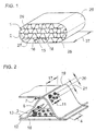
- FIG. 1 shows schematically and in a perspective view of an embodiment of a high-temperature resistant structure 1, as used for example as a carrier body for different coatings 29 for exhaust treatment in the automotive industry.
- the structure 1 here comprises a housing 26, in which a partially structured layer 2 of metal is arranged.
- the layer 2 has smooth and structured subregions and is wound in such a way that channels 28 through which the exhaust gas can flow are formed.
- the smooth sections of the layer 2 form with the structure or corrugation contact points 15, near which finally the solder joints 27 are configured. Further solder joints 27 are formed between the layer 2 and the housing 26. Near the contact points 15, the adjoining or adjoining layer sections form so-called gussets 16 in which ultimately the solder connection 27 is formed.
- the structure 2 has a substantially so-called "race-track” shape, but in principle also round, polygonal or other cross-sectional shapes are possible.
- the structure 1 is formed with layers of an extension 37, which essentially corresponds to an extension of the housing 26, which, however, does not necessarily have to be the case.
- the solder joints 27 are evenly distributed over the cross section of the structure 2. In principle, however, it is possible and is particularly easy to implement by the method proposed here to carry out the structure 1 over the cross section or in the direction of the extension 37 with differently designed solder joints 27. As a result, a particular thermal expansion behavior of the structure 1 under thermal cycling is generated, which may favor the durability of the structure 1.
- FIG. 2 now shows (also in a schematic, perspective view) a detail of a structure 1, with a smooth film 12 and a corrugated foil 13 is formed.
- the smooth sheets 12 and the corrugated sheets 13 are arranged alternately to each other so that in turn channels 28 are formed.
- the corrugated foil 13 in this case has extremes 19, which finally represent the contact points 15 of the smooth foils 12 and the corrugated foils 13.
- gussets 16 are formed, in which the solder material 7 is to be arranged later so that it is present at the contact points for the subsequent formation of joining solder joints 27.
- the films are provided with an adhesive layer 5.
- the adhesive layer 5 is generated with adhesive 3, which is applied drop-shaped.
- the adhesive layers 5 can be made very precisely in accordance with the desired connection section 4.
- the smooth film 12 has been provided with a substantially transversely or perpendicular to the extremum 19 extending adhesive layer 5, which is formed over several corrugations of the corrugated foil 13 contiguous.
- the corrugated foil 13 only very narrow strips are provided near the gussets 16, which are formed with a distance 20 and parallel to the extremes 19.
- the layer width 21 is advantageously in a range of less than 1 mm.
- the illustration is a detail of structure 1 before undergoing thermal treatment to form joining compounds.
- the solder material 7 is provided here as a powder or in the granular form of a predetermined grain fraction, corresponding to the prepared adhesive layers 5, a predetermined amount of solder material 7 remains adhering to the interior of the structure. As a result, it is possible over a length 17 of the gusset 16 to introduce a defined amount of solder. In a subsequent thermal treatment, a large part of the adhesive 3 volatilizes, wherein the solder material 7, which near the Gaps is arranged, which connects adjacent foils to each other and thus ensures a permanent cohesion of the films.
- FIG. 3 schematically shows the application of the adhesive 3 with a nozzle 8 to form an adhesive layer 5 with a layer thickness 6 less than 0.01 mm.
- the application of the adhesive 3 is explained here using the example of a corrugated foil 13.
- the corrugated foil 13 is moved relative to the illustrated nozzles 8, in particular guided between them. This makes it possible to first generate an adhesive layer 5 on a first side 23 of the corrugated foil 13, while subsequently also an adhesive layer 5 can be formed on the second side 24 by means of a further nozzle 8.
- the amount of the adhesive 3 or the embodiment of the adhesive layer 5 takes into account the amount of solder finally desired for the connection, which was also selected with reference to the film thickness 14 of the corrugated foil 13.
- the nozzles 8 are designed to be pivotable and / or relatively movable relative to the corrugated foil 13.
- the nozzles 8 are made changeable with respect to their beam angle 9 and their distance 10.
- the distance of the nozzle opening to the point of impact of the drops 36 of the adhesive 3 is meant.
- the beam angle 9 is determined by the direction of flight of the drops 36 and the perpendicular 35 through the impact point on the corrugated foil 13 and in the desired connection section 4. It should be noted that the distance 10 and the beam angle 9 of the two nozzles 8 respectively can be chosen differently from each other.
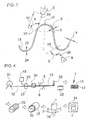
- FIG. 4 schematically shows the sequence of a preferred embodiment of the method for producing a high-temperature resistant structure 1, which has a plurality of smooth sheets 12 and corrugated sheets 13.
- the progress of the process is indicated by white arrows, the figure is constructed line by line and is always read from left to right.
- a smooth film 12 which is stored for example on a coil 30, the desired curl is first introduced into the film 12.
- the smooth film 12 is first brought into contact with oil 18, immediately before the smooth film 12 is passed through intermeshing profile rollers 22 in order to promote the process taking place forming process.
- the now corrugated foil 13 is passed through a furnace 31, whereby the adhering to the corrugated foil 13 oil 18 at least largely volatilizes.
- the corrugated foil 13 thus cleaned is then fed to a system for forming the desired adhesive layers, which is symbolized here by two nozzles 8 arranged on both sides 23, 24 of the corrugated foil 13.
- the adhesive 3 is printed by means of a drop-on-demand method, a bubble-jet method or a continuous-jet method, wherein it is also possible in principle for each nozzle to use a separate method or provide several such processing stations, each forming different adhesive layers and resort to a different method.
- This corrugated foil 13 prepared in this way is then fed to a cutting device 32, which separates the corrugated foil 13 with a predeterminable extent 25.
- the corrugated foils 13 thus produced are alternately stacked with a smooth foil 12 (for example, from another coil 30) to form a structure 1.
- This stack preferably forms channels 28, which are at least partially flowed through for an exhaust gas.
- honeycomb body 33 Such structures 1 are referred to as honeycomb body 33, for example.
- the honeycomb body 33 thus formed or the structure 1 thus formed is now integrated into a housing 26.
- the structure 1 is now on the front side, so for example, through the channels 28 through, with solder 7 in contact brought.
- the desired amount of soldering material 7 sticks to the previously generated adhesive layers 5.
- the honeycomb body 33 thus equipped with solder material or the structure 1 produced in this way is now subjected to a thermal treatment, which in turn is carried out here in an oven 31. This is preferably the high-temperature vacuum brazing.
- the method described here is particularly suitable for the production of thermally and dynamically highly loaded metallic honeycomb bodies.
- the achievable accuracy with respect to the formation of adhesive layers and the resulting targeted introduction of a desired Lotmenge to desired positions allows a very precise vote of the solder joints on the respective field of application encountered.
- the service life of such structures in exhaust systems of automobiles is extended or the production is made more cost-efficient, since in each case only as much solder material is introduced as is actually required for the connection.
Landscapes
- Engineering & Computer Science (AREA)
- Mechanical Engineering (AREA)
- Chemical & Material Sciences (AREA)
- Combustion & Propulsion (AREA)
- General Engineering & Computer Science (AREA)
- Laminated Bodies (AREA)
- Catalysts (AREA)
- Application Of Or Painting With Fluid Materials (AREA)
- Lining Or Joining Of Plastics Or The Like (AREA)
Applications Claiming Priority (2)
| Application Number | Priority Date | Filing Date | Title |
|---|---|---|---|
| DE102004021037A DE102004021037A1 (de) | 2004-04-29 | 2004-04-29 | Verfahren zur Herstellung einer hochtemperaturfesten Struktur |
| PCT/EP2005/004336 WO2005107992A1 (de) | 2004-04-29 | 2005-04-22 | Applikation von haftmittel zur herstellung einer hochtemperaturfesten struktur |
Publications (2)
| Publication Number | Publication Date |
|---|---|
| EP1740339A1 EP1740339A1 (de) | 2007-01-10 |
| EP1740339B1 true EP1740339B1 (de) | 2014-11-05 |
Family
ID=34965264
Family Applications (1)
| Application Number | Title | Priority Date | Filing Date |
|---|---|---|---|
| EP05735078.7A Expired - Lifetime EP1740339B1 (de) | 2004-04-29 | 2005-04-22 | Applikation von haftmittel zur herstellung einer hochtemperaturfesten struktur |
Country Status (9)
| Country | Link |
|---|---|
| US (1) | US20070040004A1 (enExample) |
| EP (1) | EP1740339B1 (enExample) |
| JP (1) | JP5117184B2 (enExample) |
| KR (1) | KR101211197B1 (enExample) |
| CN (1) | CN100574954C (enExample) |
| DE (1) | DE102004021037A1 (enExample) |
| RU (1) | RU2381880C2 (enExample) |
| TW (1) | TWI398573B (enExample) |
| WO (1) | WO2005107992A1 (enExample) |
Families Citing this family (6)
| Publication number | Priority date | Publication date | Assignee | Title |
|---|---|---|---|---|
| DE102008047498A1 (de) * | 2008-09-17 | 2010-04-15 | Emitec Gesellschaft Für Emissionstechnologie Mbh | Verfahren zum Löten eines metallischen Wabenkörpers und zur Abgasbehandlung |
| DE102009018825A1 (de) | 2009-04-24 | 2010-10-28 | Emitec Gesellschaft Für Emissionstechnologie Mbh | Blechlage mit Anti-Diffusionsstrukturen und metallischer Wabenkörper mit mindestens einer solchen Blechlage |
| CN102407163A (zh) * | 2010-10-28 | 2012-04-11 | 林雪平 | 一种尾气净化用金属载体及其加工方法 |
| CN103906904B (zh) * | 2011-09-05 | 2017-12-15 | 巴斯夫公司 | 向金属蜂窝载体施用钎焊材料的方法,金属蜂窝载体及其制造方法 |
| PL3789513T3 (pl) * | 2019-09-09 | 2023-09-04 | Sturm Maschinen- & Anlagenbau Gmbh | Urządzenie powlekające i sposób metalicznego powlekania przedmiotów obrabianych |
| CN114161086B (zh) * | 2021-11-30 | 2024-04-12 | 无锡市盛和科技有限公司 | 一种孔道型金属蜂窝载体内芯的生产工艺 |
Family Cites Families (26)
| Publication number | Priority date | Publication date | Assignee | Title |
|---|---|---|---|---|
| US3479731A (en) * | 1967-06-13 | 1969-11-25 | Gen Motors Corp | Brazing method |
| DE2902779C2 (de) * | 1979-01-25 | 1985-09-26 | Süddeutsche Kühlerfabrik Julius Fr. Behr GmbH & Co. KG, 7000 Stuttgart | Matrix für einen katalytischen Reaktor zur Abgasreinigung bei Brennkraftmaschinen |
| ES2010201B3 (es) * | 1986-05-12 | 1989-11-01 | Interatom Ges Mit Beschrankter Haftung | Cuerpo alveolado, especialmente cuerpo portante de catalizador, con capas de chapa metalica entrelazadas en sentidos opuestos y procedimiento para su fabricacion. |
| JP2545564B2 (ja) * | 1987-12-28 | 1996-10-23 | 臼井国際産業株式会社 | 排気ガス浄化用触媒を担持するための金属製担持母体の製造方法 |
| DE3818512A1 (de) | 1988-05-31 | 1989-12-07 | Interatom | Verfahren zum beleimen und beloten eines metallischen katalysator-traegerkoerpers und zugehoerige vorrichtung |
| BR8907458A (pt) * | 1988-09-22 | 1991-04-02 | Emitec Emissionstechnologie | Corpo alveolar,especialmente corpo de suporte de catalisador,constituido de uma multiplicidade de pilhas de chapa entrelacadas |
| EP0437626B1 (en) * | 1989-08-04 | 1994-12-28 | Showa Aircraft Industry Co., Ltd. | Heat resistant structure and method of manufacture thereof |
| JPH04141238A (ja) * | 1990-10-01 | 1992-05-14 | Nippon Steel Corp | 任意位置に接合部を選択できる金属担体の製造方法 |
| US5224644A (en) * | 1991-12-16 | 1993-07-06 | Thomas P. Mahoney | Method and apparatus for installation of honeycomb core seals |
| DE4219145C1 (de) * | 1992-06-11 | 1994-03-17 | Emitec Emissionstechnologie | Verfahren und Vorrichtung zum Beloten eines metallischen Wabenkörpers |
| DE4231338A1 (de) * | 1992-09-18 | 1994-03-24 | Emitec Emissionstechnologie | Verfahren zum Beloten einer metallischen Struktur, insbesondere von Teilbereichen eines Wabenkörpers |
| JP2709789B2 (ja) * | 1993-06-07 | 1998-02-04 | 日本冶金工業株式会社 | 耐熱疲労性、耐振性に優れた排ガス浄化用メタル担体及びその製造方法 |
| US5593646A (en) * | 1993-06-07 | 1997-01-14 | Nippon Yakin Kogyo Co., Ltd. | Method for producing an exhaust gas cleaning metal carrier |
| DE4416539C1 (de) * | 1994-05-10 | 1995-07-20 | Emitec Emissionstechnologie | Verfahren zum Beloten von metallischen Strukturen mit einem reversibel unterschiedliche Zustände aufweisenden Haftmaterial |
| US5560543A (en) * | 1994-09-19 | 1996-10-01 | Board Of Regents, The University Of Texas System | Heat-resistant broad-bandwidth liquid droplet generators |
| DE19605578C2 (de) * | 1996-02-15 | 2001-03-29 | Dystar Textilfarben Gmbh & Co | Verfahren zur Herstellung eines anionischen Textilfarbstoffen bedruckten textilen Materials |
| DE19642946A1 (de) * | 1996-10-17 | 1998-04-23 | Emitec Emissionstechnologie | Metallischer Wabenkörper und Verfahren zu dessen Herstellung |
| DE19643934A1 (de) * | 1996-10-30 | 1998-05-07 | Emitec Emissionstechnologie | Verfahren und Vorrichtung zum Herstellen strukturierter Metallbleche |
| DE19903184A1 (de) * | 1999-01-27 | 2000-08-03 | Emitec Emissionstechnologie | Metallfolienverbindung und Metallfolien-Lotkornfraktion für Metallfolien |
| US20010032887A1 (en) * | 1999-02-19 | 2001-10-25 | Everett Alan L. | Precision dispensing tip and method |
| DE19943976A1 (de) * | 1999-09-14 | 2001-03-15 | Emitec Emissionstechnologie | Verfahren und Vorrichtung zur stirnseitigen fügetechnischen Verbindung einer Trägermatrix eines Wabenkörpers |
| TW552171B (en) * | 2001-01-19 | 2003-09-11 | Komatsu Mfg Co Ltd | Soldering paste coating method and coating apparatus |
| US6617045B2 (en) * | 2001-03-02 | 2003-09-09 | Nippon Steel Corporation | Metallic carrier, for automobile exhaust gas purification, made of thin metal foil and method of producing the same |
| DE10122082C1 (de) * | 2001-05-07 | 2002-11-14 | Emitec Emissionstechnologie | Blechfolie mit Gleitstruktur, Wabenkörper und Verfahren zu seiner Herstellung |
| DE10151487C1 (de) * | 2001-10-18 | 2002-10-02 | Emitec Emissionstechnologie | Verfahren zur Herstellung einer metallischen Struktur sowie Vorrichtung zur Benetzung einer metallischen Struktur mit einem Klebstoff |
| DE10200069A1 (de) * | 2002-01-03 | 2003-07-24 | Emitec Emissionstechnologie | Wabenstruktur und Verfahren zu deren Beleimung und Belotung |
-
2004
- 2004-04-29 DE DE102004021037A patent/DE102004021037A1/de not_active Withdrawn
-
2005
- 2005-04-13 TW TW094111632A patent/TWI398573B/zh not_active IP Right Cessation
- 2005-04-22 RU RU2006142029/02A patent/RU2381880C2/ru not_active IP Right Cessation
- 2005-04-22 JP JP2007509941A patent/JP5117184B2/ja not_active Expired - Fee Related
- 2005-04-22 WO PCT/EP2005/004336 patent/WO2005107992A1/de not_active Ceased
- 2005-04-22 CN CN200580013076A patent/CN100574954C/zh not_active Expired - Lifetime
- 2005-04-22 EP EP05735078.7A patent/EP1740339B1/de not_active Expired - Lifetime
-
2006
- 2006-10-30 US US11/590,601 patent/US20070040004A1/en not_active Abandoned
- 2006-11-29 KR KR1020067025151A patent/KR101211197B1/ko not_active Expired - Fee Related
Also Published As
| Publication number | Publication date |
|---|---|
| RU2381880C2 (ru) | 2010-02-20 |
| KR101211197B1 (ko) | 2012-12-11 |
| CN1946505A (zh) | 2007-04-11 |
| JP2007534500A (ja) | 2007-11-29 |
| TW200613637A (en) | 2006-05-01 |
| TWI398573B (zh) | 2013-06-11 |
| JP5117184B2 (ja) | 2013-01-09 |
| DE102004021037A1 (de) | 2005-11-24 |
| EP1740339A1 (de) | 2007-01-10 |
| RU2006142029A (ru) | 2008-08-20 |
| WO2005107992A1 (de) | 2005-11-17 |
| CN100574954C (zh) | 2009-12-30 |
| US20070040004A1 (en) | 2007-02-22 |
| KR20070012727A (ko) | 2007-01-26 |
Similar Documents
| Publication | Publication Date | Title |
|---|---|---|
| EP1463599B1 (de) | Wabenstruktur und verfahren zu deren beleimung und belotung | |
| EP2422058B1 (de) | Mehrstufig beheizbarer wabenkörper | |
| EP2823165B1 (de) | Wabenkörper zur abgasnachbehandlung | |
| DE69721326T2 (de) | Katalytischer metallwabenkörper zur abgasreinigung und dessen herstellung | |
| EP0660768A1 (de) | Verfahren zum beloten einer metallischen struktur, insbesondere von teilbereichen eines wabenkörpers. | |
| EP1740339B1 (de) | Applikation von haftmittel zur herstellung einer hochtemperaturfesten struktur | |
| EP1212163B1 (de) | Verfahren zur herstellung eines gesinterten wabenkörpers | |
| EP2260190B1 (de) | Wabenkörper und verfahren zur herstellung eines gelöteten wabenkörpers | |
| EP1981675B1 (de) | Verfahren zur herstellung eines metallteils | |
| EP1934011B1 (de) | Verfahren und vorrichtung zur hartlot-applikation | |
| EP2311598A1 (de) | Wabenkörper-Herstellung mit einem metallischen Vlies | |
| EP1742756B1 (de) | Applikation von gleitmittel zur herstellung einer hochtemperaturfesten struktur | |
| WO2003087549A1 (de) | Kalibrierter katalysator-trägerkörper mit wellmantel und verfahren zu dessen herstellung | |
| EP1633506B1 (de) | Verfahren und vorrichtung zur herstellung eines strukturierten blechbandes | |
| EP1663560B1 (de) | Verfahren und vorrichtung zur herstellung eines wabenkörpers | |
| EP1386066B1 (de) | Wabenkörper und verfahren zu seiner herstellung | |
| DE102009018825A1 (de) | Blechlage mit Anti-Diffusionsstrukturen und metallischer Wabenkörper mit mindestens einer solchen Blechlage | |
| EP4226224B1 (de) | Verfahren zum herstellen eines teilweise additiv gefertigten bauteils für eine technische vorrichtung | |
| EP1529934B1 (de) | Verfahren zur Herstellung eines Katalysatorkörpers und durch das Verfahren herstellbarer Katalysatorkörper | |
| DE10192358B4 (de) | Blech mit Barriere für einen Wabenkörper | |
| DE10239205A1 (de) | Verfahren und Vorrichtung zur Herstellung von Wabenkörpern und Wabenkörper | |
| EP1706230B1 (de) | Fluid-umformung von metallblechen | |
| DE102024108910A1 (de) | Wabenstruktur und Verfahren zur Herstellung einer strukturierten Lage | |
| EP1551534A1 (de) | Katalysator-trägerkörper mit passivierungsschicht sowie verfahren zu dessen herstellung | |
| DE102023134520A1 (de) | Verfahren zum Beleimen einer ersten Lage und eine Wabenstruktur |
Legal Events
| Date | Code | Title | Description |
|---|---|---|---|
| PUAI | Public reference made under article 153(3) epc to a published international application that has entered the european phase |
Free format text: ORIGINAL CODE: 0009012 |
|
| 17P | Request for examination filed |
Effective date: 20060915 |
|
| AK | Designated contracting states |
Kind code of ref document: A1 Designated state(s): DE ES FR GB IT PL |
|
| DAX | Request for extension of the european patent (deleted) | ||
| RBV | Designated contracting states (corrected) |
Designated state(s): DE ES FR GB IT PL |
|
| 17Q | First examination report despatched |
Effective date: 20080408 |
|
| GRAP | Despatch of communication of intention to grant a patent |
Free format text: ORIGINAL CODE: EPIDOSNIGR1 |
|
| INTG | Intention to grant announced |
Effective date: 20140714 |
|
| GRAS | Grant fee paid |
Free format text: ORIGINAL CODE: EPIDOSNIGR3 |
|
| GRAA | (expected) grant |
Free format text: ORIGINAL CODE: 0009210 |
|
| AK | Designated contracting states |
Kind code of ref document: B1 Designated state(s): DE ES FR GB IT PL |
|
| REG | Reference to a national code |
Ref country code: GB Ref legal event code: FG4D Free format text: NOT ENGLISH |
|
| REG | Reference to a national code |
Ref country code: DE Ref legal event code: R081 Ref document number: 502005014579 Country of ref document: DE Owner name: CONTINENTAL AUTOMOTIVE GMBH, DE Free format text: FORMER OWNER: EMITEC GESELLSCHAFT FUER EMISSIONSTECHNOLOGIE MBH, 53797 LOHMAR, DE |
|
| REG | Reference to a national code |
Ref country code: DE Ref legal event code: R096 Ref document number: 502005014579 Country of ref document: DE Effective date: 20141218 |
|
| PG25 | Lapsed in a contracting state [announced via postgrant information from national office to epo] |
Ref country code: ES Free format text: LAPSE BECAUSE OF FAILURE TO SUBMIT A TRANSLATION OF THE DESCRIPTION OR TO PAY THE FEE WITHIN THE PRESCRIBED TIME-LIMIT Effective date: 20141105 |
|
| PG25 | Lapsed in a contracting state [announced via postgrant information from national office to epo] |
Ref country code: PL Free format text: LAPSE BECAUSE OF FAILURE TO SUBMIT A TRANSLATION OF THE DESCRIPTION OR TO PAY THE FEE WITHIN THE PRESCRIBED TIME-LIMIT Effective date: 20141105 |
|
| REG | Reference to a national code |
Ref country code: DE Ref legal event code: R097 Ref document number: 502005014579 Country of ref document: DE |
|
| PLBE | No opposition filed within time limit |
Free format text: ORIGINAL CODE: 0009261 |
|
| STAA | Information on the status of an ep patent application or granted ep patent |
Free format text: STATUS: NO OPPOSITION FILED WITHIN TIME LIMIT |
|
| 26N | No opposition filed |
Effective date: 20150806 |
|
| REG | Reference to a national code |
Ref country code: DE Ref legal event code: R081 Ref document number: 502005014579 Country of ref document: DE Owner name: VITESCO TECHNOLOGIES GMBH, DE Free format text: FORMER OWNER: EMITEC GESELLSCHAFT FUER EMISSIONSTECHNOLOGIE MBH, 53797 LOHMAR, DE Ref country code: DE Ref legal event code: R082 Ref document number: 502005014579 Country of ref document: DE Ref country code: DE Ref legal event code: R081 Ref document number: 502005014579 Country of ref document: DE Owner name: CONTINENTAL AUTOMOTIVE GMBH, DE Free format text: FORMER OWNER: EMITEC GESELLSCHAFT FUER EMISSIONSTECHNOLOGIE MBH, 53797 LOHMAR, DE |
|
| REG | Reference to a national code |
Ref country code: FR Ref legal event code: PLFP Year of fee payment: 12 |
|
| REG | Reference to a national code |
Ref country code: GB Ref legal event code: 732E Free format text: REGISTERED BETWEEN 20160331 AND 20160406 |
|
| REG | Reference to a national code |
Ref country code: FR Ref legal event code: PLFP Year of fee payment: 13 |
|
| PGFP | Annual fee paid to national office [announced via postgrant information from national office to epo] |
Ref country code: GB Payment date: 20170419 Year of fee payment: 13 |
|
| REG | Reference to a national code |
Ref country code: FR Ref legal event code: PLFP Year of fee payment: 14 |
|
| GBPC | Gb: european patent ceased through non-payment of renewal fee |
Effective date: 20180422 |
|
| PG25 | Lapsed in a contracting state [announced via postgrant information from national office to epo] |
Ref country code: GB Free format text: LAPSE BECAUSE OF NON-PAYMENT OF DUE FEES Effective date: 20180422 |
|
| REG | Reference to a national code |
Ref country code: DE Ref legal event code: R081 Ref document number: 502005014579 Country of ref document: DE Owner name: EMITEC TECHNOLOGIES GMBH, DE Free format text: FORMER OWNER: CONTINENTAL AUTOMOTIVE GMBH, 30165 HANNOVER, DE Ref country code: DE Ref legal event code: R081 Ref document number: 502005014579 Country of ref document: DE Owner name: VITESCO TECHNOLOGIES GMBH, DE Free format text: FORMER OWNER: CONTINENTAL AUTOMOTIVE GMBH, 30165 HANNOVER, DE |
|
| REG | Reference to a national code |
Ref country code: DE Ref legal event code: R081 Ref document number: 502005014579 Country of ref document: DE Owner name: EMITEC TECHNOLOGIES GMBH, DE Free format text: FORMER OWNER: VITESCO TECHNOLOGIES GMBH, 30165 HANNOVER, DE Ref country code: DE Ref legal event code: R081 Ref document number: 502005014579 Country of ref document: DE Owner name: VITESCO TECHNOLOGIES GMBH, DE Free format text: FORMER OWNER: VITESCO TECHNOLOGIES GMBH, 30165 HANNOVER, DE |
|
| REG | Reference to a national code |
Ref country code: DE Ref legal event code: R084 Ref document number: 502005014579 Country of ref document: DE |
|
| P01 | Opt-out of the competence of the unified patent court (upc) registered |
Effective date: 20230530 |
|
| REG | Reference to a national code |
Ref country code: DE Ref legal event code: R081 Ref document number: 502005014579 Country of ref document: DE Owner name: EMITEC TECHNOLOGIES GMBH, DE Free format text: FORMER OWNER: VITESCO TECHNOLOGIES GMBH, 93055 REGENSBURG, DE Ref country code: DE Ref legal event code: R082 Ref document number: 502005014579 Country of ref document: DE Representative=s name: KARO IP PATENTANWAELTE KAHLHOEFER ROESSLER KRE, DE Ref country code: DE Ref legal event code: R082 Ref document number: 502005014579 Country of ref document: DE Representative=s name: KARO IP PATENTANWAELTE PARTG MBB, DE |
|
| PGFP | Annual fee paid to national office [announced via postgrant information from national office to epo] |
Ref country code: DE Payment date: 20240425 Year of fee payment: 20 |
|
| PGFP | Annual fee paid to national office [announced via postgrant information from national office to epo] |
Ref country code: IT Payment date: 20240426 Year of fee payment: 20 Ref country code: FR Payment date: 20240423 Year of fee payment: 20 |
|
| REG | Reference to a national code |
Ref country code: DE Ref legal event code: R071 Ref document number: 502005014579 Country of ref document: DE |