EP1739808A2 - System and method for protecting magnetic elements of an electrical machine from demagnetization - Google Patents
System and method for protecting magnetic elements of an electrical machine from demagnetization Download PDFInfo
- Publication number
- EP1739808A2 EP1739808A2 EP06253388A EP06253388A EP1739808A2 EP 1739808 A2 EP1739808 A2 EP 1739808A2 EP 06253388 A EP06253388 A EP 06253388A EP 06253388 A EP06253388 A EP 06253388A EP 1739808 A2 EP1739808 A2 EP 1739808A2
- Authority
- EP
- European Patent Office
- Prior art keywords
- magnetic
- assembly
- electrically conductive
- rotor core
- magnetic element
- Prior art date
- Legal status (The legal status is an assumption and is not a legal conclusion. Google has not performed a legal analysis and makes no representation as to the accuracy of the status listed.)
- Withdrawn
Links
Images



Classifications
-
- H—ELECTRICITY
- H02—GENERATION; CONVERSION OR DISTRIBUTION OF ELECTRIC POWER
- H02K—DYNAMO-ELECTRIC MACHINES
- H02K1/00—Details of the magnetic circuit
- H02K1/06—Details of the magnetic circuit characterised by the shape, form or construction
- H02K1/22—Rotating parts of the magnetic circuit
- H02K1/27—Rotor cores with permanent magnets
- H02K1/2706—Inner rotors
- H02K1/272—Inner rotors the magnetisation axis of the magnets being perpendicular to the rotor axis
- H02K1/274—Inner rotors the magnetisation axis of the magnets being perpendicular to the rotor axis the rotor consisting of two or more circumferentially positioned magnets
- H02K1/2753—Inner rotors the magnetisation axis of the magnets being perpendicular to the rotor axis the rotor consisting of two or more circumferentially positioned magnets the rotor consisting of magnets or groups of magnets arranged with alternating polarity
- H02K1/278—Surface mounted magnets; Inset magnets
-
- H—ELECTRICITY
- H02—GENERATION; CONVERSION OR DISTRIBUTION OF ELECTRIC POWER
- H02K—DYNAMO-ELECTRIC MACHINES
- H02K1/00—Details of the magnetic circuit
- H02K1/06—Details of the magnetic circuit characterised by the shape, form or construction
- H02K1/22—Rotating parts of the magnetic circuit
- H02K1/24—Rotor cores with salient poles ; Variable reluctance rotors
-
- H—ELECTRICITY
- H02—GENERATION; CONVERSION OR DISTRIBUTION OF ELECTRIC POWER
- H02K—DYNAMO-ELECTRIC MACHINES
- H02K3/00—Details of windings
- H02K3/04—Windings characterised by the conductor shape, form or construction, e.g. with bar conductors
- H02K3/12—Windings characterised by the conductor shape, form or construction, e.g. with bar conductors arranged in slots
- H02K3/16—Windings characterised by the conductor shape, form or construction, e.g. with bar conductors arranged in slots for auxiliary purposes, e.g. damping or commutating
-
- H—ELECTRICITY
- H02—GENERATION; CONVERSION OR DISTRIBUTION OF ELECTRIC POWER
- H02K—DYNAMO-ELECTRIC MACHINES
- H02K15/00—Processes or apparatus specially adapted for manufacturing, assembling, maintaining or repairing of dynamo-electric machines
- H02K15/02—Processes or apparatus specially adapted for manufacturing, assembling, maintaining or repairing of dynamo-electric machines of stator or rotor bodies
- H02K15/03—Processes or apparatus specially adapted for manufacturing, assembling, maintaining or repairing of dynamo-electric machines of stator or rotor bodies having permanent magnets
Definitions
- the present invention relates generally to magnetic elements formed from permanent magnet materials in electrical machines and, more specifically to systems and methods for protecting these elements from demagnetization, such as large electric machines with high pole counts and low rated frequencies.
- Electrical machines such as motors and generators, often include a rotor disposed within a stator.
- these rotors generally include magnetic elements mounted thereto. These magnetic elements facilitate the conversion of electrical energy to kinetic energy and vice-versa.
- the kinetic energy of the rotor's rotation is converted into electrical energy by inducing electric voltage and current in the stator windings.
- the magnetic elements in the rotor are subjected to strong demagnetization fields. That is, fault conditions often generate magnetic fields opposite to the magnetic fields produced by the magnet elements. Unfortunately, these newly generated magnetic fields tend to demagnetize the magnetic elements, for instance.
- the edges of the magnetic elements are susceptible to a decrease in the component of the magnetic flux parallel to the magnetization direction of the magnet (typically the radial direction) and as such, a loss of magnetization.
- decrease in magnetic flux beyond a certain level can cause irreversible demagnetization of the magnetic elements.
- Irreversible demagnetization results in reduced power and torque capability of the electrical machine and can require disassembly and remagnetization to restore the electrical machine to its original condition.
- irreversible demagnetization increases the downtime of the electrical machine as well as the adding the cost of the remagnetization.
- irreversible demagnetization is generally an undesirable event.
- demagnetization protection has been provided by circumferentially surrounding the rotor with an electrically conductive, non-ferromagnetic material, such as an alloy containing copper or aluminum.
- This overlaying shield facilitates the production of a magnetic field in opposition to the fault producing magnetic field, thereby protecting the magnetic elements from demagnetization.
- the thickness of the shield is on the order of a skin depth at rated frequency. Thus for low frequency machines (e.g., ⁇ 15Hz), the shield may be unacceptably thick.
- these traditional shields increase the effective air gap distance between magnetic elements and the stator windings, since they are non-ferromagnetic.
- magnetic flux from the magnetic elements does not well travel through the non-magnetic shield, reducing the overall performance capability of the electrical machine.
- these traditional shields require an increase in the magnet thickness (i.e., length along the magnetization axis), overall magnet mass and, as such, cost for achieving a desired air gap flux density and machine performance, for example.
- the present technique provides a magnetic assembly for an electrical machine having a rotor core.
- the magnetic assembly includes a magnetic element having a top surface, a bottom surface and at least one side surface located between the top and bottom surfaces, wherein the bottom surface of the magnetic element is couplable to a peripheral surface of the rotor core.
- the magnetic assembly also includes a ferromagnetic layer disposed on the top surface of the magnetic element.
- the magnetic assembly further includes an electrically conductive element that circumscribes magnetic element.
- a method of manufacturing a magnetic assembly for a rotor assembly of an electrical machine includes providing a magnetic element having a top surface, a bottom surface and at least one side surface extending between the top and bottom surfaces.
- the method includes disposing a ferromagnetic layer over the top surface of the magnetic element.
- the method further includes disposing an electrically conductive element that circumscribes the magnetic element
- the present technique is generally directed towards protecting magnetic elements from demagnetizing factors that often occur in electrical machines.
- the present technique provides many benefits, and it should not be limited to the embodiments described herein. Indeed, magnetic elements, exemplary embodiments of which are discussed further below, are used in many applications, such as motors, generators, to name but few applications.
- FIG. 1 is a partial, perspective view of the rotor assembly 14, in accordance with an exemplary embodiment of the present technique.
- the exemplary rotor assembly 14 includes a rotor core 18 with a rotor frame 19.
- the outer peripheral surface 32 of the rotor core 18 carries a series of magnetic assemblies 20 that circumferentially surround the rotor core 18.
- These magnetic assemblies 20 are secured to the rotor core with wedges 34, which are formed of a non-ferromagnetic material such as aramid fiber.
- the wedges 34 may be formed of any suitable material.
- the wedges 34 include mounting holes 36 that align with mounting holes 38 in the rotor core 18 when assembled.
- Either holes 36 or 38 can be tapped with screw threads or augmented with screw thread inserts to provide mounting of the magnetic assemblies to the rotor core 18 via mounting bolts.
- the wedges 34 and the magnetic assemblies may have correspondingly profiled surfaces for a good fit there between.
- FIG. 2 is an exploded, perspective view of the magnetic assembly 20, in accordance with an exemplary embodiment of the present technique.
- the magnetic assembly 20 includes magnetic elements 40, which, as described above, generate magnetic flux.
- the magnetic elements 40 may be formed by subjecting a magnetically hard material to a strong magnetic field, causing the magnetic material to retain its magnetic field producing properties, thus becoming what is commonly referred to as a permanent magnet.
- magnetic fields that are produced by the armature currents in opposition to the magnetic field of the magnetic elements tend to demagnetize the magnetic elements, especially under short circuit fault scenarios.
- a short-circuit in the stator assembly 22 can produce a sudden transient magnetic field that is opposite to the magnetic field of the magnetic elements 40.
- the exemplary magnetic assembly includes an electrically conductive element or electrically conductive rings 42 that circumscribe each of the magnetic elements 40.
- Each of the electrically conductive rings 42 includes at least one effective turn.
- the electrically conductive rings 42 may be formed of copper, aluminum, or any combinations thereof or an alloy containing one or more of those elements.
- the cross-section of the electrically conductive rings 42 may be a circle or a polygon. As illustrated, the electrically conductive rings 42 circumscribe the side surfaces 44, 46, 48 and 50 of the magnetic elements.
- the magnetic field resultantly produced induces current in the electrically conductive rings 42 that, in turn, produce a magnetic field opposite to the magnetic field produced by the short-circuit, reducing the demagnetizing effect of the short-circuit on the magnetic elements 40 thus providing a shielding effect to protect the magnetic element with out increasing the reluctance of the magnetic path.
- the electrically conductive rings 42 or loops do not extend to cover the top surface 52 of the magnetic elements 40. Accordingly, the electrically conductive rings 42 do not add to the reluctance of the magnetic circuit linking the magnetic elements 40 and the stator windings 28.
- the magnetic assemblies 20 include a pole-cap 54.
- the pole-cap 54 may be formed of a ferromagnetic magnetically soft material with preferably low electrical conductivity; e.g., soft-magnetic composite (SMC), a plurality of laminations formed of mild or electrical steel, or any combinations thereof.
- SMC soft-magnetic composite
- the pole-cap 54 provides protection against demagnetization partially, i.e. near a top surface 52 of the magnetic elements 40 by providing a high permeance quadrature-axis flux path through the air gap.
- the pole-cap also distributes the direct-axis demagnetizing flux (i.e., field) uniformly across the magnet surface, thereby attenuating localized demagnetization.
- the direct axis is defined under conventional electrical machine terminology as the orientation axis on the rotor whereby the magnetic flux from the magnetic elements (i.e., permanent magnets) is aligned.
- the quadrature axis is located orthogonal (i.e., 90 electrical degrees) from the direct axis.
- the pole-cap 54 can increase the stator winding leakage flux, and the resulting synchronous, transient, and sub-transient reactances, which thereby limit the magnitude of the fault currents, and the level of demagnetizing forces.
- the pole cap 54 may also be formed of solid ferromagnetic steel though with the drawback of higher electrical losses (and lower generator efficiency and increased heating) due to induced eddy current in the pole cap steel especially during rated and partial load operation.
- An optional back plate 56 formed of a magnetically soft material such as solid mild steel is provided to add structural integrity to the magnet assembly.
- the magnetic elements 40, the electrically conductive rings 42, the pole-cap 54, and the back plate 56 may be coupled using resin.
- the magnetic assembly 20 may include a plurality of magnetic elements 40 each surrounded by one electrically conductive ring 42. While in other embodiments, the magnetic assembly 20 may include one or more magnetic elements 40 all surrounded by one electrically conductive ring 40.
- FIG. 3 is a partial sectional view of an electrical machine having a stator and rotor.
- the rotor core 18 is coupled to magnetic elements 40 along with pole-caps 54. Air gap 30 separates the stator 22 from the magnetic elements 40.
- the magnetic assembly 20 contains one electrically conductive ring which surrounds all magnetic elements 40.
- Stator yoke 24, slot 26, slot wedge 27 and stator tooth 28 are also shown in FIG. 3. The demagnetization effects at the instant of time of peak short circuit current and comparisons of the present exemplary embodiments with the prior art are described in further detail below with reference to FIG. 4A, FIG. 4B, FIG. 5A and FIG. 5B.
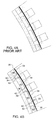
- FIG. 4A is a three pole flux diagram indicating a manner in which the flux lines are distributed at the instant of peak short circuit current in the vicinity of the air gap for a magnet assembly as implemented in prior art not containing a single or multiple conductive rings 42.
- the side surfaces of the magnet elements 40 as illustrated in FIG. 4, are not circumscribed by any electrically conductive material but instead surrounded by air or by non-electrically conductive materials.
- the magnetic elements 40 in such an assembly have reduced radial components of the magnetic flux.
- the magnets are susceptible to demagnetizing effect, especially near the edges.
- FIG. 4B is a three pole flux diagram indicating a manner in which the flux lines are distributed at the instant of peak short circuit current in the vicinity of the air gap in magnetic elements 40 according to an exemplary embodiment of the invention.
- the side surfaces of the magnetic elements 40 are circumscribed by a conductor ring 42.
- the high density of flux lines and the radial orientation of these flux lines indicate the presence of strong magnetic fields produced by the magnet elements.
- the presence of the magnetic fields ensures that the demagnetization effects due to the sudden fault condition are substantially reduced.
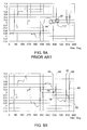
- the associated waveform plots of the radial (the direction of intended magnetization for this example) flux density shown in FIG. 5A and FIG. 5B quantify the improvements in protection from demagnetization.
- FIG. 5A is a graph illustrating the radial component of the magnet flux density along the surface of the magnets, with the three pole flux diagram in FIG. 4A commencing at 360 electrical degrees.
- the X-axis represents the circumferential distance in electrical degrees and the Y-axis represents the flux density in Tesla.
- the vertical lines represent the edges of the magnet assembly implemented in the prior art.
- the area of the magnet that is potentially irreversibly demagnetized is indicated by regions 64 and 66, where the flux density approaches zero or even reversed polarities.
- regions 64 and 66 where the flux density approaches zero or even reversed polarities.
- FIG. 5A a large portion of the magnet is exposed to irreversible demagnetization effects due to a sudden fault or short circuit condition in the electrical machine.
- the actual amount of irreversible demagnetization of the magnet will be dependent upon the specific magnet material chosen. In general, magnet material with high intrinsic coercivity is more resistant to irreversibly demagnetization, but also have lower energy product or higher cost
- FIG. 5B is a graph illustrating the radial component of the magnetic flux density along the surface of the magnets with the three pole flux diagram in FIG. 4B commencing at 360 electrical degrees, in accordance with one embodiment of the present invention.
- the X-axis again represents the circumferential distance in electrical degrees and the Y-axis represents the flux density in Tesla.
- the peak points 76, 78, 80 and 82 represent the magnetic flux density at the edges 59, 60, 61 and 62 of the magnetic pole respectively.
- the area of the magnet exposed to the irreversible demagnetization effect is greatly reduced, if not eliminated, due to the counter flux introduced by the conductive ring disposed around the magnet assembly.
- FIG. 6 is a partial, perspective view of another rotor assembly 87, similar to the rotor assembly 14 for an electrical machine, in accordance with an exemplary embodiment of the present technique.
- the rotor assembly 87 includes a rotor core 18 and a plurality of magnetic assemblies 20.
- the magnetic assemblies 20 include several magnetic elements 40.
- the rotor core 18 also includes a plurality of tapped holes 88 on its peripheral surface 90.
- the plurality of magnetic assemblies 20 is assembled to the rotor core 18 using frames 92 and fasteners.
- the frames are preferably a non-ferromagnetic, conductive material such as silver, aluminum, copper, or brass, or an alloy thereof.
- the frames perform the function of the conductive rings 42 described in FIG. 3 above.
- FIG. 7 is a front cross-section of a magnetic assembly 94, similar to the magnetic assembly 20 but with electrically conductive rings imbedded inside a pole-cap, in accordance with an embodiment of the present technique.
- the magnetic assembly 94 includes magnetic element 40.
- the electrically conductive rings 42 are imbedded inside a pole-cap 96.
- the pole-cap 96 is made of a soft magnetic composite (SMC), powder metal material.
- SMC soft magnetic composite
- the pole-cap material along with the electrically conductive rings 42 is compressed to form the pole-cap 96 imbedded with the electrically conductive rings 42.
- the magnetic assembly also includes a back plate 56.
- the pole cap may also be comprised of a laminated steel stack, in which case, slots for the conductive rings are punched into the pole cap laminations prior to assembly.
- FIG. 8 is a front cross-section of another magnetic assembly 98 with electrically conductive rings imbedded inside a pole-cap, in accordance with an embodiment of the present technique.
- the magnetic assembly 98 includes electrically conductive rings 100 with triangular cross-section.
- the pole-cap material (SMC or powder metal) along with the electrically conductive rings 100 having triangular cross-section is compressed to form the pole-cap 102 imbedded with the electrically conductive rings 100.
- electrically conductive rings 100 with triangular cross-section offer low blockage to the magnetic flux of the magnetic element 40 due to small footprint.
- the magnetic assembly 98 also includes the magnetic element 40 and a back plate 56.
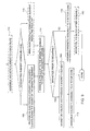
- FIG. 9 is a flowchart illustrating an exemplary method of manufacturing of a rotor assembly for an electrical machine, in accordance with aspects of present technique.
- the method includes magnetizing a block having a top and bottom surfaces to produce a magnetic element, as in step 104.
- the block may also be coupled to the rotor core and then magnetized, as in step 106.
- An electrically conductive ring having at least one effective loop is disposed surrounding the edges of the magnetic element, as in step 108.
- an electrically conductive ring having a rectangular or triangular cross section may be imbedded inside a pole-cap, as in step 110.
- the magnetic element may then be coupled to a back plate, as in step 112.
- a pole-cap is then coupled to the top surface of the magnetic element to produce a magnetic assembly, as in step 114.
- the magnetic assembly is coupled to the rotor core by using a non-magnetic wedge of FIG. 1 or using a frame of FIG. 6, as in step 116.
Landscapes
- Engineering & Computer Science (AREA)
- Power Engineering (AREA)
- Permanent Field Magnets Of Synchronous Machinery (AREA)
- Iron Core Of Rotating Electric Machines (AREA)
Abstract
Description
- The present invention relates generally to magnetic elements formed from permanent magnet materials in electrical machines and, more specifically to systems and methods for protecting these elements from demagnetization, such as large electric machines with high pole counts and low rated frequencies.
- Electrical machines, such as motors and generators, often include a rotor disposed within a stator. In the case of synchronous permanent magnet motors or generators, these rotors generally include magnetic elements mounted thereto. These magnetic elements facilitate the conversion of electrical energy to kinetic energy and vice-versa. For example, in generators, the kinetic energy of the rotor's rotation is converted into electrical energy by inducing electric voltage and current in the stator windings. During fault conditions, such as short circuits, the magnetic elements in the rotor are subjected to strong demagnetization fields. That is, fault conditions often generate magnetic fields opposite to the magnetic fields produced by the magnet elements. Unfortunately, these newly generated magnetic fields tend to demagnetize the magnetic elements, for instance. Particularly, the edges of the magnetic elements are susceptible to a decrease in the component of the magnetic flux parallel to the magnetization direction of the magnet (typically the radial direction) and as such, a loss of magnetization. Indeed, decrease in magnetic flux beyond a certain level can cause irreversible demagnetization of the magnetic elements. Irreversible demagnetization results in reduced power and torque capability of the electrical machine and can require disassembly and remagnetization to restore the electrical machine to its original condition. Thus, irreversible demagnetization increases the downtime of the electrical machine as well as the adding the cost of the remagnetization. In summary, irreversible demagnetization is generally an undesirable event.
- In the past, demagnetization protection has been provided by circumferentially surrounding the rotor with an electrically conductive, non-ferromagnetic material, such as an alloy containing copper or aluminum. This overlaying shield facilitates the production of a magnetic field in opposition to the fault producing magnetic field, thereby protecting the magnetic elements from demagnetization. To be effective the thickness of the shield is on the order of a skin depth at rated frequency. Thus for low frequency machines (e.g., <15Hz), the shield may be unacceptably thick. Unfortunately, these traditional shields increase the effective air gap distance between magnetic elements and the stator windings, since they are non-ferromagnetic. In other words, magnetic flux from the magnetic elements does not well travel through the non-magnetic shield, reducing the overall performance capability of the electrical machine. Indeed, these traditional shields require an increase in the magnet thickness (i.e., length along the magnetization axis), overall magnet mass and, as such, cost for achieving a desired air gap flux density and machine performance, for example.
- Another traditional method for mitigating the risk of demagnetization during a short circuit has been to design the magnetic elements with relatively large thickness so the magnet operates on a steep load line and at a high flux density state. Unfortunately, this results in excessive magnet material mass and, as such, cost. Hence, this option, though widely adopted, is often costly, and not desired for cost sensitive applications.
- Thus, there exists a need for improved systems and methods for providing demagnetization protection to the magnetic elements in electrical machines, especially machines with many poles that operate at typical power generation frequencies (i.e., 60Hz or less).
- Briefly, in accordance with one embodiment, the present technique provides a magnetic assembly for an electrical machine having a rotor core. The magnetic assembly includes a magnetic element having a top surface, a bottom surface and at least one side surface located between the top and bottom surfaces, wherein the bottom surface of the magnetic element is couplable to a peripheral surface of the rotor core. The magnetic assembly also includes a ferromagnetic layer disposed on the top surface of the magnetic element. The magnetic assembly further includes an electrically conductive element that circumscribes magnetic element.
- In accordance with one aspect of the present technique, a method of manufacturing a magnetic assembly for a rotor assembly of an electrical machine is provided. The method includes providing a magnetic element having a top surface, a bottom surface and at least one side surface extending between the top and bottom surfaces. The method includes disposing a ferromagnetic layer over the top surface of the magnetic element. The method further includes disposing an electrically conductive element that circumscribes the magnetic element
- Various features, aspects, and advantages of the present invention will become better understood when the following detailed description is read with reference to the accompanying drawings in which like characters represent like parts throughout the drawings, wherein:
- FIG. 1 is a partial, perspective view of a rotor assembly for an electrical machine, in accordance with an exemplary embodiment of the present technique;
- FIG. 2 is an exploded, perspective view of a magnetic assembly, in accordance with an exemplary embodiment of the present technique;
- FIG. 3 is a partial sectional view of an electrical machine having a stator and rotor, with a fractional number of poles per slot per phase;
- FIG. 4A is a three pole flux diagram indicating a manner in which the flux lines are distributed in a magnet assembly at the instant of peak short circuit fault current as implemented in prior art;
- FIG. 4B is a three pole flux diagram indicating a manner in which the flux lines are distributed in magnet assembly at the instant of peak short circuit fault current according to an embodiment of the present invention;
- FIG. 5A is a graph illustrating the radial component (the magnet is magnetized in the radial direction) of the magnet flux density along the surface of the magnets, with the three pole flux diagram in FIG. 4A commencing at 360 electrical degrees
- FIG. 5B is a graph illustrating the radial component of the magnetic flux density along the surface of the magnets with the three pole flux diagram in FIG. 4B commencing at 360 electrical degrees, in accordance with one embodiment of the present invention;
- FIG. 6 is an exploded, perspective view of another rotor assembly for an electrical machine, in accordance with an exemplary embodiment of the present technique;
- FIG. 7 is a front cross-section of a magnetic assembly with electrically conductive rings imbedded inside a pole-cap, in accordance with an embodiment of the present technique;
- FIG. 8 is a front cross-section of another magnetic assembly with electrically conductive rings imbedded inside a pole-cap, in accordance with an embodiment of the present technique; and
- FIG. 9 is a flowchart illustrating an exemplary method of manufacturing of a rotor assembly for an electrical machine, in accordance with aspects of present technique.
- As a preliminary matter, the definition of the term "or" for the purpose of the following discussion and the appended claims is intended to be an inclusive "or." That is, the term "or" is not intended to differentiate between two mutually exclusive alternatives. Rather, the term "or" when employed as a conjunction between two elements is defined as including one element by itself, the other element itself, and combinations and permutations of the elements. For example, a discussion or recitation employing the terminology "A" or "B" includes: "A", by itself "B" by itself and any combination thereof, such as "AB" and/or "BA."
- The present technique is generally directed towards protecting magnetic elements from demagnetizing factors that often occur in electrical machines. However, it is worth noting that the present technique provides many benefits, and it should not be limited to the embodiments described herein. Indeed, magnetic elements, exemplary embodiments of which are discussed further below, are used in many applications, such as motors, generators, to name but few applications.
- FIG. 1 is a partial, perspective view of the
rotor assembly 14, in accordance with an exemplary embodiment of the present technique. Theexemplary rotor assembly 14 includes arotor core 18 with arotor frame 19. The outerperipheral surface 32 of therotor core 18 carries a series ofmagnetic assemblies 20 that circumferentially surround therotor core 18. Thesemagnetic assemblies 20 are secured to the rotor core withwedges 34, which are formed of a non-ferromagnetic material such as aramid fiber. Of course, thewedges 34 may be formed of any suitable material. Thewedges 34 includemounting holes 36 that align withmounting holes 38 in therotor core 18 when assembled. Eitherholes rotor core 18 via mounting bolts. Indeed, thewedges 34 and the magnetic assemblies may have correspondingly profiled surfaces for a good fit there between. - FIG. 2 is an exploded, perspective view of the
magnetic assembly 20, in accordance with an exemplary embodiment of the present technique. Themagnetic assembly 20 includesmagnetic elements 40, which, as described above, generate magnetic flux. Typically, themagnetic elements 40 may be formed by subjecting a magnetically hard material to a strong magnetic field, causing the magnetic material to retain its magnetic field producing properties, thus becoming what is commonly referred to as a permanent magnet. However, as described above, magnetic fields that are produced by the armature currents in opposition to the magnetic field of the magnetic elements tend to demagnetize the magnetic elements, especially under short circuit fault scenarios. For example, a short-circuit in thestator assembly 22 can produce a sudden transient magnetic field that is opposite to the magnetic field of themagnetic elements 40. - To protect the magnetic elements from such a demagnetizing magnetic field, the exemplary magnetic assembly includes an electrically conductive element or electrically
conductive rings 42 that circumscribe each of themagnetic elements 40. Each of the electrically conductive rings 42 includes at least one effective turn. The electrically conductive rings 42 may be formed of copper, aluminum, or any combinations thereof or an alloy containing one or more of those elements. The cross-section of the electrically conductive rings 42 may be a circle or a polygon. As illustrated, the electricallyconductive rings 42 circumscribe the side surfaces 44, 46, 48 and 50 of the magnetic elements. Thus in the event of a short-circuit, the magnetic field resultantly produced induces current in the electrically conductive rings 42 that, in turn, produce a magnetic field opposite to the magnetic field produced by the short-circuit, reducing the demagnetizing effect of the short-circuit on themagnetic elements 40 thus providing a shielding effect to protect the magnetic element with out increasing the reluctance of the magnetic path. Advantageously, as illustrated, the electricallyconductive rings 42 or loops do not extend to cover thetop surface 52 of themagnetic elements 40. Accordingly, the electricallyconductive rings 42 do not add to the reluctance of the magnetic circuit linking themagnetic elements 40 and thestator windings 28. - Additionally, the
magnetic assemblies 20 include a pole-cap 54. The pole-cap 54 may be formed of a ferromagnetic magnetically soft material with preferably low electrical conductivity; e.g., soft-magnetic composite (SMC), a plurality of laminations formed of mild or electrical steel, or any combinations thereof. The pole-cap 54 provides protection against demagnetization partially, i.e. near atop surface 52 of themagnetic elements 40 by providing a high permeance quadrature-axis flux path through the air gap. The pole-cap also distributes the direct-axis demagnetizing flux (i.e., field) uniformly across the magnet surface, thereby attenuating localized demagnetization. The direct axis is defined under conventional electrical machine terminology as the orientation axis on the rotor whereby the magnetic flux from the magnetic elements (i.e., permanent magnets) is aligned. The quadrature axis is located orthogonal (i.e., 90 electrical degrees) from the direct axis. As will be appreciated by those skilled in the art, the pole-cap 54 can increase the stator winding leakage flux, and the resulting synchronous, transient, and sub-transient reactances, which thereby limit the magnitude of the fault currents, and the level of demagnetizing forces. Thepole cap 54 may also be formed of solid ferromagnetic steel though with the drawback of higher electrical losses (and lower generator efficiency and increased heating) due to induced eddy current in the pole cap steel especially during rated and partial load operation. Anoptional back plate 56 formed of a magnetically soft material such as solid mild steel is provided to add structural integrity to the magnet assembly. - The
magnetic elements 40, the electricallyconductive rings 42, the pole-cap 54, and theback plate 56 may be coupled using resin. In some embodiments, themagnetic assembly 20 may include a plurality ofmagnetic elements 40 each surrounded by one electricallyconductive ring 42. While in other embodiments, themagnetic assembly 20 may include one or moremagnetic elements 40 all surrounded by one electricallyconductive ring 40. - FIG. 3 is a partial sectional view of an electrical machine having a stator and rotor. The
rotor core 18 is coupled tomagnetic elements 40 along with pole-caps 54.Air gap 30 separates thestator 22 from themagnetic elements 40. In FIG. 3 themagnetic assembly 20 contains one electrically conductive ring which surrounds allmagnetic elements 40.Stator yoke 24,slot 26,slot wedge 27 andstator tooth 28 are also shown in FIG. 3. The demagnetization effects at the instant of time of peak short circuit current and comparisons of the present exemplary embodiments with the prior art are described in further detail below with reference to FIG. 4A, FIG. 4B, FIG. 5A and FIG. 5B. - FIG. 4A is a three pole flux diagram indicating a manner in which the flux lines are distributed at the instant of peak short circuit current in the vicinity of the air gap for a magnet assembly as implemented in prior art not containing a single or multiple conductive rings 42. In traditional assemblies, the side surfaces of the
magnet elements 40, as illustrated in FIG. 4, are not circumscribed by any electrically conductive material but instead surrounded by air or by non-electrically conductive materials. During a sudden short circuit condition, themagnetic elements 40 in such an assembly have reduced radial components of the magnetic flux. As a result, the magnets are susceptible to demagnetizing effect, especially near the edges. - FIG. 4B is a three pole flux diagram indicating a manner in which the flux lines are distributed at the instant of peak short circuit current in the vicinity of the air gap in
magnetic elements 40 according to an exemplary embodiment of the invention. In such an embodiment, the side surfaces of themagnetic elements 40 are circumscribed by aconductor ring 42. Thus, as shown in the FIG. 4B, the high density of flux lines and the radial orientation of these flux lines indicate the presence of strong magnetic fields produced by the magnet elements. The presence of the magnetic fields ensures that the demagnetization effects due to the sudden fault condition are substantially reduced. The associated waveform plots of the radial (the direction of intended magnetization for this example) flux density shown in FIG. 5A and FIG. 5B quantify the improvements in protection from demagnetization. - FIG. 5A is a graph illustrating the radial component of the magnet flux density along the surface of the magnets, with the three pole flux diagram in FIG. 4A commencing at 360 electrical degrees. The X-axis represents the circumferential distance in electrical degrees and the Y-axis represents the flux density in Tesla. The vertical lines represent the edges of the magnet assembly implemented in the prior art. The area of the magnet that is potentially irreversibly demagnetized is indicated by
regions - FIG. 5B is a graph illustrating the radial component of the magnetic flux density along the surface of the magnets with the three pole flux diagram in FIG. 4B commencing at 360 electrical degrees, in accordance with one embodiment of the present invention. The X-axis again represents the circumferential distance in electrical degrees and the Y-axis represents the flux density in Tesla. The peak points 76, 78, 80 and 82 represent the magnetic flux density at the
edges - FIG. 6 is a partial, perspective view of another
rotor assembly 87, similar to therotor assembly 14 for an electrical machine, in accordance with an exemplary embodiment of the present technique. As described above, therotor assembly 87 includes arotor core 18 and a plurality ofmagnetic assemblies 20. Themagnetic assemblies 20 include severalmagnetic elements 40. Therotor core 18 also includes a plurality of tappedholes 88 on itsperipheral surface 90. In the exemplary embodiment, the plurality ofmagnetic assemblies 20 is assembled to therotor core 18 usingframes 92 and fasteners. The frames are preferably a non-ferromagnetic, conductive material such as silver, aluminum, copper, or brass, or an alloy thereof. The frames perform the function of the conductive rings 42 described in FIG. 3 above. - FIG. 7 is a front cross-section of a
magnetic assembly 94, similar to themagnetic assembly 20 but with electrically conductive rings imbedded inside a pole-cap, in accordance with an embodiment of the present technique. Themagnetic assembly 94 includesmagnetic element 40. The electrically conductive rings 42 are imbedded inside a pole-cap 96. The pole-cap 96 is made of a soft magnetic composite (SMC), powder metal material. The pole-cap material along with the electrically conductive rings 42 is compressed to form the pole-cap 96 imbedded with the electrically conductive rings 42. The magnetic assembly also includes aback plate 56. The pole cap may also be comprised of a laminated steel stack, in which case, slots for the conductive rings are punched into the pole cap laminations prior to assembly. - FIG. 8 is a front cross-section of another
magnetic assembly 98 with electrically conductive rings imbedded inside a pole-cap, in accordance with an embodiment of the present technique. In the exemplary embodiment, themagnetic assembly 98 includes electricallyconductive rings 100 with triangular cross-section. The pole-cap material (SMC or powder metal) along with the electricallyconductive rings 100 having triangular cross-section is compressed to form the pole-cap 102 imbedded with the electrically conductive rings 100. As will be appreciated by those skilled in the art, electricallyconductive rings 100 with triangular cross-section offer low blockage to the magnetic flux of themagnetic element 40 due to small footprint. Themagnetic assembly 98 also includes themagnetic element 40 and aback plate 56. - FIG. 9 is a flowchart illustrating an exemplary method of manufacturing of a rotor assembly for an electrical machine, in accordance with aspects of present technique. The method includes magnetizing a block having a top and bottom surfaces to produce a magnetic element, as in
step 104. As will be appreciated by those skilled in the art, the block may also be coupled to the rotor core and then magnetized, as instep 106. An electrically conductive ring having at least one effective loop is disposed surrounding the edges of the magnetic element, as instep 108. Alternatively an electrically conductive ring having a rectangular or triangular cross section may be imbedded inside a pole-cap, as instep 110. The magnetic element may then be coupled to a back plate, as instep 112. A pole-cap is then coupled to the top surface of the magnetic element to produce a magnetic assembly, as instep 114. The magnetic assembly is coupled to the rotor core by using a non-magnetic wedge of FIG. 1 or using a frame of FIG. 6, as instep 116. - While only certain features of various embodiments and aspects of the invention have been illustrated and described herein, many modifications and changes will occur to those skilled in the art. It is, therefore, to be understood that the appended claims are intended to cover all such modifications and changes as fall within the true spirit of the invention. It should be apparent to one skilled in the art that the invention though illustrated for radial-flux machine embodiments is equally applicable to axial-flux machines.
-
- 14.
- Rotor assembly.
- 18.
- Rotor core
- 19.
- Rotor Frame
- 20.
- Magnetic assembly.
- 22.
- Stator core
- 24.
- Stator Yoke
- 26.
- Slot
- 27.
- Slot Wedge
- 28.
- Stator tooth
- 28.
- Stator windings.
- 30.
- Air gap.
- 32.
- Outer surface of rotor core.
- 34.
- Wedge.
- 36.
- Tapped holes in the wedge.
- 38.
- Tapped hole in the rotor core.
- 40.
- Magnetic element.
- 42.
- Conductive ring.
- 44.
- Side surface of magnetic element.
- 46.
- Side surface of magnetic element.
- 48.
- Side surface of magnetic element.
- 50.
- Side surface of magnetic element.
- 52.
- Top surface of magnetic element.
- 54.
- Pole-cap.
- 56.
- Back plate.
- 58.
- Magnetic flux lines.
- 59.
- Edge of magnetic assembly.
- 60.
- Edge of magnetic assembly.
- 61.
- Edge of magnetic assembly.
- 62.
- Edge of magnetic assembly.
- 64.
- Region
- 66.
- Region
- 76.
- Peak. (Magnetic flux density at 59).
- 78.
- Peak. (Magnetic flux density at 60).
- 80.
- Peak. (Magnetic flux density at 61).
- 82.
- Peak. (Magnetic flux density at 62).
- 87.
- Rotor assembly.
- 88.
- Tapped hole in the rotor core.
- 90.
- Top surface of the rotor core.
- 92.
- Frame.
- 94.
- Magnetic assembly.
- 96.
- Pole-cap.
- 98.
- Magnetic assembly.
- 100.
- Electrically conducting element
- 102.
- Pole-cap.
- 104.
- Magnetize a block and produce a permanent magnet.
- 106.
- Magnetize a block after assembly.
- 108.
- Provide an electrically conductive ring surrounding the edges of the magnetic element.
- 110.
- Imbed electrically conductive ring inside the pole-cap.
- 112.
- Assemble magnetic element to a back plate.
- 114.
- Assembly pole-cap to the magnetic element to complete the magnetic assembly.
- 116.
- Assemble the magnetic assembly to rotor core.
Claims (10)
- A magnetic assembly (20) for an electrical machine having a rotor core, comprising:a magnetic element (40) having a top surface, a bottom surface and at least one side surface located between the top and bottom surfaces, wherein the bottom surface of the magnetic element is couplable to a peripheral surface of the rotor core;a ferromagnetic layer disposed on the top surface of the magnetic element; andan electrically conductive element (42) circumscribing the magnetic element.
- The magnetic assembly of claim 1, wherein the electrically conductive element comprises a frame structure (92) that is configured to secure the magnetic assembly to the rotor core.
- A magnetic assembly for an electrical machine having a rotor core, the magnetic assembly comprising:a magnetic element having a top surface (52), a bottom surface and at least one side surface (44), wherein the magnetic element is securable to the rotor core such that the bottom surface is closer to the rotor core than the top surface;a ferromagnetic layer disposed above radially outboard of the top surface with respect to the rotor core; andan electrically conductive element disposed between the bottom surface and the ferromagnetic layer.
- The magnetic assembly of claim 3, wherein the electrically conductive element comprises a loop.
- The magnetic assembly of claim 3 or claim 4, wherein electrically conductive element is imbedded inside a pole cap (96).
- A rotor assembly (14) for an electrical machine, the rotor assembly comprising:a rotor core (18) configured for rotation relative to a stator assembly of the electrical machine; anda magnetic assembly comprising:a magnetic element having a top surface and a bottom surface, wherein the bottom surface is closer to the rotor core than the top surface;a ferromagnetic layer disposed outboard of the top surface with respect to the rotor core and rotational with the rotor core; andan electrically conductive element circumscribing the magnetic element.
- The rotor assembly of claim 6, wherein the electrically conductive element is imbedded inside a pole cap.
- The rotor assembly of claim 6 or claim 7, comprising a frame that circumscribes the magnetic element and the ferromagnetic layer to secure the magnetic element and the ferromagnetic layer to the rotor core.
- A method of manufacturing a magnetic assembly for a rotor assembly of an electrical machine, the method comprising:providing a magnetic element having a top surface, a bottom surface and at least one side surface extending between the top and bottom surfaces; disposing a ferromagnetic layer over the top surface of the magnetic element; anddisposing an electrically conductive loop around the magnetic element between the ferromagnetic layer and the bottom surface.
- The method of claim 9, comprising providing a plurality of magnetic elements, each magnetic element having an electrically conductive loop circumscribing the at least one side surface thereof.
Applications Claiming Priority (1)
| Application Number | Priority Date | Filing Date | Title |
|---|---|---|---|
| US11/172,767 US20070001533A1 (en) | 2005-06-30 | 2005-06-30 | System and method for protecting magnetic elements from demagnetization |
Publications (2)
| Publication Number | Publication Date |
|---|---|
| EP1739808A2 true EP1739808A2 (en) | 2007-01-03 |
| EP1739808A3 EP1739808A3 (en) | 2007-07-11 |
Family
ID=37199159
Family Applications (1)
| Application Number | Title | Priority Date | Filing Date |
|---|---|---|---|
| EP06253388A Withdrawn EP1739808A3 (en) | 2005-06-30 | 2006-06-29 | System and method for protecting magnetic elements of an electrical machine from demagnetization |
Country Status (3)
| Country | Link |
|---|---|
| US (1) | US20070001533A1 (en) |
| EP (1) | EP1739808A3 (en) |
| CN (1) | CN1909328A (en) |
Cited By (6)
| Publication number | Priority date | Publication date | Assignee | Title |
|---|---|---|---|---|
| DE102007038668A1 (en) * | 2007-08-15 | 2009-02-26 | Klaus-Dieter Klement Verwaltungs Gmbh | Electric motor e.g. synchronous motor, has permanent magnets arranged one after another in moving direction of motor, where permanent magnets are electrically insulated from each other and form magnetic pole |
| ES2387433A1 (en) * | 2009-05-28 | 2012-09-21 | Gamesa Innovation & Technology, S.L. | Method of assembly of magnets in generators and engines of eolic turbines and consequent assembly of magnets. (Machine-translation by Google Translate, not legally binding) |
| EP2533402A1 (en) * | 2011-06-10 | 2012-12-12 | Siemens Aktiengesellschaft | Electrical machine |
| ITMI20112143A1 (en) * | 2011-11-25 | 2013-05-26 | Phase Motion Control S R L | BRUSHLESS ENGINE WITH PERMANENT MAGNETS WITH INDUCTANCE CONTROL |
| WO2019166275A1 (en) * | 2018-03-02 | 2019-09-06 | Admotec Precision Ag | Rotor for angular position resolver |
| CN113410963A (en) * | 2021-06-25 | 2021-09-17 | 中国船舶重工集团公司第七0七研究所 | Magnetic retention and guide assembly method of aluminum-nickel-cobalt magnetic steel integrally-mounted torque motor |
Families Citing this family (15)
| Publication number | Priority date | Publication date | Assignee | Title |
|---|---|---|---|---|
| GB0519091D0 (en) * | 2005-09-19 | 2005-10-26 | Switched Reluctance Drives Ltd | A rotor for a switched reluctance machine |
| US20100127500A1 (en) * | 2008-11-25 | 2010-05-27 | Yingchen Yang | Method and apparatus for energy harvesting from ocean waves |
| CN101783561B (en) * | 2010-01-22 | 2012-02-29 | 苏州太通电气有限公司 | High-efficiency energy-saving permanent magnet synchronous motor |
| ES2378716B2 (en) * | 2010-06-28 | 2014-03-20 | Gamesa Innovation & Technology, S.L | MODULE OF COVER PLATE OF MAGNETS FOR GENERATORS, DISPOSAL, ASSEMBLY AND DISASSEMBLY PROCEDURE OF THE SAME. |
| ES2524968T3 (en) * | 2010-12-15 | 2014-12-16 | Infranor Holding S.A. | Permanent magnet synchronous motor |
| DE102011004852A1 (en) * | 2011-02-28 | 2012-08-30 | Siemens Aktiengesellschaft | Rotor for an electric machine |
| DE102011080671A1 (en) * | 2011-08-09 | 2013-02-14 | Siemens Aktiengesellschaft | Rotor for a permanent magnetic machine |
| DE102013200476A1 (en) * | 2013-01-15 | 2014-02-27 | Siemens Aktiengesellschaft | Permanent magnet-excited two-pole synchronous machine e.g. wind force generator, for use as inner rotor machine in wind-power plant, has pockets comprising magnets that exhibits magnetization direction to form magnetic poles of rotor |
| US10630128B2 (en) * | 2015-11-05 | 2020-04-21 | The Boeing Company | Eddy current repulsion motor |
| CN111512519B (en) * | 2017-12-28 | 2022-10-11 | 株式会社电装 | Rotating electrical machine |
| US10644500B2 (en) | 2018-01-02 | 2020-05-05 | Ge Global Sourcing Llc | Ceramic permanent magnet protection |
| JP2019126143A (en) * | 2018-01-15 | 2019-07-25 | トヨタ自動車株式会社 | Rotary electric machine |
| CN108696017B (en) * | 2018-07-04 | 2019-10-15 | 北京金风科创风电设备有限公司 | Carrier plate, rectifying module, batten strip, rotor, manufacturing method of rotor and motor |
| CN108880034B (en) * | 2018-07-04 | 2019-11-22 | 北京金风科创风电设备有限公司 | Rotor, rotor whole pole module assembly method, replacement method and motor |
| CN109617322A (en) * | 2018-12-29 | 2019-04-12 | 浙江方正电机股份有限公司 | A kind of anti-demagnetization protection structure and method of automobile permanent magnet motor |
Citations (3)
| Publication number | Priority date | Publication date | Assignee | Title |
|---|---|---|---|---|
| EP1017152A2 (en) | 1998-12-30 | 2000-07-05 | ABB Research Ltd. | Rotor for high speed permanent magnet motor |
| JP2002238194A (en) | 2001-02-14 | 2002-08-23 | Toyo Electric Mfg Co Ltd | Rotor structure of permanent magnet motor |
| US20050035677A1 (en) | 2002-12-04 | 2005-02-17 | Steven-Andrew Evans | Electric machine, in particular bruashless synchronous motor |
Family Cites Families (11)
| Publication number | Priority date | Publication date | Assignee | Title |
|---|---|---|---|---|
| US2432436A (en) * | 1943-09-16 | 1947-12-09 | Wayne J Morrill | Permanent magnet rotor |
| US2461566A (en) * | 1944-12-22 | 1949-02-15 | Wayne J Morrill | Dynamoelectric machine rotor construction |
| FR1054581A (en) * | 1951-04-17 | 1954-02-11 | Asea Ab | Generator for controlling regulators |
| FR2211786B1 (en) * | 1972-12-23 | 1978-11-10 | Eda Overseas Ltd | |
| GB1580574A (en) * | 1976-06-21 | 1980-12-03 | Kumakura S | Annular magnet assembly |
| US4525925A (en) * | 1983-09-22 | 1985-07-02 | General Electric Company | Method of making permanent magnet rotor |
| US5498916A (en) * | 1994-02-23 | 1996-03-12 | The United States Of America As Represented By The United States Department Of Energy | Wedge and spring assembly for securing coils in electromagnets and dynamoelectric machines |
| US7106163B2 (en) * | 1998-03-27 | 2006-09-12 | The Furukawa Electric Co., Ltd. | Core |
| US6693504B1 (en) * | 2000-01-11 | 2004-02-17 | American Superconductor Corporation | Internal support for superconductor windings |
| EP1441044B1 (en) * | 2001-10-05 | 2017-11-29 | Nippon Steel & Sumitomo Metal Corporation | Iron core exhibiting excellent insulating property at end face |
| US6867524B2 (en) * | 2003-06-04 | 2005-03-15 | Ford Global Technologies, Llc | Rotor skew methods for permanent magnet motors |
-
2005
- 2005-06-30 US US11/172,767 patent/US20070001533A1/en not_active Abandoned
-
2006
- 2006-06-29 EP EP06253388A patent/EP1739808A3/en not_active Withdrawn
- 2006-06-30 CN CNA2006101060842A patent/CN1909328A/en active Pending
Patent Citations (3)
| Publication number | Priority date | Publication date | Assignee | Title |
|---|---|---|---|---|
| EP1017152A2 (en) | 1998-12-30 | 2000-07-05 | ABB Research Ltd. | Rotor for high speed permanent magnet motor |
| JP2002238194A (en) | 2001-02-14 | 2002-08-23 | Toyo Electric Mfg Co Ltd | Rotor structure of permanent magnet motor |
| US20050035677A1 (en) | 2002-12-04 | 2005-02-17 | Steven-Andrew Evans | Electric machine, in particular bruashless synchronous motor |
Cited By (7)
| Publication number | Priority date | Publication date | Assignee | Title |
|---|---|---|---|---|
| DE102007038668A1 (en) * | 2007-08-15 | 2009-02-26 | Klaus-Dieter Klement Verwaltungs Gmbh | Electric motor e.g. synchronous motor, has permanent magnets arranged one after another in moving direction of motor, where permanent magnets are electrically insulated from each other and form magnetic pole |
| ES2387433A1 (en) * | 2009-05-28 | 2012-09-21 | Gamesa Innovation & Technology, S.L. | Method of assembly of magnets in generators and engines of eolic turbines and consequent assembly of magnets. (Machine-translation by Google Translate, not legally binding) |
| EP2533402A1 (en) * | 2011-06-10 | 2012-12-12 | Siemens Aktiengesellschaft | Electrical machine |
| ITMI20112143A1 (en) * | 2011-11-25 | 2013-05-26 | Phase Motion Control S R L | BRUSHLESS ENGINE WITH PERMANENT MAGNETS WITH INDUCTANCE CONTROL |
| WO2019166275A1 (en) * | 2018-03-02 | 2019-09-06 | Admotec Precision Ag | Rotor for angular position resolver |
| CN113410963A (en) * | 2021-06-25 | 2021-09-17 | 中国船舶重工集团公司第七0七研究所 | Magnetic retention and guide assembly method of aluminum-nickel-cobalt magnetic steel integrally-mounted torque motor |
| CN113410963B (en) * | 2021-06-25 | 2022-06-07 | 中国船舶重工集团公司第七0七研究所 | Magnetic retention and guide assembly method of aluminum-nickel-cobalt magnetic steel integrally-mounted torque motor |
Also Published As
| Publication number | Publication date |
|---|---|
| EP1739808A3 (en) | 2007-07-11 |
| US20070001533A1 (en) | 2007-01-04 |
| CN1909328A (en) | 2007-02-07 |
Similar Documents
| Publication | Publication Date | Title |
|---|---|---|
| EP1739808A2 (en) | System and method for protecting magnetic elements of an electrical machine from demagnetization | |
| US6509664B2 (en) | Hybrid synchronous machines comprising permanent magnets and excitation windings in cylindrical element slots | |
| Toda et al. | Rotor eddy-current loss in permanent magnet brushless machines | |
| US4471252A (en) | Rotary dynamo electric machine with protection against demagnetization of low flux portion of permanent magnet poles | |
| US5548172A (en) | Permanent magnet line start motor having magnets outside the starting cage | |
| EP1519471B1 (en) | Permanent magnet synchronous motor | |
| US4388545A (en) | Rotor for a permanent magnet AC motor | |
| Choi et al. | Analysis and design recommendations to mitigate demagnetization vulnerability in surface PM synchronous machines | |
| WO2004070915A2 (en) | Trapezoidal shaped magnet flux intensifier motor pole arrangement for improved motor torque density | |
| EP3567701B1 (en) | Magnet module for a permanent magnet machine | |
| EP0237935B1 (en) | Permanent magnet field dc machine | |
| US20220014056A1 (en) | Electric rotating machines with increased flux density | |
| US2519895A (en) | Rotor for dynamoelectric machines | |
| US8698369B2 (en) | Rotor of rotating electrical machine | |
| US20130169094A1 (en) | Rotor Lamination Structure For Permanent Magnet Machine | |
| Ma et al. | Effect of magnet thickness on electromagnetic performance of high speed permanent magnet machines | |
| US20130169101A1 (en) | Permanent Magnet Rotor With Intrusion | |
| Zhang et al. | High speed permanent magnet motor design and power loss analysis | |
| US9106115B2 (en) | Rotating electrical machine | |
| US10153671B2 (en) | Permanent magnet rotor with intrusion | |
| GB2110478A (en) | Dynamo electric machines | |
| Li et al. | Comparative Study of Air-and Iron-cored Halbach Machines Considering PM Demagnetization | |
| CN113141070B (en) | Rotor punching, rotor and permanent magnet direct drive motor | |
| GB2468842A (en) | Magnet assembly in an inductor machine | |
| Shima et al. | Finite element analysis of permanent-magnet-assisted salient-pole synchronous machines under load conditions |
Legal Events
| Date | Code | Title | Description |
|---|---|---|---|
| PUAI | Public reference made under article 153(3) epc to a published international application that has entered the european phase |
Free format text: ORIGINAL CODE: 0009012 |
|
| AK | Designated contracting states |
Kind code of ref document: A2 Designated state(s): AT BE BG CH CY CZ DE DK EE ES FI FR GB GR HU IE IS IT LI LT LU LV MC NL PL PT RO SE SI SK TR |
|
| AX | Request for extension of the european patent |
Extension state: AL BA HR MK YU |
|
| PUAL | Search report despatched |
Free format text: ORIGINAL CODE: 0009013 |
|
| AK | Designated contracting states |
Kind code of ref document: A3 Designated state(s): AT BE BG CH CY CZ DE DK EE ES FI FR GB GR HU IE IS IT LI LT LU LV MC NL PL PT RO SE SI SK TR |
|
| AX | Request for extension of the european patent |
Extension state: AL BA HR MK YU |
|
| 17P | Request for examination filed |
Effective date: 20080111 |
|
| 17Q | First examination report despatched |
Effective date: 20080214 |
|
| AKX | Designation fees paid |
Designated state(s): DE DK ES |
|
| STAA | Information on the status of an ep patent application or granted ep patent |
Free format text: STATUS: THE APPLICATION IS DEEMED TO BE WITHDRAWN |
|
| 18D | Application deemed to be withdrawn |
Effective date: 20150106 |