EP1739267A2 - Night safe - Google Patents
Night safe Download PDFInfo
- Publication number
- EP1739267A2 EP1739267A2 EP06425313A EP06425313A EP1739267A2 EP 1739267 A2 EP1739267 A2 EP 1739267A2 EP 06425313 A EP06425313 A EP 06425313A EP 06425313 A EP06425313 A EP 06425313A EP 1739267 A2 EP1739267 A2 EP 1739267A2
- Authority
- EP
- European Patent Office
- Prior art keywords
- night safe
- drum
- safe according
- shutter
- Prior art date
- Legal status (The legal status is an assumption and is not a legal conclusion. Google has not performed a legal analysis and makes no representation as to the accuracy of the status listed.)
- Withdrawn
Links
Images




Classifications
-
- E—FIXED CONSTRUCTIONS
- E05—LOCKS; KEYS; WINDOW OR DOOR FITTINGS; SAFES
- E05G—SAFES OR STRONG-ROOMS FOR VALUABLES; BANK PROTECTION DEVICES; SAFETY TRANSACTION PARTITIONS
- E05G7/00—Safety transaction partitions, e.g. movable pay-plates; Bank drive-up windows
- E05G7/001—Bank depositories
Definitions
- the object of the present invention is a night safe.
- night safe is known to mean a connecting device between the outside and either a safe or however a safe area, to which certain users may have access in order to introduce objects such as purses, envelopes or other things into the safe.
- a key is usually employed for access, in order to place the object into a drum that is arranged in a loading position. The drum is then caused to rotate until it reaches a position in which the object is unloaded into the safe.
- known night saves have some drawbacks. In some cases, the step of inserting the object into the drum has not proved to be safe because the shutter has closed in spite of the presence of the user's hand. Furthermore, known night saves are not versatile and have fixed structure and functioning, which may not be substantially changed after the night safe has been assembled in position.
- the problem at the heart of the present invention is to provide a night safe which has such structural and functional characteristics as to meet said need, and that overcomes the mentioned drawbacks with reference to the
- a night safe i.e. a device adapted to receive objects such as purses, envelopes and the like from authorized staff and to transfer the latter in a protected area, for example a safe to be reached by means of an independent door
- the night safe is an interface between the outside of a building and the inside of the latter, particularly in the case of banks and the like.
- a drum 12 is rotatably mounted around a shaft 13 extending along an axis 14, preferably arranged in a horizontal plane.
- the drum 12 is mounted within a box-shaped structure 16, for example comprising two side shoulders 16a, a front wall 16b, a rear wall 16c and a bottom 16d.
- the ends of the shaft 13 extend through the side shoulders 16a of the box-shaped structure.
- the drum 14 has a housing 18 for a pocket 20 arranged according to a substantially radial direction of the drum.
- the housing 18 and the corresponding pocket 20 have a substantially prismatic shape that is open on the outside of the drum 12, in which sidewalls arranged perpendicular to the drum axis have been indicated with 20a, base walls substantially arranged in the direction of a drum radius have been indicated with 20b and a bottom of the pocket 20 has been indicated with 20c.
- the housing 18 and pocket 20 extend in width in the drum axial direction, in height along a direction which is tangential to the drum and in depth along a direction which is radial to the drum.
- the pocket 20 has a greater extension in the axial direction rather than in the tangential direction relative to the drum in order to receive objects such as purses, envelopes and the like.
- a front aperture has been indicated with 22 and a bottom aperture has been indicated with 24, which are provided in the front wall 16b and the bottom 16d of the box-shaped structure 16, respectively.
- the two apertures have suitable shape and size to allow access to the pocket 20 inserted into the housing 18.
- the pocket 20 has a size which is slightly smaller than the housing 18, particularly in the direction tangential to the drum such as to form a gap 26 preferably between the base walls 20b of the pocket and the walls defining the housing.
- a first sensing device 28 is directly mounted to the drum, between the pocket 20 and housing 18, thus defining a reading axis arranged along the height extension of the pocket.
- the reading axis is arranged in the direction tangential to the drum 12.
- the first sensing device 28 is located near the bottom 20c of the pocket 20.
- the first sensing device 28 comprises a photocell in which a first probe 28a is housed within the gap 26 by passing through one of the base walls 20b and a second probe 28b is housed within the opposite gap 26 by passing through the opposite base wall 20b.
- a second sensing device 30 is directly mounted on a drum, between the pocket 20 and housing 18, thus defining a reading axis arranged along the height extension of the pocket, substantially parallel to the first one. Therefore, also in this case, the reading axis is arranged in the direction tangential to the drum 12.
- the second sensing device 30 is located near the opening of the pocket 20.
- the second sensing device 30 preferably comprises a photocell in which a first probe 30a is housed within the gap 26 by passing through one of the base walls 20b and a second probe 30b is housed within the opposite gap 26 by passing through the opposite base wall 20b.
- a third sensing device 31 is arranged on the box-shaped structure 16, at the bottom aperture 24.
- the third sensing device 31 comprises a photocell in which a first probe 31a and a second probe 31b are arranged on opposite sides of the bottom aperture 24.
- An arm 34 integral with the shutter 32 extends through a slot 36 provided in a side shoulder 16.
- a motor 38 is operatively associated to the shaft 13 of the drum 12 in order to cause the latter to rotate around the axis 14 between at least one loading position and at least one unloading position.
- the pocket 20 faces the front aperture 22 whereas in the unloading position the pocket 20 faces the bottom aperture 24.
- An actuator 40 is operatively associated to the shutter 32, through the arm 34, in order to move the latter between an opening position and a closing position of the pocket 20.
- the actuator 40 preferably comprises an endless screw 42 adapted to thrust the arm 3. During the descent, the shutter descends by gravity whereas the actuator 40 returns to the initial position. When either a hand or an obstacle is inserted, as will be described herein below, the actuator 40 being always in contact with the shutter stops by blocking the shutter descent. When the obstacle is removed, the actuator is operated again and the shutter is free to further descend to the closing position.
- the motor 38 is advantageously associated to an encoder and controlled by means of an electronic card 44 being housed for example opposite to the front aperture 22, at a housing 46 being provided within the building that houses the night safe.
- the actuator 40 is also advantageously associated to an encoder and controlled by means of the electronic card 44.
- the motor 38 and actuator 40 define independent motor means for the drum and shutter.
- An interface panel with the outside adapted to be fastened onto the box-shaped structure 16 at the front aperture 22 has been indicated with 48.
- the interface panel 48 comprises an aperture 50 facing the front aperture 22 and shutter 32, when it is in the closing position.
- the aperture 50 is defined by tilted walls, at least one of which being provided with lighting 52.
- a further aperture 54 on the interface panel 48 allows an identification device 56, which is for example embodied by a key-, badge-, barcode-reader and the like to be housed therein.
- the identification device 56 is operatively associated to the electronic card 44 controlling the motor 38 and actuator 40.
- the interface panel 48 is provided with a still further aperture 58 adapted to accommodate further devices, for example a printing unit 60 being operatively associated to the electronic card 44.
- a lid may close the still further aperture 58, in the case where the use of additional devices is not provided.
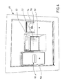
- Fig. 4 illustrates the interface panel 48
- Fig. 5 illustrates the box-shaped structure 16 before the interface panel is applied.
- An inside interface panel has been indicated with 62, associated to the housing 46. Also in this case, there may be provided a printing unit 64 (Fig. 6), and a control panel 66 to be activated by means of a further identification device 68, for example similar to the one provided on the interface panel 48.
- the user who needs to place an object into the night safe activates the identification device 56, such as by means of an electronic key, by means of a badge, or also by means of a barcode.
- the identification of the user generates an identification signal that is processed by the electronic card 44, which enables the opening/lifting of the shutter by means of the actuator 40.
- An upper end-of-stroke defining the shutter most-opened position has been indicated with 70.
- the pocket 20 can be reached from the outside and the user may insert the object, for example a purse or an envelope, such that the latter rests on a base wall 20b of the pocket.
- the object for example a purse or an envelope
- the reading axis of the first sensing device is interrupted, which is located near the pocket bottom, thereby a first signal is generated that is processed by the electronic card 44.
- the shutter is then automatically closed until it reaches an end-of-stroke 72 at an end-of-stroke sensor, a closing signal being thus generated.
- the end-of-stroke sensor is activated by the arm 34 that is integral to the shutter.
- a further end-of-stroke 74 may be associated to the shutter actuator.
- the motor 38 When the first signal is provided (corresponding to the object being in the pocket) and subsequently when the shutter is closed, and then when the closing signal is generated, the motor 38 is activated and controlled by means of the electronic card 44, the drum being caused to rotate by an angle which is equal to the distance between the front aperture 22 and the bottom aperture 24.
- the shutter When the first signal is not provided (corresponding to the object not being in the pocket), the shutter is automatically closed after a predetermined delay following aperture.
- the second sensing device which is capable of sensing that an obstacle is present (for example a user's hand), will cause the shutter to stop the closing movement, by means of a second signal, until the obstacle has been removed.
- the pocket 20 faces the bottom aperture 24, the object contained therein falls by gravity, thereby the reading axis of the third sensing device 31 will be interrupted, and a third signal will be thus generated that corresponds to the object having properly passed through the unloading duct to the inside of the night safe.
- the optional printing unit 60 issues a ticket comprising the data of the operation carried out.
- the data of each operation can be seen by means of the electronic card and queried or printed by means of the inner interface panel associated to the housing 46.
- the electronic card 44 comprises means, which can be preferably activated by means of the inside panel, for either testing or resetting the drum rotation between the loading position and the unloading position.
- Fig. 3 shows a possible embodiment of the electronic card 44 allowing the night safe to be adapted to the different installation needs, even after the night safe has been mounted.
- a reset device has been indicated with 76
- a power supply has been indicated with 77
- a drum motor power supply has been indicated with 78
- a shutter actuator power supply has been indicated with 79
- a serial port for optional connection to a PC has been indicated with 80
- an external printing unit power supply has been indicated with 81
- a serial port for optional connection to the external printing unit has been indicated with 82
- a badge reader has been indicated with 83
- a serial port for optional connection to an internal printing unit has been indicated with 84
- different inputs that can be adapted to detect and handle signals from those end-of-strokes being used, the drum motor and shutter actuator encoders, and the sensing devices have been indicated with 85.
- the provision of an electronic card and standardized housings allows the night safe to be adapted to the different installation requirements without having to drastically modifying the structure thereof, either before installation or in the case of an already mounted night safe.
- the sensing devices Due to the position and orientation of the sensing devices (particularly of the first one) the presence of any object can be detected independently from the thickness thereof (even of a single sheet).
- the other sensing devices allow safer operation, thus avoiding either accidents to the operator or malfunctioning because of improper unloading.
- sensing or identification devices may be used as a function of the technology to be applied.
Landscapes
- Business, Economics & Management (AREA)
- Finance (AREA)
- Operating, Guiding And Securing Of Roll- Type Closing Members (AREA)
Abstract
Description
- The object of the present invention is a night safe.
- The term "night safe" is known to mean a connecting device between the outside and either a safe or however a safe area, to which certain users may have access in order to introduce objects such as purses, envelopes or other things into the safe. A key is usually employed for access, in order to place the object into a drum that is arranged in a loading position. The drum is then caused to rotate until it reaches a position in which the object is unloaded into the safe.
- Known night saves have some drawbacks. In some cases, the step of inserting the object into the drum has not proved to be safe because the shutter has closed in spite of the presence of the user's hand. Furthermore, known night saves are not versatile and have fixed structure and functioning, which may not be substantially changed after the night safe has been assembled in position.
- Finally, currently available night saves do not allow for continuous and safe monitoring of the operations being carried out, hence they only provide limited safety.
- From what has been stated above, it emerges that a need is felt for a night safe that is versatile and reliable both for the user upon use and for the objects contained therein.
- The problem at the heart of the present invention is to provide a night safe which has such structural and functional characteristics as to meet said need, and that overcomes the mentioned drawbacks with reference to the
- This problem is solved by means of a night safe in accordance with claim 1.
- Further characteristics and the advantages of the night safe according to the invention will be understood from the description below of a preferred exemplary embodiment thereof, which is given by way of non-limiting illustration, with reference to the annexed figures, in which:
- Fig. 1 shows a schematic perspective view of a night safe according to the present invention;
- Fig. 2 shows a schematic side view of the night safe from Fig. 1;
- Fig. 3 shows a schematic plan view of an electronic card to be used in a night safe according to the present invention;
- Fig. 4 shows a schematic perspective view of a detail of the night safe from Fig. 1;
- Fig. 5 shows a schematic perspective view of a further detail of the night safe from Fig. 1;
- Fig. 6 and Fig. 7 show two schematic perspective views of two embodiments of a detail of the night safe from Fig. 1;
- Fig. 8 shows a schematic rear view of the night safe from Fig. 1.
- With reference to said figures, a night safe, i.e. a device adapted to receive objects such as purses, envelopes and the like from authorized staff and to transfer the latter in a protected area, for example a safe to be reached by means of an independent door has been generally indicated with 10. In several cases, the night safe is an interface between the outside of a building and the inside of the latter, particularly in the case of banks and the like.
- In accordance with a possible embodiment, a
drum 12 is rotatably mounted around ashaft 13 extending along anaxis 14, preferably arranged in a horizontal plane. - The
drum 12 is mounted within a box-shaped structure 16, for example comprising twoside shoulders 16a, afront wall 16b, arear wall 16c and abottom 16d. The ends of theshaft 13 extend through theside shoulders 16a of the box-shaped structure. - The
drum 14 has ahousing 18 for apocket 20 arranged according to a substantially radial direction of the drum. Preferably, thehousing 18 and thecorresponding pocket 20 have a substantially prismatic shape that is open on the outside of thedrum 12, in which sidewalls arranged perpendicular to the drum axis have been indicated with 20a, base walls substantially arranged in the direction of a drum radius have been indicated with 20b and a bottom of thepocket 20 has been indicated with 20c. Thehousing 18 andpocket 20 extend in width in the drum axial direction, in height along a direction which is tangential to the drum and in depth along a direction which is radial to the drum. Preferably, thepocket 20 has a greater extension in the axial direction rather than in the tangential direction relative to the drum in order to receive objects such as purses, envelopes and the like. - A front aperture has been indicated with 22 and a bottom aperture has been indicated with 24, which are provided in the
front wall 16b and thebottom 16d of the box-shaped structure 16, respectively. The two apertures have suitable shape and size to allow access to thepocket 20 inserted into thehousing 18. - The
pocket 20 has a size which is slightly smaller than thehousing 18, particularly in the direction tangential to the drum such as to form agap 26 preferably between thebase walls 20b of the pocket and the walls defining the housing. - In accordance with an embodiment of the invention, a
first sensing device 28 is directly mounted to the drum, between thepocket 20 andhousing 18, thus defining a reading axis arranged along the height extension of the pocket. In other words, the reading axis is arranged in the direction tangential to thedrum 12. Advantageously, thefirst sensing device 28 is located near thebottom 20c of thepocket 20. - Preferably, the
first sensing device 28 comprises a photocell in which afirst probe 28a is housed within thegap 26 by passing through one of thebase walls 20b and asecond probe 28b is housed within theopposite gap 26 by passing through theopposite base wall 20b. - In accordance with an embodiment of the invention, a
second sensing device 30 is directly mounted on a drum, between thepocket 20 andhousing 18, thus defining a reading axis arranged along the height extension of the pocket, substantially parallel to the first one. Therefore, also in this case, the reading axis is arranged in the direction tangential to thedrum 12. Advantageously, thesecond sensing device 30 is located near the opening of thepocket 20. - Such as for the
first sensing device 28, thesecond sensing device 30 preferably comprises a photocell in which afirst probe 30a is housed within thegap 26 by passing through one of thebase walls 20b and asecond probe 30b is housed within theopposite gap 26 by passing through theopposite base wall 20b. - A
third sensing device 31 is arranged on the box-shaped structure 16, at thebottom aperture 24. For example, thethird sensing device 31 comprises a photocell in which afirst probe 31a and asecond probe 31b are arranged on opposite sides of thebottom aperture 24. - A shutter which is rotatably mounted around the periphery of the
drum 12, at the opening of thepocket 20, has been indicated with 32. Anarm 34 integral with theshutter 32 extends through aslot 36 provided in aside shoulder 16. - A
motor 38 is operatively associated to theshaft 13 of thedrum 12 in order to cause the latter to rotate around theaxis 14 between at least one loading position and at least one unloading position. In the loading position thepocket 20 faces thefront aperture 22 whereas in the unloading position thepocket 20 faces thebottom aperture 24. - An
actuator 40 is operatively associated to theshutter 32, through thearm 34, in order to move the latter between an opening position and a closing position of thepocket 20. Theactuator 40 preferably comprises anendless screw 42 adapted to thrust the arm 3. During the descent, the shutter descends by gravity whereas theactuator 40 returns to the initial position. When either a hand or an obstacle is inserted, as will be described herein below, theactuator 40 being always in contact with the shutter stops by blocking the shutter descent. When the obstacle is removed, the actuator is operated again and the shutter is free to further descend to the closing position. - The
motor 38 is advantageously associated to an encoder and controlled by means of anelectronic card 44 being housed for example opposite to thefront aperture 22, at ahousing 46 being provided within the building that houses the night safe. - In accordance with a possible embodiment, the
actuator 40 is also advantageously associated to an encoder and controlled by means of theelectronic card 44. - The
motor 38 andactuator 40 define independent motor means for the drum and shutter. - An interface panel with the outside adapted to be fastened onto the box-
shaped structure 16 at thefront aperture 22 has been indicated with 48. - The
interface panel 48 comprises anaperture 50 facing thefront aperture 22 andshutter 32, when it is in the closing position. Advantageously, theaperture 50 is defined by tilted walls, at least one of which being provided withlighting 52. - A
further aperture 54 on theinterface panel 48 allows anidentification device 56, which is for example embodied by a key-, badge-, barcode-reader and the like to be housed therein. Theidentification device 56 is operatively associated to theelectronic card 44 controlling themotor 38 andactuator 40. - In accordance with a possible embodiment, the
interface panel 48 is provided with a stillfurther aperture 58 adapted to accommodate further devices, for example aprinting unit 60 being operatively associated to theelectronic card 44. Optionally, a lid, not shown, may close the stillfurther aperture 58, in the case where the use of additional devices is not provided. Fig. 4 illustrates theinterface panel 48, and Fig. 5 illustrates the box-shaped structure 16 before the interface panel is applied. - An inside interface panel has been indicated with 62, associated to the
housing 46. Also in this case, there may be provided a printing unit 64 (Fig. 6), and acontrol panel 66 to be activated by means of afurther identification device 68, for example similar to the one provided on theinterface panel 48. - The operation mode of the night safe described above will be described below.
- The user who needs to place an object into the night safe activates the
identification device 56, such as by means of an electronic key, by means of a badge, or also by means of a barcode. The identification of the user generates an identification signal that is processed by theelectronic card 44, which enables the opening/lifting of the shutter by means of theactuator 40. An upper end-of-stroke defining the shutter most-opened position has been indicated with 70. - Therefore, the
pocket 20 can be reached from the outside and the user may insert the object, for example a purse or an envelope, such that the latter rests on abase wall 20b of the pocket. When the object is inserted, independently from the height of the latter, the reading axis of the first sensing device is interrupted, which is located near the pocket bottom, thereby a first signal is generated that is processed by theelectronic card 44. - The shutter is then automatically closed until it reaches an end-of-
stroke 72 at an end-of-stroke sensor, a closing signal being thus generated. Preferably, the end-of-stroke sensor is activated by thearm 34 that is integral to the shutter. A further end-of-stroke 74 may be associated to the shutter actuator. - When the first signal is provided (corresponding to the object being in the pocket) and subsequently when the shutter is closed, and then when the closing signal is generated, the
motor 38 is activated and controlled by means of theelectronic card 44, the drum being caused to rotate by an angle which is equal to the distance between thefront aperture 22 and thebottom aperture 24. - When the first signal is not provided (corresponding to the object not being in the pocket), the shutter is automatically closed after a predetermined delay following aperture. In this instance, the second sensing device, which is capable of sensing that an obstacle is present (for example a user's hand), will cause the shutter to stop the closing movement, by means of a second signal, until the obstacle has been removed.
- When the
pocket 20 faces thebottom aperture 24, the object contained therein falls by gravity, thereby the reading axis of thethird sensing device 31 will be interrupted, and a third signal will be thus generated that corresponds to the object having properly passed through the unloading duct to the inside of the night safe. - If the deposit is properly carried out (user identification/the object is determined to be in the pocket/the object is determined to have been unloaded from the pocket), the
optional printing unit 60 issues a ticket comprising the data of the operation carried out. - However, the data of each operation can be seen by means of the electronic card and queried or printed by means of the inner interface panel associated to the
housing 46. - In accordance with a possible embodiment, the
electronic card 44 comprises means, which can be preferably activated by means of the inside panel, for either testing or resetting the drum rotation between the loading position and the unloading position. - Particularly, Fig. 3 shows a possible embodiment of the
electronic card 44 allowing the night safe to be adapted to the different installation needs, even after the night safe has been mounted. - For example, a reset device has been indicated with 76, a power supply has been indicated with 77, a drum motor power supply has been indicated with 78, a shutter actuator power supply has been indicated with 79, a serial port for optional connection to a PC has been indicated with 80, an external printing unit power supply has been indicated with 81, a serial port for optional connection to the external printing unit has been indicated with 82, a badge reader has been indicated with 83, a serial port for optional connection to an internal printing unit has been indicated with 84; finally, different inputs that can be adapted to detect and handle signals from those end-of-strokes being used, the drum motor and shutter actuator encoders, and the sensing devices have been indicated with 85.
- From what has been stated above, it should be appreciated that the need of increasing the safety, functionalities and versatility of the night safe is met by means of a night safe such as described above.
- Furthermore, the provision of an electronic card and standardized housings allows the night safe to be adapted to the different installation requirements without having to drastically modifying the structure thereof, either before installation or in the case of an already mounted night safe.
- The advantageous provision of means for independently moving the drum and shutter, both preferably comprising an encoder, allows enhancing the user safety, for example by introducing either a shutter free-closing movement control or a drum rotation self-calibration cycle. Moreover, optimum installation versatility is obtained by providing the encoder on the drum motor, which allows setting the drum rotation angle without structural restraints, as a function of the loading and unloading opening.
- Due to the position and orientation of the sensing devices (particularly of the first one) the presence of any object can be detected independently from the thickness thereof (even of a single sheet). The other sensing devices allow safer operation, thus avoiding either accidents to the operator or malfunctioning because of improper unloading.
- It is understood that variations and/or additions to what has been stated and illustrated above may be provided.
- For example, other types of sensing or identification devices may be used as a function of the technology to be applied.
- To the preferred embodiment of the night safe as described, those skilled in the art, aiming at satisfying contingent and specific needs, will be able to carry out several modifications, adjustments and replacements of elements with others functionally equivalent thereto, without however departing from the scope of the claims below.
Claims (21)
- A night safe comprising a box-shaped structure (16) suitable to house a drum (12) rotating around an axis (14) between a loading position and an unloading position and a shutter (32) to selectively allow access to a pocket (20) housed in the drum (12), characterized in that it comprises means for independently moving the drum (12) and shutter (32).
- The night safe according to claim 1, wherein said moving means comprise a motor (38) operatively associated to a shaft (13) of the drum (12), said motor (38) being associated to an encoder and controlled by means of an electronic card (44).
- The night safe according to claim 1 or 2, wherein said moving means comprise an actuator (40) operatively associated to the shutter (32), said actuator (40) being associated to an encoder and controlled by means of an electronic card (44).
- The night safe according to claim 3, wherein said moving means comprise an end-of-stroke (72) adapted to sense the closing of the shutter (32) and to allow the drum moving means to be activated as a function of the shutter closing condition.
- The night safe according to one of the preceding claims, comprising a first sensing device (28) directly mounted to the drum (12) near a bottom (20c) of a pocket (20) in order to accommodate objects to be introduced into the night safe.
- The night safe according to claim 5, wherein said first sensing device (28) is arranged between a pocket (20) and a housing (18) for said pocket, thus defining a reading axis arranged along the pocket height extension.
- The night safe according to claim 5 or 6, wherein said first sensing device (28) is arranged with the reading axis along the direction tangential to the drum (12).
- The night safe according to one of claims 5 to 7, wherein said first sensing device (28) comprises a photocell in which a first probe (28a) is housed in a gap (26) between said pocket (20) and a housing (18) for accommodating said pocket, by passing through one of the base walls (20b) of the pocket and a second probe (28b) is housed within an opposite gap (26) by passing through the opposite base wall (20b).
- The night safe according to any preceding claim, comprising a second sensing device (30) directly mounted to the drum (12) near the opening of a pocket (20) in order to accommodate objects to be introduced into the night safe.
- The night safe according to claim 9, wherein said second sensing device (30) is arranged between a pocket (20) and a housing (18) for said pocket, thus defining a reading axis arranged along the pocket height extension.
- The night safe according to claim 9 or 10, wherein said second sensing device (30) is arranged with the reading axis along the direction tangential to the drum (12).
- The night safe according to one of claims 9 to 11, wherein said second sensing device (30) comprises a photocell in which a first probe (30a) is housed in a gap (26) between said pocket (20) and a housing (18) for accommodating said pocket, by passing through one of the base walls (20b) of the pocket and a second probe (30b) is housed in an opposite gap (26) by passing through the opposite base wall (20b).
- The night safe according to any preceding claim, comprising a third sensing device (31) arranged on the box-shaped structure (16), at a bottom aperture (24) for unloading the objects introduced therein.
- The night safe according to claim 13, wherein the third sensing device (31) comprises a photocell in which a first probe (31a) and a second probe (31b) are situated on opposite sides of the bottom aperture (24).
- The night safe according to any preceding claim, comprising an interface panel (48) with the outside adapted to be fastened to the box-shaped structure (16) at a loading front aperture (22), said interface panel (48) comprising an aperture (50) facing the front aperture (22) and shutter (32).
- The night safe according to claim 15, wherein the interface panel (48) comprises the aperture (50) being defined by tilted walls, at least one of which is provided with lighting (52).
- The night safe according to claim 15 or 16, wherein a further aperture (54) of the interface panel (48) allows a identification device (56) to be housed, for example provided by means of a key-, badge-, barcode-reader and the like, said identification device (56) being operatively associated to an electronic card (44) for the control and monitoring of the means for independently moving the drum (12) and the shutter (32).
- The night safe according to claim 17, wherein the interface panel (48) is provided with a still further aperture (58) adapted to accommodate further devices, for example a printing unit (60) operatively associated to the electronic card (44).
- The night safe according to claim 18, wherein a lid (61) closes the still further aperture (58), in the case where the use of additional devices is not provided.
- The night safe according to any preceding claim, comprising an inside interface panel (62), associated to a housing (46) of the electronic card (44).
- The night safe according to claim 20, wherein said inside interface panel (62) comprises a printing unit (64) and/or a control panel (66) to be activated by means of a further identification device (68).
Applications Claiming Priority (1)
| Application Number | Priority Date | Filing Date | Title |
|---|---|---|---|
| ITMI20051226 ITMI20051226A1 (en) | 2005-06-29 | 2005-06-29 | CONTINUOUS CASH |
Publications (2)
| Publication Number | Publication Date |
|---|---|
| EP1739267A2 true EP1739267A2 (en) | 2007-01-03 |
| EP1739267A3 EP1739267A3 (en) | 2013-07-17 |
Family
ID=37074628
Family Applications (1)
| Application Number | Title | Priority Date | Filing Date |
|---|---|---|---|
| EP06425313.1A Withdrawn EP1739267A3 (en) | 2005-06-29 | 2006-05-09 | Night safe |
Country Status (2)
| Country | Link |
|---|---|
| EP (1) | EP1739267A3 (en) |
| IT (1) | ITMI20051226A1 (en) |
Cited By (1)
| Publication number | Priority date | Publication date | Assignee | Title |
|---|---|---|---|---|
| WO2008136031A1 (en) * | 2007-05-02 | 2008-11-13 | Riello Customade Robotic Dispenser S.P.A. | Device for handling small safe deposit boxes |
Family Cites Families (6)
| Publication number | Priority date | Publication date | Assignee | Title |
|---|---|---|---|---|
| US3897901A (en) * | 1974-06-10 | 1975-08-05 | Diebold Inc | Rotary depository construction |
| US4754126A (en) * | 1987-04-01 | 1988-06-28 | Ncr Corporation | Night depository method and apparatus |
| IES930391A2 (en) * | 1993-05-21 | 1994-08-24 | Rosspark Ltd | "Transfer apparatus" |
| FR2729431A1 (en) * | 1995-01-13 | 1996-07-19 | Consultant Materiel Ind | Security system for transferring funds through wall |
| ATE213047T1 (en) * | 1995-01-13 | 2002-02-15 | E A Rosengrens As | NIGHT SAFE OR SAFE, CONTROL UNIT AND INTERFACE CARD FOR THIS |
| AT500112B8 (en) * | 2003-06-20 | 2007-02-15 | Keba Ag | STORAGE MACHINE FOR OBJECTS |
-
2005
- 2005-06-29 IT ITMI20051226 patent/ITMI20051226A1/en unknown
-
2006
- 2006-05-09 EP EP06425313.1A patent/EP1739267A3/en not_active Withdrawn
Cited By (1)
| Publication number | Priority date | Publication date | Assignee | Title |
|---|---|---|---|---|
| WO2008136031A1 (en) * | 2007-05-02 | 2008-11-13 | Riello Customade Robotic Dispenser S.P.A. | Device for handling small safe deposit boxes |
Also Published As
| Publication number | Publication date |
|---|---|
| EP1739267A3 (en) | 2013-07-17 |
| ITMI20051226A1 (en) | 2006-12-30 |
Similar Documents
| Publication | Publication Date | Title |
|---|---|---|
| US11293630B2 (en) | Interactive tool storage system | |
| EP3369079B1 (en) | Detector housing assembly | |
| US20130340491A1 (en) | Lock Assembly | |
| US5931177A (en) | Valves | |
| CN114556725B (en) | Switch cabinet with switch cabinet door having door status sensor | |
| JP2008279017A (en) | Game machine | |
| CA2388009A1 (en) | A container for valuables | |
| CN114821901A (en) | Cabinet and method for detecting closing of cabinet door | |
| US11193313B2 (en) | Electromechanical closure having a rotary latch arrangement with an evaluatable door contact for controlling a display device such as an LED module | |
| US20060087272A1 (en) | Swing door opening/closing detection system | |
| JP2003010389A (en) | Slot medal sensor | |
| JP6885594B2 (en) | Control device and authentication system and manufacturing method of device | |
| JP4955318B2 (en) | Gift dispensing device | |
| KR100920501B1 (en) | Automatic shielding cover of fingerprint recognition unit and door lock system provided with the same | |
| JPH11328319A (en) | Banknote handling equipment | |
| JP5413147B2 (en) | Coin storage cassette and coin processor | |
| JP2006338280A (en) | Automatic vending machine | |
| JP2003115063A (en) | Non-contact token detector | |
| FI98647C (en) | Method and apparatus for preventing illegal movement and opening of money cartridge | |
| KR20080030327A (en) | Booth for financial automation equipment and its operation method | |
| JP6560318B2 (en) | Gift dispensing device | |
| JP2008300731A (en) | Structure of lid opening and holding member | |
| KR20030003852A (en) | Slot opening/closing device for vending machine | |
| ITMI992603A1 (en) | DEVICE AND PROCEDURE FOR THE CASE AND AUTOMATED DELIVERY OF MONEY AND VALUES IN ENVELOPES EQUIPPED WITH IDENTIFICATION ELEMENTS | |
| JP2012038016A (en) | Ic card reader/writer |
Legal Events
| Date | Code | Title | Description |
|---|---|---|---|
| PUAI | Public reference made under article 153(3) epc to a published international application that has entered the european phase |
Free format text: ORIGINAL CODE: 0009012 |
|
| AK | Designated contracting states |
Kind code of ref document: A2 Designated state(s): AT BE BG CH CY CZ DE DK EE ES FI FR GB GR HU IE IS IT LI LT LU LV MC NL PL PT RO SE SI SK TR |
|
| AX | Request for extension of the european patent |
Extension state: AL BA HR MK YU |
|
| PUAL | Search report despatched |
Free format text: ORIGINAL CODE: 0009013 |
|
| AK | Designated contracting states |
Kind code of ref document: A3 Designated state(s): AT BE BG CH CY CZ DE DK EE ES FI FR GB GR HU IE IS IT LI LT LU LV MC NL PL PT RO SE SI SK TR |
|
| AX | Request for extension of the european patent |
Extension state: AL BA HR MK YU |
|
| RIC1 | Information provided on ipc code assigned before grant |
Ipc: E05G 7/00 20060101AFI20130607BHEP |
|
| AKY | No designation fees paid | ||
| REG | Reference to a national code |
Ref country code: DE Ref legal event code: R108 |
|
| REG | Reference to a national code |
Ref country code: DE Ref legal event code: R108 Effective date: 20140326 |
|
| STAA | Information on the status of an ep patent application or granted ep patent |
Free format text: STATUS: THE APPLICATION IS DEEMED TO BE WITHDRAWN |
|
| 18D | Application deemed to be withdrawn |
Effective date: 20140118 |