EP1739245A1 - Log wall structure - Google Patents
Log wall structure Download PDFInfo
- Publication number
- EP1739245A1 EP1739245A1 EP06012477A EP06012477A EP1739245A1 EP 1739245 A1 EP1739245 A1 EP 1739245A1 EP 06012477 A EP06012477 A EP 06012477A EP 06012477 A EP06012477 A EP 06012477A EP 1739245 A1 EP1739245 A1 EP 1739245A1
- Authority
- EP
- European Patent Office
- Prior art keywords
- log
- wall structure
- structure according
- air
- insulation
- Prior art date
- Legal status (The legal status is an assumption and is not a legal conclusion. Google has not performed a legal analysis and makes no representation as to the accuracy of the status listed.)
- Granted
Links
Images
Classifications
-
- E—FIXED CONSTRUCTIONS
- E04—BUILDING
- E04B—GENERAL BUILDING CONSTRUCTIONS; WALLS, e.g. PARTITIONS; ROOFS; FLOORS; CEILINGS; INSULATION OR OTHER PROTECTION OF BUILDINGS
- E04B1/00—Constructions in general; Structures which are not restricted either to walls, e.g. partitions, or floors or ceilings or roofs
- E04B1/62—Insulation or other protection; Elements or use of specified material therefor
- E04B1/74—Heat, sound or noise insulation, absorption, or reflection; Other building methods affording favourable thermal or acoustical conditions, e.g. accumulating of heat within walls
- E04B1/76—Heat, sound or noise insulation, absorption, or reflection; Other building methods affording favourable thermal or acoustical conditions, e.g. accumulating of heat within walls specifically with respect to heat only
- E04B1/7675—Insulating linings for the interior face of exterior walls
-
- E—FIXED CONSTRUCTIONS
- E04—BUILDING
- E04B—GENERAL BUILDING CONSTRUCTIONS; WALLS, e.g. PARTITIONS; ROOFS; FLOORS; CEILINGS; INSULATION OR OTHER PROTECTION OF BUILDINGS
- E04B1/00—Constructions in general; Structures which are not restricted either to walls, e.g. partitions, or floors or ceilings or roofs
- E04B1/62—Insulation or other protection; Elements or use of specified material therefor
- E04B1/70—Drying or keeping dry, e.g. by air vents
- E04B1/7069—Drying or keeping dry, e.g. by air vents by ventilating
-
- E—FIXED CONSTRUCTIONS
- E04—BUILDING
- E04B—GENERAL BUILDING CONSTRUCTIONS; WALLS, e.g. PARTITIONS; ROOFS; FLOORS; CEILINGS; INSULATION OR OTHER PROTECTION OF BUILDINGS
- E04B2/00—Walls, e.g. partitions, for buildings; Wall construction with regard to insulation; Connections specially adapted to walls
- E04B2/56—Load-bearing walls of framework or pillarwork; Walls incorporating load-bearing elongated members
- E04B2/70—Load-bearing walls of framework or pillarwork; Walls incorporating load-bearing elongated members with elongated members of wood
- E04B2/701—Load-bearing walls of framework or pillarwork; Walls incorporating load-bearing elongated members with elongated members of wood with integrated supporting and obturation function
- E04B2/702—Load-bearing walls of framework or pillarwork; Walls incorporating load-bearing elongated members with elongated members of wood with integrated supporting and obturation function with longitudinal horizontal elements
Definitions
- the invention relates to a log wall structure defined in the preamble of Claim 1.
- a wall structure like this additionally includes a moisture permeable air barrier layer or vapour barrier to be fastened to a separate battening inside the additional insulation layer, and the inner wall surface itself.
- a log wall structure includes logs on top of each other.
- the logs to be used are preferably square logs but also round logs can be used.
- the structure also includes an insulation layer on the inner side of the log, and an inner wall surface covering the insulation layer. Additionally, the insulation layer may include a battening to which the inner wall surface has been fastened.
- the construction contains essentially vertical spaced air channels at the interface log-insulation, for ventilating the wall structure.
- the basic idea of the invention is a limited ventilation, that is, the air channels are not in contact with each other but, they clearly have a remarkable distance to each other. So, the log only is cold in the area of the air channels, and the heat insulation capacity of the log mainly remains unchanged.
- Air channels with appropriate spacing are capable of sufficiently ventilating the inner log surface and to remove the excess moisture from the entire area thereof.
- the distances between the air channels preferably are in the range of 10 to 60 cm, e.g., approximately 30 cm, the width of the area free from air channels being in the same order, because the width of the air channel preferably is just a few centimetres.
- a log wall structure according to the invention also can be realised using a totally or partially load-bearing battening, in other words, also so that the wall structure has a vertical frame, to which the log coating forming the outer surface has been fastened.
- log denotes a structure thicker than a board or panel structure, having a significant meaning for the heat insulation capacity of the entire wall.
- log thicknesses more than 40 to 50 mm are usable for the invention.
- the wall structure also contains connecting channels extending from the interface log-insulation to the outer side of the wall, connecting the air channels with the air space on the outer side of the wall. In this way, the moisture possibly condensing in the wall structure can escape from the structure via air channels and connecting channels.
- gravity ventilation operates such that, in the air channels, a vertical flow is created by the temperature of the air channels deviating from the air outside the wall structure.
- forced flow also can be used for intensifying the ventilation.
- the connecting channel is passing through the log.
- the channel can be easily machined directly into the log with, and no channel-forming structures are needed for it, like a tube, since the log itself acts as a supporting structure forming a free channel. If needed, the opening of the connecting channel can be covered with a grid or a net preventing birds or small animals from getting into the channels.
- the connecting channels it also is possible for the connecting channels to begin beneath the lowermost log from the outer space and/or to end up above the uppermost log in the outer space, thereupon not passing through the log.
- the structure forming the air channel preferably includes a longish water vapour permeable strip set against the log and/or the vertical battening for the insulation layer.
- This strip either alone or together with the log and/or battening surface, forms the air channel in question.
- the strip itself preferably is made of a water vapour permeable material. It also is possible to use some perforated, as such water vapour impermeable material.
- the material of the strip also is so soft and elastic that, notwithstanding the possible lowering and deformations of the logs, the air channel remains non-plugged and non-broken.
- a preferable material is, for example, cardboard.
- the longish strip includes flanges for fastening thereof to the log and/or the battening, and an intermediate part between the flanges, together with the mounting base, forming an air channel.
- the cross-sectional form of the intermediate part can be angular or curved. It is essential that it is separated from the mounting base of the strip.
- the flanges preferably extend over the entire length of the strip. Thus, in addition to acting as a fixing point, they prevent the channel from being clogged, for example, upon applying loose insulation material by blowing or spraying.
- the strip of material permeable for water vapour, tube or channel, no matter if having a closed or an open cross-section facing to the log, may have on square, triangle, round or whatsoever cross-section.
- the horizontal groove at the joint of two logs on top of each other preferably is coated with a water vapour permeable strip.
- the groove covered by the strip forms an intermediate channel interconnecting the adjoining air channels.
- the structure forming the air channel also can contain a longish groove which, together with the log surface, forms the air channel.
- the groove also can be made as a chamfer in the edge of the insulation plate to be mounted against the juncture between the log surface and the battening, the air channel thereby being formed together by the chamfer, the log surface and the battening.
- the sizes and numbers of the air, connecting and intermediate channels may vary depending on the situation and the need for ventilation.
- empiric observations as well as physical modelling can be utilised.
- the inventive log wall structure mainly has been developed for structures without water vapour barrier but nothing prevents using it also in structures provided with water vapour barrier, since moisture entering the structure is removed by the invention regardless of the direction in which the moisture enters.
- more or less breathing insulations may be used, like cellulose wool, glass wool, mineral wool, polyurethane, sawdust, other wood fibre insulations etc.
- a breathing windshield is used, like paper or cardboard, on which the vertical air channels then are mounted.
- the vapour barrier already mentioned or a water vapour permeable constructing cardboard may be used as an air barrier layer.
- the inventive log wall structure has remarkable advantages over prior art.
- providing the ventilation for the wall structure has been accomplished in a very simple way requiring only a few working steps and costs, which also is well applicable for do-it-yourself building.
- the strips and flaps forming the necessary air channels and intermediate channels may be present as a cardboard roll which is easy to handle and lightweight, from which they are cut to desired length. It also is possible to use sheets and strips of cardboard or other material already being provided with creases, so that in the mounting stage, the channel can easily be turned or bent to proper form.
- the simplicity and the cheapness of the structure are increased by the fact that the channels extend at the surface of the log, in other words, there is no need for machining forms in the surfaces of the logs, required by the structure. So, for the inventive structure, all existing log frames and those manufactured by the modern techniques and know-how are applicable. Depending on the structures only, at the upper and lower ends of the wall, channels extending through the log may be necessary.
- a log wall structure according to the invention also is very multipurpose.
- the solution according to the invention can be utilised both in a settling traditional log wall and a non-settling wall structure. Neither is the log profile critical, the logs may be both square and round logs.
- the most important feature required from the insulation is permeability for water vapour but, for the rest, insulations both inserted by blowing and board-like, may be used in the inventive log wall structure. So as to be suitable for each situation, the efficiency of the ventilation properly may be adjusted the by the size and number of the air channels, while considering the climate type in the region, the log and insulation thicknesses, and other physical properties, the conditions prevailing in the building, and other factors influencing to condensation of moisture and need for ventilation.
- a log wall structure according to the invention contains as the outermost layer a log 1.
- a log On the inner side of the log, there is an insulation layer 2 and an inner wall surface 3 covering it.
- the material of the insulation material is water vapour permeable so as to guarantee breathing of the structure.
- an insulation material for example, cellulose wool is used.
- a water vapour barrier can be used, if required by the insulations and other wall structures employed.
- the insulation layer also is provided with a battening 6.
- At the interface log-insulation there are essentially vertically mounted strips permeable for water vapour, set against the log and/or the battening. Together with their mounting base, the strips form essentially vertical air channels 4 at the interface in order to ventilate the structure.
- FIG. 2 In the cross-section of Fig. 2 also an embodiment is shown for connecting channels 5 connecting the air space 4 with the air space on the outer side of the wall. From the interface log-insulation, they pass to the outer side of the wall straight through the logs 1.
- free gravity ventilation is enabled in the channels.
- the function is based on the fact that, in the air channels 4 inside the wall structure, the air has a different the temperature than the air on the outer side of the wall structure.
- a vertical air flow is then created in the channels, effectively transporting away moisture possibly condensed in the structure.
- the alternative shown in Fig. 3 for the longish strip 7 belonging to the structure forming the air channel is provided with flanges 8 for fastening thereof to the log and/or to the vertical battening for the insulation layer. Fastening can be accomplished, for example, by rivets or by gluing.
- the strip also includes an intermediate part 9 remaining elevated from the mounting base and forming therewith an air channels free from insulation.
- the folds of the strip form a channel structure with triangular cross-section.
- the cross-section of the intermediate part 9 can be, for example, rectangular or curved.
- the intermediate part 9 can be a closed tube as such without flanges 8 or provided with them.
- the strip 7 is set in place before the insulation. So, an insulation material in bulk, to be mounted, for example, by blowing or injecting can be used without clogging the air channel 4.
- an insulation material in bulk, to be mounted for example, by blowing or injecting can be used without clogging the air channel 4.
- the strip 7 is water vapour permeable. It can be made of a material as such permeable to water vapour, for example, cardboard but, in principle, also some perforated material as such impermeable to water vapour can be used. When manufacturing of cardboard, the strips also are lightweight, and they can be made to a roll easy to handle and requiring little space, from which it's easy to cut them to desired length on site. Several strips may also be joined to a single sheet-like structure allowing several air channels to be realised at once.
- the embodiment according to the invention shown in Fig. 4 includes a water vapour permeable flap 11 covering the horizontal groove 10 at the joint of logs 1 on top of each other between the adjacent strips 7.
- the air channels remain under the strips 7.
- the flap 11 forms an intermediate channel connecting the air channels, free from insulation, remaining in Fig. 4 under the strip.
- the ventilation is intensified and, by including them in the structure, an entire network of horizontal and vertical ventilation channels can be formed.
- rivets also can be seen in the flanges of the right-hand strip used for fastening the strip to the logs 1.
- a board-like water vapour permeable insulation 12 is shown in Fig. 5, having a substantially vertical groove 13 at the surface to be mounted against the logs. Together with the log surface, the groove forms an air channel 4 required for ventilation.
- the groove also can be accomplished as a chamfer in the edge of the insulation board to be mounted against the joint between the log and the battening, the air channel then being formed together by the chamfer, the log and the battening.
Landscapes
- Engineering & Computer Science (AREA)
- Architecture (AREA)
- Physics & Mathematics (AREA)
- Electromagnetism (AREA)
- Civil Engineering (AREA)
- Structural Engineering (AREA)
- Acoustics & Sound (AREA)
- Building Environments (AREA)
- Load-Bearing And Curtain Walls (AREA)
Abstract
Description
- The invention relates to a log wall structure defined in the preamble of
Claim 1. - In comparison with traditional logs hewed from one tree, in the industrial production of log structures, several different log and log wall constructions are currently used, intended for improving the heat insulation capacity of the wall structure. Naturally, the insulation capacity is effected by the log thickness, and thick durable logs also can be manufactured by gluing from several parts. As is generally known, in addition to increasing the thickness of the log, the insulation capacity also can be improved by increasing the additional insulation in the wall structure. By using a water vapour permeable insulation layer inside the log, the heat insulation capacity of the structure can be improved without loosing its natural breathing. Usually, a wall structure like this additionally includes a moisture permeable air barrier layer or vapour barrier to be fastened to a separate battening inside the additional insulation layer, and the inner wall surface itself. Typically, as an inner surface of this kind a panel is used but, however, as the surface, also any board is suitable which, depending on the situation, can be painted or wallpapered. In addition to giving a high heat insulation capacity, the flexible use of different inner wall surfaces, also in log construction, is enabled by the log structure in question, as an alternative for traditional logs.
- In suitable conditions it is possible that, from the outside of the building, moisture penetrates into the insulation layer through the log joints, or moisture escaping from the inside of the building condensates on the log surface facing to the additional insulation. If a situation like this occurs in practice, the water remaining in the wall can give rise to mould and structural damages.
- By utilising the invention, the drawbacks mentioned above shall be eliminated.
- Particularly, it is an object of the invention to disclose a new kind of log wall structure, in which ventilation removing the moisture possibly condensing in the structure is realised in a very simple and advantageous way.
- The log wall structure according to the invention is characterised by what is presented in the claims.
- A log wall structure according to the invention includes logs on top of each other. The logs to be used are preferably square logs but also round logs can be used. The structure also includes an insulation layer on the inner side of the log, and an inner wall surface covering the insulation layer. Additionally, the insulation layer may include a battening to which the inner wall surface has been fastened. In accordance with the invention, the construction contains essentially vertical spaced air channels at the interface log-insulation, for ventilating the wall structure.
- The basic idea of the invention is a limited ventilation, that is, the air channels are not in contact with each other but, they clearly have a remarkable distance to each other. So, the log only is cold in the area of the air channels, and the heat insulation capacity of the log mainly remains unchanged. Air channels with appropriate spacing, however, are capable of sufficiently ventilating the inner log surface and to remove the excess moisture from the entire area thereof. Thus, the distances between the air channels preferably are in the range of 10 to 60 cm, e.g., approximately 30 cm, the width of the area free from air channels being in the same order, because the width of the air channel preferably is just a few centimetres.
- A log wall structure according to the invention also can be realised using a totally or partially load-bearing battening, in other words, also so that the wall structure has a vertical frame, to which the log coating forming the outer surface has been fastened. Thus, in the invention, log denotes a structure thicker than a board or panel structure, having a significant meaning for the heat insulation capacity of the entire wall. Thus, log thicknesses more than 40 to 50 mm are usable for the invention.
- Preferably, the wall structure also contains connecting channels extending from the interface log-insulation to the outer side of the wall, connecting the air channels with the air space on the outer side of the wall. In this way, the moisture possibly condensing in the wall structure can escape from the structure via air channels and connecting channels.
- Preferably, for allowing free gravity ventilation, there are connecting channels both in the upper and lower parts of the wall. In a solution like this, gravity ventilation operates such that, in the air channels, a vertical flow is created by the temperature of the air channels deviating from the air outside the wall structure. However, forced flow also can be used for intensifying the ventilation.
- Preferably, the connecting channel is passing through the log. The channel can be easily machined directly into the log with, and no channel-forming structures are needed for it, like a tube, since the log itself acts as a supporting structure forming a free channel. If needed, the opening of the connecting channel can be covered with a grid or a net preventing birds or small animals from getting into the channels. Naturally, it also is possible for the connecting channels to begin beneath the lowermost log from the outer space and/or to end up above the uppermost log in the outer space, thereupon not passing through the log.
- The structure forming the air channel preferably includes a longish water vapour permeable strip set against the log and/or the vertical battening for the insulation layer. This strip, either alone or together with the log and/or battening surface, forms the air channel in question. The strip itself preferably is made of a water vapour permeable material. It also is possible to use some perforated, as such water vapour impermeable material. Preferably, the material of the strip also is so soft and elastic that, notwithstanding the possible lowering and deformations of the logs, the air channel remains non-plugged and non-broken. A preferable material is, for example, cardboard. Several strips forming an air channel also may be connected to a single board-like structure.
- Preferably, the longish strip includes flanges for fastening thereof to the log and/or the battening, and an intermediate part between the flanges, together with the mounting base, forming an air channel. The cross-sectional form of the intermediate part can be angular or curved. It is essential that it is separated from the mounting base of the strip. The flanges preferably extend over the entire length of the strip. Thus, in addition to acting as a fixing point, they prevent the channel from being clogged, for example, upon applying loose insulation material by blowing or spraying.
- The strip of material permeable for water vapour, tube or channel, no matter if having a closed or an open cross-section facing to the log, may have on square, triangle, round or whatsoever cross-section.
- Furthermore, in a log wall structure according to the invention, between adjacent air channels, the horizontal groove at the joint of two logs on top of each other preferably is coated with a water vapour permeable strip. Thus, the groove covered by the strip forms an intermediate channel interconnecting the adjoining air channels. In this way, by arranging several intermediate channels in the structure, a network of horizontal and vertical ventilation channels may be provided.
- At the surface of the board-like insulation to be mounted against the log surface, the structure forming the air channel also can contain a longish groove which, together with the log surface, forms the air channel. The groove also can be made as a chamfer in the edge of the insulation plate to be mounted against the juncture between the log surface and the battening, the air channel thereby being formed together by the chamfer, the log surface and the battening.
- In a log wall structure according to the invention, the sizes and numbers of the air, connecting and intermediate channels may vary depending on the situation and the need for ventilation. When estimating the need for ventilation, empiric observations as well as physical modelling can be utilised.
- The inventive log wall structure mainly has been developed for structures without water vapour barrier but nothing prevents using it also in structures provided with water vapour barrier, since moisture entering the structure is removed by the invention regardless of the direction in which the moisture enters. Thus, in the structure according to the invention, more or less breathing insulations may be used, like cellulose wool, glass wool, mineral wool, polyurethane, sawdust, other wood fibre insulations etc. It also is possible that, on the inner surface of the log, a breathing windshield is used, like paper or cardboard, on which the vertical air channels then are mounted. Likewise, on top of the insulation, on the inner side of the structure, the vapour barrier already mentioned or a water vapour permeable constructing cardboard may be used as an air barrier layer.
- The inventive log wall structure has remarkable advantages over prior art. In the invention, providing the ventilation for the wall structure has been accomplished in a very simple way requiring only a few working steps and costs, which also is well applicable for do-it-yourself building. The strips and flaps forming the necessary air channels and intermediate channels may be present as a cardboard roll which is easy to handle and lightweight, from which they are cut to desired length. It also is possible to use sheets and strips of cardboard or other material already being provided with creases, so that in the mounting stage, the channel can easily be turned or bent to proper form. Additionally, the simplicity and the cheapness of the structure are increased by the fact that the channels extend at the surface of the log, in other words, there is no need for machining forms in the surfaces of the logs, required by the structure. So, for the inventive structure, all existing log frames and those manufactured by the modern techniques and know-how are applicable. Depending on the structures only, at the upper and lower ends of the wall, channels extending through the log may be necessary.
- A log wall structure according to the invention also is very multipurpose. The solution according to the invention can be utilised both in a settling traditional log wall and a non-settling wall structure. Neither is the log profile critical, the logs may be both square and round logs. In a structure without vapour barrier, the most important feature required from the insulation is permeability for water vapour but, for the rest, insulations both inserted by blowing and board-like, may be used in the inventive log wall structure. So as to be suitable for each situation, the efficiency of the ventilation properly may be adjusted the by the size and number of the air channels, while considering the climate type in the region, the log and insulation thicknesses, and other physical properties, the conditions prevailing in the building, and other factors influencing to condensation of moisture and need for ventilation.
- In the following, the invention is described in detail by means of embodiments, referring to the attached drawings, in which
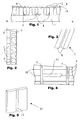
- Fig. 1 shows a horizontal cross-section of a log wall structure according to the invention, as seen from above or below,
- Fig. 2 shows a vertical cross-section of a log wall structure according to the invention, seen in the direction of the wall,
- Fig. 3 shows an alternative for a longish strip belonging to a structure forming the air channel,
- Fig. 4 shows a vertical cross-section of a log wall structure according to the invention at the interface log-insulation, in the longitudinal direction of the wall, as seen from the side, and
- Fig. 5 shows a board-like insulation belonging to a log wall structure according to the invention.
- A log wall structure according to the invention contains as the outermost layer a
log 1. On the inner side of the log, there is aninsulation layer 2 and aninner wall surface 3 covering it. The material of the insulation material is water vapour permeable so as to guarantee breathing of the structure. As such an insulation material, for example, cellulose wool is used. On top of the insulation, that is, under theinner wall surface 3, there is anair barrier layer 14 permeable to moisture in this embodiment. Instead, also a water vapour barrier can be used, if required by the insulations and other wall structures employed. For maintaining the insulation in position and fastening the inner wall, the insulation layer also is provided with abattening 6. At the interface log-insulation, there are essentially vertically mounted strips permeable for water vapour, set against the log and/or the battening. Together with their mounting base, the strips form essentiallyvertical air channels 4 at the interface in order to ventilate the structure. - In the cross-section of Fig. 2 also an embodiment is shown for connecting
channels 5 connecting theair space 4 with the air space on the outer side of the wall. From the interface log-insulation, they pass to the outer side of the wall straight through thelogs 1. By using a solution according to the figure having connecting channels both in the upper and the lower parts of the wall, free gravity ventilation is enabled in the channels. The function is based on the fact that, in theair channels 4 inside the wall structure, the air has a different the temperature than the air on the outer side of the wall structure. By the gravity, a vertical air flow is then created in the channels, effectively transporting away moisture possibly condensed in the structure. - The alternative shown in Fig. 3 for the
longish strip 7 belonging to the structure forming the air channel is provided withflanges 8 for fastening thereof to the log and/or to the vertical battening for the insulation layer. Fastening can be accomplished, for example, by rivets or by gluing. The strip also includes anintermediate part 9 remaining elevated from the mounting base and forming therewith an air channels free from insulation. In the figure, a simple solution is shown, in which the folds of the strip form a channel structure with triangular cross-section. Other forms also are possible, the cross-section of theintermediate part 9 can be, for example, rectangular or curved. In the same way, theintermediate part 9 can be a closed tube as such withoutflanges 8 or provided with them. Thestrip 7 is set in place before the insulation. So, an insulation material in bulk, to be mounted, for example, by blowing or injecting can be used without clogging theair channel 4. For the flanges, it is not necessary to be as long as the entire strip but, by using strips with full length, the channels are more effectively protected against clogging. - The
strip 7 is water vapour permeable. It can be made of a material as such permeable to water vapour, for example, cardboard but, in principle, also some perforated material as such impermeable to water vapour can be used. When manufacturing of cardboard, the strips also are lightweight, and they can be made to a roll easy to handle and requiring little space, from which it's easy to cut them to desired length on site. Several strips may also be joined to a single sheet-like structure allowing several air channels to be realised at once. - The embodiment according to the invention shown in Fig. 4 includes a water vapour
permeable flap 11 covering thehorizontal groove 10 at the joint oflogs 1 on top of each other between the adjacent strips 7. In the figure, for the sake of exemplification, it only is drawn for a part of the distance. In Fig. 4, the air channels remain under thestrips 7. Together with the groove at the joint between the logs, theflap 11 forms an intermediate channel connecting the air channels, free from insulation, remaining in Fig. 4 under the strip. By the intermediate channels, the ventilation is intensified and, by including them in the structure, an entire network of horizontal and vertical ventilation channels can be formed. In the figure, rivets also can be seen in the flanges of the right-hand strip used for fastening the strip to thelogs 1. - As an alternative for the
insulation layer 4, a board-like water vapourpermeable insulation 12 is shown in Fig. 5, having a substantially vertical groove 13 at the surface to be mounted against the logs. Together with the log surface, the groove forms anair channel 4 required for ventilation. The groove also can be accomplished as a chamfer in the edge of the insulation board to be mounted against the joint between the log and the battening, the air channel then being formed together by the chamfer, the log and the battening. - The invention is not limited to the embodiments disclosed above but, several modifications are possible within the scope of the inventive idea.
Claims (11)
- A log wall structure including a log (1), an insulation layer (2) on the inner side of the log, and an inner wall surface covering the insulation layer, characterised in that the interface log-insulation contains substantially vertical spaced air channels (4) for ventilating the wall structure.
- A log wall structure according to Claim 1, characterised in that the structure includes connecting channels (5) extending from the interface between the log (1) and the insulation (2) to the outer side of the wall, allowing the air channels (4) to communicate with the air space on the outer side of the wall structure.
- A log wall structure according to Claim 2, characterised in that there are connecting channels (5) both in the upper and the lower parts of the wall in order to enable free gravity ventilation.
- A log wall structure according to Claim 2 or 3, characterised in that the connecting channel passes through the log (1).
- A log wall structure according to Claim 1, characterised in that the structure forming the air channel contains a longish water vapour permeable strip (7), on the side of the log open or closed, mounted against the log (1) and/or the vertical battening of the insulation layer.
- A log wall structure according to Claim 5, characterised in that the strip includes flanges (8) for fastening it to the log and/or to the battening of the insulation layer, as well as an intermediate part (9) between the flanges elevated from the mounting base, forming an air channel together with the mounting base.
- A log wall structure according to any of the claims 1 to 6, characterised in that the substantially horizontal groove (10) at the joint of two logs on top of each other, over the distance between the adjoining air channels, is covered by a water vapour permeable flap (11) in order to form an intermediate channel connecting the air channels.
- A log wall structure according to Claim 1, characterised in that, at the surface of the board-like insulation (12) to be mounted against the log surface, the structure forming the air channel (4) includes a longish groove (13).
- A log wall structure according to any of the claims 1 to 8, characterised in that the vertical air channels are spaced from each other 10 to 60, preferably 20 to 40, for example, approximately 30 cm.
- A log wall structure according to any of the claims 1 to 9, characterised in that, between the air channels, there is a region free from air channels, having a multiple width, for example, 3 to 30 fold compared to the width of a single air channel.
- A log wall structure according to any of the claims 1 to 10, characterised in that, on top of the insulation layer (2), depending on the insulation used, an air barrier layer (14) or a vapour barrier is to be provided.
Applications Claiming Priority (1)
| Application Number | Priority Date | Filing Date | Title |
|---|---|---|---|
| FI20050664A FI20050664A0 (en) | 2005-06-20 | 2005-06-20 | Log Wall construction |
Publications (2)
| Publication Number | Publication Date |
|---|---|
| EP1739245A1 true EP1739245A1 (en) | 2007-01-03 |
| EP1739245B1 EP1739245B1 (en) | 2018-08-08 |
Family
ID=34778379
Family Applications (1)
| Application Number | Title | Priority Date | Filing Date |
|---|---|---|---|
| EP06012477.3A Expired - Lifetime EP1739245B1 (en) | 2005-06-20 | 2006-06-19 | Log wall structure |
Country Status (2)
| Country | Link |
|---|---|
| EP (1) | EP1739245B1 (en) |
| FI (1) | FI20050664A0 (en) |
Citations (5)
| Publication number | Priority date | Publication date | Assignee | Title |
|---|---|---|---|---|
| US2645824A (en) * | 1949-09-13 | 1953-07-21 | Edwin J Titsworth | Ventilated wall |
| DE3217072A1 (en) * | 1982-05-06 | 1983-11-10 | Gotthard 8359 Ortenburg Sonnleitner | Wooden-log cabin |
| DE3625405A1 (en) * | 1986-07-26 | 1988-02-04 | Hubert Fritz | Process for producing insulated walls of wooden houses |
| US4815250A (en) * | 1982-04-26 | 1989-03-28 | Mulford Cass E | Method of constructing a rafter |
| FR2847604A1 (en) * | 2002-11-22 | 2004-05-28 | Andre Allais | Wooden frontage wall corners connecting method for building e.g. country cottage, involves assembling to form exterior walls, where reinforcement of corners present complementary profile of projecting exterior ends of beams |
-
2005
- 2005-06-20 FI FI20050664A patent/FI20050664A0/en not_active Application Discontinuation
-
2006
- 2006-06-19 EP EP06012477.3A patent/EP1739245B1/en not_active Expired - Lifetime
Patent Citations (5)
| Publication number | Priority date | Publication date | Assignee | Title |
|---|---|---|---|---|
| US2645824A (en) * | 1949-09-13 | 1953-07-21 | Edwin J Titsworth | Ventilated wall |
| US4815250A (en) * | 1982-04-26 | 1989-03-28 | Mulford Cass E | Method of constructing a rafter |
| DE3217072A1 (en) * | 1982-05-06 | 1983-11-10 | Gotthard 8359 Ortenburg Sonnleitner | Wooden-log cabin |
| DE3625405A1 (en) * | 1986-07-26 | 1988-02-04 | Hubert Fritz | Process for producing insulated walls of wooden houses |
| FR2847604A1 (en) * | 2002-11-22 | 2004-05-28 | Andre Allais | Wooden frontage wall corners connecting method for building e.g. country cottage, involves assembling to form exterior walls, where reinforcement of corners present complementary profile of projecting exterior ends of beams |
Also Published As
| Publication number | Publication date |
|---|---|
| FI20050664A0 (en) | 2005-06-20 |
| EP1739245B1 (en) | 2018-08-08 |
Similar Documents
| Publication | Publication Date | Title |
|---|---|---|
| US6938383B2 (en) | Vented furring strip | |
| US5167579A (en) | Roof vent of synthetic fiber matting | |
| US7302776B2 (en) | Baffled attic vent | |
| US4977714A (en) | Roof ventilation baffle | |
| US6913530B2 (en) | Precipitation resistant ridge vent | |
| US7921619B2 (en) | Insulation batt having integral baffle vent | |
| US20140179220A1 (en) | Contoured Mesh Ridge Vents | |
| US20060079173A1 (en) | Roof ridge vent having honeycomb or like ventilation material | |
| US10196823B2 (en) | Roof ridge vent | |
| AU701980B2 (en) | Fascia vent | |
| US20230358051A1 (en) | Contoured mesh ridge vents | |
| US20060116069A1 (en) | Baffle-vent for S-tile ridge | |
| US8931215B1 (en) | Attic stairway insulator assembly | |
| US20100132288A1 (en) | Top Sided Vented Trim for Exterior Cladding System | |
| EP1739245B1 (en) | Log wall structure | |
| CN209538561U (en) | A kind of wall thermal insulating hydrofuge air exchange system | |
| EP0581025B1 (en) | Thermal insulation for sloping roofs | |
| GB2288227A (en) | Roof ventilation device | |
| GB2070662A (en) | Ventilation for insulated roof spaces | |
| CN110177979A (en) | Ridge ventilator | |
| JPS5752734A (en) | Ventilating structure for garret | |
| AU2024200878A1 (en) | A panel for roof ventilation | |
| DE3806157A1 (en) | Heat-exchanging ventilation wall system | |
| CA2611247C (en) | Insulation batt having integral baffle vent | |
| CA2199392C (en) | Fascia vent |
Legal Events
| Date | Code | Title | Description |
|---|---|---|---|
| PUAI | Public reference made under article 153(3) epc to a published international application that has entered the european phase |
Free format text: ORIGINAL CODE: 0009012 |
|
| AK | Designated contracting states |
Kind code of ref document: A1 Designated state(s): AT BE BG CH CY CZ DE DK EE ES FI FR GB GR HU IE IS IT LI LT LU LV MC NL PL PT RO SE SI SK TR |
|
| AX | Request for extension of the european patent |
Extension state: AL BA HR MK YU |
|
| 17P | Request for examination filed |
Effective date: 20070627 |
|
| AKX | Designation fees paid |
Designated state(s): AT BE BG CH CY CZ DE DK EE ES FI FR GB GR HU IE IS IT LI LT LU LV MC NL PL PT RO SE SI SK TR |
|
| STAA | Information on the status of an ep patent application or granted ep patent |
Free format text: STATUS: EXAMINATION IS IN PROGRESS |
|
| 17Q | First examination report despatched |
Effective date: 20161031 |
|
| REG | Reference to a national code |
Ref country code: DE Ref legal event code: R079 Ref document number: 602006056009 Country of ref document: DE Free format text: PREVIOUS MAIN CLASS: E04B0002700000 Ipc: E04B0001700000 |
|
| GRAP | Despatch of communication of intention to grant a patent |
Free format text: ORIGINAL CODE: EPIDOSNIGR1 |
|
| STAA | Information on the status of an ep patent application or granted ep patent |
Free format text: STATUS: GRANT OF PATENT IS INTENDED |
|
| RIC1 | Information provided on ipc code assigned before grant |
Ipc: E04B 1/76 20060101ALI20180129BHEP Ipc: E04B 1/70 20060101AFI20180129BHEP Ipc: E04B 2/70 20060101ALI20180129BHEP |
|
| INTG | Intention to grant announced |
Effective date: 20180223 |
|
| GRAS | Grant fee paid |
Free format text: ORIGINAL CODE: EPIDOSNIGR3 |
|
| GRAA | (expected) grant |
Free format text: ORIGINAL CODE: 0009210 |
|
| STAA | Information on the status of an ep patent application or granted ep patent |
Free format text: STATUS: THE PATENT HAS BEEN GRANTED |
|
| AK | Designated contracting states |
Kind code of ref document: B1 Designated state(s): AT BE BG CH CY CZ DE DK EE ES FI FR GB GR HU IE IS IT LI LT LU LV MC NL PL PT RO SE SI SK TR |
|
| REG | Reference to a national code |
Ref country code: GB Ref legal event code: FG4D |
|
| REG | Reference to a national code |
Ref country code: CH Ref legal event code: EP Ref country code: AT Ref legal event code: REF Ref document number: 1027190 Country of ref document: AT Kind code of ref document: T Effective date: 20180815 |
|
| REG | Reference to a national code |
Ref country code: IE Ref legal event code: FG4D |
|
| REG | Reference to a national code |
Ref country code: DE Ref legal event code: R096 Ref document number: 602006056009 Country of ref document: DE |
|
| REG | Reference to a national code |
Ref country code: SE Ref legal event code: TRGR |
|
| REG | Reference to a national code |
Ref country code: NL Ref legal event code: MP Effective date: 20180808 |
|
| REG | Reference to a national code |
Ref country code: LT Ref legal event code: MG4D |
|
| REG | Reference to a national code |
Ref country code: AT Ref legal event code: MK05 Ref document number: 1027190 Country of ref document: AT Kind code of ref document: T Effective date: 20180808 |
|
| PG25 | Lapsed in a contracting state [announced via postgrant information from national office to epo] |
Ref country code: GR Free format text: LAPSE BECAUSE OF FAILURE TO SUBMIT A TRANSLATION OF THE DESCRIPTION OR TO PAY THE FEE WITHIN THE PRESCRIBED TIME-LIMIT Effective date: 20181109 Ref country code: AT Free format text: LAPSE BECAUSE OF FAILURE TO SUBMIT A TRANSLATION OF THE DESCRIPTION OR TO PAY THE FEE WITHIN THE PRESCRIBED TIME-LIMIT Effective date: 20180808 Ref country code: NL Free format text: LAPSE BECAUSE OF FAILURE TO SUBMIT A TRANSLATION OF THE DESCRIPTION OR TO PAY THE FEE WITHIN THE PRESCRIBED TIME-LIMIT Effective date: 20180808 Ref country code: BG Free format text: LAPSE BECAUSE OF FAILURE TO SUBMIT A TRANSLATION OF THE DESCRIPTION OR TO PAY THE FEE WITHIN THE PRESCRIBED TIME-LIMIT Effective date: 20181108 Ref country code: IS Free format text: LAPSE BECAUSE OF FAILURE TO SUBMIT A TRANSLATION OF THE DESCRIPTION OR TO PAY THE FEE WITHIN THE PRESCRIBED TIME-LIMIT Effective date: 20181208 Ref country code: PL Free format text: LAPSE BECAUSE OF FAILURE TO SUBMIT A TRANSLATION OF THE DESCRIPTION OR TO PAY THE FEE WITHIN THE PRESCRIBED TIME-LIMIT Effective date: 20180808 Ref country code: LT Free format text: LAPSE BECAUSE OF FAILURE TO SUBMIT A TRANSLATION OF THE DESCRIPTION OR TO PAY THE FEE WITHIN THE PRESCRIBED TIME-LIMIT Effective date: 20180808 |
|
| PG25 | Lapsed in a contracting state [announced via postgrant information from national office to epo] |
Ref country code: LV Free format text: LAPSE BECAUSE OF FAILURE TO SUBMIT A TRANSLATION OF THE DESCRIPTION OR TO PAY THE FEE WITHIN THE PRESCRIBED TIME-LIMIT Effective date: 20180808 Ref country code: ES Free format text: LAPSE BECAUSE OF FAILURE TO SUBMIT A TRANSLATION OF THE DESCRIPTION OR TO PAY THE FEE WITHIN THE PRESCRIBED TIME-LIMIT Effective date: 20180808 |
|
| PG25 | Lapsed in a contracting state [announced via postgrant information from national office to epo] |
Ref country code: CZ Free format text: LAPSE BECAUSE OF FAILURE TO SUBMIT A TRANSLATION OF THE DESCRIPTION OR TO PAY THE FEE WITHIN THE PRESCRIBED TIME-LIMIT Effective date: 20180808 Ref country code: RO Free format text: LAPSE BECAUSE OF FAILURE TO SUBMIT A TRANSLATION OF THE DESCRIPTION OR TO PAY THE FEE WITHIN THE PRESCRIBED TIME-LIMIT Effective date: 20180808 Ref country code: EE Free format text: LAPSE BECAUSE OF FAILURE TO SUBMIT A TRANSLATION OF THE DESCRIPTION OR TO PAY THE FEE WITHIN THE PRESCRIBED TIME-LIMIT Effective date: 20180808 Ref country code: IT Free format text: LAPSE BECAUSE OF FAILURE TO SUBMIT A TRANSLATION OF THE DESCRIPTION OR TO PAY THE FEE WITHIN THE PRESCRIBED TIME-LIMIT Effective date: 20180808 |
|
| REG | Reference to a national code |
Ref country code: DE Ref legal event code: R097 Ref document number: 602006056009 Country of ref document: DE |
|
| PG25 | Lapsed in a contracting state [announced via postgrant information from national office to epo] |
Ref country code: DK Free format text: LAPSE BECAUSE OF FAILURE TO SUBMIT A TRANSLATION OF THE DESCRIPTION OR TO PAY THE FEE WITHIN THE PRESCRIBED TIME-LIMIT Effective date: 20180808 Ref country code: SK Free format text: LAPSE BECAUSE OF FAILURE TO SUBMIT A TRANSLATION OF THE DESCRIPTION OR TO PAY THE FEE WITHIN THE PRESCRIBED TIME-LIMIT Effective date: 20180808 |
|
| PLBE | No opposition filed within time limit |
Free format text: ORIGINAL CODE: 0009261 |
|
| STAA | Information on the status of an ep patent application or granted ep patent |
Free format text: STATUS: NO OPPOSITION FILED WITHIN TIME LIMIT |
|
| 26N | No opposition filed |
Effective date: 20190509 |
|
| PG25 | Lapsed in a contracting state [announced via postgrant information from national office to epo] |
Ref country code: SI Free format text: LAPSE BECAUSE OF FAILURE TO SUBMIT A TRANSLATION OF THE DESCRIPTION OR TO PAY THE FEE WITHIN THE PRESCRIBED TIME-LIMIT Effective date: 20180808 |
|
| PG25 | Lapsed in a contracting state [announced via postgrant information from national office to epo] |
Ref country code: MC Free format text: LAPSE BECAUSE OF FAILURE TO SUBMIT A TRANSLATION OF THE DESCRIPTION OR TO PAY THE FEE WITHIN THE PRESCRIBED TIME-LIMIT Effective date: 20180808 |
|
| REG | Reference to a national code |
Ref country code: CH Ref legal event code: PL |
|
| GBPC | Gb: european patent ceased through non-payment of renewal fee |
Effective date: 20190619 |
|
| REG | Reference to a national code |
Ref country code: BE Ref legal event code: MM Effective date: 20190630 |
|
| PG25 | Lapsed in a contracting state [announced via postgrant information from national office to epo] |
Ref country code: TR Free format text: LAPSE BECAUSE OF FAILURE TO SUBMIT A TRANSLATION OF THE DESCRIPTION OR TO PAY THE FEE WITHIN THE PRESCRIBED TIME-LIMIT Effective date: 20180808 |
|
| PG25 | Lapsed in a contracting state [announced via postgrant information from national office to epo] |
Ref country code: IE Free format text: LAPSE BECAUSE OF NON-PAYMENT OF DUE FEES Effective date: 20190619 Ref country code: GB Free format text: LAPSE BECAUSE OF NON-PAYMENT OF DUE FEES Effective date: 20190619 |
|
| PG25 | Lapsed in a contracting state [announced via postgrant information from national office to epo] |
Ref country code: CH Free format text: LAPSE BECAUSE OF NON-PAYMENT OF DUE FEES Effective date: 20190630 Ref country code: LI Free format text: LAPSE BECAUSE OF NON-PAYMENT OF DUE FEES Effective date: 20190630 Ref country code: LU Free format text: LAPSE BECAUSE OF NON-PAYMENT OF DUE FEES Effective date: 20190619 Ref country code: BE Free format text: LAPSE BECAUSE OF NON-PAYMENT OF DUE FEES Effective date: 20190630 |
|
| PG25 | Lapsed in a contracting state [announced via postgrant information from national office to epo] |
Ref country code: PT Free format text: LAPSE BECAUSE OF FAILURE TO SUBMIT A TRANSLATION OF THE DESCRIPTION OR TO PAY THE FEE WITHIN THE PRESCRIBED TIME-LIMIT Effective date: 20181208 |
|
| PG25 | Lapsed in a contracting state [announced via postgrant information from national office to epo] |
Ref country code: CY Free format text: LAPSE BECAUSE OF FAILURE TO SUBMIT A TRANSLATION OF THE DESCRIPTION OR TO PAY THE FEE WITHIN THE PRESCRIBED TIME-LIMIT Effective date: 20180808 |
|
| PG25 | Lapsed in a contracting state [announced via postgrant information from national office to epo] |
Ref country code: HU Free format text: LAPSE BECAUSE OF FAILURE TO SUBMIT A TRANSLATION OF THE DESCRIPTION OR TO PAY THE FEE WITHIN THE PRESCRIBED TIME-LIMIT; INVALID AB INITIO Effective date: 20060619 |
|
| PGFP | Annual fee paid to national office [announced via postgrant information from national office to epo] |
Ref country code: SE Payment date: 20220623 Year of fee payment: 17 Ref country code: DE Payment date: 20220621 Year of fee payment: 17 |
|
| PGFP | Annual fee paid to national office [announced via postgrant information from national office to epo] |
Ref country code: FR Payment date: 20220614 Year of fee payment: 17 |
|
| REG | Reference to a national code |
Ref country code: DE Ref legal event code: R119 Ref document number: 602006056009 Country of ref document: DE |
|
| REG | Reference to a national code |
Ref country code: SE Ref legal event code: EUG |
|
| PG25 | Lapsed in a contracting state [announced via postgrant information from national office to epo] |
Ref country code: DE Free format text: LAPSE BECAUSE OF NON-PAYMENT OF DUE FEES Effective date: 20240103 |
|
| PG25 | Lapsed in a contracting state [announced via postgrant information from national office to epo] |
Ref country code: SE Free format text: LAPSE BECAUSE OF NON-PAYMENT OF DUE FEES Effective date: 20230620 Ref country code: FR Free format text: LAPSE BECAUSE OF NON-PAYMENT OF DUE FEES Effective date: 20230630 |
|
| PGFP | Annual fee paid to national office [announced via postgrant information from national office to epo] |
Ref country code: FI Payment date: 20240625 Year of fee payment: 19 |
|
| PG25 | Lapsed in a contracting state [announced via postgrant information from national office to epo] |
Ref country code: FI Free format text: LAPSE BECAUSE OF NON-PAYMENT OF DUE FEES Effective date: 20250619 |