EP1738946A1 - Control device for opening and closing open top bodies in industrial vehicles - Google Patents
Control device for opening and closing open top bodies in industrial vehicles Download PDFInfo
- Publication number
- EP1738946A1 EP1738946A1 EP05105886A EP05105886A EP1738946A1 EP 1738946 A1 EP1738946 A1 EP 1738946A1 EP 05105886 A EP05105886 A EP 05105886A EP 05105886 A EP05105886 A EP 05105886A EP 1738946 A1 EP1738946 A1 EP 1738946A1
- Authority
- EP
- European Patent Office
- Prior art keywords
- pulleys
- control device
- open top
- lengths
- driving
- Prior art date
- Legal status (The legal status is an assumption and is not a legal conclusion. Google has not performed a legal analysis and makes no representation as to the accuracy of the status listed.)
- Granted
Links
- 230000033001 locomotion Effects 0.000 claims abstract description 15
- 239000003638 chemical reducing agent Substances 0.000 claims description 2
- 230000000750 progressive effect Effects 0.000 description 3
- 239000000463 material Substances 0.000 description 2
- 239000004035 construction material Substances 0.000 description 1
- 238000005336 cracking Methods 0.000 description 1
- 230000001419 dependent effect Effects 0.000 description 1
- 238000009826 distribution Methods 0.000 description 1
- 238000009434 installation Methods 0.000 description 1
- 230000004048 modification Effects 0.000 description 1
- 238000012986 modification Methods 0.000 description 1
- 238000009828 non-uniform distribution Methods 0.000 description 1
- 239000004576 sand Substances 0.000 description 1
Images

Classifications
-
- B—PERFORMING OPERATIONS; TRANSPORTING
- B60—VEHICLES IN GENERAL
- B60J—WINDOWS, WINDSCREENS, NON-FIXED ROOFS, DOORS, OR SIMILAR DEVICES FOR VEHICLES; REMOVABLE EXTERNAL PROTECTIVE COVERINGS SPECIALLY ADAPTED FOR VEHICLES
- B60J7/00—Non-fixed roofs; Roofs with movable panels, e.g. rotary sunroofs
- B60J7/02—Non-fixed roofs; Roofs with movable panels, e.g. rotary sunroofs of sliding type, e.g. comprising guide shoes
- B60J7/06—Non-fixed roofs; Roofs with movable panels, e.g. rotary sunroofs of sliding type, e.g. comprising guide shoes with non-rigid element or elements
- B60J7/061—Non-fixed roofs; Roofs with movable panels, e.g. rotary sunroofs of sliding type, e.g. comprising guide shoes with non-rigid element or elements sliding and folding
- B60J7/062—Non-fixed roofs; Roofs with movable panels, e.g. rotary sunroofs of sliding type, e.g. comprising guide shoes with non-rigid element or elements sliding and folding for utility vehicles
Definitions
- the present invention relates to a control device for both opening and closing the sheets used to cover the open top bodies in the industrial, agricultural and/or similar vehicles.
- Such control device allows to open as well as to close the sheets or tarpaulins for covering the bodies of the vehicles by means of easy and simple operations.
- sheets or tarpaulins are used to cover the so-called open top boxes or bodies of the vehicles in order to cover, protect, hold in place and therefore to prevent the spilling of the transported materials.
- the aerodynamic turbulence can take them away from their loading place in the body of the vehicle and release them on the following vehicles.
- Such shafting are equipped with conical pairs, to transmit their rotary motion to other shafts which are placed in the corners of said open top bodies, and they require reduction gears in order to lower the stress to be applied for moving the whole system.
- the EP 1 228 912 discloses a device for opening and closing the cover sheets of vehicles, constituted by driving pulleys set in motions by means of a pair of bevel gears.
- the driving pulleys are mounted both on the same gear and therefore they rotate in the same direction, leading to the fact that the cable ring extending from one of the two pulleys must be crossed in order to make the upper lateral lengths move in the same direction.
- the present invention provides a control device where the driving pulleys (6a-6b) are set in motion by means of bevel gears (7a, 7b and 7c), wherein the gear 7a with the driving pulley 6a and the gear 7c with the driving pulley 6b are mounted coaxially one in front of the other on the opposite sides of the central bevel gear 7b which is manually driven by means of the crank (81) and its driving shaft (8).
- the lengths of the cable rings (3c and 3f) extending between said pulleys (5d-5'd and 5s-5's) are disposed parallel one another so that the upper lateral lengths (3a) move in the same directions.
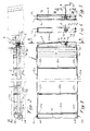
- FIG 1 is a perspective view of the control device according to the present invention which is mounted on the open top body of a common vehicle some parts of which being drawn with a thin line for clarity reasons.
- the Figure 2 shows a lateral view of the control device according to the present invention which is mounted on the generically open top body of a preferred vehicle wherein the maximum extended position of the covering tarpaulin is shown in heavy dashed lines and the maximum retracted uncovering position of the tarpaulin is indicated by light dot-dashed lines.
- the Figure 3 is a plan view of only the open top body and its control device sectioned along the line I - I of the Figure 2, wherein the retracted position of the centerings supporting the tarpaulin is indicated in light dashed lines.
- the Figure 4 is a sectional view taken along the line II-II in the Figure 3 illustrating only the position of the main components, the movement group and return sheaves, which are placed in the tubular telescopic element applied to the upper-front portion of the front wall of the open top body.
- the Figure 5 illustrates, as the Figure 4, the same tubular telescopic casing but including the cables used to move the covering of the open top body.
- the Figure 6 is an enlarged sectional view, taken along the line III - III in the Figure 5, of the movement group housed in the tubular telescopic casing.
- the Figure 7 is a further enlarged and detailed view of the grooved rims of the pulleys included in the movement group illustrated in the previous Figure 6.
- the Figure 8 is a partially broken front view of the telescopic centering used to support covering sheets of different width.
- the open top body I has a bottom 11, the lateral gates 12d and 12s, the rear movable gate 13 and the front fixed wall 14.
- control device forming the object of the present invention is applied to the above mentioned open top body 1 and it is clearly and completely illustrated in the Figure 1, while the other Figures 2, 3, 4, 5, 6 and 7 show, by means of various views and sections, the components forming the said control device.
- the covering tarpaulin 2 is not shown in the Figures 1 and 3 for illustrative clarity and simplicity reasons.
- the covering tarpaulin 2 is shown only in the Figure 2 where its maximum extended position, or rather the covering position on the whole open top body 1, is indicated in heavy dashed lines, while its retracted position, where the tarpaulin results contracted next to front fixed wall 14 of the open top body 1 and uncovers the whole open top body 1, is indicated by light dot-dashed lines.
- Said tarpaulin 2 is supported by centerings 21a and 21b which are essentially equal one another.
- centerings 21a and 21b have the same structure and are essentially constituted by a central length 23 which is formed by a suitable piece of metallic tube.
- the metallic tube is suitably curved in such a way as to constitute a centering 21a-21b which forms a wall bulging upwards for supporting the tarpaulin 2.
- Said inner pieces 24 have an outer diameter which is equal to the inner diameter of said central length 23 and are moreover curved in the same manner so that they can freely slide within the central length 23.
- tubular pieces 24 are welded to respective short tubular pieces 22a and 22b which are equal one another and are extending orthogonally to the same tubular pieces 24.
- the length of the centerings 21a and 21b can vary in order to be suitable for the various lengths of the open top body 1 on which is mounted the control device forming the object of the present invention.
- the final length can be fixed by means of suitable screws V, rivets or the like.
- centrings 21a and 21b are equal one another, they are different in their application and therefore in their function.
- the centering 21a is solidly fixed on the upper length of the cable 3a by means its short tubular pieces 22a, while the other centerings 21b can slide on said upper length of the cable 3a by means their short tubular pieces 22b.
- the short tubular pieces of the rear centering 21a are fixed on the cable 3a with known means and in known ways, while the short tubular pieces 22b of the movable centerings 21b can freely slide along said upper length of the cable 3a placed inside themselves.
- the short tubular pieces 22a, 22b and the respective length of the upper cable 3a are symmetrically applied to both sides of the open top body, in particular to the upper portion of the lateral gates 12d and 12s.
- said length of the upper cable 3a is a portion of a cable forming an annular element. More precisely, the present embodiment of the invention provides two different cables forming different annular elements which are differing only for the length and therefore, as hereinafter described, for the arrangement only in the front driving part.
- both cable rings 3d and 3s slide within the grooves of the respective rear vertical pulleys 4d and 4s which are applied to the ends of the upper edges of the relative lateral gates 12d and 12s.
- the cable rings 3d and 3s slide within the grooves of the pair of front horizontal pulleys 5d and 5'd , 5s and 5's which are slightly protruding from the lateral ends of a telescopic casing 9 constituted by suitable tubular pieces of square or rectangular cross-section which are slidably nested one within the other.
- the cable rings 3d and 3s roll in a relative groove of a pair of vertical driving pulleys 6a and 6b which are housed in the same telescopic casing 9.
- such telescopic casing 9 as it can be seen from the Figures 1 and 2, is removably or irremovably fixed, by means of known systems and means, on the front-upper portion of the open top body 1, more precisely on the upper-outer portion of the front wall 14 of the open top body 1.
- Such vertical driving pulleys 6a and 6b are solidly connected to bevel gears 7a and 7c respectively, mounted coaxially one in front of the other on the opposite sides of a central bevel gear 7b in which they engage.
- the bevel gear 7b is connected to a driving shaft 8 equipped with a crank 81 in its opposite free end.
- the preferred ratio of the bevel gear 7a velocity to the corresponding bevel gear 7b velocity is of 3 to 1 because it proved to be the most suitable velocity ratio for the use of such control device.
- the right upper lengths 3a , the right lower lengths 3b, the right upper lengths 3c and the right lower lengths 3f constitute the cable ring 3d of the right side and slide, parallel one another, in the grooves of the respective pulleys 4d, 5d, 5'd and 6a.
- the corresponding lengths of the left side namely the left upper length 3a and the left lower length 3b are too parallel one another, and so are also the respective left lengths 3c and 3f.
- grooves 61a and 61b of the driving pulleys 6a and 6b have a width equal to the diameter of the therein engaged cables in order to avoid any slightest slipping of both cable rings 3d and 3s within the grooves 61a and 61b of the respective driving pulleys 6a and 6b but also such grooves are suitably V shaped and their sides converge inwards and present suitably roughened surface in order to enhance friction and to avoid the above mentioned cable slipping.
- the group composed of the horizontal driving pulley 5s, 5's, 5d and 5'd as well as the group constituted by the vertical driving pulleys 6a and 6b which are integral with the driving bevel gears 7a-7c are contained in a box-like telescopic casing 9 which can be lengthened and/or shortened according to the requirements involved by the open top body on which said control device must be used.
- Both cable rings 3d and 3s are suitably tightened by known means and devices in order to assure the frictional grip, between the cables 3d and 3s and the respective driving pulleys 6a and 6b, and to avoid any slightest slipping of both cable rings 3d and 3s within the grooves 61a and 61b.
- the tensioning of the cable rings 3d and 3s is obtained, by way of example, by placing the rear vertical pulleys 4d and 4s on respective tightening devices 41d and 41s which urge rearwards thus operating a progressive tightening of the respective cable rings 3d and 3s.
- crank 81 and the relative driving shaft 8 it is possible to rotate the bevel gears 7a-7c which consequently rotate also the driving pulleys 6a and 6b in opposite rotating directions.
- the upper portion of the cable length 3a of both the right and the left side causes the movement of the first centering 21a, which is fixed to the cable length 3a of both the right and the left side by means of the respective tubular pieces 22a. Therefore, the centering 21a is moved away from the front wall 14 and toward the rear movable gate 13.
- the progressive change in the position of the centering 21a causes the following centerings 21b to be pulled in motion by the progressive unfolding of the tarpaulin.
- control device forming the object of the present invention comes also from the fact that the cross between the first lengths 3c and 3f, exactly the lengths comprised between the driving pulley 6b and the horizontal pulleys 5s and 5's can be avoided, what allows to set in motion both the upper length 3a and the lower length 3b of the cable ring 3s in the same direction of the corresponding upper length 3a and lower length 3b of the cable ring 3d without risking the slipping out of the cable from the pulleys 5'd and 5's.
- control device forming the object of the present invention is constituted by very simple as well as commercially available components and it is easy to operate, easy to install as well as adjustable to any kinds of open top bodies in the industrial, agricultural and/or similar vehicles.
Landscapes
- Engineering & Computer Science (AREA)
- Mechanical Engineering (AREA)
- Power-Operated Mechanisms For Wings (AREA)
- Tents Or Canopies (AREA)
- Lock And Its Accessories (AREA)
- Control And Other Processes For Unpacking Of Materials (AREA)
Abstract
Description
- The present invention relates to a control device for both opening and closing the sheets used to cover the open top bodies in the industrial, agricultural and/or similar vehicles. Such control device allows to open as well as to close the sheets or tarpaulins for covering the bodies of the vehicles by means of easy and simple operations.
- As they are well known, above all and not only, in the industrial vehicles field, sheets or tarpaulins are used to cover the so-called open top boxes or bodies of the vehicles in order to cover, protect, hold in place and therefore to prevent the spilling of the transported materials.
- In case of the transport of unstable and loose materials, as for example sand, gravel and such construction materials, the aerodynamic turbulence can take them away from their loading place in the body of the vehicle and release them on the following vehicles.
- This causes driving troubles and accident risks due to poor visibility, windshield cracking or breaking in the following vehicles as well as to other drawbacks as the defilement or the eventual pollution of the road surface. Different solutions are already known in the field of the sheets used to cover the vehicles bodies.
- Such solutions are complicated, expensive and must be each time realized according to the real dimensions of the vehicle body to be covered, thereby involving long working times and difficult operations for their application.
- Moreover, such solutions imply complicated systems which are for example composed by drive shafting to transmit rotary motion and power to the centerings supporting the tarpaulin.
- Such shafting are equipped with conical pairs, to transmit their rotary motion to other shafts which are placed in the corners of said open top bodies, and they require reduction gears in order to lower the stress to be applied for moving the whole system.
- The above described systems are not easy to operate by manual operations because they are very heavy and produce remarkable frictional forces even though they are equipped with reduction gear. Therefore, such systems require auxiliary actuating means as electric motors or other similar means.
- The
EP 1 228 912 - It is therefore an object of the present invention to provide an easy to operate, structurally simple and secure control device for opening and closing the cover sheets of vehicles, allowing a symmetrical distribution of the cable tension on both sides of the vehicle top body and a linear and secure sliding of said cable in the driving pulleys.
- A system constituting a solution to this problem is defined in
claim 1. Other advantageous aspects of the invention are defined in the dependent claims. - For a better comprehension of the subject-matter of the present invention reference is made hereinafter to the enclosed figures. In order to allow an easy and secure tightening of the cable rings (3d and 3s) sliding along the lateral gates of the open top body of a vehicle, the present invention provides a control device where the driving pulleys (6a-6b) are set in motion by means of bevel gears (7a, 7b and 7c), wherein the
gear 7a with the drivingpulley 6a and the gear 7c with the drivingpulley 6b are mounted coaxially one in front of the other on the opposite sides of the central bevel gear 7b which is manually driven by means of the crank (81) and its driving shaft (8). The lengths of the cable rings (3c and 3f) extending between said pulleys (5d-5'd and 5s-5's) are disposed parallel one another so that the upper lateral lengths (3a) move in the same directions. - By means of this device, it is therefore possible to distribute uniformly the cable tension from the
pulleys - Figure 1 is a perspective view of the control device according to the present invention which is mounted on the open top body of a common vehicle some parts of which being drawn with a thin line for clarity reasons.
The Figure 2 shows a lateral view of the control device according to the present invention which is mounted on the generically open top body of a preferred vehicle wherein the maximum extended position of the covering tarpaulin is shown in heavy dashed lines and the maximum retracted uncovering position of the tarpaulin is indicated by light dot-dashed lines.
The Figure 3 is a plan view of only the open top body and its control device sectioned along the line I - I of the Figure 2, wherein the retracted position of the centerings supporting the tarpaulin is indicated in light dashed lines. The Figure 4 is a sectional view taken along the line II-II in the Figure 3 illustrating only the position of the main components, the movement group and return sheaves, which are placed in the tubular telescopic element applied to the upper-front portion of the front wall of the open top body. The Figure 5 illustrates, as the Figure 4, the same tubular telescopic casing but including the cables used to move the covering of the open top body.
The Figure 6 is an enlarged sectional view, taken along the line III - III in the Figure 5, of the movement group housed in the tubular telescopic casing.
The Figure 7 is a further enlarged and detailed view of the grooved rims of the pulleys included in the movement group illustrated in the previous Figure 6.
The Figure 8 is a partially broken front view of the telescopic centering used to support covering sheets of different width. - In the above mentioned figures, the common items are marked with the same reference numbers.
- With particular reference to Figures 1, 2, and 3 it is to be noticed the open
top body 1 of a generic industrial vehicle (indicated in thin lines) in which is mounted the control device according to the present invention. - The open top body I has a
bottom 11, thelateral gates 12d and 12s, the rearmovable gate 13 and the front fixedwall 14. - The control device forming the object of the present invention is applied to the above mentioned open
top body 1 and it is clearly and completely illustrated in the Figure 1, while the other Figures 2, 3, 4, 5, 6 and 7 show, by means of various views and sections, the components forming the said control device. - According to such a control device, the covering tarpaulin 2 is not shown in the Figures 1 and 3 for illustrative clarity and simplicity reasons.
- On the contrary, the covering tarpaulin 2 is shown only in the Figure 2 where its maximum extended position, or rather the covering position on the whole
open top body 1, is indicated in heavy dashed lines, while its retracted position, where the tarpaulin results contracted next to frontfixed wall 14 of the opentop body 1 and uncovers the whole opentop body 1, is indicated by light dot-dashed lines. - Said tarpaulin 2 is supported by
centerings - As it can be seen in Figures 1, 2, 3 and with particular reference to Figure 8, said centerings are composed of tubular and telescopically adjustable elements which are hereinafter in detail described.
With reference to said Figure 8, it is to be noticed thatsuch centerings central length 23 which is formed by a suitable piece of metallic tube. The metallic tube is suitably curved in such a way as to constitute a centering 21a-21b which forms a wall bulging upwards for supporting the tarpaulin 2. - In the ends of the tubular piece forming the
central length 23 are nested respective tubular pieces 24. Said inner pieces 24 have an outer diameter which is equal to the inner diameter of saidcentral length 23 and are moreover curved in the same manner so that they can freely slide within thecentral length 23. - The outer ends of said tubular pieces 24 are welded to respective short
tubular pieces - Clearly, the result is that the length of the
centerings open top body 1 on which is mounted the control device forming the object of the present invention. The final length can be fixed by means of suitable screws V, rivets or the like. - Even though said
centrings - More precisely, the centering 21a is solidly fixed on the upper length of the cable 3a by means its short
tubular pieces 22a, while theother centerings 21b can slide on said upper length of the cable 3a by means their shorttubular pieces 22b. - Practically, the short tubular pieces of the rear centering 21a are fixed on the cable 3a with known means and in known ways, while the short
tubular pieces 22b of themovable centerings 21b can freely slide along said upper length of the cable 3a placed inside themselves. - Clearly, the short
tubular pieces lateral gates 12d and 12s. - With reference to the above-mentioned figures of the drawings, said length of the upper cable 3a is a portion of a cable forming an annular element. More precisely, the present embodiment of the invention provides two different cables forming different annular elements which are differing only for the length and therefore, as hereinafter described, for the arrangement only in the front driving part.
- The so resulting two cable rings are marked with the
reference numbers 3d and 3s because they are used on two different sides. - Practically, both
cable rings 3d and 3s slide within the grooves of the respective rearvertical pulleys 4d and 4s which are applied to the ends of the upper edges of the relativelateral gates 12d and 12s. - At this point, the
cable rings 3d and 3s slide within the grooves of the pair of fronthorizontal pulleys 5d and 5'd , 5s and 5's which are slightly protruding from the lateral ends of atelescopic casing 9 constituted by suitable tubular pieces of square or rectangular cross-section which are slidably nested one within the other. - After which, the
cable rings 3d and 3s roll in a relative groove of a pair ofvertical driving pulleys telescopic casing 9. - It is to be pointed out that such
telescopic casing 9, as it can be seen from the Figures 1 and 2, is removably or irremovably fixed, by means of known systems and means, on the front-upper portion of theopen top body 1, more precisely on the upper-outer portion of thefront wall 14 of the opentop body 1. - Such
vertical driving pulleys bevel gears 7a and 7c respectively, mounted coaxially one in front of the other on the opposite sides of a central bevel gear 7b in which they engage. The bevel gear 7b is connected to adriving shaft 8 equipped with acrank 81 in its opposite free end. - For clarity reasons, the particular group composed of the pair of
vertical driving pulleys driving bevel gears 7a-7c, is shown in the enlarged view of Figure 6. - Moreover, the particular shape of the
grooves 61a and 61b in saidvertical driving pulleys - It is to be pointed out that in the described embodiment of the invention the preferred ratio of the
bevel gear 7a velocity to the corresponding bevel gear 7b velocity is of 3 to 1 because it proved to be the most suitable velocity ratio for the use of such control device. - It is well understood that the movement of the vertical driving pulleys 6a and 6b can be effected by means of a suitable power group, as for example a motor reducer and/or similar means rather than systems which require manual operations.
- It is to be pointed out that the right upper lengths 3a , the right
lower lengths 3b, the rightupper lengths 3c and the rightlower lengths 3f constitute thecable ring 3d of the right side and slide, parallel one another, in the grooves of therespective pulleys - The corresponding lengths of the left side, namely the left upper length 3a and the left
lower length 3b are too parallel one another, and so are also the respectiveleft lengths - As it can clearly seen from the Figure 7, it is to be pointed out that not only the
grooves 61a and 61b of the drivingpulleys grooves 61a and 61b of therespective driving pulleys - After the description of all the components for moving the tarpaulin it is to be pointed out that the group composed of the horizontal driving pulley 5s, 5's, 5d and 5'd as well as the group constituted by the vertical driving pulleys 6a and 6b which are integral with the driving
bevel gears 7a-7c are contained in a box-liketelescopic casing 9 which can be lengthened and/or shortened according to the requirements involved by the open top body on which said control device must be used.
Both cable rings 3d and 3s are suitably tightened by known means and devices in order to assure the frictional grip, between thecables 3d and 3s and therespective driving pulleys grooves 61a and 61b. - In the present embodiment, the tensioning of the cable rings 3d and 3s is obtained, by way of example, by placing the rear
vertical pulleys 4d and 4s onrespective tightening devices 41d and 41s which urge rearwards thus operating a progressive tightening of the respective cable rings 3d and 3s. After the description of the structural composition of the control device forming the object of the present invention, it is now described its manner of operating. - By means of the
crank 81 and therelative driving shaft 8 it is possible to rotate thebevel gears 7a-7c which consequently rotate also the drivingpulleys - Starting from the position wherein the tarpaulin is folded and placed near the
front wall 14, the rotation of saidpulleys - Thus, the upper portion of the cable length 3a of both the right and the left side causes the movement of the first centering 21a, which is fixed to the cable length 3a of both the right and the left side by means of the respective
tubular pieces 22a. Therefore, the centering 21a is moved away from thefront wall 14 and toward the rearmovable gate 13. - The progressive change in the position of the centering 21a causes the following
centerings 21b to be pulled in motion by the progressive unfolding of the tarpaulin. - Such operation goes on till the complete covering of the open
top body 1. - It is obvious that by rotating the
crank 81, the drivingshaft 8 and the driving group constituted by thebevel gears 7a-7c and drivingpulleys centerings top body 1 as it is clearly indicated by light dashed lines in the Figures 1, 2 and 3. - The particularity of the control device forming the object of the present invention comes also from the fact that the cross between the
first lengths pulley 6b and the horizontal pulleys 5s and 5's can be avoided, what allows to set in motion both the upper length 3a and thelower length 3b of the cable ring 3s in the same direction of the corresponding upper length 3a andlower length 3b of thecable ring 3d without risking the slipping out of the cable from the pulleys 5'd and 5's. - From what described it is clear that the control device forming the object of the present invention is constituted by very simple as well as commercially available components and it is easy to operate, easy to install as well as adjustable to any kinds of open top bodies in the industrial, agricultural and/or similar vehicles.
- Moreover, all components are made as parts of a so-called do-it-yourself kit in order to reduce the installation costs. Therefore, such parts of the do-it-yourself kit are made in such a way as to be easily and directly assembled also by not-skilled persons and without the need of special-purpose tools which may be obtained only by special machine shops.
- It is well understood that modifications and variations may be made to the control device forming the object of the present invention without departing however from the scope defined by the following claims with reference to the accompanying drawings and thence from the protection extent of the present industrial invention.
Claims (5)
- Control device for both opening and closing the sheets or tarpaulins used to cover the open top bodies in the industrial, agricultural and/or similar vehicles wherein respective cable rings (3d and 3s) are sliding along the lateral gates (12d and 12s) of an open top body (1) of a vehicle as for example a truck or similar, centerings (21a and 21b), supporting the tarpaulin (2) fixed thereon, are placed on the right and left upper lengths (3a) of such cable rings (3d and 3s), the centering (21a) facing to the rear part of the open top body (1) being fixed, by means of short tubular pieces (22a) of its the lateral ends, on the corresponding upper lengths (3a) of said cable rings (3d and 3s) on the right and left side respectively, while the following centerings (21b) are sliding on said upper lengths (3a); the said cable rings (3d and 3s) result tightened between the rear lateral pulleys (4d and 4s), which are applied to the rear ends of the upper edges of the relative lateral gates (12d and 12s), and the vertical driving pulleys (6a and 6b) which are housed in the telescopic casing (9) passing through the pairs of pulleys (5d-5'd and 5s-5's) which are slightly protruding from the lateral ends of the same casing (9) and presenting their respective grooves at the same height and in alignment with the grooves of the pulleys (4d and 4s),
characterised in that said driving pulleys (6a-6b) are set in motion by means of bevel gears (7a, 7b and 7c), wherein the gear 7a with the driving pulley 6a and the gear 7c with the driving pulley 6b are mounted coaxially one in front of the other on the opposite sides of the central bevel gear 7b which is manually driven by means of the crank (81) and its driving shaft (8), and in that the lengths of the cable rings (3c and 3f) extending between said pulleys (5d-5'd and 5s-5's) are disposed parallel one another so that the upper lateral lengths (3a) move in the same directions. - Control device according to claim 1,
characterized in that the said rear vertical pulleys (4d and 4s) are applied to respective tightening devices (41d and 41s) which are suitably driven in order to urge the pulleys (4d and 4s) rearwards and out from the vertical driving pulleys (6a and 6b) thus allowing a suitable tensioning of the relative cables (3d and 3s) as well as avoiding any slightest slipping of the lengths of the cable rings (3d and 3s) engaged within the grooves (61a and 61b) of the respective vertical driving pulleys (6a and 6b). - Control device according to claim 1 or 2,
characterized in that said centerings (21a and 21b) are substantially made in a telescopic manner thus allowing their adjustment to open top bodies (1) of different widths. - Control device according to claim 1,
characterized in that said telescopic casing (9) is constituted by tubular pieces of square or rectangular cross-section, which are slidably nested one within the other, and it can be removable or irremovably fixed on the upper-outer portion of the front wall (14) of the open top body (1). - Control device according to one of the claims 1 to 4,
characterized in that the movement of the whole group of pulleys, cables and other movable parts of the control device can be obtained as well by manual operations as by means of service accessories as motor reducer and/or similar means.
Priority Applications (4)
| Application Number | Priority Date | Filing Date | Title |
|---|---|---|---|
| ES05105886T ES2302129T3 (en) | 2005-06-30 | 2005-06-30 | CONTROL DEVICE FOR OPENING AND CLOSING DRAWERS WITH OPEN UPPER PART IN INDUSTRIAL VEHICLES. |
| EP05105886A EP1738946B8 (en) | 2005-06-30 | 2005-06-30 | Control device for opening and closing open top bodies in industrial vehicles |
| DE602005004905T DE602005004905T2 (en) | 2005-06-30 | 2005-06-30 | Control device for opening and closing an open-topped container for commercial vehicles |
| AT05105886T ATE386653T1 (en) | 2005-06-30 | 2005-06-30 | CONTROL DEVICE FOR OPENING AND CLOSING AN OPEN-TOP CONTAINER FOR COMMERCIAL VEHICLES |
Applications Claiming Priority (1)
| Application Number | Priority Date | Filing Date | Title |
|---|---|---|---|
| EP05105886A EP1738946B8 (en) | 2005-06-30 | 2005-06-30 | Control device for opening and closing open top bodies in industrial vehicles |
Publications (3)
| Publication Number | Publication Date |
|---|---|
| EP1738946A1 true EP1738946A1 (en) | 2007-01-03 |
| EP1738946B1 EP1738946B1 (en) | 2008-02-20 |
| EP1738946B8 EP1738946B8 (en) | 2008-04-23 |
Family
ID=35385583
Family Applications (1)
| Application Number | Title | Priority Date | Filing Date |
|---|---|---|---|
| EP05105886A Active EP1738946B8 (en) | 2005-06-30 | 2005-06-30 | Control device for opening and closing open top bodies in industrial vehicles |
Country Status (4)
| Country | Link |
|---|---|
| EP (1) | EP1738946B8 (en) |
| AT (1) | ATE386653T1 (en) |
| DE (1) | DE602005004905T2 (en) |
| ES (1) | ES2302129T3 (en) |
Cited By (5)
| Publication number | Priority date | Publication date | Assignee | Title |
|---|---|---|---|---|
| WO2007124787A1 (en) * | 2006-12-20 | 2007-11-08 | Trakover S.R.L. | Control device for opening and closing open top bodies in industrial vehicles |
| EP2233335A1 (en) | 2009-03-25 | 2010-09-29 | Marcolin S.r.l. | Driving mechanism for covering canvas of lorries |
| EP2311678A1 (en) | 2009-10-14 | 2011-04-20 | Marcolin S.r.l. | Improved operator for covering canvas of vehicles |
| WO2011070400A1 (en) | 2009-12-11 | 2011-06-16 | Marcolin S.R.L. | Actuation system for covering canvas of top-bodies |
| EP2371597A1 (en) | 2010-03-29 | 2011-10-05 | Marcolin S.r.l. | Actuator for covering canvas of top-bodies |
Citations (3)
| Publication number | Priority date | Publication date | Assignee | Title |
|---|---|---|---|---|
| WO1996033882A1 (en) * | 1995-04-26 | 1996-10-31 | Denyer David K | Retractable tarpaulin cover apparatus for open-topped containers such as truck bodies |
| EP1228912A2 (en) * | 2001-01-31 | 2002-08-07 | Bortolin Regina di Pivetta IVO & C. S.n.C. | Control device for opening and closing open top bodies in industrial vehicles |
| EP1529671A2 (en) * | 2003-11-07 | 2005-05-11 | Ambrogio Lippolis | Cabriolet cover for trucks |
-
2005
- 2005-06-30 DE DE602005004905T patent/DE602005004905T2/en active Active
- 2005-06-30 EP EP05105886A patent/EP1738946B8/en active Active
- 2005-06-30 ES ES05105886T patent/ES2302129T3/en active Active
- 2005-06-30 AT AT05105886T patent/ATE386653T1/en not_active IP Right Cessation
Patent Citations (3)
| Publication number | Priority date | Publication date | Assignee | Title |
|---|---|---|---|---|
| WO1996033882A1 (en) * | 1995-04-26 | 1996-10-31 | Denyer David K | Retractable tarpaulin cover apparatus for open-topped containers such as truck bodies |
| EP1228912A2 (en) * | 2001-01-31 | 2002-08-07 | Bortolin Regina di Pivetta IVO & C. S.n.C. | Control device for opening and closing open top bodies in industrial vehicles |
| EP1529671A2 (en) * | 2003-11-07 | 2005-05-11 | Ambrogio Lippolis | Cabriolet cover for trucks |
Cited By (6)
| Publication number | Priority date | Publication date | Assignee | Title |
|---|---|---|---|---|
| WO2007124787A1 (en) * | 2006-12-20 | 2007-11-08 | Trakover S.R.L. | Control device for opening and closing open top bodies in industrial vehicles |
| US8220860B2 (en) | 2006-12-20 | 2012-07-17 | Trakover S.R.L. | Control device for opening and closing open top bodies in industrial vehicles |
| EP2233335A1 (en) | 2009-03-25 | 2010-09-29 | Marcolin S.r.l. | Driving mechanism for covering canvas of lorries |
| EP2311678A1 (en) | 2009-10-14 | 2011-04-20 | Marcolin S.r.l. | Improved operator for covering canvas of vehicles |
| WO2011070400A1 (en) | 2009-12-11 | 2011-06-16 | Marcolin S.R.L. | Actuation system for covering canvas of top-bodies |
| EP2371597A1 (en) | 2010-03-29 | 2011-10-05 | Marcolin S.r.l. | Actuator for covering canvas of top-bodies |
Also Published As
| Publication number | Publication date |
|---|---|
| EP1738946B1 (en) | 2008-02-20 |
| DE602005004905T2 (en) | 2009-02-26 |
| EP1738946B8 (en) | 2008-04-23 |
| ATE386653T1 (en) | 2008-03-15 |
| ES2302129T3 (en) | 2008-07-01 |
| DE602005004905D1 (en) | 2008-04-03 |
Similar Documents
| Publication | Publication Date | Title |
|---|---|---|
| AU2006343004B2 (en) | Control device for opening and closing open top bodies in industrial vehicles | |
| EP1754618B1 (en) | Device for controlling opening and closing of tarpaulins for covering the bodies of industrial, agricultural and similar vehicles | |
| EP1738946B1 (en) | Control device for opening and closing open top bodies in industrial vehicles | |
| US3910629A (en) | Telescopic cover for the load-carrying body of a truck | |
| WO2011077316A1 (en) | Control device for opening and closing open top bodies in industrial vehicles | |
| EP1228912B1 (en) | Control device for opening and closing open top bodies in industrial vehicles | |
| CN105916744B (en) | For the height adjustable support of vehicle | |
| DE102013221558B4 (en) | net device | |
| CN102848965A (en) | Automatically folded and unfolded truck tarpaulin | |
| CN211197282U (en) | Tarpaulin folding and unfolding device and container with tarpaulin folding and unfolding device | |
| CN203902376U (en) | Coverage structure for boxcar | |
| RU2373076C2 (en) | Device to open and close vehicle open body | |
| CN219671902U (en) | Rotatable and telescopic shutter awning | |
| EP3165387B1 (en) | Actuating and towing device for a cover system on secured guides for a truck-body | |
| CN219622135U (en) | Rotatable and telescopic shutter awning | |
| CN203613847U (en) | Lifting elevator structure of parking device | |
| DE102020003981B4 (en) | Tarpaulin with integrated drive for temporarily closing openings | |
| CN211247865U (en) | Automatic bending device for canopy frame pipe for trailer | |
| CN211844060U (en) | Telescopic sun-shading umbrella device | |
| CN215160802U (en) | Aerial work platform capable of automatically extending and aerial work vehicle thereof | |
| CN113276763A (en) | Interior plaque atmosphere lamp of car door | |
| JPH09228646A (en) | Temporary tent with bidirectional moving truck | |
| DE4300785A1 (en) | Expandable caravan or trailer |
Legal Events
| Date | Code | Title | Description |
|---|---|---|---|
| PUAI | Public reference made under article 153(3) epc to a published international application that has entered the european phase |
Free format text: ORIGINAL CODE: 0009012 |
|
| AK | Designated contracting states |
Kind code of ref document: A1 Designated state(s): AT BE BG CH CY CZ DE DK EE ES FI FR GB GR HU IE IS IT LI LT LU MC NL PL PT RO SE SI SK TR |
|
| AX | Request for extension of the european patent |
Extension state: AL BA HR LV MK YU |
|
| 17P | Request for examination filed |
Effective date: 20070412 |
|
| GRAP | Despatch of communication of intention to grant a patent |
Free format text: ORIGINAL CODE: EPIDOSNIGR1 |
|
| AKX | Designation fees paid |
Designated state(s): AT BE BG CH CY CZ DE DK EE ES FI FR GB GR HU IE IS IT LI LT LU MC NL PL PT RO SE SI SK TR |
|
| GRAS | Grant fee paid |
Free format text: ORIGINAL CODE: EPIDOSNIGR3 |
|
| GRAA | (expected) grant |
Free format text: ORIGINAL CODE: 0009210 |
|
| RAP1 | Party data changed (applicant data changed or rights of an application transferred) |
Owner name: TRAKOVER SRL |
|
| AK | Designated contracting states |
Kind code of ref document: B1 Designated state(s): AT BE BG CH CY CZ DE DK EE ES FI FR GB GR HU IE IS IT LI LT LU MC NL PL PT RO SE SI SK TR |
|
| REG | Reference to a national code |
Ref country code: GB Ref legal event code: FG4D |
|
| RIN1 | Information on inventor provided before grant (corrected) |
Inventor name: PIVETTA, CESARINOBORTOLIN REGINA DI PIVETTA IVO & |
|
| RAP2 | Party data changed (patent owner data changed or rights of a patent transferred) |
Owner name: TRAKOVER SRL |
|
| REG | Reference to a national code |
Ref country code: CH Ref legal event code: EP |
|
| REG | Reference to a national code |
Ref country code: IE Ref legal event code: FG4D |
|
| REF | Corresponds to: |
Ref document number: 602005004905 Country of ref document: DE Date of ref document: 20080403 Kind code of ref document: P |
|
| NLT2 | Nl: modifications (of names), taken from the european patent patent bulletin |
Owner name: TRAKOVER SRL Effective date: 20080305 |
|
| REG | Reference to a national code |
Ref country code: ES Ref legal event code: FG2A Ref document number: 2302129 Country of ref document: ES Kind code of ref document: T3 |
|
| PG25 | Lapsed in a contracting state [announced via postgrant information from national office to epo] |
Ref country code: FI Free format text: LAPSE BECAUSE OF FAILURE TO SUBMIT A TRANSLATION OF THE DESCRIPTION OR TO PAY THE FEE WITHIN THE PRESCRIBED TIME-LIMIT Effective date: 20080220 Ref country code: IS Free format text: LAPSE BECAUSE OF FAILURE TO SUBMIT A TRANSLATION OF THE DESCRIPTION OR TO PAY THE FEE WITHIN THE PRESCRIBED TIME-LIMIT Effective date: 20080620 |
|
| NLV1 | Nl: lapsed or annulled due to failure to fulfill the requirements of art. 29p and 29m of the patents act | ||
| ET | Fr: translation filed | ||
| PG25 | Lapsed in a contracting state [announced via postgrant information from national office to epo] |
Ref country code: AT Free format text: LAPSE BECAUSE OF FAILURE TO SUBMIT A TRANSLATION OF THE DESCRIPTION OR TO PAY THE FEE WITHIN THE PRESCRIBED TIME-LIMIT Effective date: 20080220 |
|
| PG25 | Lapsed in a contracting state [announced via postgrant information from national office to epo] |
Ref country code: SI Free format text: LAPSE BECAUSE OF FAILURE TO SUBMIT A TRANSLATION OF THE DESCRIPTION OR TO PAY THE FEE WITHIN THE PRESCRIBED TIME-LIMIT Effective date: 20080220 Ref country code: PL Free format text: LAPSE BECAUSE OF FAILURE TO SUBMIT A TRANSLATION OF THE DESCRIPTION OR TO PAY THE FEE WITHIN THE PRESCRIBED TIME-LIMIT Effective date: 20080220 |
|
| PG25 | Lapsed in a contracting state [announced via postgrant information from national office to epo] |
Ref country code: CZ Free format text: LAPSE BECAUSE OF FAILURE TO SUBMIT A TRANSLATION OF THE DESCRIPTION OR TO PAY THE FEE WITHIN THE PRESCRIBED TIME-LIMIT Effective date: 20080220 Ref country code: NL Free format text: LAPSE BECAUSE OF FAILURE TO SUBMIT A TRANSLATION OF THE DESCRIPTION OR TO PAY THE FEE WITHIN THE PRESCRIBED TIME-LIMIT Effective date: 20080220 Ref country code: SK Free format text: LAPSE BECAUSE OF FAILURE TO SUBMIT A TRANSLATION OF THE DESCRIPTION OR TO PAY THE FEE WITHIN THE PRESCRIBED TIME-LIMIT Effective date: 20080220 Ref country code: DK Free format text: LAPSE BECAUSE OF FAILURE TO SUBMIT A TRANSLATION OF THE DESCRIPTION OR TO PAY THE FEE WITHIN THE PRESCRIBED TIME-LIMIT Effective date: 20080220 Ref country code: SE Free format text: LAPSE BECAUSE OF FAILURE TO SUBMIT A TRANSLATION OF THE DESCRIPTION OR TO PAY THE FEE WITHIN THE PRESCRIBED TIME-LIMIT Effective date: 20080520 Ref country code: PT Free format text: LAPSE BECAUSE OF FAILURE TO SUBMIT A TRANSLATION OF THE DESCRIPTION OR TO PAY THE FEE WITHIN THE PRESCRIBED TIME-LIMIT Effective date: 20080721 |
|
| PG25 | Lapsed in a contracting state [announced via postgrant information from national office to epo] |
Ref country code: RO Free format text: LAPSE BECAUSE OF FAILURE TO SUBMIT A TRANSLATION OF THE DESCRIPTION OR TO PAY THE FEE WITHIN THE PRESCRIBED TIME-LIMIT Effective date: 20080220 |
|
| PLBE | No opposition filed within time limit |
Free format text: ORIGINAL CODE: 0009261 |
|
| STAA | Information on the status of an ep patent application or granted ep patent |
Free format text: STATUS: NO OPPOSITION FILED WITHIN TIME LIMIT |
|
| 26N | No opposition filed |
Effective date: 20081121 |
|
| PG25 | Lapsed in a contracting state [announced via postgrant information from national office to epo] |
Ref country code: MC Free format text: LAPSE BECAUSE OF NON-PAYMENT OF DUE FEES Effective date: 20080630 Ref country code: LT Free format text: LAPSE BECAUSE OF FAILURE TO SUBMIT A TRANSLATION OF THE DESCRIPTION OR TO PAY THE FEE WITHIN THE PRESCRIBED TIME-LIMIT Effective date: 20080220 |
|
| REG | Reference to a national code |
Ref country code: IE Ref legal event code: MM4A |
|
| PG25 | Lapsed in a contracting state [announced via postgrant information from national office to epo] |
Ref country code: BG Free format text: LAPSE BECAUSE OF FAILURE TO SUBMIT A TRANSLATION OF THE DESCRIPTION OR TO PAY THE FEE WITHIN THE PRESCRIBED TIME-LIMIT Effective date: 20080520 Ref country code: EE Free format text: LAPSE BECAUSE OF FAILURE TO SUBMIT A TRANSLATION OF THE DESCRIPTION OR TO PAY THE FEE WITHIN THE PRESCRIBED TIME-LIMIT Effective date: 20080220 Ref country code: IE Free format text: LAPSE BECAUSE OF NON-PAYMENT OF DUE FEES Effective date: 20080630 |
|
| PG25 | Lapsed in a contracting state [announced via postgrant information from national office to epo] |
Ref country code: CY Free format text: LAPSE BECAUSE OF FAILURE TO SUBMIT A TRANSLATION OF THE DESCRIPTION OR TO PAY THE FEE WITHIN THE PRESCRIBED TIME-LIMIT Effective date: 20080220 |
|
| REG | Reference to a national code |
Ref country code: CH Ref legal event code: PL |
|
| PG25 | Lapsed in a contracting state [announced via postgrant information from national office to epo] |
Ref country code: LI Free format text: LAPSE BECAUSE OF NON-PAYMENT OF DUE FEES Effective date: 20090630 Ref country code: CH Free format text: LAPSE BECAUSE OF NON-PAYMENT OF DUE FEES Effective date: 20090630 |
|
| PG25 | Lapsed in a contracting state [announced via postgrant information from national office to epo] |
Ref country code: LU Free format text: LAPSE BECAUSE OF NON-PAYMENT OF DUE FEES Effective date: 20080630 Ref country code: HU Free format text: LAPSE BECAUSE OF FAILURE TO SUBMIT A TRANSLATION OF THE DESCRIPTION OR TO PAY THE FEE WITHIN THE PRESCRIBED TIME-LIMIT Effective date: 20080821 |
|
| PG25 | Lapsed in a contracting state [announced via postgrant information from national office to epo] |
Ref country code: TR Free format text: LAPSE BECAUSE OF FAILURE TO SUBMIT A TRANSLATION OF THE DESCRIPTION OR TO PAY THE FEE WITHIN THE PRESCRIBED TIME-LIMIT Effective date: 20080220 |
|
| PG25 | Lapsed in a contracting state [announced via postgrant information from national office to epo] |
Ref country code: GR Free format text: LAPSE BECAUSE OF FAILURE TO SUBMIT A TRANSLATION OF THE DESCRIPTION OR TO PAY THE FEE WITHIN THE PRESCRIBED TIME-LIMIT Effective date: 20080521 |
|
| REG | Reference to a national code |
Ref country code: FR Ref legal event code: PLFP Year of fee payment: 12 |
|
| REG | Reference to a national code |
Ref country code: FR Ref legal event code: PLFP Year of fee payment: 13 |
|
| PGFP | Annual fee paid to national office [announced via postgrant information from national office to epo] |
Ref country code: CZ Payment date: 20170510 Year of fee payment: 13 |
|
| REG | Reference to a national code |
Ref country code: FR Ref legal event code: PLFP Year of fee payment: 14 |
|
| GBPC | Gb: european patent ceased through non-payment of renewal fee |
Effective date: 20180630 |
|
| PG25 | Lapsed in a contracting state [announced via postgrant information from national office to epo] |
Ref country code: GB Free format text: LAPSE BECAUSE OF NON-PAYMENT OF DUE FEES Effective date: 20180630 |
|
| REG | Reference to a national code |
Ref country code: DE Ref legal event code: R082 Ref document number: 602005004905 Country of ref document: DE Representative=s name: MEISSNER BOLTE PATENTANWAELTE RECHTSANWAELTE P, DE |
|
| PGFP | Annual fee paid to national office [announced via postgrant information from national office to epo] |
Ref country code: IT Payment date: 20220622 Year of fee payment: 18 Ref country code: DE Payment date: 20220429 Year of fee payment: 18 |
|
| PGFP | Annual fee paid to national office [announced via postgrant information from national office to epo] |
Ref country code: BE Payment date: 20220627 Year of fee payment: 18 |
|
| PGFP | Annual fee paid to national office [announced via postgrant information from national office to epo] |
Ref country code: FR Payment date: 20220623 Year of fee payment: 18 |
|
| PGFP | Annual fee paid to national office [announced via postgrant information from national office to epo] |
Ref country code: ES Payment date: 20220714 Year of fee payment: 18 |
|
| P01 | Opt-out of the competence of the unified patent court (upc) registered |
Effective date: 20230603 |
|
| REG | Reference to a national code |
Ref country code: DE Ref legal event code: R119 Ref document number: 602005004905 Country of ref document: DE |
|
| REG | Reference to a national code |
Ref country code: BE Ref legal event code: MM Effective date: 20230630 |
|
| PG25 | Lapsed in a contracting state [announced via postgrant information from national office to epo] |
Ref country code: DE Free format text: LAPSE BECAUSE OF NON-PAYMENT OF DUE FEES Effective date: 20240103 |