EP1738874A2 - Apparatus and method for marking of turbine blades - Google Patents
Apparatus and method for marking of turbine blades Download PDFInfo
- Publication number
- EP1738874A2 EP1738874A2 EP06253419A EP06253419A EP1738874A2 EP 1738874 A2 EP1738874 A2 EP 1738874A2 EP 06253419 A EP06253419 A EP 06253419A EP 06253419 A EP06253419 A EP 06253419A EP 1738874 A2 EP1738874 A2 EP 1738874A2
- Authority
- EP
- European Patent Office
- Prior art keywords
- turbine engine
- marking
- jaws
- axis
- jaw
- Prior art date
- Legal status (The legal status is an assumption and is not a legal conclusion. Google has not performed a legal analysis and makes no representation as to the accuracy of the status listed.)
- Granted
Links
Images



Classifications
-
- B—PERFORMING OPERATIONS; TRANSPORTING
- B23—MACHINE TOOLS; METAL-WORKING NOT OTHERWISE PROVIDED FOR
- B23Q—DETAILS, COMPONENTS, OR ACCESSORIES FOR MACHINE TOOLS, e.g. ARRANGEMENTS FOR COPYING OR CONTROLLING; MACHINE TOOLS IN GENERAL CHARACTERISED BY THE CONSTRUCTION OF PARTICULAR DETAILS OR COMPONENTS; COMBINATIONS OR ASSOCIATIONS OF METAL-WORKING MACHINES, NOT DIRECTED TO A PARTICULAR RESULT
- B23Q3/00—Devices holding, supporting, or positioning work or tools, of a kind normally removable from the machine
- B23Q3/02—Devices holding, supporting, or positioning work or tools, of a kind normally removable from the machine for mounting on a work-table, tool-slide, or analogous part
- B23Q3/06—Work-clamping means
- B23Q3/062—Work-clamping means adapted for holding workpieces having a special form or being made from a special material
- B23Q3/063—Work-clamping means adapted for holding workpieces having a special form or being made from a special material for holding turbine blades
-
- B—PERFORMING OPERATIONS; TRANSPORTING
- B25—HAND TOOLS; PORTABLE POWER-DRIVEN TOOLS; MANIPULATORS
- B25B—TOOLS OR BENCH DEVICES NOT OTHERWISE PROVIDED FOR, FOR FASTENING, CONNECTING, DISENGAGING, OR HOLDING
- B25B1/00—Vices
- B25B1/20—Vices for clamping work of special profile, e.g. pipes
-
- B—PERFORMING OPERATIONS; TRANSPORTING
- B25—HAND TOOLS; PORTABLE POWER-DRIVEN TOOLS; MANIPULATORS
- B25B—TOOLS OR BENCH DEVICES NOT OTHERWISE PROVIDED FOR, FOR FASTENING, CONNECTING, DISENGAGING, OR HOLDING
- B25B1/00—Vices
- B25B1/22—Arrangements for turning or tilting vices
-
- B—PERFORMING OPERATIONS; TRANSPORTING
- B25—HAND TOOLS; PORTABLE POWER-DRIVEN TOOLS; MANIPULATORS
- B25B—TOOLS OR BENCH DEVICES NOT OTHERWISE PROVIDED FOR, FOR FASTENING, CONNECTING, DISENGAGING, OR HOLDING
- B25B1/00—Vices
- B25B1/24—Details, e.g. jaws of special shape, slideways
-
- B—PERFORMING OPERATIONS; TRANSPORTING
- B25—HAND TOOLS; PORTABLE POWER-DRIVEN TOOLS; MANIPULATORS
- B25B—TOOLS OR BENCH DEVICES NOT OTHERWISE PROVIDED FOR, FOR FASTENING, CONNECTING, DISENGAGING, OR HOLDING
- B25B5/00—Clamps
- B25B5/14—Clamps for work of special profile
Definitions
- the invention relates to the manufacture and repair of turbine engine components. More particularly, the invention relates to the identification marking of turbine engine elements.
- Identification marking of turbine engine components has drawn much recent attention. Although the purposes and uses of such marking may vary, key examples are seen during engine manufacture, repair and, more particularly, engine component repair. It has become standard practice for some manufacturers and repair/refurbishing operations to mark each component as it is received for repair or refurbishing.
- the markings may be identification markings (e.g., operator-readable alphanumeric serial markings or machine-readable codes (e.g., 2-d dot matrix codes)).
- the markings may, themselves, contain further information (e.g., date/time of repair, place of repair, repair kind code, or the like) or such information may be stored in a database accessible based upon the markings.
- Dot peen indentation marking An exemplary marking technique is dot peen indentation marking. Other techniques include laser and/or chemical etching. Dot peen marking has advantages of speed, low cost, and an extreme degree of robustness.
- Typical components have a limited portion of surface area suitable for marking.
- the airfoils of turbine and compressor blades may be off-limits as may other surfaces exposed to the gas path or to high stresses.
- marking at particular locations along the blade platform underside and/or the ends of the blade attachment root may be appropriate.
- a manufacturer may specify a finite number of accepted marking locations/sites.
- the marking location on the component must have a predetermined spatial relationship to a marking head (i.e., the location must be in an operative marking position).
- Custom fixtures may be used to hold the components. For example, due to different airfoil and other shapes, different fixtures may be required to hold airfoils of each blade stage in the engine. Staying with the example of blades, the fixtures may have surfaces complementary to the particular shape of the airfoils of the associated stage.
- a given fixture positions a given one of the permitted locations in the operative marking position. To address the various permitted locations, multiple fixtures may be required for the given component, which is expensive and accommodates valuable work cell space.
- One aspect of the invention involves a system including a fixture having a base and means for receiving a pair of jaws in an installed condition.
- the fixture includes means for articulating the installed jaws relative to the base with at least first and second rotational degrees of freedom.
- a pair of the jaws (e.g., a first of several pairs) includes a first jaw having a surface portion generally concave and complementary to a suction side portion of an airfoil of a first turbine engine element.
- a second jaw has a surface portion generally convex and complementary to a pressure side portion of the airfoil.
- the means for articulating may further provide articulation in a third rotational degree of freedom.
- the apparatus may be used in a marking operation.
- the first turbine engine element may be received and installed to the first pair of jaws.
- the first pair of jaws may be installed to the fixture.
- a first marking site may be selected on the first turbine engine element.
- the fixture may be articulated to bring the first marking site to a first spatial relationship with a marking device.
- the marking device may be used to mark the first marking site.
- FIG. 1 shows a marking station 20 for marking a blade 22.
- the exemplary station 20 includes a marking apparatus or head 24 such as a dot-peen marker.
- the blade 22 is held in a fixture assembly 26.
- the exemplary fixture 26, is, in turn, mounted to the upper surface or top 28 of a base 30 of the station.
- the head 24 may be mounted relative to the base 30 such as by an arm structure 32.
- the exemplary head 24 may be vertically movable along the arm under computer control.
- the exemplary head carries a marking bit 34 with a lower marking tip 36.
- the head or the bit may be movable horizontally under computer control.
- the bit may be movable fore and aft (away from and toward the arm) and left and right by motors (not shown) in the head.
- FIG. 2 shows further details of the blade 22 and fixture 26.
- the blade has an airfoil 40 extending outboard from a root 42 to a tip 44.
- the airfoil base 42 is attached to a platform 45 (e.g., unitarily formed therewith).
- An attachment root 46 extends from the inboard end of the platform 45 to a terminus 48.
- the exemplary root 46 has a convoluted "fir tree" profile for mating with a complementary slot in a disk (not shown) to secure the blade to the disk.
- the blade 22 is held between removable jaw elements 50 and 52 of the fixture 26.
- the exemplary fixture 26 is a vise mechanism having a fixture base 60.
- the exemplary base 60 may be mounted to the station base 30 (e.g., with an underside 62 of the base 60 contacting the top 28 and secured thereto by means of fasteners 64.
- the upper surface 66 of the base 60 includes a concave surface 68.
- the surface 68 is singly concave having an essentially fixed radius of curvature R 1 .
- An axis 500 (FIG. 3) of said curvature is near terminus 48.
- An exemplary R 1 is 0.3m, more broadly 0.1-2.0m or 0.2-0.6m.
- the surface 68 is engaged by a complementary convex surface 70 of a fixture main body 72.
- the main body 72 includes a base portion 74 along which the surface 70 is formed.
- the main body 72 includes fore and aft upright structures 76 and 78 extending upward from the main body base 74.
- the main body 72 serves as the body of a vise or clamping structure to which the jaws 50 and 52 act as jaw inserts.
- the fore upright 76 serves as a screw carrier having an internally threaded portion 90 along a screw axis 510 (FIG. 3).
- the internally threaded portion 90 threadingly receives an externally threaded body 92 of a screw 94.
- the screw 94 is engaged to a handle 98 and secured thereto against relative rotation about the axis 510.
- the screw 94 engages a mounting block 102.
- the mounting block 102 acts as a movable jaw carrying the insert 52.
- a forward flange 110 of the jaw 52 sits atop an upper surface 112 of the block 102 and is secured thereto by one or more screws 114.
- the connection of the screw 94 to the block 102 advantageously permits relative rotation about the axis 510 so that the block may maintain its orientation as it translates along the axis 510.
- the connection advantageously permits transmission of force along the axis 510 at least in a direction 512 moving the block 102 toward the jaw 50.
- Rotation of the handle in a direction 514 (FIG. 3) about the axis 510 drives the block 102 and jaw 52 in the direction 512. Opposite rotation moves them in an opposite direction.
- the jaw 50 may similarly be mounted to an aft mounting block 120 carried by the aft upright structure 78. Mounting of the block 120 to the upright structure 78 advantageously permits a lockable relative rotation about the axis 510 (e.g., as is discussed below).
- FIG. 2 shows exemplary means for providing the lockable relative rotation about the axis 500.
- One or more locking members 150 selectively lock the main body base 74 to the fixture base 60.
- the exemplary locking members 150 are formed as screws (e.g., a transverse array of three screws 150 shown in FIG. 3).
- Each of the exemplary screws 150 passes through an associated hole 152 in the body base 74. In an inserted condition, the screws may further extend into one of an associated group of holes 154, 156, and 158 in the fixture base 60.
- the hole 152 is unthreaded whereas the holes 154, 156, and 158 are threaded to engage the screw threads to enable a tight securing in the inserted/engaged condition of the screw 150.
- the fixture body 72 may be rotated about the axis 500 to bring the hole 152 into alignment with one of the holes 154, 156, and 158.
- the hole 154 corresponds to a neutral condition (e.g., wherein the axis 510 is horizontal).
- the hole 156 corresponds to a slightly inclined orientation (e.g., with the axis 510 rotated counterclockwise by about 5° as viewed in FIG. 2.
- the hole 158 corresponds with a declined orientation (e.g., the axis 510 rotated clockwise by about 20° as viewed in FIG. 2).
- the identified rotations can bring each of the facets into the operative position and appropriate orientation (e.g., horizontal).
- the marking site need not be exactly horizontal.
- small transverse marker excursions e.g., up to about 6 mm
- small off-horizontal angles e.g., up to about 5°
- the smaller such angle the greater the permitted transverse excursion (e.g., dimension of the marking).
- FIG. 2 shows further details of the means for providing lockable rotation of the jaws and blade relative to the fixture body 72 about the axis 510.
- the block 120 has a circular boss 170 received in a circular aperture 172 in the upright 78 centered on the axis 510. Sliding interaction of the boss 170 and surface of the aperture 172 guide the relative rotation about the axis 510. The rotation may be locked by locking means.
- Exemplary locking means include one or more locking members 180 and 182.
- An exemplary locking member 180 is formed as a pin.
- An exemplary pin is shown having a spring-loaded ball detent 184 for detent locking the pin in an inserted position extending through apertures or holes in the upright 78 and block 120.
- FIG. 2 also shows an exemplary hole 188 in the block 120.
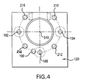
- FIG. 4 is an aft view of the block 120 showing the hole 188.
- FIG. 4 further shows additional holes 190, 192, and 194 of like size and at like radius from the axis 510.
- the exemplary holes 186, 188, 190, 192, and 194 are unthreaded.
- the block 120 may be rotated about the axis 510 relative to the upright 78.
- This rotation may be of both blocks 120 and 102, their mounted jaws 50 and 52, and the blade 22 as a unit.
- the rotation may bring any of the holes 188, 190, 192, and 194 into alignment with the hole 186 of FIG. 2.
- the holes 192 and 194 may represent respective 90 degree rotations of the block counterclockwise and clockwise, respectively as viewed in FIG. 4.
- the hole 190 may be at a different angle.
- An exemplary angle involves a counterclockwise rotation of 17°30' which facilitates marking on the underside 196 (FIG. 2) of a platform tongue 198.
- Such tongues are common blade features having undersides within a few degrees of the exemplary underside orientation.
- the 17°30' angle is a good approximation, allowing the fixture to be used for a variety of blades.
- the exemplary locking members 182 are cap screws (e.g., hex-head).
- the shafts of these cap screws pass through slots 200 (FIG. 5) in the upright 78.
- the exemplary slots 200 are formed essentially as annular segments of slightly more than 90 degree extent about the axis 510.
- Each of the slots 200 has a pair of circumferential ends 202 which determine ends of a rotational range of motion with the screws 182 installed in a given set of corresponding holes in the block 120.
- FIG. 4 shows four such corresponding holes 210, 212, 214, and 216 evenly spaced about the axis 510 exactly out of phase with the holes 188, 192, and 194.
- these holes 210, 212, 214, and 216 are threaded to receive the shafts of the screws 182. Accordingly, when these screws 182 are tightened, the block 120 is firmly secured to the upright 78. By changing the particular pair of these holes engaged by the screws 182, a full range of rotation about the axis 510 may be obtained subject to the lockouts provided by the pin 180.
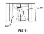
- the exemplary jaws 50 and 52 of FIG. 4 are each assemblies of a metallic structural member 250 and 252 with a polymeric blade-engaging member 254 and 256.
- the exemplary structural members 250 and 252 are identical to each other.
- the blade-engaging members have internal surfaces 258 and 260 for engaging the blade. These surfaces 258 and 260 include respective convex and concave portions generally complementary to the pressure and suction sides 270 and 280 of the airfoil.
- the exemplary polymeric members 254 and 256 are heat bonded to their associated metallic members 250 and 252.
- FIGS. 2 and 6 further show a pair of pins 280 press fit in bores 282 in the polymeric member 256 and slidingly extending into bores 284 in the mating polymeric member 254.
- the pins 280 serve an alignment function. As the jaw 52 is driven in the direction 512, there is a degree of float in the mounting of the block 102 to the screw 94. Engagement of the pins 280 with the bores 284 provides proper alignment of the two jaws 50 and 52 as the jaws are closed around the blade.
- the fixture In operation, the fixture is installed to the base and remains fixed. To mark a blade, the operator installs the jaws for that blade if they are not already installed. The operator then inserts the blade and clamps the jaws. The operator then orients the desired marking site in the marking orientation. The operator then manually or semi-manually brings the head to the correct height (e.g., so that the tip is at the appropriate height). In this height the tip may be slightly above the marking site, height but has a reciprocal range of motion effective to provide the indentation. Then, under automatic control, the marker provides the desired marking. This may involve motors in the head moving the tip to a given location along the site, indenting to provide a first indentation or pixel, moving the tip transversely to the location of the next pixel and so on.
- an articulating fixture may have several advantages. First, for processing any given part configuration (e.g., a given blade) only a single pair of jaws are required. This may be distinguished from several fixtures for each part configuration. This reduction saves cost and changeover time. Furthermore, large scale processing may be facilitated. The parts may be installed to the associated jaw pairs without reference to which site on the part will ultimately be marked. Then the fixture may be articulated to bring the desired unmarked marking site into the proper position and orientation. The need to change fixtures for different parts is also reduced or eliminated.
- any given part configuration e.g., a given blade
Landscapes
- Engineering & Computer Science (AREA)
- Mechanical Engineering (AREA)
- Jigs For Machine Tools (AREA)
- Structures Of Non-Positive Displacement Pumps (AREA)
- Turbine Rotor Nozzle Sealing (AREA)
Abstract
Description
- The invention relates to the manufacture and repair of turbine engine components. More particularly, the invention relates to the identification marking of turbine engine elements.
- Identification marking of turbine engine components has drawn much recent attention. Although the purposes and uses of such marking may vary, key examples are seen during engine manufacture, repair and, more particularly, engine component repair. It has become standard practice for some manufacturers and repair/refurbishing operations to mark each component as it is received for repair or refurbishing. The markings may be identification markings (e.g., operator-readable alphanumeric serial markings or machine-readable codes (e.g., 2-d dot matrix codes)). The markings may, themselves, contain further information (e.g., date/time of repair, place of repair, repair kind code, or the like) or such information may be stored in a database accessible based upon the markings.
- An exemplary marking technique is dot peen indentation marking. Other techniques include laser and/or chemical etching. Dot peen marking has advantages of speed, low cost, and an extreme degree of robustness.
- Typical components have a limited portion of surface area suitable for marking. For example, the airfoils of turbine and compressor blades may be off-limits as may other surfaces exposed to the gas path or to high stresses. For such blades, marking at particular locations along the blade platform underside and/or the ends of the blade attachment root may be appropriate. Thus, for a given component, a manufacturer may specify a finite number of accepted marking locations/sites.
- With typical marking apparatus, the marking location on the component must have a predetermined spatial relationship to a marking head (i.e., the location must be in an operative marking position). Custom fixtures may be used to hold the components. For example, due to different airfoil and other shapes, different fixtures may be required to hold airfoils of each blade stage in the engine. Staying with the example of blades, the fixtures may have surfaces complementary to the particular shape of the airfoils of the associated stage. A given fixture positions a given one of the permitted locations in the operative marking position. To address the various permitted locations, multiple fixtures may be required for the given component, which is expensive and accommodates valuable work cell space.
- Thus, to mark the components as they come in or go out, an operator must inspect each component to see which permitted location(s) have not already been marked. The operator then selects the appropriate unmarked location and selects the fixture or adapter for that specific location from the various fixtures/adapters for that specific component.
- One aspect of the invention involves a system including a fixture having a base and means for receiving a pair of jaws in an installed condition. The fixture includes means for articulating the installed jaws relative to the base with at least first and second rotational degrees of freedom. A pair of the jaws (e.g., a first of several pairs) includes a first jaw having a surface portion generally concave and complementary to a suction side portion of an airfoil of a first turbine engine element. A second jaw has a surface portion generally convex and complementary to a pressure side portion of the airfoil.
- In various implementations, there may be additional sets of jaw pairs, each having first and second jaws whose surface portions are complementary to suction and pressure sides of different airfoils from different turbine engine elements. The means for articulating may further provide articulation in a third rotational degree of freedom.
- The apparatus may be used in a marking operation. For example, the first turbine engine element may be received and installed to the first pair of jaws. The first pair of jaws may be installed to the fixture. A first marking site may be selected on the first turbine engine element. The fixture may be articulated to bring the first marking site to a first spatial relationship with a marking device. The marking device may be used to mark the first marking site.
- The details of one or more embodiments of the invention are set forth in the accompanying drawings and the description below. Other features of the invention will be apparent from the description and drawings, and from the claims.
-
- FIG. 1 is a view of a marking station.
- FIG. 2 is a side view of a fixture of the station of FIG. 1.
- FIG. 3 is a front view of the fixture of FIG. 2.
- FIG. 4 is a back view of a back mounting block of the fixture of FIG. 2.
- FIG. 5 is a back view of an upper portion of a back upright of the fixture of FIG. 2.
- FIG. 6 is a isolated bottom view of a mated jaw pair of the fixture of FIG. 2.
- Like reference numbers and designations in the various drawings indicate like elements.
- FIG. 1 shows a
marking station 20 for marking ablade 22. Theexemplary station 20 includes a marking apparatus orhead 24 such as a dot-peen marker. Theblade 22 is held in afixture assembly 26. Theexemplary fixture 26, is, in turn, mounted to the upper surface ortop 28 of abase 30 of the station. Thehead 24 may be mounted relative to thebase 30 such as by anarm structure 32. Theexemplary head 24 may be vertically movable along the arm under computer control. The exemplary head carries amarking bit 34 with alower marking tip 36. The head or the bit may be movable horizontally under computer control. For example, the bit may be movable fore and aft (away from and toward the arm) and left and right by motors (not shown) in the head. - FIG. 2 shows further details of the
blade 22 andfixture 26. The blade has anairfoil 40 extending outboard from a root 42 to atip 44. The airfoil base 42 is attached to a platform 45 (e.g., unitarily formed therewith). Anattachment root 46 extends from the inboard end of theplatform 45 to aterminus 48. Theexemplary root 46 has a convoluted "fir tree" profile for mating with a complementary slot in a disk (not shown) to secure the blade to the disk. Theblade 22 is held betweenremovable jaw elements fixture 26. - The
exemplary fixture 26 is a vise mechanism having afixture base 60. Theexemplary base 60 may be mounted to the station base 30 (e.g., with anunderside 62 of thebase 60 contacting thetop 28 and secured thereto by means offasteners 64. Theupper surface 66 of thebase 60 includes aconcave surface 68. In theexemplary fixture 26, thesurface 68 is singly concave having an essentially fixed radius of curvature R1. An axis 500 (FIG. 3) of said curvature is nearterminus 48. An exemplary R1 is 0.3m, more broadly 0.1-2.0m or 0.2-0.6m. Thesurface 68 is engaged by a complementaryconvex surface 70 of a fixturemain body 72. Themain body 72 includes abase portion 74 along which thesurface 70 is formed. Themain body 72 includes fore and aftupright structures main body base 74. - The
main body 72 serves as the body of a vise or clamping structure to which thejaws exemplary fixture 26, thefore upright 76 serves as a screw carrier having an internally threadedportion 90 along a screw axis 510 (FIG. 3). The internally threadedportion 90 threadingly receives an externally threadedbody 92 of ascrew 94. At anoutboard end 96, thescrew 94 is engaged to ahandle 98 and secured thereto against relative rotation about theaxis 510. At an inboard end 100, thescrew 94 engages amounting block 102. The mountingblock 102 acts as a movable jaw carrying theinsert 52. In theexemplary fixture 26, aforward flange 110 of thejaw 52 sits atop anupper surface 112 of theblock 102 and is secured thereto by one ormore screws 114. The connection of thescrew 94 to theblock 102 advantageously permits relative rotation about theaxis 510 so that the block may maintain its orientation as it translates along theaxis 510. However, the connection advantageously permits transmission of force along theaxis 510 at least in adirection 512 moving theblock 102 toward thejaw 50. Rotation of the handle in a direction 514 (FIG. 3) about theaxis 510 drives theblock 102 andjaw 52 in thedirection 512. Opposite rotation moves them in an opposite direction. Thejaw 50 may similarly be mounted to anaft mounting block 120 carried by theaft upright structure 78. Mounting of theblock 120 to theupright structure 78 advantageously permits a lockable relative rotation about the axis 510 (e.g., as is discussed below). - FIG. 2 shows exemplary means for providing the lockable relative rotation about the
axis 500. One ormore locking members 150 selectively lock themain body base 74 to thefixture base 60. Theexemplary locking members 150 are formed as screws (e.g., a transverse array of threescrews 150 shown in FIG. 3). Each of theexemplary screws 150 passes through an associatedhole 152 in thebody base 74. In an inserted condition, the screws may further extend into one of an associated group ofholes fixture base 60. In an exemplary embodiment, thehole 152 is unthreaded whereas theholes screw 150. With the screws disengaged (i.e., out of theholes 154, 156, and 158) thefixture body 72 may be rotated about theaxis 500 to bring thehole 152 into alignment with one of theholes axis 510 is horizontal). Thehole 156 corresponds to a slightly inclined orientation (e.g., with theaxis 510 rotated counterclockwise by about 5° as viewed in FIG. 2. Thehole 158 corresponds with a declined orientation (e.g., theaxis 510 rotated clockwise by about 20° as viewed in FIG. 2). For example, with theterminus 48 faceted, the identified rotations can bring each of the facets into the operative position and appropriate orientation (e.g., horizontal). The marking site need not be exactly horizontal. For small transverse marker excursions (e.g., up to about 6 mm) small off-horizontal angles (e.g., up to about 5°) may be acceptable (i.e., the maker can still effectively mark , especially if the head height is fixed). The smaller such angle, the greater the permitted transverse excursion (e.g., dimension of the marking). - FIG. 2 shows further details of the means for providing lockable rotation of the jaws and blade relative to the
fixture body 72 about theaxis 510. In theexemplary fixture 26, theblock 120 has acircular boss 170 received in acircular aperture 172 in the upright 78 centered on theaxis 510. Sliding interaction of theboss 170 and surface of theaperture 172 guide the relative rotation about theaxis 510. The rotation may be locked by locking means. Exemplary locking means include one ormore locking members exemplary locking member 180 is formed as a pin. An exemplary pin is shown having a spring-loadedball detent 184 for detent locking the pin in an inserted position extending through apertures or holes in theupright 78 and block 120. Anexemplary hole 186 is shown in theblock 78. FIG. 2 also shows anexemplary hole 188 in theblock 120. FIG. 4 is an aft view of theblock 120 showing thehole 188. FIG. 4 further showsadditional holes axis 510. Theexemplary holes - With the locking
members block 120 may be rotated about theaxis 510 relative to theupright 78. This rotation may be of bothblocks mounted jaws blade 22 as a unit. The rotation may bring any of theholes hole 186 of FIG. 2. For example, relative to thehole 188, theholes platform tongue 198. Such tongues are common blade features having undersides within a few degrees of the exemplary underside orientation. Thus the 17°30' angle is a good approximation, allowing the fixture to be used for a variety of blades. - The
exemplary locking members 182 are cap screws (e.g., hex-head). In theexemplary fixture 26, the shafts of these cap screws pass through slots 200 (FIG. 5) in theupright 78. Theexemplary slots 200 are formed essentially as annular segments of slightly more than 90 degree extent about theaxis 510. Each of theslots 200 has a pair of circumferential ends 202 which determine ends of a rotational range of motion with thescrews 182 installed in a given set of corresponding holes in theblock 120. FIG. 4 shows four suchcorresponding holes axis 510 exactly out of phase with theholes holes screws 182. Accordingly, when thesescrews 182 are tightened, theblock 120 is firmly secured to theupright 78. By changing the particular pair of these holes engaged by thescrews 182, a full range of rotation about theaxis 510 may be obtained subject to the lockouts provided by thepin 180. - The
exemplary jaws structural member member structural members internal surfaces surfaces suction sides exemplary polymeric members metallic members pins 280 press fit inbores 282 in thepolymeric member 256 and slidingly extending intobores 284 in themating polymeric member 254. Thepins 280 serve an alignment function. As thejaw 52 is driven in thedirection 512, there is a degree of float in the mounting of theblock 102 to thescrew 94. Engagement of thepins 280 with thebores 284 provides proper alignment of the twojaws - In operation, the fixture is installed to the base and remains fixed. To mark a blade, the operator installs the jaws for that blade if they are not already installed. The operator then inserts the blade and clamps the jaws. The operator then orients the desired marking site in the marking orientation. The operator then manually or semi-manually brings the head to the correct height (e.g., so that the tip is at the appropriate height). In this height the tip may be slightly above the marking site, height but has a reciprocal range of motion effective to provide the indentation. Then, under automatic control, the marker provides the desired marking. This may involve motors in the head moving the tip to a given location along the site, indenting to provide a first indentation or pixel, moving the tip transversely to the location of the next pixel and so on.
- The use of an articulating fixture may have several advantages. First, for processing any given part configuration (e.g., a given blade) only a single pair of jaws are required. this may be distinguished from several fixtures for each part configuration. This reduction saves cost and changeover time. Furthermore, large scale processing may be facilitated. The parts may be installed to the associated jaw pairs without reference to which site on the part will ultimately be marked. Then the fixture may be articulated to bring the desired unmarked marking site into the proper position and orientation. The need to change fixtures for different parts is also reduced or eliminated.
- One or more embodiments of the present invention have been described. Nevertheless, it will be understood that various modifications may be made without departing from the scope of the invention. For example, details of the particular parts and the particular marking apparatus used may influence details of any particular implementation. Accordingly, other embodiments are within the scope of the following claims.
Claims (20)
- An apparatus (24) comprising:a fixture (26) having;a base (60);means for receiving a pair of jaws (50,52) in an installed condition; andmeans for articulating the installed jaws (50,52) relative to the base (60) with at least first and second rotational degrees of freedom; andat least a first pair of said jaws comprising:a first jaw (50) having a surface portion (258) generally concave and complementary to a suction side portion (280) of an airfoil (40) of a first turbine engine element;a second jaw (52) having a surface portion (260) generally convex and complementary to a pressure side portion (270) of an airfoil (40) of said first turbine engine element.
- The apparatus of claim 1 further comprising:a dot peen marker positioned to mark the first turbine element.
- The apparatus of claim 1 or 2 further comprising:at least one additional pair of jaws (50,52) having:a first jaw (50) having a surface portion (258) generally concave and complementary to a suction side portion (280) of an airfoil (40) of another turbine engine element, different in form from the first turbine engine element;a second jaw (52) having a surface portion (260) generally convex and complementary to a pressure side portion (270) of an airfoil (40) of said another turbine engine element.
- The apparatus of claim 1, 2 or 3 further comprising:a plurality of additional pairs of jaws (50,52), each having:a first jaw (50) having a surface portion (258) generally concave and complementary to a suction side portion (280) of an airfoil (40) of an associated turbine engine element, different in form from the other turbine engine elements; anda second jaw (52) having a surface portion (260) generally convex and complementary to a pressure side portion (270) of an airfoil of said associated turbine engine element.
- The apparatus of any preceding claim wherein:the means for articulating includes means (150, 180, 182) for locking the first and second rotational degrees of freedom.
- The apparatus of any preceding claim wherein:the means for articulating provides no additional rotational degree of freedom.
- The apparatus of any preceding claim wherein:the first rotational degree of freedom is about a first axis (510) extending through the first and second jaws (50,52); andthe second rotational degree of freedom is about a second axis (500) beyond the first and second jaws (50,52) and orthogonal to but not intersecting the first axis (510).
- The apparatus of any preceding claim wherein:the means for receiving comprise:a first mounting block (102) for receiving the first jaw (50) and directly lockably held for lockable rotation about a first axis (510); anda second mounting block (120) for receiving the second jaw (52) and directly lockably held for lockable rotation about said first axis (510); andthe apparatus further comprises means (96) for translating the second block (102) along the first axis toward the first block (120).
- The apparatus of claim 8 wherein:the first rotational degree of freedom consists essentially of rotation about the first axis (510).
- A method for using the apparatus of any preceding claim comprising:receiving said first turbine engine element;installing the first pair of jaws (50,52) to the fixture; installing said first turbine engine element to the first pair of jaws (50,52);selecting a first marking site on the first turbine engine element;articulating the fixture (26) to bring the first marking site to a first spatial relationship with a marking device (36); andmarking the first marking site using the marking device (36).
- The method of claim 10 wherein the selecting is from a predetermined group of marking sites and includes excluding at least one already-marked site from said group.
- The method of claim 10 or 11 wherein the first marking site is on a root portion (46) of the first turbine engine element.
- The method of claim 10, 11 or 12 wherein the marking comprises dot peen marking.
- The method of any of claims 10 to 13 wherein:the first turbine engine element is a blade (22) and the first marking site is on an attachment root (46) of the blade (22).
- The method of any of claims 10 to 14 further comprising
receiving a second turbine engine element (22) different in form from the first turbine engine element (22);
installing a second pair of jaws (50,52), different in from the first pair of jaws, to the fixture;
installing said second turbine engine element (22) to the second pair of jaws (50,52);
selecting a first marking site on the second turbine engine element (22), optionally similar to the first marking site on the first turbine engine element (22);
articulating the fixture (26) to bring the first marking site on the second turbine engine element (22) to said first spatial relationship with a marking device (36); and
marking the first marking site on the second turbine engine element (22) using the marking device (36). - An apparatus (24) for marking a turbine element (22) comprising:a marker (36); anda fixture (26) having:a fixture base (60);a first jaw (50) having a surface portion (258) engaging a first portion of the turbine engine element (22) in an engaged condition;a second jaw (52) having a surface portion (260) engaging a second portion of the turbine engine element (22) in the engaged condition;a fixture body (72) carrying the first and second jaws (50,52) rotatably about a first axis (510) and carried by the fixture base (60) rotatably about a second axis (500).
- The apparatus of claim 16 wherein:the marker (36) is a dot peen marker.
- The apparatus of claim 16 or 17 wherein:the fixture base (60) has an upwardly concave surface (68) with the second axis (500) as an axis of curvature; andthe fixture body (72) has a downwardly convex surface (70) with the second axis (500) as an axis of curvature.
- The apparatus of claim 16, 17 or 18 wherein:the fixture body carries the second jaw (52) by a jack screw (94) rotatable in a first direction about the first axis (510) to drive the second jaw (52) toward the first jaw (50).
- The apparatus of any of claims 16 to 19 wherein:at least one alignment pin (280) is carried by one of the first and second jaws (50,52) for engaging a hole (282,284) in the other of said first and second jaws (50,52).
Priority Applications (1)
| Application Number | Priority Date | Filing Date | Title |
|---|---|---|---|
| EP11171575.1A EP2374576B1 (en) | 2005-06-30 | 2006-06-29 | Marking figures and methods |
Applications Claiming Priority (1)
| Application Number | Priority Date | Filing Date | Title |
|---|---|---|---|
| US11/173,867 US7178254B2 (en) | 2005-06-30 | 2005-06-30 | Marking fixtures and methods |
Related Child Applications (1)
| Application Number | Title | Priority Date | Filing Date |
|---|---|---|---|
| EP11171575.1 Division-Into | 2011-06-27 |
Publications (3)
| Publication Number | Publication Date |
|---|---|
| EP1738874A2 true EP1738874A2 (en) | 2007-01-03 |
| EP1738874A3 EP1738874A3 (en) | 2008-11-12 |
| EP1738874B1 EP1738874B1 (en) | 2012-05-30 |
Family
ID=37056550
Family Applications (2)
| Application Number | Title | Priority Date | Filing Date |
|---|---|---|---|
| EP11171575.1A Ceased EP2374576B1 (en) | 2005-06-30 | 2006-06-29 | Marking figures and methods |
| EP06253419A Ceased EP1738874B1 (en) | 2005-06-30 | 2006-06-29 | Apparatus and method for marking of turbine blades |
Family Applications Before (1)
| Application Number | Title | Priority Date | Filing Date |
|---|---|---|---|
| EP11171575.1A Ceased EP2374576B1 (en) | 2005-06-30 | 2006-06-29 | Marking figures and methods |
Country Status (3)
| Country | Link |
|---|---|
| US (1) | US7178254B2 (en) |
| EP (2) | EP2374576B1 (en) |
| JP (1) | JP4394094B2 (en) |
Cited By (3)
| Publication number | Priority date | Publication date | Assignee | Title |
|---|---|---|---|---|
| EP1927416A1 (en) * | 2006-11-17 | 2008-06-04 | Siemens Aktiengesellschaft | Process of manufacturing a casting with a marking, casted part and group of castings |
| CN113618127A (en) * | 2021-08-20 | 2021-11-09 | 中国航发航空科技股份有限公司 | Machining process of aero-engine blade |
| FR3150726A1 (en) * | 2023-07-03 | 2025-01-10 | Safran Aircraft Engines | SYSTEM FOR BRIDLING A DAWN FOOT |
Families Citing this family (11)
| Publication number | Priority date | Publication date | Assignee | Title |
|---|---|---|---|---|
| US7597762B2 (en) * | 2005-09-21 | 2009-10-06 | General Electric Company | Methods and apparatus for manufacturing components |
| US7752755B2 (en) * | 2005-10-14 | 2010-07-13 | General Electric Company | Methods and apparatus for manufacturing components |
| ITMI20071206A1 (en) * | 2007-06-15 | 2008-12-16 | Ansaldo Energia Spa | TOOL AND METHOD OF LOCKING A SHOVEL OF A TURBINE |
| JP5839963B2 (en) * | 2011-11-29 | 2016-01-06 | 三菱日立パワーシステムズ株式会社 | Turbine blade and turbine |
| FR2989610B1 (en) * | 2012-04-24 | 2015-03-20 | Snecma | MACHINING MACHINE FOR TURBOMACHINE MOBILE DRAWING |
| SG2013002183A (en) * | 2013-01-10 | 2014-08-28 | Pratt & Whitney Services Pte Ltd | Turbine shroud milling with blade held in same fixture during milling of concave and convex parts |
| US9840926B2 (en) | 2013-07-10 | 2017-12-12 | United Technologies Corporation | Abrasive flow media fixture with end contour |
| DE102013224358A1 (en) * | 2013-11-28 | 2015-05-28 | Airbus Operations Gmbh | Method for measuring large components |
| CN108145325A (en) * | 2017-12-08 | 2018-06-12 | 中国航发动力股份有限公司 | A fixture and a method for machining small holes in a semi-closed narrow cavity based on the fixture |
| RU192261U1 (en) * | 2019-01-16 | 2019-09-11 | Публичное акционерное общество "Уфимское моторостроительное производственное объединение" (ПАО "ОДК-УМПО") | CLAMP |
| CN115026347B (en) * | 2022-06-23 | 2024-03-29 | 中国航发贵州黎阳航空动力有限公司 | Processing method of slender tenon tooth of blade and clamp for broaching slender tenon tooth |
Citations (2)
| Publication number | Priority date | Publication date | Assignee | Title |
|---|---|---|---|---|
| EP1215012A2 (en) | 2000-12-16 | 2002-06-19 | Blohm Maschinenbau GmbH | Workpiece holder for grinding machine |
| GB2387433A (en) | 2002-04-08 | 2003-10-15 | Edward Pryor And Son Ltd | Integrated marking system with optical verification camera |
Family Cites Families (7)
| Publication number | Priority date | Publication date | Assignee | Title |
|---|---|---|---|---|
| NZ220849A (en) * | 1986-06-30 | 1989-03-29 | Dowell Australia | Set of jaws for holding extruded aluminium sections during machining |
| US5427478A (en) * | 1993-09-30 | 1995-06-27 | John N. Boucher | Bowling ball drilling apparatus |
| GB9402724D0 (en) * | 1994-02-11 | 1994-04-06 | Muldrew Robert J | Multi angle mounting device |
| US6135022A (en) * | 1997-09-09 | 2000-10-24 | Troester; Thomas A. | Lightweight marking device |
| US6705019B2 (en) * | 2001-02-08 | 2004-03-16 | George Mauro | Goniometer |
| CH695097A5 (en) * | 2001-09-13 | 2005-12-15 | Hemo Werkzeugbau Dieter Mosig | Numerical controlled machine has secondary clamping plates for delicate components |
| US20030221470A1 (en) * | 2002-05-30 | 2003-12-04 | Gunther Siegel | Apparatus for writing in metal |
-
2005
- 2005-06-30 US US11/173,867 patent/US7178254B2/en not_active Expired - Lifetime
-
2006
- 2006-06-29 EP EP11171575.1A patent/EP2374576B1/en not_active Ceased
- 2006-06-29 JP JP2006178909A patent/JP4394094B2/en not_active Expired - Fee Related
- 2006-06-29 EP EP06253419A patent/EP1738874B1/en not_active Ceased
Patent Citations (2)
| Publication number | Priority date | Publication date | Assignee | Title |
|---|---|---|---|---|
| EP1215012A2 (en) | 2000-12-16 | 2002-06-19 | Blohm Maschinenbau GmbH | Workpiece holder for grinding machine |
| GB2387433A (en) | 2002-04-08 | 2003-10-15 | Edward Pryor And Son Ltd | Integrated marking system with optical verification camera |
Cited By (3)
| Publication number | Priority date | Publication date | Assignee | Title |
|---|---|---|---|---|
| EP1927416A1 (en) * | 2006-11-17 | 2008-06-04 | Siemens Aktiengesellschaft | Process of manufacturing a casting with a marking, casted part and group of castings |
| CN113618127A (en) * | 2021-08-20 | 2021-11-09 | 中国航发航空科技股份有限公司 | Machining process of aero-engine blade |
| FR3150726A1 (en) * | 2023-07-03 | 2025-01-10 | Safran Aircraft Engines | SYSTEM FOR BRIDLING A DAWN FOOT |
Also Published As
| Publication number | Publication date |
|---|---|
| EP1738874B1 (en) | 2012-05-30 |
| EP2374576B1 (en) | 2013-06-05 |
| JP2007009913A (en) | 2007-01-18 |
| JP4394094B2 (en) | 2010-01-06 |
| US7178254B2 (en) | 2007-02-20 |
| EP1738874A3 (en) | 2008-11-12 |
| EP2374576A1 (en) | 2011-10-12 |
| US20070006475A1 (en) | 2007-01-11 |
Similar Documents
| Publication | Publication Date | Title |
|---|---|---|
| EP1738874B1 (en) | Apparatus and method for marking of turbine blades | |
| CN100574986C (en) | Power tools and optical alignment systems for power tools | |
| US7900898B2 (en) | Method and apparatus for fixturing a panel | |
| EP1452275B1 (en) | Apparatus for consistently retaining a gas turbine engine blade in a predetermined position and orientation | |
| EP0237156B1 (en) | Turbine blade holding device | |
| EP1338378B1 (en) | Fixture for locating and clamping a part for laser drilling | |
| US6374878B1 (en) | Portable fixture for woodworking tools | |
| US5921534A (en) | Detachable jaw for vise-like workholding apparatus | |
| US20170292812A1 (en) | Sight adjustment tool | |
| EP1408301A2 (en) | Methods and apparatus for aligning components for inspection | |
| CN1727140A (en) | Jig apparatus | |
| CN104198778A (en) | Automated multi-point probe manipulation | |
| EP0739683A1 (en) | Workpiece holder, particularly adapted for holding eyeglasses lenses | |
| US20090193864A1 (en) | Repeatable bender angle apparatus | |
| US4726576A (en) | Work supporting device | |
| US6768076B2 (en) | Precision base and fixture adapter set-up | |
| KR19990071503A (en) | Workpiece cutting device with couplings that are dynamic cutting | |
| US20200198022A1 (en) | Wheel rim chuck with soft jaws | |
| EP1403003A2 (en) | Methods and apparatus for securing components for manufacture | |
| US4538946A (en) | Hand repair tool for curved surfaces | |
| US20070056180A1 (en) | Methods and apparatus for manufacturing components | |
| CN116183106B (en) | A general-purpose blade weight moment measuring fixture | |
| US7972221B2 (en) | Method of spherical object orientation and orienter for the same | |
| CN111336960A (en) | Adjustable fixture for positioning parts for dimensional measurement | |
| JP2025540915A (en) | Build Platform Systems for Additive Manufacturing |
Legal Events
| Date | Code | Title | Description |
|---|---|---|---|
| PUAI | Public reference made under article 153(3) epc to a published international application that has entered the european phase |
Free format text: ORIGINAL CODE: 0009012 |
|
| AK | Designated contracting states |
Kind code of ref document: A2 Designated state(s): AT BE BG CH CY CZ DE DK EE ES FI FR GB GR HU IE IS IT LI LT LU LV MC NL PL PT RO SE SI SK TR |
|
| AX | Request for extension of the european patent |
Extension state: AL BA HR MK YU |
|
| PUAL | Search report despatched |
Free format text: ORIGINAL CODE: 0009013 |
|
| AK | Designated contracting states |
Kind code of ref document: A3 Designated state(s): AT BE BG CH CY CZ DE DK EE ES FI FR GB GR HU IE IS IT LI LT LU LV MC NL PL PT RO SE SI SK TR |
|
| AX | Request for extension of the european patent |
Extension state: AL BA HR MK RS |
|
| 17P | Request for examination filed |
Effective date: 20090512 |
|
| 17Q | First examination report despatched |
Effective date: 20090615 |
|
| AKX | Designation fees paid |
Designated state(s): DE GB |
|
| DAC | Divisional application: reference to earlier application (deleted) | ||
| GRAP | Despatch of communication of intention to grant a patent |
Free format text: ORIGINAL CODE: EPIDOSNIGR1 |
|
| GRAC | Information related to communication of intention to grant a patent modified |
Free format text: ORIGINAL CODE: EPIDOSCIGR1 |
|
| GRAS | Grant fee paid |
Free format text: ORIGINAL CODE: EPIDOSNIGR3 |
|
| GRAA | (expected) grant |
Free format text: ORIGINAL CODE: 0009210 |
|
| AK | Designated contracting states |
Kind code of ref document: B1 Designated state(s): DE GB |
|
| REG | Reference to a national code |
Ref country code: GB Ref legal event code: FG4D |
|
| REG | Reference to a national code |
Ref country code: DE Ref legal event code: R081 Ref document number: 602006029780 Country of ref document: DE Owner name: UNITED TECHNOLOGIES CORP. (N.D.GES.D. STAATES , US Free format text: FORMER OWNER: UNITED TECHNOLOGIES CORP. (N.D.GES.D. STAATES DELAWARE), HARTFORD, CONN., US |
|
| REG | Reference to a national code |
Ref country code: DE Ref legal event code: R096 Ref document number: 602006029780 Country of ref document: DE Effective date: 20120802 |
|
| PLBE | No opposition filed within time limit |
Free format text: ORIGINAL CODE: 0009261 |
|
| STAA | Information on the status of an ep patent application or granted ep patent |
Free format text: STATUS: NO OPPOSITION FILED WITHIN TIME LIMIT |
|
| 26N | No opposition filed |
Effective date: 20130301 |
|
| REG | Reference to a national code |
Ref country code: DE Ref legal event code: R097 Ref document number: 602006029780 Country of ref document: DE Effective date: 20130301 |
|
| REG | Reference to a national code |
Ref country code: DE Ref legal event code: R082 Ref document number: 602006029780 Country of ref document: DE Representative=s name: SCHMITT-NILSON SCHRAUD WAIBEL WOHLFROM PATENTA, DE |
|
| REG | Reference to a national code |
Ref country code: DE Ref legal event code: R082 Ref document number: 602006029780 Country of ref document: DE Representative=s name: SCHMITT-NILSON SCHRAUD WAIBEL WOHLFROM PATENTA, DE Ref country code: DE Ref legal event code: R081 Ref document number: 602006029780 Country of ref document: DE Owner name: UNITED TECHNOLOGIES CORP. (N.D.GES.D. STAATES , US Free format text: FORMER OWNER: UNITED TECHNOLOGIES CORPORATION, HARTFORD, CONN., US |
|
| PGFP | Annual fee paid to national office [announced via postgrant information from national office to epo] |
Ref country code: DE Payment date: 20190521 Year of fee payment: 14 |
|
| REG | Reference to a national code |
Ref country code: DE Ref legal event code: R119 Ref document number: 602006029780 Country of ref document: DE |
|
| PG25 | Lapsed in a contracting state [announced via postgrant information from national office to epo] |
Ref country code: DE Free format text: LAPSE BECAUSE OF NON-PAYMENT OF DUE FEES Effective date: 20210101 |
|
| PGFP | Annual fee paid to national office [announced via postgrant information from national office to epo] |
Ref country code: GB Payment date: 20240521 Year of fee payment: 19 |
|
| GBPC | Gb: european patent ceased through non-payment of renewal fee |
Effective date: 20250629 |
|
| PG25 | Lapsed in a contracting state [announced via postgrant information from national office to epo] |
Ref country code: GB Free format text: LAPSE BECAUSE OF NON-PAYMENT OF DUE FEES Effective date: 20250629 |