EP1736745B1 - Verfahren zur adaptiven Korrektur von Drifterscheinungen bei einer Kraftmessvorrichtung sowie eine Kraftmessvorrichtung zur Durchführung des Verfahrens. - Google Patents
Verfahren zur adaptiven Korrektur von Drifterscheinungen bei einer Kraftmessvorrichtung sowie eine Kraftmessvorrichtung zur Durchführung des Verfahrens. Download PDFInfo
- Publication number
- EP1736745B1 EP1736745B1 EP05105422A EP05105422A EP1736745B1 EP 1736745 B1 EP1736745 B1 EP 1736745B1 EP 05105422 A EP05105422 A EP 05105422A EP 05105422 A EP05105422 A EP 05105422A EP 1736745 B1 EP1736745 B1 EP 1736745B1
- Authority
- EP
- European Patent Office
- Prior art keywords
- drift
- signal
- measuring device
- stored
- measuring
- Prior art date
- Legal status (The legal status is an assumption and is not a legal conclusion. Google has not performed a legal analysis and makes no representation as to the accuracy of the status listed.)
- Expired - Lifetime
Links
Images


Classifications
-
- G—PHYSICS
- G01—MEASURING; TESTING
- G01G—WEIGHING
- G01G3/00—Weighing apparatus characterised by the use of elastically-deformable members, e.g. spring balances
- G01G3/12—Weighing apparatus characterised by the use of elastically-deformable members, e.g. spring balances wherein the weighing element is in the form of a solid body stressed by pressure or tension during weighing
- G01G3/14—Weighing apparatus characterised by the use of elastically-deformable members, e.g. spring balances wherein the weighing element is in the form of a solid body stressed by pressure or tension during weighing measuring variations of electrical resistance
- G01G3/1414—Arrangements for correcting or for compensating for unwanted effects
-
- G—PHYSICS
- G01—MEASURING; TESTING
- G01G—WEIGHING
- G01G23/00—Auxiliary devices for weighing apparatus
- G01G23/01—Testing or calibrating of weighing apparatus
Definitions
- the invention relates to a method for correcting drift phenomena in an electronic force measuring device, in particular a balance, and to a force measuring device suitable for carrying out this method, in particular a balance, according to the preamble of patent claims 1 and 12, respectively.
- Disturbing drift phenomena in particular the so-called creep, i.
- the change in the measurement result within one measurement interval is still a topic despite significant improvements in the properties of the elements relevant to the precision of the scales.
- the US 4,656,599 is concerned with the detection of the influences on the measuring transducer of a balance disturbing influences. These include temperature, moisture and creep.
- a memory area is present, to which digital data are continuously supplied from the output signals of respective sensors and possibly the output signal of the measuring sensor and stored there for a predetermined time. The data derived from different times are evaluated with predetermined weighting factors and used to determine the corrections to be applied to the output signal of the transducer
- the status of the "creep" is calculated on this scale based on constants that were determined and stored during the initial setting of the balance.
- the individual determination of these constants for each balance is necessary according to [4], as deviations between different scales are usually present.
- the object of the present invention is therefore to provide an improved method for correcting drift phenomena in an electronic force measuring device, in particular a balance, and a force measuring device, in particular a balance, working according to this improved method.
- the inventive method is used to correct Drifterscheinitch based on the creep, in an electronic
- Force measuring device in particular a balance, which has a measuring transducer, by means of which a load acting measurement signal is formed, which is supplied via an analog-to-digital converter of at least one processor-based, the processing of digital signals serving digital signal processing unit can be compensated by the drift deviations and which accesses by means of the processor stored in a memory unit drift parameters, based on which a time-dependent correction value is calculated and thus the drift error of the measurement signal is corrected.
- new, optimized values for the drift parameters of the drift error of the measurement signal caused by creep are automatically determined on the basis of an optimization program stored in the memory unit within regular or irregular time intervals, automatically or by the user Storage unit filed.
- Uncorrected or only partially corrected signal waveforms of the measurement signal are stored when measurements are taken during test operations and / or during calibration operations linked to time and date information, and these new, optimized values are stored for the drift parameters (P1, P2, ... ) is determined using the stored waveforms (s1, ..., sn) of the measurement signal (ms).
- New values for the drift parameters are preferably obtained using the currently stored values of the drift parameters and current and / or previously stored measurement data, test data and / or calibration data.
- an uncorrected or only partially corrected amplitude profile or corresponding amplitude / time value pairs of the measurement signal or a signal variation of the measurement signal is currently recorded. If a suitable state of the balance is present, the user can initialize the method according to the invention and subsequently accept values of the drift parameters which have been optimized by the optimization program on the basis of the currently recorded signal curve as a substitute for previous values. The user can, for example, hang up an adjustment weight or let it hang up automatically and record a waveform on the basis of which the method is to be carried out. It is also possible that the optimization program reports after the measurement of a load, that a drift has been detected and a suitable state exists.
- the user can now confirm that the state of the scale is suitable for the optimization and that the optimization procedure should be carried out.
- the distribution of tasks between the optimization program and the user can therefore be defined as desired or flexibly selected. If a large number of drift parameters are to be precisely optimized, this can lead to an effort for the user, which can be avoided by the measures described below.
- uncorrected or only partially corrected amplitude profiles or amplitude / time value pairs of the measurement signal of the measurement signal are stored when carrying out measurements during test procedures and / or during calibration processes.
- the data of the waveforms are stored linked to the current time information (date and / or time).
- the too storing analog or already digitized waveform should not yet be edited with respect to the drift phenomenon to be corrected for which the drift parameters are to be optimized at a later time. Possible and useful, however, is the other processing, such as the filtering of the waveform.
- the drift parameters of creep-based drift phenomena are to be compensated, for example hysteresis effects, linearity deviations, influences caused by user interventions or temperature influences are preferably compensated. As a result, the drift deviation caused by creep becomes more apparent, and therefore, the effect of the drift parameters, particularly the stepwise change of the drift parameter values, can be more accurately recognized and the optimization method can be performed better and more quickly.
- the inventive method is carried out only in correspondingly large time intervals.
- the method may also be initialized as needed by the user.
- the current mass occurring drift phenomena is determined based on stored data and compared with a corresponding threshold value, after which the inventive method is performed after exceeding the threshold value.
- the method is particularly advantageous since optimized values for the drift parameters can be determined quickly, precisely and without the involvement of the user. All that is necessary is sufficient computing power and storage space, for example in an electronic or magnetic storage medium.
- the method may also be performed during periods in which no further applications are performed. Furthermore, the method may be aborted or interrupted if the user wants to use the scale for measurements.
- the signal curves are checked on the basis of current values for the drift parameters by stepwise changing these values, after which a test value which corresponds to the quality of the correction is calculated for each test step, if appropriate after averaging of the measurement results. That the values of the drift parameters are changed in small steps within a range considered useful, after which the uncorrected signal curves are processed for each test step with the corresponding drift parameters and converted into corrected signal curves and evaluated. The test values determined for each test step are then compared with one another, after which the values for the drift parameters of the best test value are stored as new, current values for the drift parameters.
- status characteristics of the balance resulting from actions on the balance and / or signal characteristic features determined from the signal progressions are therefore determined; according to which the signal characteristics are checked for usability on the basis of the state features and / or the signal characteristics, and data which are unsuitable for optimizing the drift parameters are no longer taken into account.
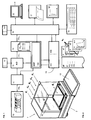
- FIG. 1 shows an exemplary representation of the block diagram of in FIG. 2 shown balance 1, a transmitter 10, for example, those described in [5] and in FIG. 3 shown load cell, which consists of a strain gauges provided with Kraftaufdorfauerauer 10 which is connected by means of screws 1021, 1012 with a Waagschalenarme 102 and a fastening part 101, which in turn is connected by screws 22 to the housing 2 of the balance 1.
- the strain gauges are connected via a ribbon cable 1011 with a circuit module 103, on the below described in more detail, including the signal correction serving modules 11, 12, 13, 14, 15A are provided.
- shown modular load cell has particular advantages described in [5].
- the method according to the invention can also be implemented with any other structural design of the balance.
- a corresponding to a load analog measurement signal ms A is output via a processing for analog signals serving first signal processing unit 11 to an analog / digital converter 12, which outputs the digitized measurement signal ms D to a serving for processing digital signals second signal processing unit 13 in which the digitized measurement signal ms D is corrected on the basis of drift parameters P1, P2,... in such a way that signal deviations caused by drift phenomena, in particular creep, are compensated.
- the second signal processing unit 13 is provided with a processor 130, preferably a signal processor and connected to a memory unit 15 or 15A.
- the signal processor 130 processes an optimization program P OPT which, like lists pl, is stored in the memory unit 15 with the drift parameters P1, P2,... And registered signal curves s1, s2,.
- the second signal processing unit 13 outputs the corrected digital measurement signal ms DK to a main or host processor 16 which is connected to the memory unit 15, 15B with an input unit 19, for example a keyboard, with a display 18, for example a liquid crystal display Printer 17 and a central computer 20 is connected.
- the work division between the processors 130 and 16 in the implementation of the method can be arbitrarily set. Basically, only one processor is absolutely necessary. Accordingly, the sharing or sharing of the memory areas 15A, 15B in the memory unit 15 takes place.
- the signal processor 130 may, for example, under the control of the host processor 16 perform only individual method steps and forward the results for further processing.
- FIG. 1 shown that signals describing the state of the scale 1 and / or external influences, the signal processor 130 of sensors 14 via the analog / digital converter 12 and the host processor 16 of sensors 140 are fed directly.
- Signal curves s1, ..., sn shown as continuous amplitude curves as a function of time or as amplitude / time value pairs, preferably associated with a time and / or date information in the memory unit 15; 15A, for example in a circular buffer provided there.
- the signal curves s1, ..., sn are not or only partially corrected for them about the measuring process and the measuring device provide unadulterated information.
- the stored signal curves s1,..., Sn are used for the subsequent optimization of the scale 1 and not for evaluation by the user, which normally takes place in parallel immediately after completion of a measuring or weighing process.
- sn can be subsequently rejected if at the registered time several other disturbances have been registered. For example, a message may be sent from a central computer 20 to the decentralized scales that an electrical fault has occurred on XX.XX.XXX from YY.YY to ZZ.ZZ which has affected various systems. In scale 1 falling, unreliable signal curves s2 can therefore be rejected during this period.
- FIG. 2 shows in an exemplary embodiment a suitable for carrying out the inventive method balance 1, in which the in FIG. 1 shown components 10, 11, ... are integrated in a housing 2.
- Symbolically represented is a non-complete series of actions d A , d E , d M , d W , d T and d L , which represent the state of Balance 1 and the measurement behavior of the balance 1 or determine the respective measurement history or at least influence.
- the actions of the user d A ie the settings of the balance 1 and the applications carried out are to be observed, which determine the current state of the balance 1 and its behavior.
- process parameters chosen by the user for the signal processing or the opening of a door, which serves to close the weighing chamber are important.
- the history of the previously performed applications or measurements is important, as described in [4].
- effects d E of the power supply and electrical interference fields mechanical effects such as vibrations, thermal effects d T , environmental effects d W , such as wind and humidity, as well as the behavior d L and properties of the measured load of great importance.
- Essential are interactions between the load and the environment. For example, a load may release moisture to or from the ambient air. Furthermore, there is a continuous heat exchange between the load and the environment, which can cause disturbing Konvetationsströmungen. The release or uptake of humidity or the convection caused by heat exchange may result in false readings superimposed on creep drift. If the drift caused by creep is compensated correctly by the balance, a drift caused by the load change remains, which should not be interpreted as creep for the optimization steps described below. If a change in the display by one or more units has not taken place by creeping but by a load change or other influences, this must be determined and the corresponding signal course sx rejected.
- the evaluation of the signal curves s1,..., Sn is preferably carried out by determining and evaluating State characteristics of the balance, which is dependent on the actions of the user or of the effects of the environment, and / or by detection and evaluation of waveform characteristics, which are extracted from the signal curves s1, ..., sn.
- the state of the balance preferably comprises all elements which have an influence on a measurement application, from which a signal curve s is obtained.
- the state of the scale is determined not only by the user's operating settings but also by the load applied and the environment.
- a non-creep drift in a measurement process can now be determined with few exceptions from the state features and / or from the waveform characteristics.
- the humidity and the temperature of the ambient air are measured. Further, the user may be prompted to measure a liquid. On the basis of these state characteristics, an expected load change due to the evaporation of liquid can be calculated or a corresponding risk taken into account.
- Creep drift curves are normally symmetrical, while drift caused by a load change is completely eliminated after unloading or removing the load from the scale.
- the determination of signal characteristics from the signal curves s is therefore, although usually more difficult, particularly valuable with regard to the assessment of their usability.
- drift parameters P1, P2,... are defined, by means of which drift deviations are corrected.
- the unique choice of static drift parameters P1, P2, ... and the correction of drift deviations are known from [4]. According to the invention, these drift parameters P1, P2,... are repeatedly checked by the user after the scale 1 has been installed and adapted to the changed properties of the balance 1 and optionally rechecked before use and / or submitted to the user for approval.
- FIG. 4 Changes in the creep-based drift behavior of scale 1 can be seen.
- uncorrected drift profiles s X , s Y , s Z are shown, which occur after applying a load. Displayed changes of the display in digits or display units are displayed within 15 minutes. It can be seen that the creep-based drift behavior of the balance 1 changes over time.
- the initialization of the method according to the invention takes place, for example, automatically at fixed time intervals, automatically after detection of disturbing drift deviations or manually by the user.
- the method for optimizing the drift parameters P1, P2 ,. .. is performed (see FIG. 7 ).
- At least some of the previously registered signal profiles s1, s3,... are taken from the memory unit 15 and fed sequentially to the signal processing unit 13, in which the correction of drift phenomena is based on new values for the drift parameters P1, P2,..., after which the corrected signal curves s1, s3,... are evaluated and optimized values for the drift parameters P1, P2,... are stored.
- the in FIG. 4 shown taken after six months, uncorrected waveform from the memory unit 15 and fed to the signal processing unit 13, in which the correction method based on the current drift parameters P1, P2, ... is performed.
- the signal progression is derived from that in FIG. 5 The course shown varies until an optimal course is found.
- the signal curves s1,..., Sn are progressively checked on the basis of current values for the drift parameters, after which, for each test step, if necessary after averaging the measurement results, a test value is calculated which corresponds to the quality of the correction achieved.
- the test values determined for each test step are then compared with one another, after which the values for the drift parameters P1, P2,... Of the best test value are stored as new, current values.
- FIG. 6 shows the waveforms of FIG. 4 corresponding signal curves s X , s Y , s Z which are practically completely corrected by means of individually adapted drift parameters P1, P2,...
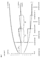
- the inventive method is based on FIG. 7 explained in a different way from another point of view. Shown is a curve L U which shows the creep-based uncompensated drift behavior or corresponding drift values that occur five minutes after application of a load over several months.
- the curve L U was recorded by sequential measurements and interpolation of the measured values.
- the curve L CR shows the stepwise course of the compensation values adjusted in two-month increments, which were determined on the basis of the adaptively adjusted values of the drift parameters P1, P2,...
- the sawtooth-shaped curve L C shows the drift behavior of the balance 1, which is justified by creep and is selectively corrected within the intervals CI1, CI2,... By the compensation values L CR .
- TH LD a threshold value corresponding to a maximum tolerable drift deviation and after exceeding which, the method according to the invention is carried out.
- TH LD a threshold value corresponding to a maximum tolerable drift deviation and after exceeding which, the method according to the invention is carried out.
- the method according to the invention is carried out in each case as early as necessary and as late as possible.
- FIG. 8 shows the scale 1 of FIG. 2 in a suitable for automatic or semi-automatic implementation of the inventive method embodiment.
- a load 5 was placed by the user and left for a longer time.
- the display 18 of the scale 1 for example a liquid crystal screen, the signal profile s-n registered during the time t is shown, which indicates a drift.
- This process can be carried out by a balance with at least one automatically adjustable adjustment weight without the assistance of the user.
- the user can now enter on the keyboard 19 that the condition of the scale is suitable for carrying out the optimization method. Furthermore, he can start the optimization process by pressing another key and take over the optimized values for the drift parameters P1, P2,... Later with another keypress.
- the optimization program can automatically detect a drift and automatically start the optimization process, after which optimized values for the drift parameters P1, P2,... Automatically or only after confirmation by the user instead of the previous ones Parameter values are stored.
- the values for the drift parameters P1, P2,... can therefore be optimized on the basis of a currently recorded signal curve sn.
- the scale 1 can also be used to automatically optimize the values be provided for the drift parameters P1, P2, ... by means of signal curves s1, ..., sn, which were registered earlier.
- the user preferably again has the option of confirming the suitable state for each signal curve s to be stored and subsequently used (see key or input field ⁇ CONDITION OK>), to start the optimization method (see key or input field ⁇ OPTIMIZE>) and the optimized ones Take over values for the drift parameters P1, P2, ... instead of the previous values (see button OR input field ⁇ ACCEPT>).
- the inventive method and the force measuring device 1 according to the invention have been described and illustrated in preferred embodiments.
- the force measuring device has been described in the embodiment of a balance 1.
- the invention is also in other force measuring devices, such as gravimetric gauges, weigh modules, load cells and force sensors, which may optionally form part of a scale used.
- the method is versatile and not limited to the explicitly stated factors that can cause drifting phenomena.
- the method is of course not limited to a specific choice, configuration, grouping and application of the drift parameters P1, P2,....
- various centrally or decentrally arranged storage media such as, for example, magnetically or optically writable and readable storage devices as well as static or dynamic semiconductor memories, can be used.
Landscapes
- Physics & Mathematics (AREA)
- General Physics & Mathematics (AREA)
- Indication And Recording Devices For Special Purposes And Tariff Metering Devices (AREA)
Priority Applications (5)
| Application Number | Priority Date | Filing Date | Title |
|---|---|---|---|
| EP05105422A EP1736745B1 (de) | 2005-06-21 | 2005-06-21 | Verfahren zur adaptiven Korrektur von Drifterscheinungen bei einer Kraftmessvorrichtung sowie eine Kraftmessvorrichtung zur Durchführung des Verfahrens. |
| PL05105422T PL1736745T3 (pl) | 2005-06-21 | 2005-06-21 | Sposób adaptacyjnej korekcji zjawisk dryftu w urządzeniu do pomiaru siły oraz urządzenie do pomiaru siły dla realizacji sposobu |
| JP2006169844A JP5036228B2 (ja) | 2005-06-21 | 2006-06-20 | 力測定デバイス内のドリフト現象を適応的に補正する方法、および力測定デバイス |
| CN2006100940332A CN1884985B (zh) | 2005-06-21 | 2006-06-21 | 适应性修正测力装置的漂移现象的方法以及测力装置 |
| US11/471,637 US7516035B2 (en) | 2005-06-21 | 2006-06-21 | Method for the adaptive correction of drift phenomena in a force-measuring device, and force-measuring device |
Applications Claiming Priority (1)
| Application Number | Priority Date | Filing Date | Title |
|---|---|---|---|
| EP05105422A EP1736745B1 (de) | 2005-06-21 | 2005-06-21 | Verfahren zur adaptiven Korrektur von Drifterscheinungen bei einer Kraftmessvorrichtung sowie eine Kraftmessvorrichtung zur Durchführung des Verfahrens. |
Publications (2)
| Publication Number | Publication Date |
|---|---|
| EP1736745A1 EP1736745A1 (de) | 2006-12-27 |
| EP1736745B1 true EP1736745B1 (de) | 2012-08-01 |
Family
ID=35134845
Family Applications (1)
| Application Number | Title | Priority Date | Filing Date |
|---|---|---|---|
| EP05105422A Expired - Lifetime EP1736745B1 (de) | 2005-06-21 | 2005-06-21 | Verfahren zur adaptiven Korrektur von Drifterscheinungen bei einer Kraftmessvorrichtung sowie eine Kraftmessvorrichtung zur Durchführung des Verfahrens. |
Country Status (5)
| Country | Link |
|---|---|
| US (1) | US7516035B2 (pl) |
| EP (1) | EP1736745B1 (pl) |
| JP (1) | JP5036228B2 (pl) |
| CN (1) | CN1884985B (pl) |
| PL (1) | PL1736745T3 (pl) |
Cited By (1)
| Publication number | Priority date | Publication date | Assignee | Title |
|---|---|---|---|---|
| CN113348416A (zh) * | 2019-01-18 | 2021-09-03 | 卡罗利·西普卡 | 测量系统和与测量系统相关的方法 |
Families Citing this family (27)
| Publication number | Priority date | Publication date | Assignee | Title |
|---|---|---|---|---|
| PL1736746T3 (pl) * | 2005-06-21 | 2012-12-31 | Mettler Toledo Gmbh | Sposób optymalizacji zachowania się urządzenia do pomiaru siły oraz urządzenie do pomiaru siły do realizacji tego sposobu |
| DE102007014711A1 (de) * | 2007-03-23 | 2008-09-25 | Mettler-Toledo Ag | Verfahren zur Überwachung und/oder Bestimmung des Zustandes einer Kraftmessvorrichtung und Kraftmessvorrichtung |
| JP5139009B2 (ja) * | 2007-09-06 | 2013-02-06 | 大和製衡株式会社 | 荷重検出器のクリープ特性同定装置およびこれを用いたクリープ誤差補償装置、ならびにクリープ回復特性同定装置およびこれを用いたクリープ回復誤差補償装置 |
| CN101629845B (zh) * | 2008-07-17 | 2011-07-20 | 梅特勒-托利多仪器(上海)有限公司 | 电子天平上电初期量程误差的补偿方法 |
| DE102008058804A1 (de) * | 2008-11-24 | 2010-06-02 | Mettler-Toledo Ag | Verfahren zur Überwachung einer potentiometrischen Messsonde |
| WO2012071560A1 (en) | 2010-11-24 | 2012-05-31 | Hysitron, Inc. | Mechanical testing instruments including onboard data |
| JP5666930B2 (ja) * | 2011-01-28 | 2015-02-12 | 株式会社エー・アンド・デイ | 計量装置 |
| US20140060939A1 (en) * | 2011-05-13 | 2014-03-06 | David Aaron Eppert | Load-measuring, fleet asset tracking and data management system for load-lifting vehicles |
| US8841564B1 (en) * | 2013-04-29 | 2014-09-23 | R+L Carriers, Inc. | Weigh scaled vehicle calibration systems and methods |
| DE102013009452A1 (de) * | 2013-06-06 | 2014-12-11 | Saurer Germany Gmbh & Co. Kg | Nullpunktabgleich eines Fadenzugkraftsensors |
| US20160356632A1 (en) * | 2015-06-02 | 2016-12-08 | Empire Technology Development Llc | Sensor degradation compensation |
| EP3538738B1 (en) * | 2016-11-09 | 2023-06-07 | Salunda Limited | Sensor for a rotatable element |
| CN107389175A (zh) * | 2017-07-13 | 2017-11-24 | 铜陵凯特尔科技有限责任公司 | 一种基于精度调节的智能称重系统 |
| CN107687889A (zh) * | 2017-07-13 | 2018-02-13 | 铜陵凯特尔科技有限责任公司 | 一种基于多次校准的智能称重系统 |
| CN109145398B (zh) * | 2018-07-30 | 2024-01-05 | 白杨 | 一种基于称重的货品数量计算方法 |
| US10801882B2 (en) * | 2018-11-16 | 2020-10-13 | General Electric Company | Methods and system for obtaining a force measurement with reduced drift effects |
| CN109631975A (zh) * | 2018-12-30 | 2019-04-16 | 郑州衡量科技股份有限公司 | 一种抑制传感器零飘的自动零点跟踪算法 |
| CN111044405B (zh) * | 2020-01-02 | 2022-06-28 | 西安建筑科技大学 | 一种针对热重曲线漂移误差的修正方法 |
| CN111412968B (zh) * | 2020-05-14 | 2024-08-23 | 哈尔滨理工大学 | 称重应变传感器信号量值传递电路、关键单元及传递方法 |
| WO2022137500A1 (ja) * | 2020-12-25 | 2022-06-30 | 株式会社 エー・アンド・デイ | 電子天びん、および電子天びんの秤量精度の安定化方法 |
| DE102021118296B4 (de) * | 2021-07-15 | 2025-07-31 | Vega Grieshaber Kg | Verfahren zur Driftkompensation eines Drucksensors und Drucksensor |
| CN115389996A (zh) * | 2022-08-25 | 2022-11-25 | 广东迅森磁电有限公司 | 磁通计的结果修正方法、装置、磁通计以及存储介质 |
| CN116295741B (zh) * | 2023-02-23 | 2023-08-22 | 浙江大学 | 一种基于气垫的体重监测方法及系统 |
| CN117249873B (zh) * | 2023-11-20 | 2024-01-30 | 精智未来(广州)智能科技有限公司 | 一种用于气体分子分析的质量监测方法及设备 |
| CN117928884B (zh) * | 2024-03-22 | 2024-05-28 | 中国空气动力研究与发展中心高速空气动力研究所 | 考虑天平时间相关数据修正的高速连续式风洞运行方法 |
| CN120489316B (zh) * | 2025-07-16 | 2025-09-16 | 山东金钟科技集团股份有限公司 | 传感器误差校准方法、装置、设备及存储介质 |
| CN120970790A (zh) * | 2025-10-21 | 2025-11-18 | 南通大衡称重设备有限公司 | 一种用于电子秤的漂移数据处理方法、系统及存储介质 |
Citations (4)
| Publication number | Priority date | Publication date | Assignee | Title |
|---|---|---|---|---|
| US4656599A (en) * | 1983-11-09 | 1987-04-07 | Sartorius Gmbh | Electric balance |
| US4836308A (en) * | 1988-04-04 | 1989-06-06 | General Electrodynamics Corporation | Highly accurate platform weighing system |
| DE19709624C1 (de) * | 1997-03-08 | 1998-07-02 | Sartorius Gmbh | Verfahren zur Temperaturkompensation einer elektronischen Waage |
| DE10353414B3 (de) * | 2003-11-15 | 2005-01-27 | Sartorius Ag | Elektronische Waage |
Family Cites Families (9)
| Publication number | Priority date | Publication date | Assignee | Title |
|---|---|---|---|---|
| US4691290A (en) * | 1984-08-06 | 1987-09-01 | Reliance Electric Company | Creep-compensated weighing apparatus |
| CH670508A5 (pl) * | 1986-05-23 | 1989-06-15 | Mettler Instrumente Ag | |
| GB2221039A (en) * | 1988-07-05 | 1990-01-24 | Peter Adam Reuter | Load cell device with integral data processing/output means |
| AU634367B2 (en) * | 1990-05-16 | 1993-02-18 | Mettler-Toledo, Inc. | Hysteresis-compensated weighing apparatus and method |
| US5623128A (en) * | 1994-03-01 | 1997-04-22 | Mettler-Toledo, Inc. | Load cell with modular calibration components |
| US5606516A (en) * | 1995-08-07 | 1997-02-25 | Fairbanks Scales Inc. | Digitally compensated hydraulic scale system |
| JPH112573A (ja) * | 1997-06-13 | 1999-01-06 | Yamato Scale Co Ltd | 力検知器の経時誤差を補償する方法及び装置 |
| DE19813459A1 (de) * | 1998-03-26 | 1999-09-30 | Mettler Toledo Gmbh | Elastisch verformbares Bauteil und Verfahren zu seiner Herstellung |
| EP1347274B1 (de) | 2002-03-18 | 2005-08-03 | Mettler-Toledo GmbH | Modulare Kraftmesszelle für eine Waage und Waage |
-
2005
- 2005-06-21 PL PL05105422T patent/PL1736745T3/pl unknown
- 2005-06-21 EP EP05105422A patent/EP1736745B1/de not_active Expired - Lifetime
-
2006
- 2006-06-20 JP JP2006169844A patent/JP5036228B2/ja active Active
- 2006-06-21 US US11/471,637 patent/US7516035B2/en active Active
- 2006-06-21 CN CN2006100940332A patent/CN1884985B/zh active Active
Patent Citations (4)
| Publication number | Priority date | Publication date | Assignee | Title |
|---|---|---|---|---|
| US4656599A (en) * | 1983-11-09 | 1987-04-07 | Sartorius Gmbh | Electric balance |
| US4836308A (en) * | 1988-04-04 | 1989-06-06 | General Electrodynamics Corporation | Highly accurate platform weighing system |
| DE19709624C1 (de) * | 1997-03-08 | 1998-07-02 | Sartorius Gmbh | Verfahren zur Temperaturkompensation einer elektronischen Waage |
| DE10353414B3 (de) * | 2003-11-15 | 2005-01-27 | Sartorius Ag | Elektronische Waage |
Cited By (1)
| Publication number | Priority date | Publication date | Assignee | Title |
|---|---|---|---|---|
| CN113348416A (zh) * | 2019-01-18 | 2021-09-03 | 卡罗利·西普卡 | 测量系统和与测量系统相关的方法 |
Also Published As
| Publication number | Publication date |
|---|---|
| JP2007003522A (ja) | 2007-01-11 |
| PL1736745T3 (pl) | 2012-12-31 |
| CN1884985A (zh) | 2006-12-27 |
| EP1736745A1 (de) | 2006-12-27 |
| US20070010960A1 (en) | 2007-01-11 |
| JP5036228B2 (ja) | 2012-09-26 |
| CN1884985B (zh) | 2010-12-01 |
| US7516035B2 (en) | 2009-04-07 |
Similar Documents
| Publication | Publication Date | Title |
|---|---|---|
| EP1736745B1 (de) | Verfahren zur adaptiven Korrektur von Drifterscheinungen bei einer Kraftmessvorrichtung sowie eine Kraftmessvorrichtung zur Durchführung des Verfahrens. | |
| EP1736746B1 (de) | Verfahren zur Optimierung des Verhaltens einer Kraftmessvorrichtung sowie eine Kraftmessvorrichtung zur Durchführung des Verfahrens. | |
| DE3889253T3 (de) | Digitale Einrichtung zum Kompensieren der Lastverschiebung. | |
| DE69419183T2 (de) | Methode zur temperaturkompensation für druckwandler | |
| CH701958B1 (de) | Verfahren zum Betreiben einer Messstelle und Messstelle. | |
| DE2904261C2 (de) | Elektronische Waage, insb. Ladenwaage | |
| EP1963825A1 (de) | Kalibrierung im laborreferenzverfahren | |
| DE3709707C2 (de) | Verfahren zum automatischen Abgleich einer hochauflösenden elektronischen Waage | |
| DE102019217333A1 (de) | Verfahren zum Bestimmen mindestens eines Temperaturkompensationsparameters zur Kompensation von Temperatureinflüssen auf die Messwerte eines Sensorsystems | |
| DE102019214984A1 (de) | Inertialsensor und computerimplementiertes Verfahren zur Selbstkalibrierung eines Inertialsensors | |
| EP0354218A1 (de) | verfahren für die eichung und den betrieb einer waage | |
| DE3719532A1 (de) | Kraftmesseinrichtung | |
| DE3873927T2 (de) | Elektronische steueranordnung. | |
| DE102006040409A1 (de) | Verfahren zum Bestimmen einer Kennlinie einer Fühleranordnung | |
| DE102010016968A1 (de) | Verfahren zum Betrieb eines Messgerätes mit einem mindestens drei Füße aufweisenden Chassis | |
| EP0682235A1 (de) | Verfahren und Vorrichtung zum Abgleich eines Messkörpers eines Messwertaufnehmers | |
| DE102021205378A1 (de) | Sensorstruktur und Drucksensor | |
| WO2020132708A1 (de) | Verfahren zur überwachung der lebensdauer eines verbauten wälzlagers | |
| DE102023123698A1 (de) | Verfahren zum Bestimmen einer Oberflächentemperatur eines Bauteils und Messvorrichtung zum Ausführen des Verfahrens | |
| DE102008064163A1 (de) | Wägezelle | |
| DE102019122383A1 (de) | Digitale Messwertkorrektur bei einer in einer Anschlussstruktur eingebauten Kraftmessvorrichtung | |
| DE102021113265A1 (de) | Drucksensor mit Kompensationseinheit und Verfahren zur Kompensation | |
| WO2011009942A1 (de) | Verfahren zur ermittlung von prozessgrössen für eine kraftmessvorrichtung und kraftmessvorrichtung | |
| EP1826540A2 (de) | Verfahren zum Austauschen von Wägezellen | |
| DE102013020395A1 (de) | Verfahren zur Kompensation der Temperaturabhängigkeit eines Nutzsignals |
Legal Events
| Date | Code | Title | Description |
|---|---|---|---|
| PUAI | Public reference made under article 153(3) epc to a published international application that has entered the european phase |
Free format text: ORIGINAL CODE: 0009012 |
|
| AK | Designated contracting states |
Kind code of ref document: A1 Designated state(s): AT BE BG CH CY CZ DE DK EE ES FI FR GB GR HU IE IS IT LI LT LU MC NL PL PT RO SE SI SK TR |
|
| AX | Request for extension of the european patent |
Extension state: AL BA HR LV MK YU |
|
| 17P | Request for examination filed |
Effective date: 20070613 |
|
| AKX | Designation fees paid |
Designated state(s): AT BE BG CH CY CZ DE DK EE ES FI FR GB GR HU IE IS IT LI LT LU MC NL PL PT RO SE SI SK TR |
|
| 17Q | First examination report despatched |
Effective date: 20070823 |
|
| GRAP | Despatch of communication of intention to grant a patent |
Free format text: ORIGINAL CODE: EPIDOSNIGR1 |
|
| GRAS | Grant fee paid |
Free format text: ORIGINAL CODE: EPIDOSNIGR3 |
|
| GRAA | (expected) grant |
Free format text: ORIGINAL CODE: 0009210 |
|
| AK | Designated contracting states |
Kind code of ref document: B1 Designated state(s): AT BE BG CH CY CZ DE DK EE ES FI FR GB GR HU IE IS IT LI LT LU MC NL PL PT RO SE SI SK TR |
|
| REG | Reference to a national code |
Ref country code: GB Ref legal event code: FG4D Free format text: NOT ENGLISH |
|
| REG | Reference to a national code |
Ref country code: DE Ref legal event code: R081 Ref document number: 502005012954 Country of ref document: DE Owner name: METTLER-TOLEDO GMBH, CH Free format text: FORMER OWNER: METTLER-TOLEDO AG, GREIFENSEE, CH |
|
| REG | Reference to a national code |
Ref country code: AT Ref legal event code: REF Ref document number: 568917 Country of ref document: AT Kind code of ref document: T Effective date: 20120815 Ref country code: CH Ref legal event code: EP |
|
| REG | Reference to a national code |
Ref country code: IE Ref legal event code: FG4D Free format text: LANGUAGE OF EP DOCUMENT: GERMAN |
|
| REG | Reference to a national code |
Ref country code: DE Ref legal event code: R096 Ref document number: 502005012954 Country of ref document: DE Effective date: 20120927 |
|
| REG | Reference to a national code |
Ref country code: NL Ref legal event code: VDEP Effective date: 20120801 |
|
| REG | Reference to a national code |
Ref country code: PL Ref legal event code: T3 |
|
| REG | Reference to a national code |
Ref country code: LT Ref legal event code: MG4D Effective date: 20120829 |
|
| PG25 | Lapsed in a contracting state [announced via postgrant information from national office to epo] |
Ref country code: IS Free format text: LAPSE BECAUSE OF FAILURE TO SUBMIT A TRANSLATION OF THE DESCRIPTION OR TO PAY THE FEE WITHIN THE PRESCRIBED TIME-LIMIT Effective date: 20121201 Ref country code: LT Free format text: LAPSE BECAUSE OF FAILURE TO SUBMIT A TRANSLATION OF THE DESCRIPTION OR TO PAY THE FEE WITHIN THE PRESCRIBED TIME-LIMIT Effective date: 20120801 Ref country code: CY Free format text: LAPSE BECAUSE OF FAILURE TO SUBMIT A TRANSLATION OF THE DESCRIPTION OR TO PAY THE FEE WITHIN THE PRESCRIBED TIME-LIMIT Effective date: 20120801 Ref country code: FI Free format text: LAPSE BECAUSE OF FAILURE TO SUBMIT A TRANSLATION OF THE DESCRIPTION OR TO PAY THE FEE WITHIN THE PRESCRIBED TIME-LIMIT Effective date: 20120801 |
|
| PG25 | Lapsed in a contracting state [announced via postgrant information from national office to epo] |
Ref country code: SI Free format text: LAPSE BECAUSE OF FAILURE TO SUBMIT A TRANSLATION OF THE DESCRIPTION OR TO PAY THE FEE WITHIN THE PRESCRIBED TIME-LIMIT Effective date: 20120801 Ref country code: GR Free format text: LAPSE BECAUSE OF FAILURE TO SUBMIT A TRANSLATION OF THE DESCRIPTION OR TO PAY THE FEE WITHIN THE PRESCRIBED TIME-LIMIT Effective date: 20121102 Ref country code: PT Free format text: LAPSE BECAUSE OF FAILURE TO SUBMIT A TRANSLATION OF THE DESCRIPTION OR TO PAY THE FEE WITHIN THE PRESCRIBED TIME-LIMIT Effective date: 20121203 Ref country code: SE Free format text: LAPSE BECAUSE OF FAILURE TO SUBMIT A TRANSLATION OF THE DESCRIPTION OR TO PAY THE FEE WITHIN THE PRESCRIBED TIME-LIMIT Effective date: 20120801 |
|
| PG25 | Lapsed in a contracting state [announced via postgrant information from national office to epo] |
Ref country code: NL Free format text: LAPSE BECAUSE OF FAILURE TO SUBMIT A TRANSLATION OF THE DESCRIPTION OR TO PAY THE FEE WITHIN THE PRESCRIBED TIME-LIMIT Effective date: 20120801 |
|
| PG25 | Lapsed in a contracting state [announced via postgrant information from national office to epo] |
Ref country code: CZ Free format text: LAPSE BECAUSE OF FAILURE TO SUBMIT A TRANSLATION OF THE DESCRIPTION OR TO PAY THE FEE WITHIN THE PRESCRIBED TIME-LIMIT Effective date: 20120801 Ref country code: ES Free format text: LAPSE BECAUSE OF FAILURE TO SUBMIT A TRANSLATION OF THE DESCRIPTION OR TO PAY THE FEE WITHIN THE PRESCRIBED TIME-LIMIT Effective date: 20121112 Ref country code: EE Free format text: LAPSE BECAUSE OF FAILURE TO SUBMIT A TRANSLATION OF THE DESCRIPTION OR TO PAY THE FEE WITHIN THE PRESCRIBED TIME-LIMIT Effective date: 20120801 Ref country code: DK Free format text: LAPSE BECAUSE OF FAILURE TO SUBMIT A TRANSLATION OF THE DESCRIPTION OR TO PAY THE FEE WITHIN THE PRESCRIBED TIME-LIMIT Effective date: 20120801 Ref country code: RO Free format text: LAPSE BECAUSE OF FAILURE TO SUBMIT A TRANSLATION OF THE DESCRIPTION OR TO PAY THE FEE WITHIN THE PRESCRIBED TIME-LIMIT Effective date: 20120801 |
|
| PG25 | Lapsed in a contracting state [announced via postgrant information from national office to epo] |
Ref country code: SK Free format text: LAPSE BECAUSE OF FAILURE TO SUBMIT A TRANSLATION OF THE DESCRIPTION OR TO PAY THE FEE WITHIN THE PRESCRIBED TIME-LIMIT Effective date: 20120801 Ref country code: IT Free format text: LAPSE BECAUSE OF FAILURE TO SUBMIT A TRANSLATION OF THE DESCRIPTION OR TO PAY THE FEE WITHIN THE PRESCRIBED TIME-LIMIT Effective date: 20120801 |
|
| PLBE | No opposition filed within time limit |
Free format text: ORIGINAL CODE: 0009261 |
|
| STAA | Information on the status of an ep patent application or granted ep patent |
Free format text: STATUS: NO OPPOSITION FILED WITHIN TIME LIMIT |
|
| 26N | No opposition filed |
Effective date: 20130503 |
|
| PG25 | Lapsed in a contracting state [announced via postgrant information from national office to epo] |
Ref country code: BG Free format text: LAPSE BECAUSE OF FAILURE TO SUBMIT A TRANSLATION OF THE DESCRIPTION OR TO PAY THE FEE WITHIN THE PRESCRIBED TIME-LIMIT Effective date: 20121101 |
|
| REG | Reference to a national code |
Ref country code: DE Ref legal event code: R097 Ref document number: 502005012954 Country of ref document: DE Effective date: 20130503 |
|
| REG | Reference to a national code |
Ref country code: CH Ref legal event code: PCOW Free format text: NEW ADDRESS: IM LANGACHER 44, 8606 GREIFENSEE (CH) |
|
| BERE | Be: lapsed |
Owner name: METTLER-TOLEDO A.G. Effective date: 20130630 |
|
| PG25 | Lapsed in a contracting state [announced via postgrant information from national office to epo] |
Ref country code: MC Free format text: LAPSE BECAUSE OF FAILURE TO SUBMIT A TRANSLATION OF THE DESCRIPTION OR TO PAY THE FEE WITHIN THE PRESCRIBED TIME-LIMIT Effective date: 20120801 |
|
| REG | Reference to a national code |
Ref country code: IE Ref legal event code: MM4A |
|
| PG25 | Lapsed in a contracting state [announced via postgrant information from national office to epo] |
Ref country code: BE Free format text: LAPSE BECAUSE OF NON-PAYMENT OF DUE FEES Effective date: 20130630 |
|
| PG25 | Lapsed in a contracting state [announced via postgrant information from national office to epo] |
Ref country code: IE Free format text: LAPSE BECAUSE OF NON-PAYMENT OF DUE FEES Effective date: 20130621 |
|
| REG | Reference to a national code |
Ref country code: AT Ref legal event code: MM01 Ref document number: 568917 Country of ref document: AT Kind code of ref document: T Effective date: 20130621 |
|
| PG25 | Lapsed in a contracting state [announced via postgrant information from national office to epo] |
Ref country code: AT Free format text: LAPSE BECAUSE OF NON-PAYMENT OF DUE FEES Effective date: 20130621 |
|
| PG25 | Lapsed in a contracting state [announced via postgrant information from national office to epo] |
Ref country code: TR Free format text: LAPSE BECAUSE OF FAILURE TO SUBMIT A TRANSLATION OF THE DESCRIPTION OR TO PAY THE FEE WITHIN THE PRESCRIBED TIME-LIMIT Effective date: 20120801 |
|
| PG25 | Lapsed in a contracting state [announced via postgrant information from national office to epo] |
Ref country code: HU Free format text: LAPSE BECAUSE OF FAILURE TO SUBMIT A TRANSLATION OF THE DESCRIPTION OR TO PAY THE FEE WITHIN THE PRESCRIBED TIME-LIMIT; INVALID AB INITIO Effective date: 20050621 Ref country code: LU Free format text: LAPSE BECAUSE OF NON-PAYMENT OF DUE FEES Effective date: 20130621 |
|
| REG | Reference to a national code |
Ref country code: CH Ref legal event code: PFA Owner name: METTLER-TOLEDO GMBH, CH Free format text: FORMER OWNER: METTLER-TOLEDO AG, CH |
|
| REG | Reference to a national code |
Ref country code: FR Ref legal event code: PLFP Year of fee payment: 12 |
|
| REG | Reference to a national code |
Ref country code: FR Ref legal event code: PLFP Year of fee payment: 13 |
|
| REG | Reference to a national code |
Ref country code: DE Ref legal event code: R081 Ref document number: 502005012954 Country of ref document: DE Owner name: METTLER-TOLEDO GMBH, CH Free format text: FORMER OWNER: METTLER-TOLEDO AG, GREIFENSEE, CH |
|
| PGFP | Annual fee paid to national office [announced via postgrant information from national office to epo] |
Ref country code: GB Payment date: 20170526 Year of fee payment: 13 Ref country code: FR Payment date: 20170518 Year of fee payment: 13 |
|
| REG | Reference to a national code |
Ref country code: FR Ref legal event code: CJ Effective date: 20180409 |
|
| GBPC | Gb: european patent ceased through non-payment of renewal fee |
Effective date: 20180621 |
|
| PG25 | Lapsed in a contracting state [announced via postgrant information from national office to epo] |
Ref country code: GB Free format text: LAPSE BECAUSE OF NON-PAYMENT OF DUE FEES Effective date: 20180621 Ref country code: FR Free format text: LAPSE BECAUSE OF NON-PAYMENT OF DUE FEES Effective date: 20180630 |
|
| PGFP | Annual fee paid to national office [announced via postgrant information from national office to epo] |
Ref country code: DE Payment date: 20240627 Year of fee payment: 20 |
|
| PGFP | Annual fee paid to national office [announced via postgrant information from national office to epo] |
Ref country code: PL Payment date: 20240527 Year of fee payment: 20 |
|
| PGFP | Annual fee paid to national office [announced via postgrant information from national office to epo] |
Ref country code: CH Payment date: 20240701 Year of fee payment: 20 |
|
| REG | Reference to a national code |
Ref country code: DE Ref legal event code: R071 Ref document number: 502005012954 Country of ref document: DE |
|
| REG | Reference to a national code |
Ref country code: CH Ref legal event code: PL |
|
| REG | Reference to a national code |
Ref country code: CH Ref legal event code: PL |