EP1736655A1 - Misfire detection system for internal combustion engine - Google Patents
Misfire detection system for internal combustion engine Download PDFInfo
- Publication number
- EP1736655A1 EP1736655A1 EP06013019A EP06013019A EP1736655A1 EP 1736655 A1 EP1736655 A1 EP 1736655A1 EP 06013019 A EP06013019 A EP 06013019A EP 06013019 A EP06013019 A EP 06013019A EP 1736655 A1 EP1736655 A1 EP 1736655A1
- Authority
- EP
- European Patent Office
- Prior art keywords
- rotation
- combustion
- time required
- misfire
- variation
- Prior art date
- Legal status (The legal status is an assumption and is not a legal conclusion. Google has not performed a legal analysis and makes no representation as to the accuracy of the status listed.)
- Granted
Links
Images



Classifications
-
- F—MECHANICAL ENGINEERING; LIGHTING; HEATING; WEAPONS; BLASTING
- F02—COMBUSTION ENGINES; HOT-GAS OR COMBUSTION-PRODUCT ENGINE PLANTS
- F02D—CONTROLLING COMBUSTION ENGINES
- F02D41/00—Electrical control of supply of combustible mixture or its constituents
- F02D41/02—Circuit arrangements for generating control signals
- F02D41/04—Introducing corrections for particular operating conditions
- F02D41/12—Introducing corrections for particular operating conditions for deceleration
- F02D41/123—Introducing corrections for particular operating conditions for deceleration the fuel injection being cut-off
-
- F—MECHANICAL ENGINEERING; LIGHTING; HEATING; WEAPONS; BLASTING
- F02—COMBUSTION ENGINES; HOT-GAS OR COMBUSTION-PRODUCT ENGINE PLANTS
- F02D—CONTROLLING COMBUSTION ENGINES
- F02D41/00—Electrical control of supply of combustible mixture or its constituents
- F02D41/02—Circuit arrangements for generating control signals
- F02D41/14—Introducing closed-loop corrections
- F02D41/1497—With detection of the mechanical response of the engine
- F02D41/1498—With detection of the mechanical response of the engine measuring engine roughness
-
- G—PHYSICS
- G01—MEASURING; TESTING
- G01M—TESTING STATIC OR DYNAMIC BALANCE OF MACHINES OR STRUCTURES; TESTING OF STRUCTURES OR APPARATUS, NOT OTHERWISE PROVIDED FOR
- G01M15/00—Testing of engines
- G01M15/04—Testing internal-combustion engines
- G01M15/11—Testing internal-combustion engines by detecting misfire
-
- F—MECHANICAL ENGINEERING; LIGHTING; HEATING; WEAPONS; BLASTING
- F02—COMBUSTION ENGINES; HOT-GAS OR COMBUSTION-PRODUCT ENGINE PLANTS
- F02D—CONTROLLING COMBUSTION ENGINES
- F02D41/00—Electrical control of supply of combustible mixture or its constituents
- F02D41/02—Circuit arrangements for generating control signals
- F02D41/14—Introducing closed-loop corrections
- F02D41/1401—Introducing closed-loop corrections characterised by the control or regulation method
- F02D2041/1413—Controller structures or design
- F02D2041/1432—Controller structures or design the system including a filter, e.g. a low pass or high pass filter
-
- F—MECHANICAL ENGINEERING; LIGHTING; HEATING; WEAPONS; BLASTING
- F02—COMBUSTION ENGINES; HOT-GAS OR COMBUSTION-PRODUCT ENGINE PLANTS
- F02D—CONTROLLING COMBUSTION ENGINES
- F02D2200/00—Input parameters for engine control
- F02D2200/02—Input parameters for engine control the parameters being related to the engine
- F02D2200/10—Parameters related to the engine output, e.g. engine torque or engine speed
- F02D2200/1015—Engines misfires
-
- F—MECHANICAL ENGINEERING; LIGHTING; HEATING; WEAPONS; BLASTING
- F02—COMBUSTION ENGINES; HOT-GAS OR COMBUSTION-PRODUCT ENGINE PLANTS
- F02D—CONTROLLING COMBUSTION ENGINES
- F02D41/00—Electrical control of supply of combustible mixture or its constituents
- F02D41/009—Electrical control of supply of combustible mixture or its constituents using means for generating position or synchronisation signals
Definitions
- the present invention relates to a system for accurately detecting the presence or absence of a misfire in an internal combustion engine. More particularly, the present invention relates to a misfire detection system for detecting a misfire repeated per 360° CA (crank angle) (i.e., an opposed cylinder misfire) with high accuracy.
- a misfire detection system for detecting a misfire repeated per 360° CA (crank angle) (i.e., an opposed cylinder misfire) with high accuracy.
- One known misfire detection system for a multi-cylinder internal combustion engine comprises an angular speed detecting unit for detecting an angular speed of rotation of a crankshaft during combustion of each cylinder, a first rotation change computing unit for computing a first rotation change by determining a deviation in angular speed between two cylinders in which an explosion stroke takes place successively, a second rotation change computing unit for computing a second rotation change by determining a deviation in angular speed between the two cylinders at timing before 360° CA from the timing when the angular speeds have been detected by the first rotation change computing unit to compute the first rotation change, an addition unit for adding the first rotation change computed by the first rotation change computing unit and the second rotation change computed by the second rotation change computing unit, and a misfire detecting unit for detecting a misfire generated per 360° CA by comparing the added rotation change obtained from the addition unit with a preset determination value (see Patent Document 1: Japanese Patent No. 3463476 ).
- An object of the present invention is to provide a misfire detection system capable of detecting a misfire in an internal combustion engine with high accuracy.
- the present invention provides a misfire detection system for an internal combustion engine, comprising a rotation detecting unit for measuring a time required for a crankshaft of an internal combustion engine to rotate through a certain angle, and/or a signal processing unit for processing the time required for the rotation and detecting a misfire in the internal combustion engine, wherein the signal processing unit comprises a non-combustion state time-required-for-rotation memory for storing the time required for the rotation per cylinder when a fuel cut command is issued; a combustion variation memory in which a combustion variation per cylinder is stored in a stage of engine production; a filter for extracting a particular component from a value obtained by subtracting the sum of the time required for the rotation in a non-combustion state and the combustion variation, which are outputted respectively from the two memories, corresponding to a cylinder determined to be in the combustion stroke, from the time required for the rotation outputted from the rotation detecting unit; and/or a threshold determination unit for determining the occurrence of a mis
- the present invention it is possible to compensate an error of the time required for the rotation, which is caused by a manufacturing error of a ring gear and combustion variations, and to detect a misfire, particularly an opposed cylinder misfire, with high accuracy. Since the misfire can be detected with high accuracy, unburned fuel can be prevented from being released to the atmosphere.
- Fig. 1 is a block diagram of a misfire detection system according to a first embodiment of the present invention. The first embodiment of the present invention will be described below with reference to Fig. 1.
- the misfire detection system mainly comprises a rotation detecting unit 1 for measuring a time required for a crankshaft of an internal combustion engine to rotate through a certain angle, and a signal processing unit 2 for processing the time required for the rotation and detecting a misfire in the internal combustion engine.
- the rotation detecting unit 1 comprises a ring gear 11 and a magnetic sensor 12.
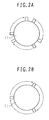
- the ring gear 11 is provided with teeth as shown in Figs. 2A and 2B.
- an output of the magnetic sensor 12 is changed.
- the time required for the ring gear 11 (crankshaft) to rotate the certain angle is detected.
- Figs. 2A and 2B show the ring gear 11 suitable for use in a 6-cylinder internal combustion engine. In the case of the 6-cylinder internal combustion engine, because three cylinders are subjected to explosion while the crankshaft makes one rotation, a tooth-to-tooth circumferential span indicated by an arrow-headed circular arc in each of Figs.
- the tooth-to-tooth circumferential span in Fig. 2A corresponds to an angle through which the ring gear 11 rotates during the explosion stroke of one cylinder when an engine revolution speed is low
- the tooth-to-tooth circumferential span in Fig. 2B corresponds to an angle through which the ring gear 11 rotates during the explosion stroke of one cylinder when the engine revolution speed is high.
- Fig. 3 shows one example of configuration of the signal processing unit in the misfire detection system.
- the signal processing unit 2 comprises a non-combustion state time-required-for-rotation memory 21 for storing the time required for the rotation per cylinder when a fuel cut command is issued, a combustion variation memory 22 in which a combustion variation per cylinder is stored in a stage of engine production, a filter 23 for extracting a particular component from a value obtained by subtracting the sum of the time required for the rotation in a non-combustion state and the combustion variation, which are outputted respectively from the above two memories, corresponding to a cylinder determined to be in a combustion stroke, from the time required for the rotation outputted from the rotation detecting unit 1, and a threshold determination unit 24 for determining the occurrence of a misfire when an output of the filter 23 exceeds a threshold.
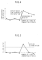
- Fig. 4 shows one example of the time required for the rotation, which is outputted from the rotation detecting unit 1 and is inputted to the signal processing unit 2.
- the time required for the rotation varies to some extent.
- the variation in the time required for the rotation is increased from that when no misfires are generated.
- the speed increase makes smaller the difference between the magnitude of the variation in the time required for the rotation when no misfires are generated and the magnitude of the variation in the time required for the rotation when a misfire is generated. Accordingly, the accuracy in misfire detection is reduced.
- Factors causing the variation in the time required for the rotation include the occurrence of a misfire, the combustion variation per cylinder, and a manufacturing error of the ring gear 11. Therefore, the accuracy in misfire detection can be increased by performing the misfire detection by using a value that is obtained by subtracting, from the time required for the rotation, variations attributable to the combustion variation per cylinder and the manufacturing error of the ring gear 11. The variation in the time required for the rotation attributable to the manufacturing error of the ring gear 11 appears as a variation in the time required for the rotation per cylinder when the fuel cut command is issued.
- the variation in the time required for the rotation attributable to the combustion variation mainly depends on unevenness in an amount of exhaust gas recirculation and an intake amount of air defined by design of an intake pipe.
- the latter variation primarily depends on design of an engine system, and hardly depends on individual differences of engines. Therefore, the variation in the time required for the rotation attributable to the combustion variation in some engine is substantially the same as that attributable to the combustion variation in another engine manufactured according to the same design.
- the signal processing unit 2 includes the non-combustion state time-required-for-rotation memory 21 and the combustion variation memory 22.
- the time required for the rotation per cylinder is stored in the non-combustion state time-required-for-rotation memory 21 with respect to a combustion stroke cylinder, i.e., a cylinder which is determined to be in the combustion stroke at that time by a combustion-stroke cylinder determining unit 5.
- the variation in the time required for the rotation attributable to the combustion variation is stored in the combustion variation memory 22 with respect to the combustion stroke cylinder.
- the time required for the rotation in the non-combustion state stored in the non-combustion state time-required-for-rotation memory 21 and corresponding to the combustion stroke cylinder and the variation in the time required for the rotation attributable to the combustion variation stored in the combustion variation memory 22 and corresponding to the combustion stroke cylinder are both subtracted from the time required for the rotation which is obtained from the rotation detecting unit 1.
- a value obtained by that subtraction represents the variation in the time required for the rotation attributable to the presence or absence of a misfire with high accuracy.
- that value is passed through the filter 23 to extract the variation in the time required for the rotation attributable to the presence or absence of a misfire, as shown in Fig. 5.
- One example of the filter 23 used for obtaining the variation in the time required for the rotation attributable to the presence or absence of a misfire, shown in Fig. 5, from the time required for the rotation, shown in Fig. 4, is a filter that subtracts, from the passage time of the cylinder in the combustion stroke at the present timing, the passage time of the preceding cylinder.
- the threshold determination unit 24 determines, as shown in Fig. 5, the presence of a misfire if an output of the filter 23 exceeds a certain value (threshold), and the absence of a misfire if it does not exceed the certain value.
- the time required for the rotation corresponding to the j-th cylinder when the fuel cut command is issued is ⁇ j and the difference ⁇ j and the time required for the rotation corresponding to the j-th cylinder when the fuel cut command is issued at the preceding timing is ⁇ j.
- the result of the misfire detection is plotted in the space defined by the axes Ti, Ti-1, Ti-2, etc., as shown in Fig. 6, such that a symbol x is marked when the result of the misfire detection shows the occurrence of a misfire and a symbol O is marked when the result of the misfire detection shows normal combustion (the space being referred to as a "misfire space").
- the misfire space is shifted by ⁇ j(i), ⁇ j(i-1), ⁇ j(i-2), etc. in directions of the axes Ti, Ti-1, Ti-2, etc. in comparison with the misfire space prior to the fuel cut when the non-combustion state time-required-for-rotation memory 21 is provided. Whether the present invention is implemented as in this first embodiment can be confirmed based on such a shift of the misfire space.
- the signal processing unit 2 in the first embodiment shown in Fig. 3 with no consideration paid to the engine revolution speed, the time required for the rotation in the non-combustion state and the combustion variation depend on the engine revolution speed.
- the signal processing unit 2 is constituted in consideration of the engine revolution speed.
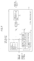
- Fig. 7 shows the configuration of the signal processing unit 2 in the second embodiment.
- the signal processing unit 2 in the second embodiment is constituted by adding an engine revolution speed computing unit 25 to the signal processing unit 2 in the first embodiment so that the time required for the rotation is compensated by using the data stored in the non-combustion state time-required-for-rotation memory 21 and the combustion variation memory 22 depending on the engine revolution speed.
- a time T_nofire required for the rotation in the non-combustion state is inversely proportional to the engine revolution speed n. Therefore, when fuel is cut, a value obtained by multiplying the passage time of each cylinder by the engine revolution speed is stored in the non-combustion state time-required-for-rotation memory 21.
- the value stored in the non-combustion state time-required-for-rotation memory 21 and corresponding to the cylinder, which is determined to be in the combustion stroke in accordance with the output of the combustion-stroke cylinder determining unit is divided by the engine revolution speed to compute the time required for the rotation in the non-combustion state for the relevant cylinder. The computed time required for the rotation is then used to compensate the time required for the rotation which is obtained from the rotation detecting unit 1.
- the variation in the time required for the rotation attributable to the combustion variation is not always inversely proportional to the engine revolution speed.
- the variation in the time required for the rotation attributable to the combustion variation may have a constant value per cylinder or may be given as a function of the engine revolution speed per cylinder.
- the variation in the time required for the rotation attributable to the combustion variation, which is stored in the combustion variation memory 22, is given as one value per cylinder.
- a value of the variation is changed depending on the engine revolution speed, it is given, for example, by preparing a map representing the relationship between the engine revolution speed and the variation in the time required for the rotation attributable to the combustion variation, or parameters of a function representing the relationship between the engine revolution speed and the variation in the time required for the rotation attributable to the combustion variation.
- the variation in the time required for the rotation attributable to the combustion variation is stored in the combustion variation memory 22 in the stage of engine production.
- the opposed cylinder misfire can be detected with higher accuracy by adding the engine revolution speed computing unit to the signal processing unit 2 in the first embodiment and by compensating the time required for the rotation by using the data stored in the non-combustion state time-required-for-rotation memory 21 and the combustion variation memory 22 depending on the engine revolution speed.
Landscapes
- Engineering & Computer Science (AREA)
- Chemical & Material Sciences (AREA)
- Combustion & Propulsion (AREA)
- Mechanical Engineering (AREA)
- General Engineering & Computer Science (AREA)
- Physics & Mathematics (AREA)
- General Physics & Mathematics (AREA)
- Combined Controls Of Internal Combustion Engines (AREA)
Abstract
Description
- The present invention relates to a system for accurately detecting the presence or absence of a misfire in an internal combustion engine. More particularly, the present invention relates to a misfire detection system for detecting a misfire repeated per 360° CA (crank angle) (i.e., an opposed cylinder misfire) with high accuracy.
- One known misfire detection system for a multi-cylinder internal combustion engine comprises an angular speed detecting unit for detecting an angular speed of rotation of a crankshaft during combustion of each cylinder, a first rotation change computing unit for computing a first rotation change by determining a deviation in angular speed between two cylinders in which an explosion stroke takes place successively, a second rotation change computing unit for computing a second rotation change by determining a deviation in angular speed between the two cylinders at timing before 360° CA from the timing when the angular speeds have been detected by the first rotation change computing unit to compute the first rotation change, an addition unit for adding the first rotation change computed by the first rotation change computing unit and the second rotation change computed by the second rotation change computing unit, and a misfire detecting unit for detecting a misfire generated per 360° CA by comparing the added rotation change obtained from the addition unit with a preset determination value (see Patent Document 1:
Japanese Patent No. 3463476 - It has been regarded that the opposed cylinder misfire can be detected with high accuracy by using the known misfire detection system constituted as described above.
- Let now look at, for example, the case of detecting a misfire in a 6-cylinder engine by employing the above-described related art. An angular speed in the explosion stroke of each cylinder is assumed to be ω(i) where i represents the sampling number. Because the first rotation change computed by the first rotation change computing unit is ω(i) - ω(i-1) and the second rotation change computed by the second rotation change computing unit is ω(i-3) - ω(i-4), an output of the addition unit is given as {ω(i) - ω(i-1)} + {ω(i-3) - ω(i-4)}.
- When a misfire is generated in the cylinder that is in the explosion stroke at the i-th sampling timing and the (i-3)-th sampling timing, the following formulae;


are satisfied on an assumption that there is no error in the angular speed of each cylinder. Accordingly, the output of the addition unit is expressed by:
Thus, the misfire can be detected by determining whether the above formula is satisfied or not. - However, if there is an error in the angular speed of each cylinder, the following formulae;


are not always satisfied even when a misfire is generated in the cylinder that is in the explosion stroke at the i-th sampling timing and the (i-3)-th sampling timing. In other words, the presence or absence of the opposed cylinder misfire cannot be determined based on whether the following formula is satisfied or not:
- An object of the present invention is to provide a misfire detection system capable of detecting a misfire in an internal combustion engine with high accuracy.
- To achieve the above object, the present invention provides a misfire detection system for an internal combustion engine, comprising a rotation detecting unit for measuring a time required for a crankshaft of an internal combustion engine to rotate through a certain angle, and/or a signal processing unit for processing the time required for the rotation and detecting a misfire in the internal combustion engine, wherein the signal processing unit comprises a non-combustion state time-required-for-rotation memory for storing the time required for the rotation per cylinder when a fuel cut command is issued; a combustion variation memory in which a combustion variation per cylinder is stored in a stage of engine production; a filter for extracting a particular component from a value obtained by subtracting the sum of the time required for the rotation in a non-combustion state and the combustion variation, which are outputted respectively from the two memories, corresponding to a cylinder determined to be in the combustion stroke, from the time required for the rotation outputted from the rotation detecting unit; and/or a threshold determination unit for determining the occurrence of a misfire when an output of said filter exceeds a threshold.
- According to the present invention, it is possible to compensate an error of the time required for the rotation, which is caused by a manufacturing error of a ring gear and combustion variations, and to detect a misfire, particularly an opposed cylinder misfire, with high accuracy. Since the misfire can be detected with high accuracy, unburned fuel can be prevented from being released to the atmosphere.
- The above mentioned features may be combined in any way, partly or as a whole.
-
- Fig. 1 is a block diagram of a misfire detection system according to a first embodiment of the present invention;
- Figs. 2A and 2B are each a schematic view showing one example of a ring gear in the first embodiment of the present invention;
- Fig. 3 is a block diagram showing one example of a signal processing unit in the first embodiment of the present invention;
- Fig. 4 is a graph showing one example of a time required for rotation in the first embodiment of the present invention;
- Fig. 5 is a graph showing one example of a filter output in the first embodiment of the present invention;
- Fig. 6 is a block diagram for explaining a method of confirming whether the present invention is implemented in actual application; and
- Fig. 7 is a block diagram showing one example of a signal processing unit in a second embodiment of the present invention.
- Fig. 1 is a block diagram of a misfire detection system according to a first embodiment of the present invention. The first embodiment of the present invention will be described below with reference to Fig. 1.
- The misfire detection system mainly comprises a
rotation detecting unit 1 for measuring a time required for a crankshaft of an internal combustion engine to rotate through a certain angle, and asignal processing unit 2 for processing the time required for the rotation and detecting a misfire in the internal combustion engine. - The
rotation detecting unit 1 comprises aring gear 11 and amagnetic sensor 12. Thering gear 11 is provided with teeth as shown in Figs. 2A and 2B. When each of the teeth comes close to themagnetic sensor 12, an output of themagnetic sensor 12 is changed. By measuring the interval at which the output of themagnetic sensor 12 is changed, the time required for the ring gear 11 (crankshaft) to rotate the certain angle is detected. Figs. 2A and 2B show thering gear 11 suitable for use in a 6-cylinder internal combustion engine. In the case of the 6-cylinder internal combustion engine, because three cylinders are subjected to explosion while the crankshaft makes one rotation, a tooth-to-tooth circumferential span indicated by an arrow-headed circular arc in each of Figs. 2A and 2B can be regarded as an angle through which thering gear 11 rotates while one cylinder is in an explosion stroke. The tooth-to-tooth circumferential span in Fig. 2A corresponds to an angle through which thering gear 11 rotates during the explosion stroke of one cylinder when an engine revolution speed is low, and the tooth-to-tooth circumferential span in Fig. 2B corresponds to an angle through which thering gear 11 rotates during the explosion stroke of one cylinder when the engine revolution speed is high. - Fig. 3 shows one example of configuration of the signal processing unit in the misfire detection system. The
signal processing unit 2 comprises a non-combustion state time-required-for-rotation memory 21 for storing the time required for the rotation per cylinder when a fuel cut command is issued, acombustion variation memory 22 in which a combustion variation per cylinder is stored in a stage of engine production, afilter 23 for extracting a particular component from a value obtained by subtracting the sum of the time required for the rotation in a non-combustion state and the combustion variation, which are outputted respectively from the above two memories, corresponding to a cylinder determined to be in a combustion stroke, from the time required for the rotation outputted from therotation detecting unit 1, and athreshold determination unit 24 for determining the occurrence of a misfire when an output of thefilter 23 exceeds a threshold. - Fig. 4 shows one example of the time required for the rotation, which is outputted from the
rotation detecting unit 1 and is inputted to thesignal processing unit 2. Even in a state where no misfires are generated, the time required for the rotation varies to some extent. When a misfire is generated, the variation in the time required for the rotation is increased from that when no misfires are generated. However, as the engine revolution speed increases, the speed increase makes smaller the difference between the magnitude of the variation in the time required for the rotation when no misfires are generated and the magnitude of the variation in the time required for the rotation when a misfire is generated. Accordingly, the accuracy in misfire detection is reduced. - Factors causing the variation in the time required for the rotation include the occurrence of a misfire, the combustion variation per cylinder, and a manufacturing error of the
ring gear 11. Therefore, the accuracy in misfire detection can be increased by performing the misfire detection by using a value that is obtained by subtracting, from the time required for the rotation, variations attributable to the combustion variation per cylinder and the manufacturing error of thering gear 11. The variation in the time required for the rotation attributable to the manufacturing error of thering gear 11 appears as a variation in the time required for the rotation per cylinder when the fuel cut command is issued. Also, the variation in the time required for the rotation attributable to the combustion variation mainly depends on unevenness in an amount of exhaust gas recirculation and an intake amount of air defined by design of an intake pipe. In other words, the latter variation primarily depends on design of an engine system, and hardly depends on individual differences of engines. Therefore, the variation in the time required for the rotation attributable to the combustion variation in some engine is substantially the same as that attributable to the combustion variation in another engine manufactured according to the same design. - In view of the above, as shown in Fig. 3, the
signal processing unit 2 includes the non-combustion state time-required-for-rotation memory 21 and thecombustion variation memory 22. When the fuel cut command is issued, the time required for the rotation per cylinder is stored in the non-combustion state time-required-for-rotation memory 21 with respect to a combustion stroke cylinder, i.e., a cylinder which is determined to be in the combustion stroke at that time by a combustion-stroke cylinder determining unit 5. Also, in the stage of engine production, the variation in the time required for the rotation attributable to the combustion variation is stored in thecombustion variation memory 22 with respect to the combustion stroke cylinder. When the fuel cut command is not issued, the time required for the rotation in the non-combustion state stored in the non-combustion state time-required-for-rotation memory 21 and corresponding to the combustion stroke cylinder and the variation in the time required for the rotation attributable to the combustion variation stored in thecombustion variation memory 22 and corresponding to the combustion stroke cylinder are both subtracted from the time required for the rotation which is obtained from therotation detecting unit 1. A value obtained by that subtraction represents the variation in the time required for the rotation attributable to the presence or absence of a misfire with high accuracy. In view of the above, that value is passed through thefilter 23 to extract the variation in the time required for the rotation attributable to the presence or absence of a misfire, as shown in Fig. 5. One example of thefilter 23 used for obtaining the variation in the time required for the rotation attributable to the presence or absence of a misfire, shown in Fig. 5, from the time required for the rotation, shown in Fig. 4, is a filter that subtracts, from the passage time of the cylinder in the combustion stroke at the present timing, the passage time of the preceding cylinder. Thethreshold determination unit 24 determines, as shown in Fig. 5, the presence of a misfire if an output of thefilter 23 exceeds a certain value (threshold), and the absence of a misfire if it does not exceed the certain value. - As a result, the variation in the time required for the rotation attributable to the combustion variation and the variation in the time required for the rotation attributable to the manufacturing error of the
ring gear 11 are compensated, and the opposed cylinder misfire can be detected with high accuracy. - The case of practicing this first embodiment as an actual misfire detection system will be described below with reference to Fig. 6. It is here assumed that the time required for the rotation, which is outputted from the
rotation detecting unit 1 at some timing, is Ti, the time required for the rotation outputted at timing preceding one cycle is Ti-1, the time required for the rotation outputted at timing preceding two cycles is Ti-2, and so on. The result of the misfire detection is plotted in a space having axes defined by Ti, Ti-1, Ti-2, etc. such that a symbol x is marked when the result of the misfire detection shows the occurrence of a misfire and a symbol O is marked when the result of the misfire detection shows normal combustion. By plotting the marks in such a manner, as shown in Fig. 7, the space is divided into a region of the symbol O and a region of the symbol x with a certain plane being a boundary. - The variation in the time required for the rotation attributable to the combustion variation, which is stored in the
combustion variation memory 22, depends on the combustion stroke cylinder. Therefore, the result of the misfire detection is also changed depending on the combustion stroke cylinder. If the region of the symbol ○ and the region of the symbol x in the space defined by the axes Ti, Ti-1, Ti-2, etc., shown in Fig. 6, are changed depending on only the combustion stroke cylinder when the values stored in the non-combustion state time-required-for-rotation memory 21 are held constant by not issuing the fuel cut command, this can be regarded as indicating that thecombustion variation memory 22 depending on the combustion stroke cylinder is properly used. - Also, it is assumed that the time required for the rotation corresponding to the j-th cylinder when the fuel cut command is issued is τj and the difference τj and the time required for the rotation corresponding to the j-th cylinder when the fuel cut command is issued at the preceding timing is Δτj. After the fuel cut command is brought to an end and the misfire detection is started, the result of the misfire detection is plotted in the space defined by the axes Ti, Ti-1, Ti-2, etc., as shown in Fig. 6, such that a symbol x is marked when the result of the misfire detection shows the occurrence of a misfire and a symbol O is marked when the result of the misfire detection shows normal combustion (the space being referred to as a "misfire space"). Assuming that the combustion stroke cylinder at the present timing is j(i), the combustion stroke cylinder at the timing preceding one cycle is j(i-1), the combustion stroke cylinder at the timing preceding two cycles is j(i-2), the misfire space is shifted by Δτj(i), Δτj(i-1), Δτj(i-2), etc. in directions of the axes Ti, Ti-1, Ti-2, etc. in comparison with the misfire space prior to the fuel cut when the non-combustion state time-required-for-
rotation memory 21 is provided. Whether the present invention is implemented as in this first embodiment can be confirmed based on such a shift of the misfire space. - While the above description has been made of the
signal processing unit 2 in the first embodiment shown in Fig. 3 with no consideration paid to the engine revolution speed, the time required for the rotation in the non-combustion state and the combustion variation depend on the engine revolution speed. In a second embodiment of the present invention, therefore, thesignal processing unit 2 is constituted in consideration of the engine revolution speed. Fig. 7 shows the configuration of thesignal processing unit 2 in the second embodiment. Thesignal processing unit 2 in the second embodiment is constituted by adding an engine revolution speed computing unit 25 to thesignal processing unit 2 in the first embodiment so that the time required for the rotation is compensated by using the data stored in the non-combustion state time-required-for-rotation memory 21 and thecombustion variation memory 22 depending on the engine revolution speed. - The engine revolution speed computing unit 25 computes an engine revolution speed n from the time T required for the rotation, which is outputted from the
rotation detecting unit 1, based on sing the following formula:
- A time T_nofire required for the rotation in the non-combustion state is inversely proportional to the engine revolution speed n. Therefore, when fuel is cut, a value obtained by multiplying the passage time of each cylinder by the engine revolution speed is stored in the non-combustion state time-required-for-
rotation memory 21. When fuel is supplied, the value stored in the non-combustion state time-required-for-rotation memory 21 and corresponding to the cylinder, which is determined to be in the combustion stroke in accordance with the output of the combustion-stroke cylinder determining unit, is divided by the engine revolution speed to compute the time required for the rotation in the non-combustion state for the relevant cylinder. The computed time required for the rotation is then used to compensate the time required for the rotation which is obtained from therotation detecting unit 1. - The variation in the time required for the rotation attributable to the combustion variation is not always inversely proportional to the engine revolution speed. In other words, the variation in the time required for the rotation attributable to the combustion variation may have a constant value per cylinder or may be given as a function of the engine revolution speed per cylinder. When a value of the variation is constant per cylinder, the variation in the time required for the rotation attributable to the combustion variation, which is stored in the
combustion variation memory 22, is given as one value per cylinder. When a value of the variation is changed depending on the engine revolution speed, it is given, for example, by preparing a map representing the relationship between the engine revolution speed and the variation in the time required for the rotation attributable to the combustion variation, or parameters of a function representing the relationship between the engine revolution speed and the variation in the time required for the rotation attributable to the combustion variation. In any case, the variation in the time required for the rotation attributable to the combustion variation is stored in thecombustion variation memory 22 in the stage of engine production. - Thus, the opposed cylinder misfire can be detected with higher accuracy by adding the engine revolution speed computing unit to the
signal processing unit 2 in the first embodiment and by compensating the time required for the rotation by using the data stored in the non-combustion state time-required-for-rotation memory 21 and thecombustion variation memory 22 depending on the engine revolution speed.
The above features and embodiments can be combined in any way, partly or as a whole.
Claims (2)
- A misfire detection system for an internal combustion engine, comprising rotation detecting means (1) for measuring a time required for a crankshaft (11) of an internal combustion engine to rotate through a certain angle, and signal processing means (2) for processing the time required for the rotation and detecting a misfire in said internal combustion engine,
wherein said signal processing means (2) comprises:a non-combustion state time-required-for-rotation memory (21) for storing the time required for the rotation per cylinder when a fuel cut command is issued;a combustion variation memory (22) in which a combustion variation per cylinder is stored in a stage of engine production;a filter (23) for extracting a particular component from a value obtained by subtracting the sum of the time required for the rotation in a non-combustion state and the combustion variation, which are outputted respectively from said two memories, corresponding to a cylinder determined to be in the combustion stroke, from the time required for the rotation outputted from said rotation detecting means (1); andthreshold determination means (24) for determining the occurrence of a misfire when an output of said filter (23) exceeds a threshold. - The misfire detection system for the internal combustion engine according to Claim 1, wherein engine revolution speed computing means (25) for computing an engine revolution speed from the time required for the rotation is added to said signal processing unit (2), and the time required for the rotation is compensated by using data stored in said non-combustion state time-required-for-rotation memory (21) and said combustion variation memory (22) depending on the engine revolution speed.
Applications Claiming Priority (1)
| Application Number | Priority Date | Filing Date | Title |
|---|---|---|---|
| JP2005182767A JP4484772B2 (en) | 2005-06-23 | 2005-06-23 | Misfire detection device for internal combustion engine |
Publications (2)
| Publication Number | Publication Date |
|---|---|
| EP1736655A1 true EP1736655A1 (en) | 2006-12-27 |
| EP1736655B1 EP1736655B1 (en) | 2009-08-19 |
Family
ID=36962160
Family Applications (1)
| Application Number | Title | Priority Date | Filing Date |
|---|---|---|---|
| EP06013019A Active EP1736655B1 (en) | 2005-06-23 | 2006-06-23 | Misfire detection system for internal combustion engine |
Country Status (5)
| Country | Link |
|---|---|
| US (1) | US7293453B2 (en) |
| EP (1) | EP1736655B1 (en) |
| JP (1) | JP4484772B2 (en) |
| CN (1) | CN100436795C (en) |
| DE (1) | DE602006008535D1 (en) |
Cited By (2)
| Publication number | Priority date | Publication date | Assignee | Title |
|---|---|---|---|---|
| WO2009092474A1 (en) * | 2008-01-22 | 2009-07-30 | Continental Automotive Gmbh | Method and device for adapting an injection characteristic curve |
| EP2184476A4 (en) * | 2007-07-26 | 2014-09-03 | Yanmar Co Ltd | Engine |
Families Citing this family (10)
| Publication number | Priority date | Publication date | Assignee | Title |
|---|---|---|---|---|
| JP4337829B2 (en) * | 2006-02-15 | 2009-09-30 | トヨタ自動車株式会社 | Misfire determination device, hybrid vehicle, and misfire determination method |
| JP4656169B2 (en) * | 2008-03-11 | 2011-03-23 | 日産自動車株式会社 | Engine misfire diagnostic device and misfire diagnostic method |
| JP5187362B2 (en) * | 2010-08-20 | 2013-04-24 | トヨタ自動車株式会社 | Vehicle control device |
| CN102116242B (en) * | 2010-12-30 | 2012-10-17 | 天津锐意泰克汽车电子有限公司 | Method for diagnosing engine misfire |
| DE102012216354A1 (en) * | 2012-09-14 | 2014-03-20 | Robert Bosch Gmbh | Method for determining dropout recognition of multi-cylinder combustion engine of motor car, involves measuring ride disturbance signal, and storing threshold value into adaptation matrix of operating point of cylinders |
| JP6137705B2 (en) * | 2015-02-02 | 2017-05-31 | 株式会社Subaru | Misfire detection device |
| CN105043312B (en) * | 2015-08-27 | 2017-11-24 | 浙江省特种设备检验研究院 | The spherical densely covered formula Probe Ultrasonic Searching measuring thickness device of detection in a kind of pressure pipeline |
| JP7049782B2 (en) * | 2017-08-04 | 2022-04-07 | 日立Astemo株式会社 | Internal combustion engine control device |
| US10983029B2 (en) * | 2018-10-08 | 2021-04-20 | GM Global Technology Operations LLC | Engine misfire detection |
| JP7392672B2 (en) * | 2021-01-29 | 2023-12-06 | トヨタ自動車株式会社 | Internal combustion engine misfire detection device |
Citations (4)
| Publication number | Priority date | Publication date | Assignee | Title |
|---|---|---|---|---|
| US5379634A (en) * | 1991-07-12 | 1995-01-10 | Honda Giken Kogyo Kabushiki Kaisha | Misfire-detecting system for internal combustion engines |
| US5832404A (en) * | 1996-08-08 | 1998-11-03 | Tovota Jidosha Kabushiki Kaisha | Device for detecting misfiring in a multi-cylinder internal combustion engine |
| US5862506A (en) * | 1996-07-29 | 1999-01-19 | Motorola Inc. | Modified trimmed mean filtering for misfire detection |
| US20010018906A1 (en) * | 2000-03-03 | 2001-09-06 | Michael Lehner | Method for detecting combustion misfires in an internal combustion engine |
Family Cites Families (15)
| Publication number | Priority date | Publication date | Assignee | Title |
|---|---|---|---|---|
| JPH0751917B2 (en) * | 1990-11-01 | 1995-06-05 | 富士重工業株式会社 | Engine misfire identification method for each cylinder |
| JP3479090B2 (en) * | 1992-06-03 | 2003-12-15 | 株式会社日立製作所 | Multi-cylinder engine combustion condition diagnostic device |
| JP2890093B2 (en) * | 1993-12-29 | 1999-05-10 | 株式会社ユニシアジェックス | Misfire diagnosis device for multi-cylinder internal combustion engine |
| JPH09228886A (en) * | 1996-02-20 | 1997-09-02 | Matsushita Electric Ind Co Ltd | Method and apparatus for detecting misfire of internal combustion engine |
| JP3449170B2 (en) * | 1996-08-09 | 2003-09-22 | トヨタ自動車株式会社 | Misfire detection device for internal combustion engine |
| JP3478707B2 (en) * | 1997-06-27 | 2003-12-15 | 株式会社日立製作所 | Engine combustion state diagnostic device and recording medium storing diagnostic program for the same |
| JP4117588B2 (en) * | 1999-02-12 | 2008-07-16 | 株式会社デンソー | Ignition timing detection device for internal combustion engine |
| US6112149A (en) * | 1999-06-28 | 2000-08-29 | Ford Global Technologies, Inc. | Misfire detection system and method using recursive median filtering for high data rate engine control system |
| JP3997878B2 (en) * | 2002-10-02 | 2007-10-24 | 株式会社日立製作所 | Misfire detection device |
| JP4163040B2 (en) * | 2003-04-24 | 2008-10-08 | 株式会社日立製作所 | Misfire detection device for internal combustion engine |
| JP4466008B2 (en) * | 2003-07-31 | 2010-05-26 | 日産自動車株式会社 | Engine fuel injection control device |
| JP4096835B2 (en) * | 2003-08-06 | 2008-06-04 | トヨタ自動車株式会社 | Control device for internal combustion engine and misfire determination method for internal combustion engine |
| US6885932B2 (en) * | 2003-08-08 | 2005-04-26 | Motorola, Inc. | Misfire detection in an internal combustion engine |
| US7032439B2 (en) * | 2003-09-11 | 2006-04-25 | Daimlerchrysler Corporation | Engine misfire detection using system identification technology |
| KR100579926B1 (en) * | 2004-06-30 | 2006-05-15 | 현대자동차주식회사 | Misfire determination method and system of internal combustion engine |
-
2005
- 2005-06-23 JP JP2005182767A patent/JP4484772B2/en not_active Expired - Fee Related
-
2006
- 2006-06-20 CN CNB2006100938686A patent/CN100436795C/en active Active
- 2006-06-21 US US11/471,518 patent/US7293453B2/en active Active
- 2006-06-23 EP EP06013019A patent/EP1736655B1/en active Active
- 2006-06-23 DE DE602006008535T patent/DE602006008535D1/en active Active
Patent Citations (4)
| Publication number | Priority date | Publication date | Assignee | Title |
|---|---|---|---|---|
| US5379634A (en) * | 1991-07-12 | 1995-01-10 | Honda Giken Kogyo Kabushiki Kaisha | Misfire-detecting system for internal combustion engines |
| US5862506A (en) * | 1996-07-29 | 1999-01-19 | Motorola Inc. | Modified trimmed mean filtering for misfire detection |
| US5832404A (en) * | 1996-08-08 | 1998-11-03 | Tovota Jidosha Kabushiki Kaisha | Device for detecting misfiring in a multi-cylinder internal combustion engine |
| US20010018906A1 (en) * | 2000-03-03 | 2001-09-06 | Michael Lehner | Method for detecting combustion misfires in an internal combustion engine |
Cited By (3)
| Publication number | Priority date | Publication date | Assignee | Title |
|---|---|---|---|---|
| EP2184476A4 (en) * | 2007-07-26 | 2014-09-03 | Yanmar Co Ltd | Engine |
| WO2009092474A1 (en) * | 2008-01-22 | 2009-07-30 | Continental Automotive Gmbh | Method and device for adapting an injection characteristic curve |
| US8374770B2 (en) | 2008-01-22 | 2013-02-12 | Continental Automotive Gmbh | Method and device for adapting an injection characteristic curve |
Also Published As
| Publication number | Publication date |
|---|---|
| EP1736655B1 (en) | 2009-08-19 |
| US20060288768A1 (en) | 2006-12-28 |
| CN1884811A (en) | 2006-12-27 |
| CN100436795C (en) | 2008-11-26 |
| DE602006008535D1 (en) | 2009-10-01 |
| US7293453B2 (en) | 2007-11-13 |
| JP4484772B2 (en) | 2010-06-16 |
| JP2007002711A (en) | 2007-01-11 |
Similar Documents
| Publication | Publication Date | Title |
|---|---|---|
| EP1918688B1 (en) | Misfire detecting apparatus for internal combustion engine | |
| AU750684B2 (en) | Process for detecting a misfire in an internal combustion engine and system for carrying out said process | |
| KR0154985B1 (en) | Fuel state detection method and apparatus thereof for multi-cylinder internal combustion engine | |
| US8688358B2 (en) | Torque estimating system for internal combustion engine | |
| CN102667122B (en) | Misfire detection device for internal combustion engine | |
| EP1736655B1 (en) | Misfire detection system for internal combustion engine | |
| JPH11507706A (en) | For example, how to capture the number of revolutions to detect misfire | |
| JP7370047B2 (en) | Engine misfire diagnosis detection method | |
| JP3482318B2 (en) | Misfire state determination device for internal combustion engine | |
| EP3524805A1 (en) | Engine anomaly detection device | |
| JP6384657B2 (en) | Fuel injection control device | |
| JP2011506851A (en) | Method for generating internal combustion engine operation stroke synchronization signal | |
| US6801848B1 (en) | Methods and apparatus for sensing misfire in an internal combustion engine | |
| JP2807737B2 (en) | Device for detecting combustion state of internal combustion engine | |
| US20040200458A1 (en) | Engine air amount prediction based on engine position | |
| US5394742A (en) | Method for recognizing abnormal combustions in the cylinder of an internal-combustion engine | |
| JP4372737B2 (en) | Misfire detection device for internal combustion engine | |
| JP4316914B2 (en) | Misfire detection device | |
| US12163858B2 (en) | Misfire determination device for internal combustion engine | |
| JP2004257387A (en) | Engine air amount prediction method based on speed change, control program for internal combustion engine, and control system for internal combustion engine | |
| JPH04113244A (en) | Device for detecting misfire of internal combustion engine | |
| KR102119852B1 (en) | Misfire diagnosis method and device of single cylinder four-stroke engine | |
| JPH08144837A (en) | Misfire detector | |
| KR102119865B1 (en) | Misfire diagnosis method and device of single cylinder four-stroke engine | |
| JP2005307945A (en) | Misfire detection device for internal combustion engine |
Legal Events
| Date | Code | Title | Description |
|---|---|---|---|
| PUAI | Public reference made under article 153(3) epc to a published international application that has entered the european phase |
Free format text: ORIGINAL CODE: 0009012 |
|
| AK | Designated contracting states |
Kind code of ref document: A1 Designated state(s): AT BE BG CH CY CZ DE DK EE ES FI FR GB GR HU IE IS IT LI LT LU LV MC NL PL PT RO SE SI SK TR |
|
| AX | Request for extension of the european patent |
Extension state: AL BA HR MK YU |
|
| 17P | Request for examination filed |
Effective date: 20070627 |
|
| AKX | Designation fees paid |
Designated state(s): DE |
|
| GRAP | Despatch of communication of intention to grant a patent |
Free format text: ORIGINAL CODE: EPIDOSNIGR1 |
|
| GRAS | Grant fee paid |
Free format text: ORIGINAL CODE: EPIDOSNIGR3 |
|
| RIN1 | Information on inventor provided before grant (corrected) |
Inventor name: AONO, TOSHIHIROHITACHI, LTD., IP GROUP Inventor name: FUKUCHI, EISAKUHITACHI, LTD., IP GROUP |
|
| GRAA | (expected) grant |
Free format text: ORIGINAL CODE: 0009210 |
|
| AK | Designated contracting states |
Kind code of ref document: B1 Designated state(s): DE |
|
| REF | Corresponds to: |
Ref document number: 602006008535 Country of ref document: DE Date of ref document: 20091001 Kind code of ref document: P |
|
| PLBE | No opposition filed within time limit |
Free format text: ORIGINAL CODE: 0009261 |
|
| STAA | Information on the status of an ep patent application or granted ep patent |
Free format text: STATUS: NO OPPOSITION FILED WITHIN TIME LIMIT |
|
| 26N | No opposition filed |
Effective date: 20100520 |
|
| REG | Reference to a national code |
Ref country code: DE Ref legal event code: R081 Ref document number: 602006008535 Country of ref document: DE Owner name: HITACHI ASTEMO, LTD., HITACHINAKA-SHI, JP Free format text: FORMER OWNER: HITACHI AUTOMOTIVE SYSTEMS, LTD., HITACHINAKA-SHI, IBARAKI, JP Ref country code: DE Ref legal event code: R081 Ref document number: 602006008535 Country of ref document: DE Owner name: HITACHI ASTEMO, LTD., HITACHINAKA-SHI, JP Free format text: FORMER OWNER: HITACHI, LTD., TOKYO, JP |
|
| PGFP | Annual fee paid to national office [announced via postgrant information from national office to epo] |
Ref country code: DE Payment date: 20250429 Year of fee payment: 20 |