EP1736356A1 - A vehicle fitting - Google Patents
A vehicle fitting Download PDFInfo
- Publication number
- EP1736356A1 EP1736356A1 EP06009049A EP06009049A EP1736356A1 EP 1736356 A1 EP1736356 A1 EP 1736356A1 EP 06009049 A EP06009049 A EP 06009049A EP 06009049 A EP06009049 A EP 06009049A EP 1736356 A1 EP1736356 A1 EP 1736356A1
- Authority
- EP
- European Patent Office
- Prior art keywords
- fitting
- support
- base assembly
- squab
- backrest
- Prior art date
- Legal status (The legal status is an assumption and is not a legal conclusion. Google has not performed a legal analysis and makes no representation as to the accuracy of the status listed.)
- Granted
Links
Images


Classifications
-
- B—PERFORMING OPERATIONS; TRANSPORTING
- B60—VEHICLES IN GENERAL
- B60N—SEATS SPECIALLY ADAPTED FOR VEHICLES; VEHICLE PASSENGER ACCOMMODATION NOT OTHERWISE PROVIDED FOR
- B60N2/00—Seats specially adapted for vehicles; Arrangement or mounting of seats in vehicles
- B60N2/24—Seats specially adapted for vehicles; Arrangement or mounting of seats in vehicles for particular purposes or particular vehicles
- B60N2/245—Seats specially adapted for vehicles; Arrangement or mounting of seats in vehicles for particular purposes or particular vehicles for handicapped persons
-
- A—HUMAN NECESSITIES
- A61—MEDICAL OR VETERINARY SCIENCE; HYGIENE
- A61G—TRANSPORT, PERSONAL CONVEYANCES, OR ACCOMMODATION SPECIALLY ADAPTED FOR PATIENTS OR DISABLED PERSONS; OPERATING TABLES OR CHAIRS; CHAIRS FOR DENTISTRY; FUNERAL DEVICES
- A61G3/00—Ambulance aspects of vehicles; Vehicles with special provisions for transporting patients or disabled persons, or their personal conveyances, e.g. for facilitating access of, or for loading, wheelchairs
- A61G3/08—Accommodating or securing wheelchairs or stretchers
- A61G3/0808—Accommodating or securing wheelchairs
-
- B—PERFORMING OPERATIONS; TRANSPORTING
- B60—VEHICLES IN GENERAL
- B60N—SEATS SPECIALLY ADAPTED FOR VEHICLES; VEHICLE PASSENGER ACCOMMODATION NOT OTHERWISE PROVIDED FOR
- B60N2/00—Seats specially adapted for vehicles; Arrangement or mounting of seats in vehicles
- B60N2/02—Seats specially adapted for vehicles; Arrangement or mounting of seats in vehicles the seat or part thereof being movable, e.g. adjustable
- B60N2/04—Seats specially adapted for vehicles; Arrangement or mounting of seats in vehicles the seat or part thereof being movable, e.g. adjustable the whole seat being movable
- B60N2/06—Seats specially adapted for vehicles; Arrangement or mounting of seats in vehicles the seat or part thereof being movable, e.g. adjustable the whole seat being movable slidable
- B60N2/062—Seats specially adapted for vehicles; Arrangement or mounting of seats in vehicles the seat or part thereof being movable, e.g. adjustable the whole seat being movable slidable transversally slidable
-
- B—PERFORMING OPERATIONS; TRANSPORTING
- B60—VEHICLES IN GENERAL
- B60N—SEATS SPECIALLY ADAPTED FOR VEHICLES; VEHICLE PASSENGER ACCOMMODATION NOT OTHERWISE PROVIDED FOR
- B60N2/00—Seats specially adapted for vehicles; Arrangement or mounting of seats in vehicles
- B60N2/02—Seats specially adapted for vehicles; Arrangement or mounting of seats in vehicles the seat or part thereof being movable, e.g. adjustable
- B60N2/04—Seats specially adapted for vehicles; Arrangement or mounting of seats in vehicles the seat or part thereof being movable, e.g. adjustable the whole seat being movable
- B60N2/14—Seats specially adapted for vehicles; Arrangement or mounting of seats in vehicles the seat or part thereof being movable, e.g. adjustable the whole seat being movable rotatable, e.g. to permit easy access
Abstract
Description
- THE PRESENT INVENTION relates to a vehicle fitting and more particularly relates to a vehicle fitting suitable for use in a vehicle, such as, e.g. a minibus or a coach or an ambulance, which is to be utilised by a number of passengers of different types, some of whom may be handicapped.
- There are many vehicles which are used by a number of passengers, some of whom may be handicapped. Vehicles of this type are frequently operated by Local Councils, or Care Homes and the vehicles may transport patients who have various types of physical and/or mental handicap, some of whom may be in wheelchairs.
- The provision of a seat fitting for a vehicle of this type presents the fitting designer with many challenges. An ideal seat fitting has a squab and a backrest in a conventional format so that the seat can be utilised by a seat occupant who has no physical handicap, the seat fitting being configured to provide a degree of protection to the seat occupant if the vehicle is involved in a front impact or in a rear impact.
- Also the ideal seat fitting should be adaptable for use with a wheelchair. A seat fitting of this type may be designed so that the squab of the seat may be moved away from its first or "ordinary" position, with the backrest then being positioned so that the space in front of the backrest is unobstructed. Then a wheelchair may be brought up against the fitting, with a padded part of the fitting lying immediately behind the backrest of the wheelchair, and in such a way that a safety belt provided on the fitting may embrace the occupant of the wheelchair. In this way the safety belt may provide protection in the case of a front impact of the vehicle, and the part of the fitting located behind the backrest of the wheelchair will minimise the risk of the wheelchair occupant moving rearwardly out of the wheelchair in the event that a rear impact should occur.
- Wheelchairs come in many different sizes, adult wheelchairs being relatively broad and some child wheelchairs being very narrow. The rearwardly projecting handles on the wheelchairs may thus have very different spacings between them.
- The space available within a typical vehicle as used for the transport of handicapped people is generally limited and is often necessary to move a wheelchair, together with the wheelchair occupant, from the rear of the vehicle past a seat fitting of the type described above before the wheelchair can be manoeuvred into position with the backrest of the wheel chair located just in front of part of the fitting.
- The design of the ideal fitting would take all of these factors into account.
- Whilst various fittings have been proposed previously, all commercially available fittings have one or more drawbacks.
- The present invention seeks to provides a improved fitting.
- According to this invention there is provided a fitting for a motor vehicle, the fitting comprising a support, the support being provided with a seat squab and a backrest, the squab being moveable from an initial position in which the squab projects forwardly from the support, to a position in which the squab does not obstruct the space in front of the backrest, the support being rotatably mounted relative to base assembly, the base assembly being mounted for lateral movement.
- Preferably the base assembly is mounted on a platform, there being low friction or rolling elements to enable the base assembly to move relative to the platform, the base assembly carrying depending elements, the depending elements being accommodated within corresponding channels formed in the platform.
- Conveniently cover strips are provided to cover the channels in the platform, the cover strips passing round guide provided at each end of the channel in the platform and being accommodated in a recess extending beneath the platform.
- Advantageously the base assembly defines a plurality of radially spaced locator recesses, the support carrying a plunger selectively engageable with a recess when the support is in a selected are of a plurality of rotational spaced positions.
- Preferably the plunger is mounted on a foot pedal actuated mechanism to withdraw the plunger from a said recess.
- Conveniently the support comprises a tubular element, the lower end of the tubular element being provided with a bearing to support the tubular element rotational relative to the base assembly, the upper end of the tubular element carrying the squab and the backrest.
- Preferably the squab is removably mounted to the rest of the fitting.
- Conveniently the backrest comprises a backrest element which is carried by a support frame and which is moveable forwardly relative to the support frame.
- Advantageously the backrest is relatively wide at the top, but has a lesser width at a lower position.
- The fitting may have a clamping mechanism to clamp the base assembly in a selected lateral position.
- In one embodiment a clamping mechanism is provided to bring the depending elements into engagement with the channel to clamp the base assembly in a selected lateral position.
- Conveniently the fitting is provided with a winch, the winch comprising at least one drum, part of the drum forming a flange provided with peripheral ratchet teeth, there being a ratchet to engage the ratchet teeth, there being a foot pedal, the foot pedal being spring biased to an initial position, the foot pedal incorporating a dog resiliently biased into engagement with the ratchet teeth, the foot pedal being actuable against said spring bias to rotate the drum when the dog is in engagement with the ratchet teeth, the dog forming part of a dog member, another part of the dog member forming a cam follower, there being a cam positioned to engage the cam follower such that on elevation of the foot pedal above a predetermined position the cam follower will engage the cam and retract the dog from the teeth.
- In order that the invention may be more readily understood, and so that further features thereof may be appreciated, the invention will now be described, by way of example with reference to the accompanying drawings in which:
- FIGURE 1 is a front prospective view of a fitting in accordance with the invention,
- FIGURE 2 is a rear view of the fitting of Figure 1,
- FIGURE 3 is an enlarged rear view of part of the fitting of Figures 1 and 2,
- FIGURE 4 is a cross sectional view through part of the fitting of Figures 1 to 3,
- FIGURE 5 is a view of foot pedal forming part of the fitting, with parts thereof shown in phantom,
- FIGURE 6 is a side view of a cam,
- FIGURE 7 is an enlarged view of part the fitting,
- FIGURE 8 is an exploded view of the part of the fitting in the form of a squab, and
- FIGURE 8 is a side view of part of the fitting in the form of a backrest.
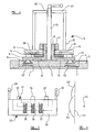
- Referring to the drawings, Figures 1 to 4 illustrate a fitting 1 for use in a motor vehicle. The fitting 1, as can be seen most clearly in Figure 2, takes the form of a seat and comprises a
support 2 which supports the seat-part of the fitting above aplatform 3. As will become clear from the following description the fitting 1 may move laterally relative to theplatform 3 and the seat part may move rotationally about a vertical axis defined by thesupport 2. - The
platform 3 is provided with two parallel transversely extendingchannels 4 of "dovetail" shape formed in the upper surface of theplatform 3. Theplatform 3 is in the form of a plate, which is received within a surroundingframe 5. Theframe 5 is configured to be secured to the floor of a vehicle such as a bus or ambulance. Thechannels 4 are formed in the upper surface of theplatform plate 3. Theplatform plate 3 carries, at each end of each of the dovetail-shaped grooves 4, a roller orguide 6, which extends to arecess 7 provided in the under-surface of theplatform plate 5. Therecess 7 extends across the under surface of theplatform plate 3 to the other roller orguide 6. The rollers orguides 6 and therecesses 7 are provided to accommodate a cover-band as will be described below. - The
support 2 includes a base assembly to rest on theplatform 3, the base assembly comprising alower plate 8. Depending from the under-surface of thelower plate 8 aredovetail elements 8 which are received within the dovetail-shaped channels 4. Also formed in the under-surface of thelower plate 8 are bearingchambers 10 which contain roller bearings, the axes of the roller bearings being perpendicular to the axes of thedovetail elements 9, to facilitate rolling the support across the platform in a direction parallel with the axes of thelongitudinal dovetail channels 4. - In a modified embodiment, instead of roller bearings being provided low-friction devices such as, polytetrafluoraethylene pads are provided to facilitate lateral movement of the base assembly across the platform.
- A threaded boss 11 extends upwardly from the centre of the
base plate 8, there being an axial bore extending through the boss and the base plate. - Surrounding the threaded boss and resting on top of the lower plate is a
support ring 12, and located about the periphery of thesupport ring 12 are a plurality ofspacer collars 13. Resting on top of thesupport ring 12 and thespacer collars 13 is anupper plate 14, theupper plate 14 having a central aperture which surrounds a threaded boss 11. Theupper plate 14 is apertured above each of thecollars 13 to expose the hollow interiors of the collars (as can be seen in Figure 7). - A principal component of the
support 2 is a support column, the main part of which comprises a verticaltubular element 15. The lower end of thetubular element 15 is closed with alower closure plate 16. The periphery of theclosure plate 16 forms a flange extending outwardly beyond thetubular element 15. Theclosure plate 16 has a central aperture which accommodates the threaded boss 11. Anut 17 within the interior of thetubular element 15 secures theclosure plate 16 to the threaded boss 11. The under-surface of theclosure plate 16 is provided with anannular groove 19, which surrounds the aperture in the plate, a series ofball bearings 20 being retained within the groove and being trapped between the lower surface of theclosure plate 19 and the upper surface of theupper plate 14 thus forming a bearing which enables thetubular element 15 to rotate relative to the base assembly. Thenut 17 is tightened to such an extent that there is minimal play between thetubular element 15 and the base assembly while permitting thetubular element 15 to rotate relatively freely with reference to the base assembly. - It is to be appreciated that the
support ring 12 and the supportingcollars 13 located between thelower plate 8 and theupper plate 14 provide support for theupper plate 14 so that theupper plate 14 does not become distorted as a consequence of the forces applied thereto by theball bearings 20. - The upper end of the
tubular element 15 is closed with aclosure plate 21, theclosure plate 21 having a centrally located threadedbore 22. A threadedshaft 23 engages the threaded bore 22 and is provided, at is upper end (which projects above the closure plate 21) with an actuating handle. The lower end of the threadedshaft 23 is located adjacent the lower surface of thelower plate 9 of the base assembly, just above theplatform 3. - As will become clearer from the following description the threaded
shaft 23 forms a clamping mechanism which can be actuated to clamp the base assembly at a selected lateral position by bringing the dependingdove tail elements 8 into engagement with the dove tail shaped channels, thus generating a friction effect which will prevent lateral movement of the base assembly. - At approximately mid point of the vertical
tubular element 15, a transversely extendingshaft 24 is provided which extends to either side of the tubular element. Mounted on each end of the shaft is awinch drum 25, eachwinch drum 25 having, immediately adjacent thetubular element 15, atoothed flange 26. - A
foot pedal 27, illustrated in Figure 5, is provided. Thefoot pedal 27 has arectangular foot plate 28, thefoot plate 28 carrying, at either edge thereof, respectively forwardly directedarms arms shaft 24 which are outboard of the winch drums 25. - Contained within the rectangular foot pedal (see Figure 5) is a spring-biased
dog element 31. Thefoot plate 28 of thefoot pedal 27 is of hollow or "sandwich" construction, and contains within its interior a generally "E"-shapeddog element 31, the element being located so that two protrudingarms toothed flanges 26 provided on the winch drums 25, and a centrally locatedcam follower 34. The dog member is resiliently biased by threesprings foot plate 28 so that thedogs cam follower 34 extend out of the edge of thefoot plate 28 closest to thetubular element 15. - A
spring arrangement 38 is provided to bias the foot pedal upwardly. In the illustrated embodiment the spring is a tension spring extending from thefoot pedal 27 to thetubular element 15. In another embodiment the spring is a torsion spring, for example a spring which has a coiled part which extends around theshaft 24. - A pair of
ratchet elements 39 are provided pivotally mounted on ashaft 40 which extends transversely of thetubular element 15 at a position above theshaft 24. The tworatchet elements 39 are interconnected by acontrol hoop 41 which partially surrounds thetubular element 15, and is actuated by an actuatingstrap 42. - The
tubular element 15 is provided with a cam which is centrally located to be in alignment with thecam follower 34. The cam, shown ascam 43, is in the form of a vertically extending plate centrally located on the exterior of thetubular element 15, between the winch drums 25. Thecam 43 has afirst portion 44 which has a centre of curvature coincident with the axis of theshaft 24, and a further, upper portion, which projects beyond the curvature of the first portion of the cam. - Attached to the winch drums 25 are two lengths of
belt 46 each of which terminates with anappropriate karabiner 47. Each length ofbelt 46, as it leaves the winch drum, passes through a belt guide provided at a forward edge of thelower closure plate 16, as can be seen in Figure 1. The lengths of belt are thus guided forwardly substantially at floor level. - The upper part of the vertical
tubular element 15 carries two outwardly directed support struts 48, 49, each of which carries, at its outer end, a respective forwardly directedside arm side arms - At this stage it is to be understood that the
entire support 2, carrying the seat-like structure (which will be described below) can move laterally relative to theplatform 3 and the seat structure can rotate about a central vertical axis. In order to minimise the risk of thedovetail channels 4 becoming blocked in any way, (which might hinder the lateral movement) cover-bands 52 are provided which extend, from one side of the base assembly, along the top of each dovetail-shapedchannel 4, around the roller orguide 6 provided at the end of the channel, through therecess 7 provided on the under-surface of the platform plate, around the roller orguide 6 provided at the other end of the dovetail-shaped groove, and back to the other side of the base assembly. - It is thus to be appreciated that, as the base assembly moves across the platform, the cover-band will also move, but the cover-band will always cover the open mouth of the respective dovetail-shaped channel in the
platform plate 3. - Mounted on an extending flange formed by the
closure plate 16, provided at the lower end of the verticaltubular element 15 is a see-saw mountedlever 53, supported on ashaft 54 which is carried by two spaced-apartupstanding lugs 55. Afoot pedal 56 is provided at one end of the see-saw lever 53 and aspring 57 is provided to bias the foot pedal upwardly. The other end of the see-saw lever 53 carries aplunger 58 which extends downwardly through anaperture 59 provided in theclosure plate 16, the plunger being positioned to be aligned (in different rotational positions of the tubular element 15) with the hollow interiors of thespacing collars 13, which are accessible through the apertures provided in theupper plate 14 of the base assembly. - Consequently it is to be understood that, initially, the
plunger 58 will be engaged within the interior of aspecific spacer collar 13, thus preventing rotation of thetubular element 15. However, upon depressing thefoot pedal 56 theplunger 58 will be raised to such an extent that the plunger becomes disengaged from the interior of thespacer collar 13, and then it will be possible to rotate thetubular element 15, for example by 90°, thus realigning theplunger 58 with anotherspace collar 13. After the foot pedal is released the plunger will be accommodated within the interior of thespacer collar 13 that it becomes aligned with, thus again preventing rotation of thetubular element 15. - Whilst it is envisaged that four evenly spaced hollow spacer collars will be provided, thus giving the
tubular element 4 possible relative rotational positions, more (or fewer) spacer elements may be provided if desired. - Consequently it is to be understood that by actuating the foot pedal and applying an appropriate manual rotational force to the fitting 1, the fitting may be rotated about a vertical axis, and will then be locked in a new position.
- In an initial condition of the support, the threaded
shaft 25 will be tightened with the handle provided at the upper end of theshaft 23 so that the shaft firmly engages the upper surface of theplatform plate 3 and so that, consequently, an upward force is applied, by thetubular element 15 to thelower closure plate 16 and thus, by engagement of thenut 17 with the threaded boss 11, an upward force is applied to thelower plate 8 thus drawing thedovetail elements 10 upwardly into firm engagement with the converging upper part of thedovetail grooves 4, thus preventing lateral movement of thesupport 2. Here it is to be appreciated that by operating the handle to withdraw the threadedshaft 23 from engagement with theplatform 5, effectively thedovetail elements 4 will be lowered slightly within thedovetail channels 4 and the rollers provided in the bearingchambers 10 formed on the under-surface of thelower plate 8 will engage the upper surface of theplatform plate 3, thus enabling thesupport 2 and the seat-like structure carried on thesupport 2 to be moved laterally across the platform in an easy manner. When thesupport 2 is in a new, desired position, the handle provided on the threadedshaft 23 may be actuated so that the threadedshaft 23 is again brought into firm engagement with theplatform plate 3, thus again bringing thedovetail elements 10 into firm engagement with the converging part of thedovetail grooves 4 and again locking the support firmly in position. - The seat-like structure is of a known form and corresponds with the seat-like structure disclosed in
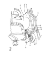
WO 2004/041586 , which is incorporated herein by reference. - The seat-like structure comprises a squab 60 and a seat back
assembly 61. The squab 60 is releasably connected to the rest of the fitting so that the squab may, when desired, be placed in position to form the squab of the seat and, when desired, may be removed, so that the fitting is then squab-less. The space in front of the backrest is then "empty" and is not obstructed by the squab. - The squab 60 has two rearwardly extending
support arms engagement finger rod 66, having ends 67,68 which project beyond the support arms to form mounting lugs. - Seat-squab-
finger engaging formations 69 are provided on the inner side of each of theside arms hook unit 70. Thefingers formations 69 and thehooks 70 may be engaged with the projectinglugs fingers formations 70.. - The
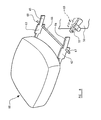
side arms upper linkage 72 and alower linkage 73 which support a padded backrest 74. An over-dead-centre handle-actuateddrive mechanism 75 is provided which can be actuated to drive the padded backrest unit 74 forwardly or rearwardly relative to theframe 70. The position of the seat back unit may thus be adjusted as desired. - The padded
backrest unit 74 has a greater width at the top, than it does at a position beneath the top. - The seat back carries two
safety belts - The described fitting may be used as a conventional seat or may be used in conjunction with a wheelchair.
- If the fitting is to be used as a conventional seat, the lateral and rotational position of the fitting is adjusted, in the manner described, and the padded back
rest 74 is positioned appropriate relative to the squab 60. The seat may then be used by a seat occupant, and a seat occupant may be restrained by the twosafety belts - If the seat is to be used by a wheelchair user, initially the squab 60 is removed. The wheelchair is then positioned in front of the
backrest 3. TheKarabiners 47 on thestraps 46 are attached to appropriate parts of the wheelchair. Thefoot pedal 27 is then driven downwardly. The springbiased dogs toothed flanges 26 on the winch drums 25, thus causing winch drums to rotate. As the winch drums rotate so theratchets 39 effect a ratcheting movement across the ratchet teeth provided on thetoothed flanges 26. - When the foot pedal is totally depressed, the foot pedal is released. The
spring arrangement 38 will then tend to draw the foot pedal back up to its initial position. As the foot pedal effects this movement thedogs ratchets 39. - This operation has served to draw in part of the
belts 46, which extend to theKarabiners 47. Thus the wheelchair is drawn into a position in which the back of the wheelchair is up against the paddedbackrest 73. It is to be appreciated that the foot pedal may need to be depressed several times in order to draw in the entire length of thebelt 46, and to draw the wheelchair tightly up against the fitting. - When the backrest of the wheelchair is pressed up against the padded
backrest 73, thesafety belts - It is to be appreciated that even if the wheelchair is relatively narrow the wheelchair may be accommodated against the backrest because the handles provided on the backrest of the wheelchair will pass to either side of the relatively narrow lower part of the
backrest 73 of the fitting. - When the wheelchair user wishes to leave the vehicle, the foot pedal may be pressed down slightly to relieve the tension applied to the
ratchet 39 by thetooth flanges 26 of the winch drums 25, and then the actuatingstrap 42 may be pulled upwardly so that thecontrol hoop 41 pulls theratchet teeth 39 upwardly thus disengaging theratchets 39 from the ratchet teeth. The winch drums 25 may still, however, not be free to rotate due to the engagement of thedogs foot pedal 27 with the ratchet teeth. If the foot pedal, however, is pushed upwardly from its position of rest, the cam follower will follow theuppermost part 45 of thecam 43, and this will serve to force thedog member 31 back into thefoot plate 28, thus disengaging thedogs toothed flanges 26 of the winch drums 25. The winch drums may now rotate freely to pay out thestraps 46. - It is to be appreciated that the fitting as described above may be found to be extremely versatile. The fitting may be adjusted between a multitude of positions and may be used by able-bodied people and also by wheelchair users. If the fitting is used within a vehicle which has a compact interior, it will be possible for the squab of the fitting to be removed, for the fitting to be rotated and for the fitting to be moved laterally, for example up adjacent one side of the vehicle, so that the fitting, when in this form, provides a very minimum of obstruction to personnel entering or leaving the vehicle. It would be possible, for example, with the fitting in this condition to manoeuvre a wheelchair past the fitting so that the wheelchair is in front of the fitting. The fitting may then be moved laterally away from the side wall of the vehicle towards the centre of the vehicle, and the fitting may be rotated so that the fitting is then in a ideal position for use by the wheelchair user.
- It is to be understood that while, in the described embodiment, the squab is removable from the fitting, in an alternative embodiment the squab may simply be movable between an extended operative position and a retracted position in which it does not obstruct the space in front of the backrest.
- The
backrest 74 may move forwardly if the fitting is to be used with an electric wheelchair having a battery housing in a lower part of the back of the wheelchair. The protruding battery housing may be accommodated, consequently, beneath the lowermost part of the backrest, and the backrest may firmly engage the rearmost part of the wheelchair behind the spine of the occupant of the wheelchair. - It is to be appreciated that whilst the fitting may be used with a relatively narrow wheelchair, because of the relatively narrow width of the lowermost part of the backrest, nevertheless, guides for the two seat belts may be located at the uppermost part of the backrest and may be appropriately spaced apart for use by an adult.
- When used in this specification and claims, the terms "comprises" and "comprising" and variations thereof mean that the specified features, steps or integers are included. The terms are not to be interpreted to exclude the presence of other features, steps or components.
- The features disclosed in the foregoing description, or the following claims, or the accompanying drawings, expressed in their specific forms or in terms of a means for performing the disclosed function, or a method or process for attaining the disclosed result, as appropriate, may, separately, or in any combination of such features, be utilised for realising the invention in diverse forms thereof.
Claims (12)
- A fitting for a motor vehicle, the fitting comprising a support, the support being provided with a seat squab and a backrest, the squab being moveable from an initial position in which the squab projects forwardly from the support, to a position in which the squab does not obstruct the space in front of the backrest, the support being rotatably mounted relative to base assembly, the base assembly being mounted for lateral movement.
- A fitting according to Claim 1, wherein the base assembly is mounted on a platform, there being low friction or rolling elements to enable the base assembly to move relative to the platform, the base assembly carrying depending elements, the depending elements being accommodated within corresponding channels formed in the platform.
- A fitting according to Claim 2, wherein cover strips are provided to cover the channels in the platform, the cover strips passing round guide provided at each end of the channel in the platform and being accommodated in a recess extending beneath the platform.
- A fitting according to any one of the preceding Claims, wherein the base assembly defines a plurality of radially spaced locator recesses, the support carrying a plunger selectively engageable with a recess when the support is in a selected are of a plurality of rotational spaced positions.
- A fitting according to Claim 4, wherein the plunger is mounted on a foot pedal actuated mechanism to withdraw the plunger from a said recess.
- A fitting according to any one of the preceding Claims, wherein the support comprises a tubular element, the lower end of the tubular element being provided with a bearing to support the tubular element rotational relative to the base assembly, the upper end of the tubular element carrying the squab and the backrest.
- A fitting according to any one of the preceding Claims, wherein the squab is removably mounted to the rest of the fitting.
- A fitting according to any one of the preceding Claims, wherein the backrest comprises a backrest element which is carried by a support frame and which is moveable forwardly relative to the support frame.
- A fitting according to any one of the preceding Claims, wherein the backrest is relatively wide at the top, but has a lesser width at a lower position.
- A fitting according to any one of the preceding Claims having a clamping mechanism to clamp the base assembly in a selected lateral position.
- A fitting according to Claim 2 or any one of Claims 3 to 9 dependent thereon, wherein a clamping mechanism is provided to bring the depending elements into engagement with the channel to clamp the base assembly in a selected lateral position.
- A fitting according to any one of the preceding Claims provided with a winch, the winch comprising at least one drum, part of the drum forming a flange provided with peripheral ratchet teeth, there being a ratchet to engage the ratchet teeth, there being a foot pedal, the foot pedal being spring biased to an initial position, the foot pedal incorporating a dog resiliently biased into engagement with the ratchet teeth, the foot pedal being actuable against said spring bias to rotate the drum when the dog is in engagement with the ratchet teeth, the dog forming part of a dog member, another part of the dog member forming a cam follower, there being a cam positioned to engage the cam follower such that on elevation of the foot pedal above a predetermined position the cam follower will engage the cam and retract the dog from the teeth.
Applications Claiming Priority (1)
| Application Number | Priority Date | Filing Date | Title |
|---|---|---|---|
| GB0509086A GB2425721A (en) | 2005-05-04 | 2005-05-04 | Vehicle seat with lateral and rotational movement with detachable squab |
Publications (2)
| Publication Number | Publication Date |
|---|---|
| EP1736356A1 true EP1736356A1 (en) | 2006-12-27 |
| EP1736356B1 EP1736356B1 (en) | 2008-04-30 |
Family
ID=34674312
Family Applications (1)
| Application Number | Title | Priority Date | Filing Date |
|---|---|---|---|
| EP06009049A Active EP1736356B1 (en) | 2005-05-04 | 2006-05-02 | A vehicle fitting |
Country Status (6)
| Country | Link |
|---|---|
| US (1) | US20060250011A1 (en) |
| EP (1) | EP1736356B1 (en) |
| AT (1) | ATE393719T1 (en) |
| AU (1) | AU2006201874A1 (en) |
| DE (1) | DE602006001036D1 (en) |
| GB (1) | GB2425721A (en) |
Families Citing this family (7)
| Publication number | Priority date | Publication date | Assignee | Title |
|---|---|---|---|---|
| GB2430356B (en) | 2005-09-22 | 2009-11-04 | Nmi Safety Systems Ltd | A seating arrangement |
| US8919882B2 (en) * | 2008-10-06 | 2014-12-30 | Black Mountain Industries, Inc. | Soldier platform system |
| DK179512B1 (en) * | 2017-04-04 | 2019-02-04 | Maskinfabrik Dahl Engineering V/Claus Dahl Pedersen | Height adjustable wheelchair docking system |
| DE102017007418B4 (en) * | 2017-08-05 | 2021-11-04 | Audi Ag | Motor vehicle with at least one vehicle seat |
| WO2020263807A1 (en) * | 2019-06-25 | 2020-12-30 | The Braun Corporation | Wheelchair docking system and method thereof |
| USD1018268S1 (en) | 2021-08-16 | 2024-03-19 | The Braun Corporation | Wheelchair coupling mechanism |
| US20230172776A1 (en) * | 2021-12-08 | 2023-06-08 | Toyota Boshoku Kabushiki Kaisha | Wheelchair restraint apparatus |
Citations (3)
| Publication number | Priority date | Publication date | Assignee | Title |
|---|---|---|---|---|
| EP0972671A1 (en) * | 1997-04-03 | 2000-01-19 | Toyota Shatai Kabushiki Kaisha | Vehicular rotary seat |
| WO2002091979A1 (en) * | 2001-05-14 | 2002-11-21 | Nmi Safety Systems Limited | Restraint for restraining a wheelchair occupant in a vehicle |
| WO2004041586A1 (en) * | 2002-11-08 | 2004-05-21 | Nmi Safety Systems Ltd | A vehicle fitting |
Family Cites Families (9)
| Publication number | Priority date | Publication date | Assignee | Title |
|---|---|---|---|---|
| US2309735A (en) * | 1940-04-26 | 1943-02-02 | Arthur L Koch | Vehicle construction |
| US3632055A (en) * | 1970-01-13 | 1972-01-04 | Robbins Seat Belt Co | Seat belt retractor |
| US4561621A (en) * | 1983-08-17 | 1985-12-31 | Milsco Manufacturing Company | Tiltable vehicle seat for backhoes or the like |
| US4834452A (en) * | 1988-07-05 | 1989-05-30 | Goodrich Grover G | Swivel seat and frame |
| US5374102A (en) * | 1993-03-30 | 1994-12-20 | Baultar Inc. | Chair assembly for vehicle |
| JPH09207634A (en) * | 1996-01-30 | 1997-08-12 | Hitachi Constr Mach Co Ltd | Locking mechanism for rotatable seat |
| WO1999017953A1 (en) * | 1997-10-02 | 1999-04-15 | Johnson Controls Technology Company | Flexible seat system |
| KR20030071182A (en) * | 2002-02-28 | 2003-09-03 | 주식회사 한일 | Turning table assembly of seat for vehicle |
| GB2430356B (en) * | 2005-09-22 | 2009-11-04 | Nmi Safety Systems Ltd | A seating arrangement |
-
2005
- 2005-05-04 GB GB0509086A patent/GB2425721A/en active Pending
-
2006
- 2006-05-02 AT AT06009049T patent/ATE393719T1/en not_active IP Right Cessation
- 2006-05-02 EP EP06009049A patent/EP1736356B1/en active Active
- 2006-05-02 DE DE602006001036T patent/DE602006001036D1/en not_active Expired - Fee Related
- 2006-05-03 AU AU2006201874A patent/AU2006201874A1/en not_active Abandoned
- 2006-05-04 US US11/417,777 patent/US20060250011A1/en not_active Abandoned
Patent Citations (3)
| Publication number | Priority date | Publication date | Assignee | Title |
|---|---|---|---|---|
| EP0972671A1 (en) * | 1997-04-03 | 2000-01-19 | Toyota Shatai Kabushiki Kaisha | Vehicular rotary seat |
| WO2002091979A1 (en) * | 2001-05-14 | 2002-11-21 | Nmi Safety Systems Limited | Restraint for restraining a wheelchair occupant in a vehicle |
| WO2004041586A1 (en) * | 2002-11-08 | 2004-05-21 | Nmi Safety Systems Ltd | A vehicle fitting |
Also Published As
| Publication number | Publication date |
|---|---|
| GB0509086D0 (en) | 2005-06-08 |
| GB2425721A (en) | 2006-11-08 |
| US20060250011A1 (en) | 2006-11-09 |
| ATE393719T1 (en) | 2008-05-15 |
| AU2006201874A1 (en) | 2006-11-23 |
| DE602006001036D1 (en) | 2008-06-12 |
| EP1736356B1 (en) | 2008-04-30 |
Similar Documents
| Publication | Publication Date | Title |
|---|---|---|
| EP1736356B1 (en) | A vehicle fitting | |
| US7641257B2 (en) | Seating arrangement | |
| US9403448B1 (en) | Transfer seat base with pedal guard assembly | |
| US3189368A (en) | Wheel chair driver attachment | |
| US6347688B1 (en) | Wheel chair rollback stop | |
| US4455046A (en) | Safety device for the vehicular transport of a person travelling in a wheelchair | |
| EP3446919B1 (en) | Foldable manual child safety seat | |
| US5762593A (en) | Exercise apparatus for the disabled | |
| CA2936983A1 (en) | Smart-rollator with everyday life adapted chassis, fall detection system, automatic braking and anti-roll back systems, manufacturing method and usages thereof | |
| US5486016A (en) | Wheel assembly for a wheelchair, incorporating a change speed hub | |
| JPH07255559A (en) | Seat device for vehicle | |
| JP2017196408A (en) | Coupling mechanism between wheelchair and car seat | |
| EP3494943B1 (en) | Manual wheel-attached movable body | |
| US7651167B2 (en) | Vehicle fitting | |
| KR101144870B1 (en) | Apparatus for forward and backward movement of car headrests | |
| EP3846761B1 (en) | A tilt lock mechanism for a tilting wheelchair seat | |
| US20030098568A1 (en) | Safety locking wheelchair | |
| AU2003279467B2 (en) | A vehicle fitting | |
| JP4787378B1 (en) | wheelchair | |
| US20230105325A1 (en) | Anti-Rollback Device for Use with a Collapsible Wheelchair | |
| JP2005177333A (en) | Chair with function of stand assistance | |
| CH698591B1 (en) | Apparatus for supporting and holding back of a wheelchair in a vehicle. | |
| JP2024007921A (en) | walking car | |
| JP2015104655A (en) | Auxiliary tool for overcoming step and wheelchair | |
| JP3183821U (en) | Wheelchair safety device |
Legal Events
| Date | Code | Title | Description |
|---|---|---|---|
| PUAI | Public reference made under article 153(3) epc to a published international application that has entered the european phase |
Free format text: ORIGINAL CODE: 0009012 |
|
| AK | Designated contracting states |
Kind code of ref document: A1 Designated state(s): AT BE BG CH CY CZ DE DK EE ES FI FR GB GR HU IE IS IT LI LT LU LV MC NL PL PT RO SE SI SK TR |
|
| AX | Request for extension of the european patent |
Extension state: AL BA HR MK YU |
|
| 17P | Request for examination filed |
Effective date: 20070125 |
|
| 17Q | First examination report despatched |
Effective date: 20070222 |
|
| AKX | Designation fees paid |
Designated state(s): AT BE BG CH CY CZ DE DK EE ES FI FR GB GR HU IE IS IT LI LT LU LV MC NL PL PT RO SE SI SK TR |
|
| GRAP | Despatch of communication of intention to grant a patent |
Free format text: ORIGINAL CODE: EPIDOSNIGR1 |
|
| GRAS | Grant fee paid |
Free format text: ORIGINAL CODE: EPIDOSNIGR3 |
|
| GRAA | (expected) grant |
Free format text: ORIGINAL CODE: 0009210 |
|
| AK | Designated contracting states |
Kind code of ref document: B1 Designated state(s): AT BE BG CH CY CZ DE DK EE ES FI FR GB GR HU IE IS IT LI LT LU LV MC NL PL PT RO SE SI SK TR |
|
| REG | Reference to a national code |
Ref country code: GB Ref legal event code: FG4D |
|
| REG | Reference to a national code |
Ref country code: CH Ref legal event code: EP |
|
| REG | Reference to a national code |
Ref country code: IE Ref legal event code: FG4D Free format text: LANGUAGE OF EP DOCUMENT: FRENCH |
|
| REF | Corresponds to: |
Ref document number: 602006001036 Country of ref document: DE Date of ref document: 20080612 Kind code of ref document: P |
|
| PG25 | Lapsed in a contracting state [announced via postgrant information from national office to epo] |
Ref country code: SI Free format text: LAPSE BECAUSE OF FAILURE TO SUBMIT A TRANSLATION OF THE DESCRIPTION OR TO PAY THE FEE WITHIN THE PRESCRIBED TIME-LIMIT Effective date: 20080430 |
|
| NLV1 | Nl: lapsed or annulled due to failure to fulfill the requirements of art. 29p and 29m of the patents act | ||
| PG25 | Lapsed in a contracting state [announced via postgrant information from national office to epo] |
Ref country code: ES Free format text: LAPSE BECAUSE OF FAILURE TO SUBMIT A TRANSLATION OF THE DESCRIPTION OR TO PAY THE FEE WITHIN THE PRESCRIBED TIME-LIMIT Effective date: 20080810 Ref country code: BG Free format text: LAPSE BECAUSE OF FAILURE TO SUBMIT A TRANSLATION OF THE DESCRIPTION OR TO PAY THE FEE WITHIN THE PRESCRIBED TIME-LIMIT Effective date: 20080730 Ref country code: FI Free format text: LAPSE BECAUSE OF FAILURE TO SUBMIT A TRANSLATION OF THE DESCRIPTION OR TO PAY THE FEE WITHIN THE PRESCRIBED TIME-LIMIT Effective date: 20080430 Ref country code: NL Free format text: LAPSE BECAUSE OF FAILURE TO SUBMIT A TRANSLATION OF THE DESCRIPTION OR TO PAY THE FEE WITHIN THE PRESCRIBED TIME-LIMIT Effective date: 20080430 Ref country code: PT Free format text: LAPSE BECAUSE OF FAILURE TO SUBMIT A TRANSLATION OF THE DESCRIPTION OR TO PAY THE FEE WITHIN THE PRESCRIBED TIME-LIMIT Effective date: 20080930 |
|
| PG25 | Lapsed in a contracting state [announced via postgrant information from national office to epo] |
Ref country code: AT Free format text: LAPSE BECAUSE OF FAILURE TO SUBMIT A TRANSLATION OF THE DESCRIPTION OR TO PAY THE FEE WITHIN THE PRESCRIBED TIME-LIMIT Effective date: 20080430 Ref country code: PL Free format text: LAPSE BECAUSE OF FAILURE TO SUBMIT A TRANSLATION OF THE DESCRIPTION OR TO PAY THE FEE WITHIN THE PRESCRIBED TIME-LIMIT Effective date: 20080430 Ref country code: LV Free format text: LAPSE BECAUSE OF FAILURE TO SUBMIT A TRANSLATION OF THE DESCRIPTION OR TO PAY THE FEE WITHIN THE PRESCRIBED TIME-LIMIT Effective date: 20080430 |
|
| PG25 | Lapsed in a contracting state [announced via postgrant information from national office to epo] |
Ref country code: IS Free format text: LAPSE BECAUSE OF FAILURE TO SUBMIT A TRANSLATION OF THE DESCRIPTION OR TO PAY THE FEE WITHIN THE PRESCRIBED TIME-LIMIT Effective date: 20080830 Ref country code: MC Free format text: LAPSE BECAUSE OF NON-PAYMENT OF DUE FEES Effective date: 20080531 |
|
| PG25 | Lapsed in a contracting state [announced via postgrant information from national office to epo] |
Ref country code: EE Free format text: LAPSE BECAUSE OF FAILURE TO SUBMIT A TRANSLATION OF THE DESCRIPTION OR TO PAY THE FEE WITHIN THE PRESCRIBED TIME-LIMIT Effective date: 20080430 Ref country code: SE Free format text: LAPSE BECAUSE OF FAILURE TO SUBMIT A TRANSLATION OF THE DESCRIPTION OR TO PAY THE FEE WITHIN THE PRESCRIBED TIME-LIMIT Effective date: 20080731 Ref country code: CZ Free format text: LAPSE BECAUSE OF FAILURE TO SUBMIT A TRANSLATION OF THE DESCRIPTION OR TO PAY THE FEE WITHIN THE PRESCRIBED TIME-LIMIT Effective date: 20080430 Ref country code: DK Free format text: LAPSE BECAUSE OF FAILURE TO SUBMIT A TRANSLATION OF THE DESCRIPTION OR TO PAY THE FEE WITHIN THE PRESCRIBED TIME-LIMIT Effective date: 20080430 Ref country code: LT Free format text: LAPSE BECAUSE OF FAILURE TO SUBMIT A TRANSLATION OF THE DESCRIPTION OR TO PAY THE FEE WITHIN THE PRESCRIBED TIME-LIMIT Effective date: 20080430 |
|
| EN | Fr: translation not filed | ||
| PG25 | Lapsed in a contracting state [announced via postgrant information from national office to epo] |
Ref country code: BE Free format text: LAPSE BECAUSE OF FAILURE TO SUBMIT A TRANSLATION OF THE DESCRIPTION OR TO PAY THE FEE WITHIN THE PRESCRIBED TIME-LIMIT Effective date: 20080430 Ref country code: SK Free format text: LAPSE BECAUSE OF FAILURE TO SUBMIT A TRANSLATION OF THE DESCRIPTION OR TO PAY THE FEE WITHIN THE PRESCRIBED TIME-LIMIT Effective date: 20080430 Ref country code: RO Free format text: LAPSE BECAUSE OF FAILURE TO SUBMIT A TRANSLATION OF THE DESCRIPTION OR TO PAY THE FEE WITHIN THE PRESCRIBED TIME-LIMIT Effective date: 20080430 |
|
| PLBE | No opposition filed within time limit |
Free format text: ORIGINAL CODE: 0009261 |
|
| STAA | Information on the status of an ep patent application or granted ep patent |
Free format text: STATUS: NO OPPOSITION FILED WITHIN TIME LIMIT |
|
| 26N | No opposition filed |
Effective date: 20090202 |
|
| PG25 | Lapsed in a contracting state [announced via postgrant information from national office to epo] |
Ref country code: FR Free format text: LAPSE BECAUSE OF FAILURE TO SUBMIT A TRANSLATION OF THE DESCRIPTION OR TO PAY THE FEE WITHIN THE PRESCRIBED TIME-LIMIT Effective date: 20090227 Ref country code: DE Free format text: LAPSE BECAUSE OF NON-PAYMENT OF DUE FEES Effective date: 20081202 |
|
| PG25 | Lapsed in a contracting state [announced via postgrant information from national office to epo] |
Ref country code: IT Free format text: LAPSE BECAUSE OF FAILURE TO SUBMIT A TRANSLATION OF THE DESCRIPTION OR TO PAY THE FEE WITHIN THE PRESCRIBED TIME-LIMIT Effective date: 20080430 |
|
| PG25 | Lapsed in a contracting state [announced via postgrant information from national office to epo] |
Ref country code: LU Free format text: LAPSE BECAUSE OF NON-PAYMENT OF DUE FEES Effective date: 20080502 Ref country code: HU Free format text: LAPSE BECAUSE OF FAILURE TO SUBMIT A TRANSLATION OF THE DESCRIPTION OR TO PAY THE FEE WITHIN THE PRESCRIBED TIME-LIMIT Effective date: 20081101 Ref country code: CY Free format text: LAPSE BECAUSE OF FAILURE TO SUBMIT A TRANSLATION OF THE DESCRIPTION OR TO PAY THE FEE WITHIN THE PRESCRIBED TIME-LIMIT Effective date: 20080430 |
|
| PG25 | Lapsed in a contracting state [announced via postgrant information from national office to epo] |
Ref country code: TR Free format text: LAPSE BECAUSE OF FAILURE TO SUBMIT A TRANSLATION OF THE DESCRIPTION OR TO PAY THE FEE WITHIN THE PRESCRIBED TIME-LIMIT Effective date: 20080430 |
|
| PG25 | Lapsed in a contracting state [announced via postgrant information from national office to epo] |
Ref country code: GR Free format text: LAPSE BECAUSE OF FAILURE TO SUBMIT A TRANSLATION OF THE DESCRIPTION OR TO PAY THE FEE WITHIN THE PRESCRIBED TIME-LIMIT Effective date: 20080731 |
|
| REG | Reference to a national code |
Ref country code: CH Ref legal event code: PL |
|
| PG25 | Lapsed in a contracting state [announced via postgrant information from national office to epo] |
Ref country code: CH Free format text: LAPSE BECAUSE OF NON-PAYMENT OF DUE FEES Effective date: 20100531 Ref country code: LI Free format text: LAPSE BECAUSE OF NON-PAYMENT OF DUE FEES Effective date: 20100531 |
|
| PGFP | Annual fee paid to national office [announced via postgrant information from national office to epo] |
Ref country code: GB Payment date: 20230323 Year of fee payment: 18 |
|
| P01 | Opt-out of the competence of the unified patent court (upc) registered |
Effective date: 20230602 |
|
| P02 | Opt-out of the competence of the unified patent court (upc) changed |
Effective date: 20230616 |
|
| PGFP | Annual fee paid to national office [announced via postgrant information from national office to epo] |
Ref country code: IE Payment date: 20230412 Year of fee payment: 18 |