EP1736277A2 - Spindle device with through coolant and closed spindle cooling circuit running through a rotary coupling - Google Patents
Spindle device with through coolant and closed spindle cooling circuit running through a rotary coupling Download PDFInfo
- Publication number
- EP1736277A2 EP1736277A2 EP06010514A EP06010514A EP1736277A2 EP 1736277 A2 EP1736277 A2 EP 1736277A2 EP 06010514 A EP06010514 A EP 06010514A EP 06010514 A EP06010514 A EP 06010514A EP 1736277 A2 EP1736277 A2 EP 1736277A2
- Authority
- EP
- European Patent Office
- Prior art keywords
- spindle
- channel
- coolant
- spindle device
- seal
- Prior art date
- Legal status (The legal status is an assumption and is not a legal conclusion. Google has not performed a legal analysis and makes no representation as to the accuracy of the status listed.)
- Granted
Links
- 239000002826 coolant Substances 0.000 title claims abstract description 52
- 238000001816 cooling Methods 0.000 title claims abstract description 46
- 230000008878 coupling Effects 0.000 title 1
- 238000010168 coupling process Methods 0.000 title 1
- 238000005859 coupling reaction Methods 0.000 title 1
- 238000007789 sealing Methods 0.000 description 5
- 238000005461 lubrication Methods 0.000 description 3
- 238000010276 construction Methods 0.000 description 2
- 230000006866 deterioration Effects 0.000 description 2
- 238000003801 milling Methods 0.000 description 2
- 230000002411 adverse Effects 0.000 description 1
- 238000011109 contamination Methods 0.000 description 1
- 230000006735 deficit Effects 0.000 description 1
- 230000000694 effects Effects 0.000 description 1
- 238000000227 grinding Methods 0.000 description 1
- 238000009434 installation Methods 0.000 description 1
- 238000002955 isolation Methods 0.000 description 1
- 239000003507 refrigerant Substances 0.000 description 1
Images


Classifications
-
- B—PERFORMING OPERATIONS; TRANSPORTING
- B23—MACHINE TOOLS; METAL-WORKING NOT OTHERWISE PROVIDED FOR
- B23Q—DETAILS, COMPONENTS, OR ACCESSORIES FOR MACHINE TOOLS, e.g. ARRANGEMENTS FOR COPYING OR CONTROLLING; MACHINE TOOLS IN GENERAL CHARACTERISED BY THE CONSTRUCTION OF PARTICULAR DETAILS OR COMPONENTS; COMBINATIONS OR ASSOCIATIONS OF METAL-WORKING MACHINES, NOT DIRECTED TO A PARTICULAR RESULT
- B23Q11/00—Accessories fitted to machine tools for keeping tools or parts of the machine in good working condition or for cooling work; Safety devices specially combined with or arranged in, or specially adapted for use in connection with, machine tools
- B23Q11/12—Arrangements for cooling or lubricating parts of the machine
- B23Q11/126—Arrangements for cooling or lubricating parts of the machine for cooling only
- B23Q11/127—Arrangements for cooling or lubricating parts of the machine for cooling only for cooling motors or spindles
-
- B—PERFORMING OPERATIONS; TRANSPORTING
- B23—MACHINE TOOLS; METAL-WORKING NOT OTHERWISE PROVIDED FOR
- B23Q—DETAILS, COMPONENTS, OR ACCESSORIES FOR MACHINE TOOLS, e.g. ARRANGEMENTS FOR COPYING OR CONTROLLING; MACHINE TOOLS IN GENERAL CHARACTERISED BY THE CONSTRUCTION OF PARTICULAR DETAILS OR COMPONENTS; COMBINATIONS OR ASSOCIATIONS OF METAL-WORKING MACHINES, NOT DIRECTED TO A PARTICULAR RESULT
- B23Q11/00—Accessories fitted to machine tools for keeping tools or parts of the machine in good working condition or for cooling work; Safety devices specially combined with or arranged in, or specially adapted for use in connection with, machine tools
- B23Q11/10—Arrangements for cooling or lubricating tools or work
- B23Q11/1015—Arrangements for cooling or lubricating tools or work by supplying a cutting liquid through the spindle
- B23Q11/103—Rotary joints specially adapted for feeding the cutting liquid to the spindle
-
- B—PERFORMING OPERATIONS; TRANSPORTING
- B23—MACHINE TOOLS; METAL-WORKING NOT OTHERWISE PROVIDED FOR
- B23Q—DETAILS, COMPONENTS, OR ACCESSORIES FOR MACHINE TOOLS, e.g. ARRANGEMENTS FOR COPYING OR CONTROLLING; MACHINE TOOLS IN GENERAL CHARACTERISED BY THE CONSTRUCTION OF PARTICULAR DETAILS OR COMPONENTS; COMBINATIONS OR ASSOCIATIONS OF METAL-WORKING MACHINES, NOT DIRECTED TO A PARTICULAR RESULT
- B23Q11/00—Accessories fitted to machine tools for keeping tools or parts of the machine in good working condition or for cooling work; Safety devices specially combined with or arranged in, or specially adapted for use in connection with, machine tools
- B23Q11/10—Arrangements for cooling or lubricating tools or work
- B23Q11/1038—Arrangements for cooling or lubricating tools or work using cutting liquids with special characteristics, e.g. flow rate, quality
- B23Q11/1046—Arrangements for cooling or lubricating tools or work using cutting liquids with special characteristics, e.g. flow rate, quality using a minimal quantity of lubricant
-
- Y—GENERAL TAGGING OF NEW TECHNOLOGICAL DEVELOPMENTS; GENERAL TAGGING OF CROSS-SECTIONAL TECHNOLOGIES SPANNING OVER SEVERAL SECTIONS OF THE IPC; TECHNICAL SUBJECTS COVERED BY FORMER USPC CROSS-REFERENCE ART COLLECTIONS [XRACs] AND DIGESTS
- Y02—TECHNOLOGIES OR APPLICATIONS FOR MITIGATION OR ADAPTATION AGAINST CLIMATE CHANGE
- Y02P—CLIMATE CHANGE MITIGATION TECHNOLOGIES IN THE PRODUCTION OR PROCESSING OF GOODS
- Y02P70/00—Climate change mitigation technologies in the production process for final industrial or consumer products
- Y02P70/10—Greenhouse gas [GHG] capture, material saving, heat recovery or other energy efficient measures, e.g. motor control, characterised by manufacturing processes, e.g. for rolling metal or metal working
Definitions
- the invention relates to a spindle device with a housing in which a rotatably driven spindle is mounted, which has an axially displaceable in a spindle shaft pull rod for actuating a tool clamping device, wherein on a side facing away from the tool clamping device of the spindle, a rotary feedthrough for supplying a coolant into the spindle is provided.
- Such a spindle device is known from JP 2000288870 A (Patent Abstracts of Japan).
- a supply of coolant via the pull rod for cooling the spindle is used.
- the coolant is discharged laterally out of the spindle.
- a supply of compressed air at different points of the spindle is necessary to keep the bearings free of contamination and to prevent leakage of coolant.
- Such a spindle design has proven to be susceptible to vibration, especially at high speeds.
- the invention has for its object to provide an improved spindle device which is suitable for high spindle speeds. It should be possible to cool the spindle from the inside regardless of a possible coolant supply to the tool. Furthermore, the most effective cooling of the spindle should be ensured with high reliability in continuous operation.
- a rotary feedthrough which has a rotatably mounted spindle portion, via which the at least one cooling channel is coupled to an inflow opening and a discharge opening for the cooling medium.
- the spindle is penetrated by at least one closed cooling channel, which is coupled via the rotary feedthrough with an inlet opening and a drain opening, a flow through the spindle in the circuit allows, the necessary seals can all be arranged in the rotary feedthrough. This ensures a simple and reliable construction.
- the rotary feedthrough has an independently mounted spindle section, via which the coolant supply and discharge takes place, vibrations can be reduced and leakages minimized.
- the spindle device can be mounted in a simple manner as a complete module on a machine tool.
- this arrangement allows independent supply of a tool driven by the spindle device with coolant, if desired.
- the spindle of the invention is characterized by a very good cooling effect into the front, tool-side area including the foremost bearing point.
- the spindle temperature can be maintained at a maximum of about 30 ° C throughout.
- spindle temperatures of about 50 to 70 ° C expected during operation.
- the spindle start according to the invention can be done much faster than conventional spindles. After only about two minutes, stationary conditions arise at the spindle, whereas in the prior art without spindle internal cooling usually about 15 minutes are required. The thermal expansion of the spindle shaft can be kept within minimal limits.
- any coolant can be used.
- the spindle portion is supported by means of two bearings on a housing of the rotary feedthrough, which is detachably connected to the housing of the spindle device, preferably screwed with it.
- At least one closed cooling channel is provided, which extends eccentrically in the axial direction through the spindle shaft, the pull rod and the spindle portion of the rotary feedthrough.
- This embodiment has the advantage that in this way a coolant supply to all bearing points of the spindle and to the rotor of the drive motor combined with the spindle is made possible, while at the same time an additional possibility for a supply of coolant via the drawbar for an independent coolant supply to the tool.
- each cooling channel has a feed channel coupled to the feed opening and a return channel coupled to the discharge opening, wherein the feed channel and return channel are coupled to one another in the region of a first end of the spindle, preferably connected to one another via a deflection element.
- the at least one cooling channel is sealed against a housing of the rotary feedthrough via a first gap seal.
- a seal over a gap seal has the advantage that it is wear-free, so that disadvantages at high spindle speeds can be avoided.
- the first gap seal is arranged downstream of a contact seal, preferably in the form of a lip seal.
- the contact seal via a pressure channel so with a Pressure medium, preferably with air, acted upon, that the contact seal with driven spindle is non-contact and is sealed by the pressure medium, while at standstill of the spindle and switched-off pressure medium, a seal via the contact seal.
- This embodiment has the advantage that a completely non-contact seal is ensured during the operation of the spindle, while a seal on the contact seal takes place at standstill of the spindle and switched-off pressure medium.
- the pressure channel is sealed against a bearing by a second gap seal.
- the pressure channel is coupled according to a further embodiment of the invention with a leakage return, can be discharged via the leaking from the first gap seal leaks of the coolant.
- the second gap seal is connected on the bearing side to a relief channel, via which pressure medium emerging via the second gap seal can be discharged.
- the rotary feedthrough on a housing which is connected to the housing of the spindle and in which a central receptacle for guiding the pull rod is rotatably mounted.
- the rotary feedthrough can be constructed as a separate module that can be combined with the spindle housing, wherein the pull rod is guided on the side of the rotary feedthrough in the central receptacle.
- the inflow opening and the outflow opening are coupled via channel sections in the central receptacle of the rotary feedthrough to channel sections in the drawbar which are coupled to further channel sections in the spindle shaft.
- coolant can be selectively supplied via the rotary feedthrough via different cooling channels for cooling all bearings and for cooling the rotor to ensure a particularly effective cooling of the spindle from the inside.
- the at least one cooling channel extends at least over the area of all bearings of the spindles and over the area of a rotor of a drive motor of the spindle.
- the return channels and flow channels are connected to each other in the region of the first end of the spindle shaft via a deflecting element.
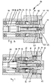
- Figure 1 shows a longitudinal section through a generally designated by the numeral 10 spindle device according to the invention.
- the spindle device 10 according to the invention is designed as a high-frequency spindle and is suitable for use for the highest speeds in numerous machine tools, in particular for milling or grinding machines.
- the spindle device 10 has a housing 12 in which a generally designated by the numeral 14 spindle is rotatably mounted.
- the spindle 14 has a first tool-side end 15 and a second end 17.
- a spindle shaft 16 is at the first end 15 by means of a bearing 22, and rotatably supported at the second end 17 by means of a second bearing 24.
- a tool clamping device 20 of basically known design is provided which can be actuated via a centrally arranged pull rod 18.
- the pull rod 18 is biased by a spring assembly 26 in a clamping position of the tool clamping device 20.
- a rotary feedthrough designated overall by the numeral 36 is installed in the housing 12 of the spindle 14.
- the rotary feedthrough 36 comprises an independent bearing 40 for a spindle section 39 with a central receptacle 38, in which the drawbar 18 is guided at its end remote from the tool clamping device 20.
- the rotary feedthrough 36 further has at its end remote from the tool clamping device 20 all connections for the supply and removal of coolant and optionally for other supply lines.
- the spindle device 10 has an external cooling for external cooling of the housing 12, wherein channels 32 and 34 for the supply and removal of coolant can be seen in FIG.
- the spindle device 10 is additionally provided with an internal cooling for the spindle 14, which has a plurality of closed cooling channels, through which coolant flows, which is supplied and / or removed via connections on the rotary leadthrough 36 in the axial direction.
- the spindle device 10 additionally has a possibility for a coolant supply via the rotary leadthrough 36 into a central axial channel 30 of the drawbar 18, so as to allow a coolant supply to the tool, if desired.
- the spindle device 10 according to the invention can also be configured without such an option, provided that no cooling of the tool via the spindle 14 is desired for the particular application.
- the motor 28 for driving the spindle shaft 16 has an integrated into the housing 12 stator 29, which is cooled via the cooling channels 32, 34 from the outside.
- the associated rotor 31 is located directly on the spindle shaft 16 and is cooled by the internal cooling of the spindle 14 from the inside.
- the rotary feedthrough 36 is formed as a part with a separate housing 42 which is detachably connected to the housing 12 of the spindle device 10, for example screwed.
- a bearing with a bearing pair 40, 40a is installed, by means of which the spindle portion 39 is rotatably mounted with the central receptacle 38 for the pull rod 18.
- the rotary feedthrough 36 is closed by a flange 41 to the outside, through which all connecting lines for the spindle are guided to the outside and optionally provided with suitable screw connections.
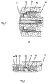
- two inflow openings 44, 45 can be seen, which are coupled to coolant lines.
- the inflow openings 44, 45 are each provided with a flow channel 48 or 49, is supplied via the coolant for internal cooling of the spindle 14, wherein this is respectively deflected at the first end 15 of the spindle 14 and is discharged back via the flange 41 of the rotary feedthrough 36 into connected coolant lines.
- the two inflow openings 44, 45 open into a common cavity 43. It would thus be possible to dispense with one of the two inflow openings 44, 45 and the coolant supply only via an inflow opening (and correspondingly the coolant discharge only via a drain opening). It is understood that the inflow and outflow openings can also be reversed.
- the flow channels 48, 49 are now coupled to one another via a series of channel sections, which extend through the spindle section 39, the pull rod 18 and the spindle shaft 16.
- the flow channels open into a deflecting element 80 (FIG. 6) and are returned from the latter via return channels, which in turn extend via channel sections in the spindle shaft 16, in the pull rod 18 and the spindle section 39 of the rotary leadthrough 36 ,
- return channels which in turn extend via channel sections in the spindle shaft 16, in the pull rod 18 and the spindle section 39 of the rotary leadthrough 36 .
- the flow channels 48, 49 initially extend from the common cavity 43 through a channel section 96 of the spindle section 39, from the end of which a passage into a channel section 88 of the pull rod 18 takes place (see FIG 6).
- the coolant passes axially or radially at the end of the spindle portion 39 into a channel portion 96.
- the cavity 43 and the rotating spindle portion 39 are now sealed against the housing 42 of the rotary feedthrough 36 initially by a first gap seal 50. Since this gap seal 50 operates without contact, leakage losses are to be expected in this case. Therefore, the gap seal 50 is followed by a contact seal 52 in the form of a lip seal.
- the contact seal 52 can be acted upon by compressed air via a pressure channel 70 such that the sealing lip is lifted off the sealing surface during operation of the spindle 14 under the influence of the supplied compressed air.
- the contact seal 52 is non-contact during operation of the spindle 14 and thus subject to no wear even at high speeds. Leakage losses exiting via the first gap seal 50 are thus removed by the countercurrent compressed air into a leakage return 72, which is connected to a leakage discharge opening 74.
- the pressure channel 70 is sealed off from the bearing 40 via a second gap seal 54.
- the compressed air is throttled over the second gap seal 54, but this could possibly leak into the bearing 40 and thus affect its lubrication in an undesirable manner.
- the air exiting via the second gap seal 54 is discharged via a bore 76 into a relief channel 77 and from there reaches an outlet 78 or a hose connected thereto (see FIG.
- any deterioration of the lubrication of the bearing 40 adjacent to the contact seal 52 is prevented by the application of a pressure medium or compressed air.
- coolant in the central axial channel 30 of the drawbar 18 can be supplied.
- the central axial channel 30 opens on the tool side and thus allows a supply of coolant to the tool or workpiece.
- FIG. 6 shows how the coolant in the inlet direction 79 is led from the end of the channel section 96 into channel sections 88 of the drawbar 18, which open into pockets 86 formed between the drawbar 18 and the spindle shaft 16. From these pockets 86 from the coolant passes Radial depressions 89 in corresponding axial passage portions of the spindle shaft 16, via which the coolant is guided into the region of the bearing 22.
- a deflection of the coolant via a deflecting element 80 in associated return channels.
- the deflecting element 80 is formed as a cylindrical sleeve and has recesses in its lateral surface, into each of which opens a pair of flow channels and return channels.
- the deflecting element 80 is inserted into a bore 81 of the spindle shaft 16 such that a closed overflow space 82 is formed with the depressions and the inner wall of the bore 81, by which the connection between the flow and return passages is established.
- the coolant is returned from the front pockets 84 via axial channel sections 92 in the drawbar 18 and finally passes through further pockets 93 and radial bores 94 in the spindle section 39 of the rotary union 36 and is then discharged via the channel sections 95.
- From Figure 6 is also the supply of the coolant from the channel portions 96 of the spindle portion 39 via holes in the channel sections 88 of the tie rod 18 and of there from over radial channel sections into the pockets 86 recognizable.
- the channel sections of the flow or return channels can basically be designed as bores.
- an embodiment with a shrunk-in tube is conceivable, in which the channel sections are milled.
- the carrier of the rotor 99 can be used to form the channel sections.
- the cooling system of the spindle device 10 allows targeted internal cooling of the spindle 14 over its entire area, wherein all the bearings 22, 24, 40 and the area of the rotor 31 are cooled sufficiently, so that maintained an operating temperature of about 30 ° during operation can be.
- a supply of coolant via the central axial channel 30 of the pull rod 18 is possible in order to cool an inserted tool or a workpiece.
- an external cooling is provided, can be cooled by the motor or spindle from the outside.
Landscapes
- Engineering & Computer Science (AREA)
- Mechanical Engineering (AREA)
- Physics & Mathematics (AREA)
- Fluid Mechanics (AREA)
- Auxiliary Devices For Machine Tools (AREA)
Abstract
Description
Die Erfindung betrifft eine Spindelvorrichtung mit einem Gehäuse, in dem eine rotierend antreibbare Spindel gelagert ist, die eine in einer Spindelwelle axial verschiebbare Zugstange zur Betätigung einer Werkzeugspanneinrichtung aufweist, wobei auf einer der Werkzeugspanneinrichtung abgewandten Seite der Spindel eine Drehdurchführung zur Zuführung eines Kühlmittels in die Spindel vorgesehen ist.The invention relates to a spindle device with a housing in which a rotatably driven spindle is mounted, which has an axially displaceable in a spindle shaft pull rod for actuating a tool clamping device, wherein on a side facing away from the tool clamping device of the spindle, a rotary feedthrough for supplying a coolant into the spindle is provided.
Eine derartige Spindelvorrichtung ist aus der
Bei der bekannten Spindelvorrichtung wird eine Zufuhr von Kühlmittel über die Zugstange zur Kühlung der Spindel genutzt. Das Kühlmittel wird seitlich aus der Spindel abgeführt. Dazu ist eine Zuführung von Druckluft an verschiedenen Stellen der Spindel notwendig, um die Lager frei von Kontaminationen zu halten und um ein Austreten von Kühlmittel zu unterbinden.In the known spindle device, a supply of coolant via the pull rod for cooling the spindle is used. The coolant is discharged laterally out of the spindle. For this purpose, a supply of compressed air at different points of the spindle is necessary to keep the bearings free of contamination and to prevent leakage of coolant.
Eine derartige Kühlung hat den Nachteil, dass diese nicht mit einer in vielen Fällen erforderlichen Kühlung des Werkzeugs kombiniert ist. Der Kühlmittelfluss über die Zugstange wird vielmehr ausschließlich zur Kühlung der Spindel selbst genutzt. Würde man dagegen die Kühlmittelzufuhr über den zentralen Kanal der Zugstange auch zur Kühlung des Werkzeugs nutzen, so wäre der Betrieb der Spindel grundsätzlich nur bei Kühlmittelzufuhr zum Werkzeug möglich, was teilweise jedoch unerwünscht ist.Such cooling has the disadvantage that it is not combined with a necessary cooling of the tool in many cases. The coolant flow via the pull rod is used exclusively for cooling the spindle itself. If, on the other hand, one would use the coolant supply via the central channel of the pull rod for cooling the tool, the operation of the spindle would basically only be possible with coolant supply to the tool, which is partly undesirable.
Des Weiteren ist die notwendige Druckluftzufuhr an verschiedenen Dichtungsstellen nachteilig und führt zu einem sehr komplizierten Aufbau der Spindel.Furthermore, the necessary compressed air supply to various sealing points is disadvantageous and leads to a very complicated construction of the spindle.
Aus der
Eine derartige Spindelausführung hat sich als anfällig gegenüber Vibrationen insbesondere bei hohen Drehzahlen erwiesen.Such a spindle design has proven to be susceptible to vibration, especially at high speeds.
Ferner erfordert es die verwendete Spaltdichtung mit Luft als abdichtendes Druckmedium, dass die Druckmittelversorgung ständig aufrecht erhalten wird, denn sonst kann Restkühlmittel ins Innere der Spindel gelangen, was diese beschädigen kann.Furthermore, it requires the gap seal used with air as a sealing pressure medium that the pressure medium supply is constantly maintained, otherwise residual refrigerant can get into the interior of the spindle, which can damage them.
Vor diesem Hintergrund liegt der Erfindung die Aufgabe zugrunde, eine verbesserte Spindelvorrichtung zu schaffen, die für hohe Spindeldrehzahlen geeignet ist. Dabei soll eine Kühlung der Spindel von innen unabhängig von einer möglichen Kühlmittelzufuhr zum Werkzeug ermöglicht sein. Ferner soll eine möglichst wirksame Kühlung der Spindel bei hoher Zuverlässigkeit im Dauerbetrieb gewährleistet sein.Against this background, the invention has for its object to provide an improved spindle device which is suitable for high spindle speeds. It should be possible to cool the spindle from the inside regardless of a possible coolant supply to the tool. Furthermore, the most effective cooling of the spindle should be ensured with high reliability in continuous operation.
Diese Aufgabe wird bei einer Spindelvorrichtung gemäß der eingangs genannten Art dadurch gelöst, dass eine Drehdurchführung vorgesehen ist, die einen drehbar gelagerten Spindelabschnitt aufweist, über den der mindestens eine Kühlkanal mit einer Zuflussöffnung und einer Abflussöffnung für das Kühlmedium gekoppelt ist.This object is achieved in a spindle device according to the aforementioned type in that a rotary feedthrough is provided which has a rotatably mounted spindle portion, via which the at least one cooling channel is coupled to an inflow opening and a discharge opening for the cooling medium.
Die Aufgabe der Erfindung wird auf diese Weise vollkommen gelöst.The object of the invention is completely solved in this way.
Erfindungsgemäß wird dadurch, dass die Spindel von mindestens einem geschlossenen Kühlkanal durchsetzt ist, der über die Drehdurchführung mit einer Zuflussöffnung und einer Abflussöffnung gekoppelt ist, eine Durchströmung der Spindel im Kreislauf ermöglicht, wobei die notwendigen Dichtungen alle in der Drehdurchführung angeordnet sein können. Dadurch ist ein einfacher und zuverlässiger Aufbau gewährleistet.According to the invention is characterized in that the spindle is penetrated by at least one closed cooling channel, which is coupled via the rotary feedthrough with an inlet opening and a drain opening, a flow through the spindle in the circuit allows, the necessary seals can all be arranged in the rotary feedthrough. This ensures a simple and reliable construction.
Da die Drehdurchführung einen eigenständig gelagerten Spindelabschnitt aufweist, über den die Kühlmittelzu- und Abfuhr erfolgt, lassen sich Vibrationen reduzieren und Leckagen minimieren.Since the rotary feedthrough has an independently mounted spindle section, via which the coolant supply and discharge takes place, vibrations can be reduced and leakages minimized.
Ferner kann die Spindelvorrichtung in einfacher Weise als komplettes Modul an einer Werkzeugmaschine montiert werden.Furthermore, the spindle device can be mounted in a simple manner as a complete module on a machine tool.
Zusätzlich erlaubt diese Anordnung eine unabhängige Versorgung eines von der Spindelvorrichtung angetriebenen Werkzeugs mit Kühlmittel, sofern dies gewünscht ist.In addition, this arrangement allows independent supply of a tool driven by the spindle device with coolant, if desired.
Die erfindungsgemäße Spindel zeichnet sich durch eine sehr gute Kühlwirkung bis in den vorderen, werkzeugseitigen Bereich einschließlich der vordersten Lagerstelle aus. Die Spindeltemperatur kann durchgehend auf maximal etwa 30 °C gehalten werden. Dagegen ist im Stand der Technik ohne eine Kühlung der Spindel von innen her mit Spindeltemperaturen von etwa 50 bis 70 °C im Betrieb zu rechnen.The spindle of the invention is characterized by a very good cooling effect into the front, tool-side area including the foremost bearing point. The spindle temperature can be maintained at a maximum of about 30 ° C throughout. In contrast, in the prior art without cooling the spindle from the inside with spindle temperatures of about 50 to 70 ° C expected during operation.
Weiterhin kann der Spindelstart erfindungsgemäß deutlich schneller als bei herkömmlichen Spindeln erfolgen. Schon nach etwa zwei Minuten stellen sich stationäre Verhältnisse an der Spindel ein, während hierzu im Stand der Technik ohne Spindelinnenkühlung in der Regel etwa 15 Minuten erforderlich sind. Die thermische Ausdehnung der Spindelwelle kann dadurch in minimalen Grenzen gehalten werden.Furthermore, the spindle start according to the invention can be done much faster than conventional spindles. After only about two minutes, stationary conditions arise at the spindle, whereas in the prior art without spindle internal cooling usually about 15 minutes are required. The thermal expansion of the spindle shaft can be kept within minimal limits.
Da die Lager nicht in den Kühlmittelfluss einbezogen sind, kann ein beliebiges Kühlmittel verwendet werden.Since the bearings are not included in the coolant flow, any coolant can be used.
Schließlich wird die Steifigkeit der Spindel im vorderen werkzeugseitigen Bereich nicht nachteilig beeinflusst, da hier keine Kühlmittelabfuhr aus der Spindel nach außen erfolgt.Finally, the rigidity of the spindle in the front area of the tool is not adversely affected since no coolant is discharged from the spindle to the outside.
Gemäß einer Weiterbildung der Erfindung ist der Spindelabschnitt mittels zweier Lager an einem Gehäuse der Drehdurchführung gelagert, das mit dem Gehäuse der Spindelvorrichtung lösbar verbunden ist, vorzugsweise damit verschraubt ist.According to one embodiment of the invention, the spindle portion is supported by means of two bearings on a housing of the rotary feedthrough, which is detachably connected to the housing of the spindle device, preferably screwed with it.
Auf diese Weise werden Vibrationen weiter reduziert und eine einfache Montage gewährleistet.In this way, vibrations are further reduced and ensures easy installation.
In bevorzugter Weiterbildung der Erfindung ist mindestens ein geschlossener Kühlkanal vorgesehen, der sich in Axialrichtung außermittig durch die Spindelwelle, die Zugstange und den Spindelabschnitt der Drehdurchführung erstreckt.In a preferred embodiment of the invention, at least one closed cooling channel is provided, which extends eccentrically in the axial direction through the spindle shaft, the pull rod and the spindle portion of the rotary feedthrough.
Diese Ausführung hat den Vorteil, dass auf diese Weise eine Kühlmittelzufuhr zu allen Lagerstellen der Spindel sowie zum Rotor des mit der Spindel kombinierten Antriebsmotors ermöglicht ist, während gleichzeitig zusätzlich eine Möglichkeit für eine Zufuhr von Kühlmittel über die Zugstange für eine unabhängige Kühlmittelzufuhr an das Werkzeug besteht.This embodiment has the advantage that in this way a coolant supply to all bearing points of the spindle and to the rotor of the drive motor combined with the spindle is made possible, while at the same time an additional possibility for a supply of coolant via the drawbar for an independent coolant supply to the tool.
Gemäß einer weiteren Ausführung der Erfindung weist jeder Kühlkanal einen mit der Zuflussöffnung gekoppelten Vorlaufkanal und einen mit der Abflussöffnung gekoppelten Rücklaufkanal auf, wobei Vorlaufkanal und Rücklaufkanal im Bereich eines ersten Endes der Spindel miteinander gekoppelt sind, vorzugsweise über ein Umlenkelement miteinander verbunden sind.According to a further embodiment of the invention, each cooling channel has a feed channel coupled to the feed opening and a return channel coupled to the discharge opening, wherein the feed channel and return channel are coupled to one another in the region of a first end of the spindle, preferably connected to one another via a deflection element.
Auf diese Weise kann eine besonders gleichmäßige Kühlung der Spindel über deren gesamte Länge gewährleistet werden. Auch lässt sich ein geschlossener Kühlkanal so auf einfache Weise realisieren.In this way, a particularly uniform cooling of the spindle over its entire length can be ensured. Also, a closed cooling channel can be realized in a simple manner.
In weiter bevorzugter Ausgestaltung der Erfindung ist der zumindest eine Kühlkanal gegen ein Gehäuse der Drehdurchführung über eine erste Spaltdichtung abgedichtet.In a further preferred embodiment of the invention, the at least one cooling channel is sealed against a housing of the rotary feedthrough via a first gap seal.
Eine Abdichtung über eine Spaltdichtung hat den Vorteil, dass diese verschleißfrei ist, so dass Nachteile bei hohen Spindeldrehzahlen vermieden werden.A seal over a gap seal has the advantage that it is wear-free, so that disadvantages at high spindle speeds can be avoided.
Gemäß einer weiteren Ausgestaltung der Erfindung ist der ersten Spaltdichtung eine Berührungsdichtung, vorzugsweise in Form einer Lippendichtung, nachgeordnet.According to a further embodiment of the invention, the first gap seal is arranged downstream of a contact seal, preferably in the form of a lip seal.
Durch die Berührungsdichtung können Leckagen, die über die Spaltdichtung noch erfolgen, abgefangen werden.Through the contact seal leaks that still occur via the gap seal, be intercepted.
In vorteilhafter Weiterbildung dieser Ausführung ist die Berührungsdichtung über einen Druckkanal derart mit einem Druckmedium, vorzugsweise mit Luft, beaufschlagbar, dass die Berührungsdichtung bei angetriebener Spindel berührungsfrei ist und durch das Druckmedium abgedichtet ist, während bei Stillstand der Spindel und abgeschaltetem Druckmedium eine Abdichtung über die Berührungsdichtung erfolgt.In an advantageous embodiment of this embodiment, the contact seal via a pressure channel so with a Pressure medium, preferably with air, acted upon, that the contact seal with driven spindle is non-contact and is sealed by the pressure medium, while at standstill of the spindle and switched-off pressure medium, a seal via the contact seal.
Diese Ausgestaltung hat den Vorteil, dass während des Betriebs der Spindel eine vollständig berührungslose Abdichtung gewährleistet ist, während bei Stillstand der Spindel und abgeschaltetem Druckmedium eine Abdichtung über die Berührungsdichtung erfolgt.This embodiment has the advantage that a completely non-contact seal is ensured during the operation of the spindle, while a seal on the contact seal takes place at standstill of the spindle and switched-off pressure medium.
Somit kann auch bei sehr hohen Spindeldrehzahlen eine vollständige und verschleißfreie Abdichtung gewährleistet werden, während bei Stillstand der Spindel die Abdichtung über die Berührungsdichtung gewährleistet ist.Thus, a complete and wear-free seal can be ensured even at very high spindle speeds, while the shaft is ensured by the contact seal at standstill of the spindle.
Gemäß einer weiteren Ausgestaltung der Erfindung ist der Druckkanal gegenüber einem Lager durch eine zweite Spaltdichtung abgedichtet.According to a further embodiment of the invention, the pressure channel is sealed against a bearing by a second gap seal.
Auf diese Weise wird sichergestellt, dass das Druckmedium aus dem Druckkanal, das zur berührungsfreien Abdichtung der Berührungsdichtung während des Betriebes genutzt wird, nicht in ein benachbartes Lager austritt und so dessen Schmierung beeinträchtigt.In this way it is ensured that the pressure medium from the pressure channel, which is used for non-contact sealing of the contact seal during operation, does not escape into an adjacent bearing and thus impairs its lubrication.
Der Druckkanal ist gemäß einer weiteren Ausführung der Erfindung mit einem Leckagerücklauf gekoppelt, über den aus der ersten Spaltdichtung austretende Leckagen des Kühlmittels abführbar sind.The pressure channel is coupled according to a further embodiment of the invention with a leakage return, can be discharged via the leaking from the first gap seal leaks of the coolant.
Auf diese Weise können Leckagen des Kühlmittels wirkungsvoll abgeführt werden.In this way, leaks of the coolant can be effectively dissipated.
In zusätzlicher Weiterbildung der Erfindung ist die zweite Spaltdichtung lagerseitig mit einem Entlastungskanal verbunden, über den über die zweite Spaltdichtung austretendes Druckmedium abführbar ist.In an additional development of the invention, the second gap seal is connected on the bearing side to a relief channel, via which pressure medium emerging via the second gap seal can be discharged.
Auf diese Weise wird ein an die zweite Spaltdichtung angrenzendes Lager vollständig gegen einen Zutritt des Druckmediums geschützt, da über die zweite Spaltdichtung gedrosseltes Druckmedium, das gegebenenfalls noch zu einer Beeinträchtigung des Lagers führen könnte, noch vor dem Lager über den Entlastungskanal abgeführt wird.In this way, an adjacent to the second gap seal bearing is completely protected against access of the pressure medium, as over the second gap seal throttled pressure medium, which could possibly still lead to a deterioration of the bearing is discharged before the camp via the discharge channel.
Gemäß einer weiteren Ausgestaltung der Erfindung weist die Drehdurchführung ein Gehäuse auf, das mit dem Gehäuse der Spindel verbunden ist und in dem eine zentrale Aufnahme zur Führung der Zugstange drehbar gelagert ist.According to a further embodiment of the invention, the rotary feedthrough on a housing which is connected to the housing of the spindle and in which a central receptacle for guiding the pull rod is rotatably mounted.
Auf diese Weise kann die Drehdurchführung als ein eigenständiges Modul aufgebaut sein, das mit dem Spindelgehäuse kombinierbar ist, wobei die Zugstange auf der Seite der Drehdurchführung in der zentralen Aufnahme geführt ist.In this way, the rotary feedthrough can be constructed as a separate module that can be combined with the spindle housing, wherein the pull rod is guided on the side of the rotary feedthrough in the central receptacle.
Gemäß einer Weiterbildung dieser Ausführung sind die Zuflussöffnung und die Abflussöffnung über Kanalabschnitte in der zentralen Aufnahme der Drehdurchführung mit Kanalabschnitten in der Zugstange gekoppelt, die mit weiteren Kanalabschnitten in der Spindelwelle gekoppelt sind.According to a development of this embodiment, the inflow opening and the outflow opening are coupled via channel sections in the central receptacle of the rotary feedthrough to channel sections in the drawbar which are coupled to further channel sections in the spindle shaft.
Auf diese Weise kann Kühlmittel über die Drehdurchführung gezielt über verschiedene Kühlkanäle zur Kühlung sämtlicher Lagerstellen und zur Kühlung des Rotors zugeführt werden, um eine besonders wirkungsvolle Kühlung der Spindel von innen her zu gewährleisten.In this way, coolant can be selectively supplied via the rotary feedthrough via different cooling channels for cooling all bearings and for cooling the rotor to ensure a particularly effective cooling of the spindle from the inside.
In vorteilhafter Weiterbildung der Erfindung erstreckt sich der zumindest eine Kühlkanal zumindest über den Bereich aller Lager der Spindeln und über den Bereich eines Rotors eines Antriebsmotors der Spindel.In an advantageous development of the invention, the at least one cooling channel extends at least over the area of all bearings of the spindles and over the area of a rotor of a drive motor of the spindle.
Auf diese Weise ist eine wirkungsvolle Kühlung der Spindel an den wesentlichen Teilen gewährleistet, die während des Betriebs der Spindel Wärme freisetzen.In this way, an effective cooling of the spindle is ensured at the essential parts that release heat during operation of the spindle.
Gemäß einer weiteren Ausgestaltung der Erfindung sind die Rücklaufkanäle und Vorlaufkanäle im Bereich des ersten Endes der Spindelwelle über ein Umlenkelement miteinander verbunden.According to a further embodiment of the invention, the return channels and flow channels are connected to each other in the region of the first end of the spindle shaft via a deflecting element.
Es versteht sich, dass die vorstehend genannten und die nachstehend noch zu erläuternden Merkmale der Erfindung nicht nur in der jeweils angegebenen Kombination, sondern auch in anderen Kombinationen oder in Alleinstellung verwendbar sind, ohne den Rahmen der Erfindung zu verlassen.It is understood that the features of the invention mentioned above and those yet to be explained below can be used not only in the particular combination indicated, but also in other combinations or in isolation, without departing from the scope of the invention.
Weitere Merkmale und Vorteile der Erfindung ergeben sich aus der nachfolgenden Beschreibung eines bevorzugten Ausführungsbeispiels unter Bezugnahme auf die Zeichnung.
- Figur 1
- zeigt einen Längsschnitt durch eine erfindungsgemäße Spindelvorrichtung.
- Figur 2
- zeigt einen vergrößerten Längsschnitt durch die Drehdurchführung der Spindelvorrichtung gemäß Figur 1 in einer Schnittebene, in der die Führung der Vorlaufkanäle erkennbar ist.
- Figur 3
- zeigt einen Schnitt durch die Drehdurchführung ähnlich gemäß Figur 2, wobei jedoch in der Schnittebene die Führung der Rücklaufkanäle erkennbar ist.
- Figur 4
- zeigt einen Teilschnitt durch die Drehdurchführung gemäß der Figuren 2 und 3, aus dem im Bereich einer Berührungsdichtung der Drehdurchführung ein Leckagerücklauf zur Abführung von Leckageverlusten erkennbar ist.
- Figur 5
- zeigt einen Teilschnitt durch die Drehdurchführung gemäß Figur 4, aus dem ein Entlastungskanal zur Abführung von Druckmedium von einem benachbarten Lager erkennbar ist.
- Figur 6
- zeigt einen Teilschnitt durch die Spindelvorrichtung gemäß Figur 1, aus dem die Führung von Kanalabschnitten im Bereich der Spindelwelle, derZugstange und des Spindelabschnittes der Drehdurchführung erkennbar ist.
- FIG. 1
- shows a longitudinal section through a spindle device according to the invention.
- FIG. 2
- shows an enlarged longitudinal section through the rotary feedthrough of the spindle device according to Figure 1 in a sectional plane in which the leadership of the flow channels can be seen.
- FIG. 3
- shows a section through the rotary feedthrough similar to Figure 2, but in the Cutting plane, the leadership of the return channels is recognizable.
- FIG. 4
- shows a partial section through the rotary feedthrough according to Figures 2 and 3, from which in the region of a contact seal of the rotary feedthrough a leakage return for the removal of leakage losses can be seen.
- FIG. 5
- shows a partial section through the rotary feedthrough according to Figure 4, from which a discharge channel for the discharge of pressure medium from an adjacent warehouse can be seen.
- FIG. 6
- shows a partial section through the spindle device according to Figure 1, from which the guidance of channel sections in the region of the spindle shaft, the pull rod and the spindle portion of the rotary feedthrough is recognizable.
Figur 1 zeigt einen Längsschnitt durch eine insgesamt mit der Ziffer 10 bezeichnete Spindelvorrichtung gemäß der Erfindung.Figure 1 shows a longitudinal section through a generally designated by the numeral 10 spindle device according to the invention.
Die erfindungsgemäße Spindelvorrichtung 10 ist als Hochfrequenzspindel ausgebildet und ist zum Einsatz für höchste Drehzahlen bei zahlreichen Werkzeugmaschinen, insbesondere für Fräs- bzw. Schleifmaschinen geeignet.The
Die Spindelvorrichtung 10 weist ein Gehäuse 12 auf, in dem eine insgesamt mit der Ziffer 14 bezeichnete Spindel drehbar gelagert ist. Die Spindel 14 weist ein erstes werkzeugseitiges Ende 15 und ein zweites Ende 17 auf. Eine Spindelwelle 16 ist am ersten Ende 15 mittels einer Lagerung 22, sowie am zweiten Ende 17 mittels einer zweiten Lagerung 24 drehbar gelagert. Am ersten Ende 15 der Spindel bzw. Spindelwelle 16 ist eine Werkzeugspanneinrichtung 20 grundsätzlich bekannter Bauart vorgesehen, die über eine zentral angeordnete Zugstange 18 betätigbar ist. Die Zugstange 18 ist durch ein Federpaket 26 in eine Spannstellung der Werkzeugspanneinrichtung 20 vorgespannt. Im Bereich des zweiten Endes 17 ist eine insgesamt mit der Ziffer 36 bezeichnete Drehdurchführung in das Gehäuse 12 der Spindel 14 eingebaut. Die Drehdurchführung 36 umfasst eine eigenständige Lagerung 40 für eine einen Spindelabschnitt 39 mit einer zentralen Aufnahme 38, in der die Zugstange 18 an ihrem der Werkzeugspanneinrichtung 20 abgewandten Ende geführt ist. Die Drehdurchführung 36 weist ferner an ihrem der Werkzeugspanneinrichtung 20 abgewandten Ende sämtliche Anschlüsse für die Zu- und Abfuhr von Kühlmittel und gegebenenfalls für weitere Versorgungsleitungen auf.The
Die Spindelvorrichtung 10 besitzt eine externe Kühlung für eine Außenkühlung des Gehäuses 12, wobei in Figur 1 Kanäle 32 und 34 für die Zufuhr- bzw. Abfuhr von Kühlmittel erkennbar sind.The
Erfindungsgemäß ist die Spindelvorrichtung 10 zusätzlich mit einer Innenkühlung für die Spindel 14 versehen, die eine Mehrzahl von geschlossenen Kühlkanälen aufweist, die von Kühlmittel durchströmt werden, das über Anschlüsse an der Drehdurchführung 36 in Axialrichtung zu- bzw. abgeführt wird.According to the invention, the
Des Weiteren besitzt die erfindungsgemäße Spindelvorrichtung 10 zusätzlich eine Möglichkeit für eine Kühlmittelzuführung über die Drehdurchführung 36 in einen zentralen Axialkanal 30 der Zugstange 18, um so eine Kühlmittelzufuhr zum Werkzeug zu ermöglichen, sofern dies gewünscht ist.Furthermore, the
Es versteht sich, dass die erfindungsgemäße Spindelvorrichtung 10 jedoch auch ohne eine solche Option ausgestaltet sein kann, sofern für den jeweiligen Anwendungsfall keine Kühlung des Werkzeugs über die Spindel 14 gewünscht ist.It goes without saying, however, that the
Der Motor 28 zum Antrieb der Spindelwelle 16 weist einen in das Gehäuse 12 integrierten Stator 29 auf, der über die Kühlkanäle 32, 34 von außen gekühlt wird. Der zugehörige Rotor 31 befindet sich unmittelbar auf der Spindelwelle 16 und wird durch die Innenkühlung der Spindel 14 von innen her gekühlt.The
Die Ausgestaltung der Drehdurchführung 36 und des Kühlsystems der Spindelvorrichtung 10 wird nunmehr anhand der Figuren 2 bis 6 näher erläutert.The design of the
Aus der vergrößerten Darstellung der Figuren 2 und 3 ist ersichtlich, dass die Drehdurchführung 36 als ein Teil mit einem eigenständigen Gehäuse 42 ausgebildet ist, das mit dem Gehäuse 12 der Spindelvorrichtung 10 lösbar verbunden ist, beispielsweise verschraubt ist.From the enlarged view of Figures 2 and 3 it can be seen that the
Im Gehäuse 42 der Drehdurchführung 36 ist eine Lagerung mit einem Lagerpaar 40, 40a eingebaut, mit Hilfe dessen der Spindelabschnitt 39 mit der zentralen Aufnahme 38 für die Zugstange 18 drehbar gelagert ist. An ihrem der Werkzeugspanneinrichtung 20 abgewandten Ende ist die Drehdurchführung 36 durch einen Flansch 41 nach außen abgeschlossen, durch den sämtliche Verbindungsleitungen für die Spindel nach außen geführt sind und gegebenenfalls mit geeigneten Schraubanschlüssen versehen sind.In the
In Figur 2 sind zwei Zuflussöffnungen 44, 45 erkennbar, die mit Kühlmittelleitungen gekoppelt sind. Die Zuflussöffnungen 44, 45 sind jeweils mit einem Vorlaufkanal 48 bzw. 49 verbunden, über den Kühlmittel zur Innenkühlung der Spindel 14 zugeführt wird, wobei dies am ersten Ende 15 der Spindel 14 jeweils umgelenkt wird und zurück über den Flansch 41 der Drehdurchführung 36 in angeschlossene Kühlmittelleitungen abgeführt wird. Die beiden Zuflussöffnungen 44, 45 münden in einen gemeinsamen Hohlraum 43. Es könnte somit auch auf eine der beiden Zuflussöffnungen 44, 45 verzichtet werden und die Kühlmittelversorgung lediglich über eine Zuflussöffnung erfolgen (und in entsprechender Weise die Kühlmittelabfuhr nur über eine Abflussöffnung). Es versteht sich, dass die Zu- und Abflussöffnungen auch vertauscht werden können.2, two
Die Vorlaufkanäle 48, 49 sind nun über eine Reihe von Kanalabschnitten, die sich durch den Spindelabschnitt 39, die Zugstange 18 und die Spindelwelle 16 erstrecken, miteinander gekoppelt. Am ersten Ende 15 der Spindelwelle 16 münden die Vorlaufkanäle in ein Umlenkelement 80 (Figur 6) und sind von diesem aus über Rücklaufkanäle, die sich wiederum über Kanalabschnitte in der Spindelwelle 16, in der Zugstange 18 und dem Spindelabschnitt 39 der Drehdurchführung 36 erstrecken, zurückgeführt. Es sind mehrere Vorlaufkanäle in gleichmäßigen Winkelabständen voneinander vorgesehen, die jeweils mit einem Rücklaufkanal gekoppelt sind.The
Aus der Darstellung gemäß Figur 2 ist erkennbar, dass sich die Vorlaufkanäle 48, 49 von dem gemeinsamen Hohlraum 43 aus zunächst durch einen Kanalabschnitt 96 des Spindelabschnittes 39 erstrecken, von dessen Ende aus ein Übertritt in einen Kanalabschnitt 88 der Zugstange 18 erfolgt (vgl. Figur 6).From the illustration according to FIG. 2, it can be seen that the
Von dem gemeinsamen Hohlraum 43 im Flansch 41 aus gelangt das Kühlmittel axial oder radial am Ende des Spindelabschnittes 39 in einen Kanalabschnitt 96. Der Hohlraum 43 und der sich drehende Spindelabschnitt 39 sind nun gegenüber dem Gehäuse 42 der Drehdurchführung 36 zunächst durch eine erste Spaltdichtung 50 abgedichtet. Da diese Spaltdichtung 50 berührungslos arbeitet, ist hierbei mit Leckageverlusten zu rechnen. Daher ist der Spaltdichtung 50 eine Berührungsdichtung 52 in Form einer Lippendichtung nachgeordnet.From the
Die Berührungsdichtung 52 ist gemäß Figur 4 über einen Druckkanal 70 derart mit Druckluft beaufschlagbar, dass die Dichtlippe während des Betriebs der Spindel 14 unter dem Einfluss der zugeführten Druckluft von der Dichtfläche abgehoben ist. So ist die Berührungsdichtung 52 während des Betriebs der Spindel 14 berührungslos und somit selbst bei hohen Drehzahlen keinem Verschleiß unterworfen. Über die erste Spaltdichtung 50 austretende Leckageverluste werden so durch die entgegenströmende Druckluft in einen Leckagerücklauf 72 abgeführt, der mit einer Leckageabflussöffnung 74 verbunden ist.According to FIG. 4, the
Damit die über den Druckkanal 70 zugeführte Druckluft nicht zu einer Beeinträchtigung des benachbarten Lagers 40 führt, ist der Druckkanal 70 über eine zweite Spaltdichtung 54 gegenüber dem Lager 40 abgedichtet. Die Druckluft wird über die zweite Spaltdichtung 54 gedrosselt, jedoch könnte diese ggf. noch in das Lager 40 austreten und somit dessen Schmierung in unerwünschter Weise beeinträchtigen.So that the compressed air supplied via the
Um dies zu verhindern, wird die über die zweite Spaltdichtung 54 austretende Luft über eine Bohrung 76 in einen Entlastungskanal 77 abgeführt und gelangt von dort aus an einen Ausgang 78 bzw. einen daran angeschlossenen Schlauch (vgl. Figur 5). So wird jede Beeinträchtigung der Schmierung des der Berührungsdichtung 52 benachbarten Lagers 40 durch die Beaufschlagung mit einem Druckmedium bzw. Druckluft verhindert.In order to prevent this, the air exiting via the
In Figur 3 ist nun die Führung des Rücklaufs im Bereich der Drehdurchführung 36 erkennbar. Die in Figur 3 dargestellten, insgesamt mit den Ziffern 66 und 67 bezeichneten Rücklaufkanäle münden über Abflussöffnungen 62, 63 im Flansch 41 in angeschlossene Kühlleitungen (nicht dargestellt), die zu einem Kühlmittelreservoir zurückführen. Die Rücklaufkanäle 66, 67 weisen im Bereich der zentralen Aufnahme 38 Kanalabschnitte 95 auf, in die das rückgeführte Kühlmittel über Bohrungen 94 aus der Zugstange 18 eingeführt wird. Das Kühlmittel fließt durch die Kanalabschnitte 95, wie durch die Pfeile 69 angedeutet, in Bohrungen im Mantel der zentralen Aufnahme 38 in Axialrichtung. Es wird schließlich durch radiale Durchtrittskanäle durch die erste Spaltdichtung 50 hindurch nach außen abgeführt und gelangt dann in die Abflussöffnungen 62 bzw. 63 im Flansch 41.In Figure 3, the leadership of the return is now recognizable in the region of the
Über einen Zuführschlauch, der über eine Verschraubung (nicht dargestellt) mit einer zentralen Zuflussöffnung 56 am Flansch 41 verbunden ist, kann zusätzlich Kühlmittel in den zentralen Axialkanal 30 der Zugstange 18 zugeführt werden. Der zentrale Axialkanal 30 mündet werkzeugseitig und erlaubt so eine Zufuhr von Kühlmittel zum Werkzeug bzw. Werkstück.Via a supply hose, which is connected via a screw (not shown) with a central inlet opening 56 on the
Die Kühlmittelführung durch die Vorlauf- bzw. Rücklaufkanäle von der zentralen Aufnahme 38 über die Zugstange 18 in die Spindelwelle 16 und zurück über die Spindelwelle 16 und die Zugstange 18 durch die zentrale Aufnahme 38 ist aus Figur 6 ersichtlich.The coolant guide through the flow or return channels from the
Figur 6 zeigt, wie das Kühlmittel in Zulaufrichtung 79 von dem Ende des Kanalabschnittes 96 in Kanalabschnitte 88 der Zugstange 18 geführt wird, die in Taschen 86 münden, die zwischen der Zugstange 18 und der Spindelwelle 16 gebildet sind. Von diesen Taschen 86 aus gelangt das Kühlmittel über radiale Vertiefungen 89 in entsprechende Axialkanalabschnitte der Spindelwelle 16, über die das Kühlmittel bis in den Bereich der Lagerung 22 geführt ist. Hier erfolgt eine Umlenkung des Kühlmittels über ein Umlenkelement 80 in zugeordnete Rücklaufkanäle. Das Umlenkelement 80 ist als eine zylindrische Hülse ausgebildet und weist in seiner Mantelfläche Vertiefungen auf, in die jeweils ein Paar von Vorlaufkanälen und Rücklaufkanälen ausmündet. Das Umlenkelement 80 ist so in eine Bohrung 81 der Spindelwelle 16 eingesetzt, dass mit den Vertiefungen und der Innenwand der Bohrung 81 jeweils ein abgeschlossener Überströmraum 82 gebildet wird, durch den die Verbindung zwischen den Vorlauf- und Rücklaufkanälen hergestellt wird.FIG. 6 shows how the coolant in the
Aus Figur 6 ist erkennbar, wie das Kühlmittel von dem Umlenkelement 80 aus über Kanalabschnitte 83 in der Spindelwelle 16 in Richtung der Pfeile 85 zurückgeführt wird und schließlich über eine Vertiefung 87 der Spindelwelle 16 in eine vordere Tasche 84 gelangt, die zwischen der Zugstange 18 und der Spindelwelle 16 gebildet ist. Während über diese vorderen Taschen 84 der Rückfluss über die Zugstange 18 erfolgt, erfolgt der Zufluss über die benachbarten hinteren Taschen 86.From Figure 6 it can be seen how the coolant from the deflecting
Das Kühlmittel wird von den vorderen Taschen 84 aus über axiale Kanalabschnitte 92 in der Zugstange 18 zurückgeführt und gelangt schließlich über weitere Taschen 93 und Radialbohrungen 94 in den Spindelabschnitt 39 der Drehdurchführung 36 und wird dann über die Kanalabschnitte 95 abgeführt.The coolant is returned from the
Aus Figur 6 ist ferner die Zuführung des Kühlmittels aus den Kanalabschnitten 96 des Spindelabschnittes 39 über Bohrungen in die Kanalabschnitte 88 der Zugstange 18 und von dort aus über radiale Kanalabschnitte bis in die Taschen 86 erkennbar.From Figure 6 is also the supply of the coolant from the
Die Kanalabschnitte der Vorlauf- bzw. Rücklaufkanäle können grundsätzlich als Bohrungen ausgeführt sein. Alternativ ist auch eine Ausführung mit einem eingeschrumpften Rohr denkbar, in das die Kanalabschnitte eingefräst sind. Ferner kann auch der Träger des Rotors 99 zur Ausbildung der Kanalabschnitte genutzt werden.The channel sections of the flow or return channels can basically be designed as bores. Alternatively, an embodiment with a shrunk-in tube is conceivable, in which the channel sections are milled. Furthermore, the carrier of the
Insgesamt ermöglicht das Kühlsystem der Spindelvorrichtung 10 eine gezielte Innenkühlung der Spindel 14 über deren gesamten Bereich, wobei sämtliche Lager 22, 24, 40 und der Bereich des Rotors 31 in ausreichender Weise gekühlt werden, so dass eine Betriebstemperatur von ca. 30° im Betrieb eingehalten werden kann.Overall, the cooling system of the
Zusätzlich ist eine Zufuhr von Kühlmittel über den zentralen Axialkanal 30 der Zugstange 18 möglich, um ein eingesetztes Werkzeug bzw. ein Werkstück kühlen zu können.In addition, a supply of coolant via the central
Schließlich ist eine externe Kühlung vorgesehen, durch die Motor bzw. Spindel von außen gekühlt werden können.Finally, an external cooling is provided, can be cooled by the motor or spindle from the outside.
Claims (14)
Applications Claiming Priority (1)
| Application Number | Priority Date | Filing Date | Title |
|---|---|---|---|
| DE102005030277A DE102005030277B4 (en) | 2005-06-21 | 2005-06-21 | Spindle device with internal cooling |
Publications (3)
| Publication Number | Publication Date |
|---|---|
| EP1736277A2 true EP1736277A2 (en) | 2006-12-27 |
| EP1736277A3 EP1736277A3 (en) | 2007-04-04 |
| EP1736277B1 EP1736277B1 (en) | 2008-07-02 |
Family
ID=36992779
Family Applications (1)
| Application Number | Title | Priority Date | Filing Date |
|---|---|---|---|
| EP06010514A Active EP1736277B1 (en) | 2005-06-21 | 2006-05-22 | Spindle device with through coolant and closed spindle cooling circuit running through a rotary coupling |
Country Status (2)
| Country | Link |
|---|---|
| EP (1) | EP1736277B1 (en) |
| DE (2) | DE102005030277B4 (en) |
Cited By (17)
| Publication number | Priority date | Publication date | Assignee | Title |
|---|---|---|---|---|
| WO2007144405A1 (en) | 2006-06-16 | 2007-12-21 | Mann+Hummel Gmbh | Compact filter element with knock protection |
| WO2008123407A1 (en) * | 2007-03-30 | 2008-10-16 | Thk Co., Ltd. | Rotation bearing, rotation table device, and method of dermining table diameter |
| EP2058085A1 (en) * | 2007-11-08 | 2009-05-13 | Step-Tec AG | Shaft cooling for a machine tool motor spindle |
| ITMI20081999A1 (en) * | 2008-11-11 | 2010-05-12 | Capellini S R L | TOOL UNLOCKING DEVICE WITH INTEGRATED COOLING, PARTICULARLY FOR SPINDLES. |
| CN102902287A (en) * | 2012-10-22 | 2013-01-30 | 北京工业大学 | Electric spindle active thermal balance temperature control device and temperature control method |
| CN104097100A (en) * | 2013-04-08 | 2014-10-15 | 贝特霍尔德·赫姆勒机器制造股份公司 | two-part tool spindle with liquid cooling portion |
| CN104174880A (en) * | 2014-08-27 | 2014-12-03 | 江苏星晨高速电机有限公司 | Non-contact hollow water draining device applied to horizontal type electric spindle and used for replacing rotary joint |
| CN104889425A (en) * | 2015-06-11 | 2015-09-09 | 浙江日发精密机械股份有限公司 | High speed spindle box structure |
| CN109550978A (en) * | 2019-02-15 | 2019-04-02 | 江苏凯勒姆智能装备有限公司 | A kind of spindle box of turn-milling cutting equipment |
| CN109590750A (en) * | 2019-02-15 | 2019-04-09 | 江苏凯勒姆智能装备有限公司 | A kind of turning-milling complex processing equipment |
| EP3495677A1 (en) | 2017-12-05 | 2019-06-12 | Fischer Engineering Solutions AG | Gas bearing cartridge and use of same |
| CN110560715A (en) * | 2019-09-27 | 2019-12-13 | 广州飞速尔精密部件有限公司 | Synchronous carving of axle in-core cooling permanent magnetism mills electric main shaft |
| CN110834102A (en) * | 2019-11-23 | 2020-02-25 | 深圳市爱贝科精密机械有限公司 | Synchronous cooling type electric spindle |
| CN111940766A (en) * | 2020-07-07 | 2020-11-17 | 广州市昊志机电股份有限公司 | Air-floatation motorized spindle and machine tool |
| CN112974867A (en) * | 2021-03-02 | 2021-06-18 | 广州市昊志机电股份有限公司 | Air floatation electric spindle and drilling machine |
| CN113427400A (en) * | 2021-07-08 | 2021-09-24 | 江苏工大金凯高端装备制造有限公司 | High-speed air-floatation grinding main shaft |
| CN115498818A (en) * | 2022-09-14 | 2022-12-20 | 无锡市荣华机械制造有限公司 | Constant-torque engraving and milling electric spindle |
Families Citing this family (10)
| Publication number | Priority date | Publication date | Assignee | Title |
|---|---|---|---|---|
| DE102008026924B4 (en) * | 2008-06-05 | 2010-03-04 | Fischer AG Präzisionsspindeln | Rotary feedthrough of a coolant supply |
| DE102008058941A1 (en) * | 2008-11-25 | 2010-05-27 | Franz Kessler Gmbh | Machine tool i.e. cutting machine such as grinding machine, for cutting workpiece, has cooling channel running through shaft and directing coolant through shaft, where channel is partially spaced from longitudinal axis than clamping element |
| DE102010045285A1 (en) * | 2010-09-14 | 2012-03-15 | Josef Reinauer | Machine tool spindle for driving tool system, has integrated pneumatic release unit clamping and unclamping two parts of tool system, and comprising pressure rod, pressure chamber, force transfer cylinder and pressure chamber module |
| CN102120266A (en) * | 2010-12-27 | 2011-07-13 | 东莞理工学院 | High-speed precise electric spindle cooling system |
| DE202012003528U1 (en) | 2012-04-05 | 2012-05-18 | Innovative Fertigungstechnologie Gmbh (Ift) | Device for compensating thermal deformations on a motor spindle |
| CN103737027A (en) * | 2013-12-31 | 2014-04-23 | 广州市昊志机电股份有限公司 | High-speed engraving and milling electric spindle |
| DE102016102035A1 (en) * | 2016-02-05 | 2017-08-10 | Röhm Gmbh | tool spindle |
| DE102016114036A1 (en) * | 2016-07-29 | 2018-02-01 | Ott-Jakob Spanntechnik Gmbh | Work spindle cooling device and machine tool processing unit with such a work spindle cooling device |
| DE102017121294B4 (en) * | 2017-09-14 | 2022-03-17 | Berg & Co. Gmbh | Spindle unit for machine tools |
| DE102020120038A1 (en) | 2020-07-29 | 2022-02-03 | Technische Hochschule Köln | Temperature control of a machine module |
Citations (7)
| Publication number | Priority date | Publication date | Assignee | Title |
|---|---|---|---|---|
| JPH0724687A (en) * | 1993-07-07 | 1995-01-27 | Makino Milling Mach Co Ltd | Main spindle device for machine tool |
| DE19516986A1 (en) * | 1995-05-09 | 1996-11-14 | Sauter Kg Feinmechanik | Spindle head for machine tool |
| JP2000158288A (en) * | 1998-11-27 | 2000-06-13 | Koyo Mach Ind Co Ltd | Main spindle cooling device for machine tool and spindle device |
| JP2000288870A (en) * | 1999-04-08 | 2000-10-17 | Makino Milling Mach Co Ltd | Rotating spindle device |
| EP1143159A1 (en) * | 1999-10-26 | 2001-10-10 | Makino Milling Machine Co. Ltd. | Rotating shaft device and machine tool having the rotating shaft device |
| US6398468B1 (en) * | 2001-01-19 | 2002-06-04 | Bayer Machine Tech Llc | Machine tool quill spindle |
| EP1163072B1 (en) * | 1999-03-23 | 2004-09-08 | Lind Finance & Development AB | Device of a tool spindle |
Family Cites Families (3)
| Publication number | Priority date | Publication date | Assignee | Title |
|---|---|---|---|---|
| DE8435005U1 (en) * | 1984-11-29 | 1986-04-03 | Werkzeugmaschinenfabrik Adolf Waldrich Coburg Gmbh & Co, 8630 Coburg | Machine tool with a machine tool spindle with cooling device in a headstock |
| JPH10230434A (en) * | 1997-02-21 | 1998-09-02 | Gat G Fuer Antriebstechnik Mbh | Method and device for supplying fluid mixture to rotating machine part |
| JP2000028870A (en) * | 1998-07-14 | 2000-01-28 | Hitachi Ltd | Optical coupler |
-
2005
- 2005-06-21 DE DE102005030277A patent/DE102005030277B4/en not_active Expired - Fee Related
-
2006
- 2006-05-22 EP EP06010514A patent/EP1736277B1/en active Active
- 2006-05-22 DE DE502006001013T patent/DE502006001013D1/en active Active
Patent Citations (7)
| Publication number | Priority date | Publication date | Assignee | Title |
|---|---|---|---|---|
| JPH0724687A (en) * | 1993-07-07 | 1995-01-27 | Makino Milling Mach Co Ltd | Main spindle device for machine tool |
| DE19516986A1 (en) * | 1995-05-09 | 1996-11-14 | Sauter Kg Feinmechanik | Spindle head for machine tool |
| JP2000158288A (en) * | 1998-11-27 | 2000-06-13 | Koyo Mach Ind Co Ltd | Main spindle cooling device for machine tool and spindle device |
| EP1163072B1 (en) * | 1999-03-23 | 2004-09-08 | Lind Finance & Development AB | Device of a tool spindle |
| JP2000288870A (en) * | 1999-04-08 | 2000-10-17 | Makino Milling Mach Co Ltd | Rotating spindle device |
| EP1143159A1 (en) * | 1999-10-26 | 2001-10-10 | Makino Milling Machine Co. Ltd. | Rotating shaft device and machine tool having the rotating shaft device |
| US6398468B1 (en) * | 2001-01-19 | 2002-06-04 | Bayer Machine Tech Llc | Machine tool quill spindle |
Non-Patent Citations (3)
| Title |
|---|
| PATENT ABSTRACTS OF JAPAN Bd. 1995, Nr. 04, 31. Mai 1995 (1995-05-31) & JP 07 024687 A (MAKINO MILLING MACH CO LTD), 27. Januar 1995 (1995-01-27) * |
| PATENT ABSTRACTS OF JAPAN Bd. 2000, Nr. 09, 13. Oktober 2000 (2000-10-13) & JP 2000 158288 A (KOYO MACH IND CO LTD), 13. Juni 2000 (2000-06-13) * |
| PATENT ABSTRACTS OF JAPAN Bd. 2000, Nr. 13, 5. Februar 2001 (2001-02-05) & JP 2000 288870 A (MAKINO MILLING MACH CO LTD), 17. Oktober 2000 (2000-10-17) * |
Cited By (31)
| Publication number | Priority date | Publication date | Assignee | Title |
|---|---|---|---|---|
| WO2007144405A1 (en) | 2006-06-16 | 2007-12-21 | Mann+Hummel Gmbh | Compact filter element with knock protection |
| WO2008123407A1 (en) * | 2007-03-30 | 2008-10-16 | Thk Co., Ltd. | Rotation bearing, rotation table device, and method of dermining table diameter |
| US8316776B2 (en) | 2007-03-30 | 2012-11-27 | Thk Co., Ltd. | Rotary bearing, rotary table device and table diameter determining method |
| CN101680488B (en) * | 2007-03-30 | 2014-01-01 | Thk株式会社 | Rotation bearing, rotation table device, and method of dermining table diameter |
| CN101855043B (en) * | 2007-11-08 | 2014-05-14 | 斯特普-特克股份公司 | Shaft cooler for tool motor spindle |
| EP2058085A1 (en) * | 2007-11-08 | 2009-05-13 | Step-Tec AG | Shaft cooling for a machine tool motor spindle |
| WO2009059954A1 (en) * | 2007-11-08 | 2009-05-14 | Step-Tec Ag | Shaft cooler for a tool motor spindle |
| CN101855043A (en) * | 2007-11-08 | 2010-10-06 | 斯特普-特克股份公司 | Shaft cooler for a tool motor spindle |
| US8684643B2 (en) | 2007-11-08 | 2014-04-01 | Step-Tec Ag | Shaft cooler for a tool motor spindle |
| ITMI20081999A1 (en) * | 2008-11-11 | 2010-05-12 | Capellini S R L | TOOL UNLOCKING DEVICE WITH INTEGRATED COOLING, PARTICULARLY FOR SPINDLES. |
| CN102902287B (en) * | 2012-10-22 | 2015-08-05 | 北京工业大学 | A kind of electric spindle active thermal balance Temp. control method |
| CN102902287A (en) * | 2012-10-22 | 2013-01-30 | 北京工业大学 | Electric spindle active thermal balance temperature control device and temperature control method |
| EP2789423A1 (en) * | 2013-04-08 | 2014-10-15 | Maschinenfabrik Berthold Hermle AG | Tool spindle divided in two with liquid cooling |
| CN104097100B (en) * | 2013-04-08 | 2018-04-13 | 贝特霍尔德·赫姆勒机器制造股份公司 | A kind of tool spindle of the driver under stress of two-piece type |
| CN104097100A (en) * | 2013-04-08 | 2014-10-15 | 贝特霍尔德·赫姆勒机器制造股份公司 | two-part tool spindle with liquid cooling portion |
| CN104174880A (en) * | 2014-08-27 | 2014-12-03 | 江苏星晨高速电机有限公司 | Non-contact hollow water draining device applied to horizontal type electric spindle and used for replacing rotary joint |
| CN104889425A (en) * | 2015-06-11 | 2015-09-09 | 浙江日发精密机械股份有限公司 | High speed spindle box structure |
| EP3495677A1 (en) | 2017-12-05 | 2019-06-12 | Fischer Engineering Solutions AG | Gas bearing cartridge and use of same |
| CN109550978B (en) * | 2019-02-15 | 2024-04-26 | 常州柯勒玛智能装备有限公司 | Spindle box of turning and milling equipment |
| CN109550978A (en) * | 2019-02-15 | 2019-04-02 | 江苏凯勒姆智能装备有限公司 | A kind of spindle box of turn-milling cutting equipment |
| CN109590750A (en) * | 2019-02-15 | 2019-04-09 | 江苏凯勒姆智能装备有限公司 | A kind of turning-milling complex processing equipment |
| CN109590750B (en) * | 2019-02-15 | 2024-05-31 | 常州柯勒玛智能装备有限公司 | Turning and milling combined machining equipment |
| CN110560715A (en) * | 2019-09-27 | 2019-12-13 | 广州飞速尔精密部件有限公司 | Synchronous carving of axle in-core cooling permanent magnetism mills electric main shaft |
| CN110834102A (en) * | 2019-11-23 | 2020-02-25 | 深圳市爱贝科精密机械有限公司 | Synchronous cooling type electric spindle |
| CN111940766B (en) * | 2020-07-07 | 2022-09-02 | 广州市昊志机电股份有限公司 | Air-floatation motorized spindle and machine tool |
| CN111940766A (en) * | 2020-07-07 | 2020-11-17 | 广州市昊志机电股份有限公司 | Air-floatation motorized spindle and machine tool |
| CN112974867A (en) * | 2021-03-02 | 2021-06-18 | 广州市昊志机电股份有限公司 | Air floatation electric spindle and drilling machine |
| CN113427400A (en) * | 2021-07-08 | 2021-09-24 | 江苏工大金凯高端装备制造有限公司 | High-speed air-floatation grinding main shaft |
| CN113427400B (en) * | 2021-07-08 | 2023-08-15 | 江苏工大金凯高端装备制造有限公司 | High-speed air-float grinding main shaft |
| CN115498818A (en) * | 2022-09-14 | 2022-12-20 | 无锡市荣华机械制造有限公司 | Constant-torque engraving and milling electric spindle |
| CN115498818B (en) * | 2022-09-14 | 2024-02-20 | 无锡市荣华机械制造有限公司 | Constant torque engraving and milling electric spindle |
Also Published As
| Publication number | Publication date |
|---|---|
| DE102005030277A1 (en) | 2007-01-04 |
| DE102005030277B4 (en) | 2007-10-31 |
| DE502006001013D1 (en) | 2008-08-14 |
| EP1736277B1 (en) | 2008-07-02 |
| EP1736277A3 (en) | 2007-04-04 |
Similar Documents
| Publication | Publication Date | Title |
|---|---|---|
| EP1736277B1 (en) | Spindle device with through coolant and closed spindle cooling circuit running through a rotary coupling | |
| EP2058085B1 (en) | Shaft cooling for a machine tool motor spindle | |
| DE102010037822B4 (en) | Tool holder for use in a machine tool and method for operating such a tool holder | |
| EP2665582B1 (en) | Tool revolver for machining workpieces and a machining system comprising such a tool revolver | |
| WO1997045667A1 (en) | Rotary transmission leadthrough for high pressures and high relative speeds | |
| EP0865837B1 (en) | Rolling mill drive with spindles having a toothed joint and with a device for circular lubrication | |
| DE10027750C5 (en) | Motor spindle for a machine tool and modular unit for such | |
| EP3503356B1 (en) | Coolant distributor for a machine assembly and corresponding machine assembly | |
| EP2433741B1 (en) | Machine tool with exchangeable spindle unit | |
| EP0440096B1 (en) | Spindle arrangement for workpieces for a lathe | |
| DE102019005057B4 (en) | spindle device | |
| DE102008064410A1 (en) | processing machine | |
| DE60013569T2 (en) | DEVICE FOR A TOOL SPINDLE | |
| EP2193907A1 (en) | Screw-type machine with axial compensation for thermal expansion | |
| EP1666671A1 (en) | Milling device for trench walls | |
| DE102019007416A1 (en) | Spindle device | |
| DE60013572T2 (en) | DEVICE FOR A TOOL SPINDLE | |
| WO2006102782A1 (en) | Transmission or motor spindle device comprising a sealing device for a machine tool, and use of said sealing device | |
| DE2911000C2 (en) | Rotary feedthrough for introducing flowable media into a rotating machine part | |
| DE60008990T2 (en) | Electric high-speed spindle with hybrid rotor bearing in woodworking machines | |
| DE10135419A1 (en) | Work machine for manufacturing has a work head with a housing which is positioned near a tool spindle in an axial cooling channel | |
| DE60013571T2 (en) | DEVICE FOR A TOOL SPINDLE | |
| DE102006007693A1 (en) | Rotary grinding of internal bores of components used tool having fluid cooled grinding discs | |
| EP1245329A1 (en) | Device for the supply of coolant/lubricant to a rotating tool with internal coolant passage | |
| DE60013568T2 (en) | DEVICE FOR A TOOL SPINDLE |
Legal Events
| Date | Code | Title | Description |
|---|---|---|---|
| PUAI | Public reference made under article 153(3) epc to a published international application that has entered the european phase |
Free format text: ORIGINAL CODE: 0009012 |
|
| AK | Designated contracting states |
Kind code of ref document: A2 Designated state(s): AT BE BG CH CY CZ DE DK EE ES FI FR GB GR HU IE IS IT LI LT LU LV MC NL PL PT RO SE SI SK TR |
|
| AX | Request for extension of the european patent |
Extension state: AL BA HR MK YU |
|
| PUAL | Search report despatched |
Free format text: ORIGINAL CODE: 0009013 |
|
| AK | Designated contracting states |
Kind code of ref document: A3 Designated state(s): AT BE BG CH CY CZ DE DK EE ES FI FR GB GR HU IE IS IT LI LT LU LV MC NL PL PT RO SE SI SK TR |
|
| AX | Request for extension of the european patent |
Extension state: AL BA HR MK YU |
|
| 17P | Request for examination filed |
Effective date: 20070530 |
|
| AKX | Designation fees paid |
Designated state(s): CH DE IT LI |
|
| GRAP | Despatch of communication of intention to grant a patent |
Free format text: ORIGINAL CODE: EPIDOSNIGR1 |
|
| GRAS | Grant fee paid |
Free format text: ORIGINAL CODE: EPIDOSNIGR3 |
|
| GRAA | (expected) grant |
Free format text: ORIGINAL CODE: 0009210 |
|
| AK | Designated contracting states |
Kind code of ref document: B1 Designated state(s): CH DE IT LI |
|
| REG | Reference to a national code |
Ref country code: CH Ref legal event code: EP |
|
| REF | Corresponds to: |
Ref document number: 502006001013 Country of ref document: DE Date of ref document: 20080814 Kind code of ref document: P |
|
| REG | Reference to a national code |
Ref country code: CH Ref legal event code: NV Representative=s name: BRAUNPAT BRAUN EDER AG |
|
| PLBE | No opposition filed within time limit |
Free format text: ORIGINAL CODE: 0009261 |
|
| STAA | Information on the status of an ep patent application or granted ep patent |
Free format text: STATUS: NO OPPOSITION FILED WITHIN TIME LIMIT |
|
| 26N | No opposition filed |
Effective date: 20090403 |
|
| REG | Reference to a national code |
Ref country code: CH Ref legal event code: NV Representative=s name: HEPP WENGER RYFFEL AG |
|
| REG | Reference to a national code |
Ref country code: DE Ref legal event code: R082 Ref document number: 502006001013 Country of ref document: DE Representative=s name: GLAWE DELFS MOLL PARTNERSCHAFT MBB VON PATENT-, DE |
|
| REG | Reference to a national code |
Ref country code: DE Ref legal event code: R082 Ref document number: 502006001013 Country of ref document: DE Representative=s name: GLAWE DELFS MOLL PARTNERSCHAFT MBB VON PATENT-, DE Ref country code: DE Ref legal event code: R082 Ref document number: 502006001013 Country of ref document: DE |
|
| REG | Reference to a national code |
Ref country code: DE Ref legal event code: R082 Ref document number: 502006001013 Country of ref document: DE Representative=s name: GLAWE DELFS MOLL PARTNERSCHAFT MBB VON PATENT-, DE |
|
| PGFP | Annual fee paid to national office [announced via postgrant information from national office to epo] |
Ref country code: CH Payment date: 20230724 Year of fee payment: 18 |
|
| PGFP | Annual fee paid to national office [announced via postgrant information from national office to epo] |
Ref country code: DE Payment date: 20240423 Year of fee payment: 19 |
|
| PGFP | Annual fee paid to national office [announced via postgrant information from national office to epo] |
Ref country code: IT Payment date: 20240426 Year of fee payment: 19 |