EP1736222A1 - Honeycomb structure - Google Patents
Honeycomb structure Download PDFInfo
- Publication number
- EP1736222A1 EP1736222A1 EP06001894A EP06001894A EP1736222A1 EP 1736222 A1 EP1736222 A1 EP 1736222A1 EP 06001894 A EP06001894 A EP 06001894A EP 06001894 A EP06001894 A EP 06001894A EP 1736222 A1 EP1736222 A1 EP 1736222A1
- Authority
- EP
- European Patent Office
- Prior art keywords
- honeycomb structure
- honeycomb
- alumina
- units
- silica
- Prior art date
- Legal status (The legal status is an assumption and is not a legal conclusion. Google has not performed a legal analysis and makes no representation as to the accuracy of the status listed.)
- Withdrawn
Links
- 239000002245 particle Substances 0.000 claims abstract description 62
- 239000012784 inorganic fiber Substances 0.000 claims abstract description 41
- 239000000919 ceramic Substances 0.000 claims abstract description 40
- 239000003566 sealing material Substances 0.000 claims abstract description 37
- 230000003746 surface roughness Effects 0.000 claims abstract description 24
- 238000005192 partition Methods 0.000 claims abstract description 7
- PNEYBMLMFCGWSK-UHFFFAOYSA-N aluminium oxide Inorganic materials [O-2].[O-2].[O-2].[Al+3].[Al+3] PNEYBMLMFCGWSK-UHFFFAOYSA-N 0.000 claims description 89
- VYPSYNLAJGMNEJ-UHFFFAOYSA-N Silicium dioxide Chemical compound O=[Si]=O VYPSYNLAJGMNEJ-UHFFFAOYSA-N 0.000 claims description 80
- 239000003054 catalyst Substances 0.000 claims description 73
- 239000000463 material Substances 0.000 claims description 48
- 239000011230 binding agent Substances 0.000 claims description 42
- 239000000377 silicon dioxide Substances 0.000 claims description 39
- 239000011248 coating agent Substances 0.000 claims description 30
- 238000000576 coating method Methods 0.000 claims description 30
- 239000000203 mixture Substances 0.000 claims description 20
- MCMNRKCIXSYSNV-UHFFFAOYSA-N Zirconium dioxide Chemical compound O=[Zr]=O MCMNRKCIXSYSNV-UHFFFAOYSA-N 0.000 claims description 12
- RMAQACBXLXPBSY-UHFFFAOYSA-N silicic acid Chemical compound O[Si](O)(O)O RMAQACBXLXPBSY-UHFFFAOYSA-N 0.000 claims description 9
- 239000010936 titanium Substances 0.000 claims description 8
- 239000004113 Sepiolite Substances 0.000 claims description 6
- RTAQQCXQSZGOHL-UHFFFAOYSA-N Titanium Chemical compound [Ti] RTAQQCXQSZGOHL-UHFFFAOYSA-N 0.000 claims description 6
- 229960000892 attapulgite Drugs 0.000 claims description 6
- 229910052625 palygorskite Inorganic materials 0.000 claims description 6
- 229910052624 sepiolite Inorganic materials 0.000 claims description 6
- 235000019355 sepiolite Nutrition 0.000 claims description 6
- 229910052719 titanium Inorganic materials 0.000 claims description 6
- 229910052784 alkaline earth metal Inorganic materials 0.000 claims description 5
- 229910052783 alkali metal Inorganic materials 0.000 claims description 4
- 150000001340 alkali metals Chemical class 0.000 claims description 4
- 229910000510 noble metal Inorganic materials 0.000 claims description 4
- HBMJWWWQQXIZIP-UHFFFAOYSA-N silicon carbide Chemical compound [Si+]#[C-] HBMJWWWQQXIZIP-UHFFFAOYSA-N 0.000 claims description 4
- 229910010271 silicon carbide Inorganic materials 0.000 claims description 4
- 229910052684 Cerium Inorganic materials 0.000 claims description 3
- 229910021536 Zeolite Inorganic materials 0.000 claims description 3
- OJMOMXZKOWKUTA-UHFFFAOYSA-N aluminum;borate Chemical compound [Al+3].[O-]B([O-])[O-] OJMOMXZKOWKUTA-UHFFFAOYSA-N 0.000 claims description 3
- GWXLDORMOJMVQZ-UHFFFAOYSA-N cerium Chemical compound [Ce] GWXLDORMOJMVQZ-UHFFFAOYSA-N 0.000 claims description 3
- HNPSIPDUKPIQMN-UHFFFAOYSA-N dioxosilane;oxo(oxoalumanyloxy)alumane Chemical compound O=[Si]=O.O=[Al]O[Al]=O HNPSIPDUKPIQMN-UHFFFAOYSA-N 0.000 claims description 3
- KZHJGOXRZJKJNY-UHFFFAOYSA-N dioxosilane;oxo(oxoalumanyloxy)alumane Chemical compound O=[Si]=O.O=[Si]=O.O=[Al]O[Al]=O.O=[Al]O[Al]=O.O=[Al]O[Al]=O KZHJGOXRZJKJNY-UHFFFAOYSA-N 0.000 claims description 3
- NJLLQSBAHIKGKF-UHFFFAOYSA-N dipotassium dioxido(oxo)titanium Chemical compound [K+].[K+].[O-][Ti]([O-])=O NJLLQSBAHIKGKF-UHFFFAOYSA-N 0.000 claims description 3
- 239000011521 glass Substances 0.000 claims description 3
- 229910052863 mullite Inorganic materials 0.000 claims description 3
- NTHWMYGWWRZVTN-UHFFFAOYSA-N sodium silicate Chemical compound [Na+].[Na+].[O-][Si]([O-])=O NTHWMYGWWRZVTN-UHFFFAOYSA-N 0.000 claims description 3
- 239000010457 zeolite Substances 0.000 claims description 3
- 230000000052 comparative effect Effects 0.000 description 49
- GWEVSGVZZGPLCZ-UHFFFAOYSA-N Titan oxide Chemical compound O=[Ti]=O GWEVSGVZZGPLCZ-UHFFFAOYSA-N 0.000 description 32
- 239000000835 fiber Substances 0.000 description 30
- 230000035939 shock Effects 0.000 description 24
- 239000007789 gas Substances 0.000 description 21
- 238000012360 testing method Methods 0.000 description 21
- 230000007423 decrease Effects 0.000 description 19
- 238000010304 firing Methods 0.000 description 17
- 238000000465 moulding Methods 0.000 description 16
- QCWXUUIWCKQGHC-UHFFFAOYSA-N Zirconium Chemical compound [Zr] QCWXUUIWCKQGHC-UHFFFAOYSA-N 0.000 description 14
- BASFCYQUMIYNBI-UHFFFAOYSA-N platinum Chemical compound [Pt] BASFCYQUMIYNBI-UHFFFAOYSA-N 0.000 description 14
- 229910052726 zirconium Inorganic materials 0.000 description 14
- 238000007789 sealing Methods 0.000 description 13
- 239000013585 weight reducing agent Substances 0.000 description 13
- 238000005259 measurement Methods 0.000 description 12
- 229910052751 metal Inorganic materials 0.000 description 12
- 239000002184 metal Substances 0.000 description 12
- 230000003252 repetitive effect Effects 0.000 description 8
- 238000001125 extrusion Methods 0.000 description 7
- 229910052697 platinum Inorganic materials 0.000 description 7
- 239000002994 raw material Substances 0.000 description 7
- 230000008646 thermal stress Effects 0.000 description 6
- 238000009924 canning Methods 0.000 description 5
- 238000006243 chemical reaction Methods 0.000 description 5
- 239000003795 chemical substances by application Substances 0.000 description 5
- 239000004927 clay Substances 0.000 description 5
- 229910052878 cordierite Inorganic materials 0.000 description 5
- 238000005238 degreasing Methods 0.000 description 5
- JSKIRARMQDRGJZ-UHFFFAOYSA-N dimagnesium dioxido-bis[(1-oxido-3-oxo-2,4,6,8,9-pentaoxa-1,3-disila-5,7-dialuminabicyclo[3.3.1]nonan-7-yl)oxy]silane Chemical compound [Mg++].[Mg++].[O-][Si]([O-])(O[Al]1O[Al]2O[Si](=O)O[Si]([O-])(O1)O2)O[Al]1O[Al]2O[Si](=O)O[Si]([O-])(O1)O2 JSKIRARMQDRGJZ-UHFFFAOYSA-N 0.000 description 5
- 238000011156 evaluation Methods 0.000 description 5
- 238000000034 method Methods 0.000 description 5
- 238000005498 polishing Methods 0.000 description 5
- 239000007787 solid Substances 0.000 description 5
- 239000002585 base Substances 0.000 description 4
- 238000009826 distribution Methods 0.000 description 4
- 239000011236 particulate material Substances 0.000 description 4
- 239000000843 powder Substances 0.000 description 4
- 238000004626 scanning electron microscopy Methods 0.000 description 4
- XLYOFNOQVPJJNP-UHFFFAOYSA-N water Substances O XLYOFNOQVPJJNP-UHFFFAOYSA-N 0.000 description 4
- UHOVQNZJYSORNB-UHFFFAOYSA-N Benzene Chemical compound C1=CC=CC=C1 UHOVQNZJYSORNB-UHFFFAOYSA-N 0.000 description 3
- 229920002134 Carboxymethyl cellulose Polymers 0.000 description 3
- LYCAIKOWRPUZTN-UHFFFAOYSA-N Ethylene glycol Chemical compound OCCO LYCAIKOWRPUZTN-UHFFFAOYSA-N 0.000 description 3
- OKKJLVBELUTLKV-UHFFFAOYSA-N Methanol Chemical compound OC OKKJLVBELUTLKV-UHFFFAOYSA-N 0.000 description 3
- 238000001354 calcination Methods 0.000 description 3
- 239000001768 carboxy methyl cellulose Substances 0.000 description 3
- 235000010948 carboxy methyl cellulose Nutrition 0.000 description 3
- 239000008112 carboxymethyl-cellulose Substances 0.000 description 3
- 230000008859 change Effects 0.000 description 3
- 238000005520 cutting process Methods 0.000 description 3
- 239000000314 lubricant Substances 0.000 description 3
- 239000002075 main ingredient Substances 0.000 description 3
- 229920000609 methyl cellulose Polymers 0.000 description 3
- 239000001923 methylcellulose Substances 0.000 description 3
- 235000010981 methylcellulose Nutrition 0.000 description 3
- 238000002156 mixing Methods 0.000 description 3
- 238000012986 modification Methods 0.000 description 3
- 230000004048 modification Effects 0.000 description 3
- 239000004014 plasticizer Substances 0.000 description 3
- KDLHZDBZIXYQEI-UHFFFAOYSA-N Palladium Chemical compound [Pd] KDLHZDBZIXYQEI-UHFFFAOYSA-N 0.000 description 2
- 230000002745 absorbent Effects 0.000 description 2
- 239000002250 absorbent Substances 0.000 description 2
- 230000032683 aging Effects 0.000 description 2
- 229910052788 barium Inorganic materials 0.000 description 2
- DSAJWYNOEDNPEQ-UHFFFAOYSA-N barium atom Chemical compound [Ba] DSAJWYNOEDNPEQ-UHFFFAOYSA-N 0.000 description 2
- 238000002485 combustion reaction Methods 0.000 description 2
- NLYAJNPCOHFWQQ-UHFFFAOYSA-N kaolin Chemical compound O.O.O=[Al]O[Si](=O)O[Si](=O)O[Al]=O NLYAJNPCOHFWQQ-UHFFFAOYSA-N 0.000 description 2
- 238000004898 kneading Methods 0.000 description 2
- 239000007788 liquid Substances 0.000 description 2
- 150000002739 metals Chemical class 0.000 description 2
- 239000011368 organic material Substances 0.000 description 2
- 238000005488 sandblasting Methods 0.000 description 2
- 229910001220 stainless steel Inorganic materials 0.000 description 2
- 239000010935 stainless steel Substances 0.000 description 2
- 238000003860 storage Methods 0.000 description 2
- LNAZSHAWQACDHT-XIYTZBAFSA-N (2r,3r,4s,5r,6s)-4,5-dimethoxy-2-(methoxymethyl)-3-[(2s,3r,4s,5r,6r)-3,4,5-trimethoxy-6-(methoxymethyl)oxan-2-yl]oxy-6-[(2r,3r,4s,5r,6r)-4,5,6-trimethoxy-2-(methoxymethyl)oxan-3-yl]oxyoxane Chemical compound CO[C@@H]1[C@@H](OC)[C@H](OC)[C@@H](COC)O[C@H]1O[C@H]1[C@H](OC)[C@@H](OC)[C@H](O[C@H]2[C@@H]([C@@H](OC)[C@H](OC)O[C@@H]2COC)OC)O[C@@H]1COC LNAZSHAWQACDHT-XIYTZBAFSA-N 0.000 description 1
- KXGFMDJXCMQABM-UHFFFAOYSA-N 2-methoxy-6-methylphenol Chemical compound [CH]OC1=CC=CC([CH])=C1O KXGFMDJXCMQABM-UHFFFAOYSA-N 0.000 description 1
- 239000005995 Aluminium silicate Substances 0.000 description 1
- 239000004375 Dextrin Substances 0.000 description 1
- 229920001353 Dextrin Polymers 0.000 description 1
- LFQSCWFLJHTTHZ-UHFFFAOYSA-N Ethanol Chemical compound CCO LFQSCWFLJHTTHZ-UHFFFAOYSA-N 0.000 description 1
- 239000001856 Ethyl cellulose Substances 0.000 description 1
- ZZSNKZQZMQGXPY-UHFFFAOYSA-N Ethyl cellulose Chemical compound CCOCC1OC(OC)C(OCC)C(OCC)C1OC1C(O)C(O)C(OC)C(CO)O1 ZZSNKZQZMQGXPY-UHFFFAOYSA-N 0.000 description 1
- 229920000663 Hydroxyethyl cellulose Polymers 0.000 description 1
- 239000004354 Hydroxyethyl cellulose Substances 0.000 description 1
- DGAQECJNVWCQMB-PUAWFVPOSA-M Ilexoside XXIX Chemical compound C[C@@H]1CC[C@@]2(CC[C@@]3(C(=CC[C@H]4[C@]3(CC[C@@H]5[C@@]4(CC[C@@H](C5(C)C)OS(=O)(=O)[O-])C)C)[C@@H]2[C@]1(C)O)C)C(=O)O[C@H]6[C@@H]([C@H]([C@@H]([C@H](O6)CO)O)O)O.[Na+] DGAQECJNVWCQMB-PUAWFVPOSA-M 0.000 description 1
- VCUFZILGIRCDQQ-KRWDZBQOSA-N N-[[(5S)-2-oxo-3-(2-oxo-3H-1,3-benzoxazol-6-yl)-1,3-oxazolidin-5-yl]methyl]-2-[[3-(trifluoromethoxy)phenyl]methylamino]pyrimidine-5-carboxamide Chemical compound O=C1O[C@H](CN1C1=CC2=C(NC(O2)=O)C=C1)CNC(=O)C=1C=NC(=NC=1)NCC1=CC(=CC=C1)OC(F)(F)F VCUFZILGIRCDQQ-KRWDZBQOSA-N 0.000 description 1
- 239000002202 Polyethylene glycol Substances 0.000 description 1
- 239000004372 Polyvinyl alcohol Substances 0.000 description 1
- ZLMJMSJWJFRBEC-UHFFFAOYSA-N Potassium Chemical compound [K] ZLMJMSJWJFRBEC-UHFFFAOYSA-N 0.000 description 1
- XUIMIQQOPSSXEZ-UHFFFAOYSA-N Silicon Chemical compound [Si] XUIMIQQOPSSXEZ-UHFFFAOYSA-N 0.000 description 1
- 239000002253 acid Substances 0.000 description 1
- 239000000853 adhesive Substances 0.000 description 1
- 125000001931 aliphatic group Chemical group 0.000 description 1
- 235000012211 aluminium silicate Nutrition 0.000 description 1
- 239000012298 atmosphere Substances 0.000 description 1
- QVGXLLKOCUKJST-UHFFFAOYSA-N atomic oxygen Chemical compound [O] QVGXLLKOCUKJST-UHFFFAOYSA-N 0.000 description 1
- 230000002238 attenuated effect Effects 0.000 description 1
- 239000011324 bead Substances 0.000 description 1
- 238000005422 blasting Methods 0.000 description 1
- CETPSERCERDGAM-UHFFFAOYSA-N ceric oxide Chemical compound O=[Ce]=O CETPSERCERDGAM-UHFFFAOYSA-N 0.000 description 1
- 229910000422 cerium(IV) oxide Inorganic materials 0.000 description 1
- 235000019425 dextrin Nutrition 0.000 description 1
- GUJOJGAPFQRJSV-UHFFFAOYSA-N dialuminum;dioxosilane;oxygen(2-);hydrate Chemical compound O.[O-2].[O-2].[O-2].[Al+3].[Al+3].O=[Si]=O.O=[Si]=O.O=[Si]=O.O=[Si]=O GUJOJGAPFQRJSV-UHFFFAOYSA-N 0.000 description 1
- 229910003460 diamond Inorganic materials 0.000 description 1
- 239000010432 diamond Substances 0.000 description 1
- 235000014113 dietary fatty acids Nutrition 0.000 description 1
- 239000003822 epoxy resin Substances 0.000 description 1
- 229920001249 ethyl cellulose Polymers 0.000 description 1
- 235000019325 ethyl cellulose Nutrition 0.000 description 1
- 239000000194 fatty acid Substances 0.000 description 1
- 229930195729 fatty acid Natural products 0.000 description 1
- 150000004665 fatty acids Chemical class 0.000 description 1
- 238000007710 freezing Methods 0.000 description 1
- 230000008014 freezing Effects 0.000 description 1
- 235000019447 hydroxyethyl cellulose Nutrition 0.000 description 1
- 238000005470 impregnation Methods 0.000 description 1
- 238000011068 loading method Methods 0.000 description 1
- 229910000473 manganese(VI) oxide Inorganic materials 0.000 description 1
- 238000004519 manufacturing process Methods 0.000 description 1
- -1 methanol) Chemical compound 0.000 description 1
- 229910052901 montmorillonite Inorganic materials 0.000 description 1
- 239000003960 organic solvent Substances 0.000 description 1
- 239000001301 oxygen Substances 0.000 description 1
- 229910052760 oxygen Inorganic materials 0.000 description 1
- 229910052763 palladium Inorganic materials 0.000 description 1
- 239000005011 phenolic resin Substances 0.000 description 1
- 229920001568 phenolic resin Polymers 0.000 description 1
- NWAHZABTSDUXMJ-UHFFFAOYSA-N platinum(2+);dinitrate Chemical compound [Pt+2].[O-][N+]([O-])=O.[O-][N+]([O-])=O NWAHZABTSDUXMJ-UHFFFAOYSA-N 0.000 description 1
- 229920000647 polyepoxide Polymers 0.000 description 1
- 229920001223 polyethylene glycol Polymers 0.000 description 1
- 229920002451 polyvinyl alcohol Polymers 0.000 description 1
- 235000019422 polyvinyl alcohol Nutrition 0.000 description 1
- 229910052700 potassium Inorganic materials 0.000 description 1
- 239000011591 potassium Substances 0.000 description 1
- 238000012545 processing Methods 0.000 description 1
- 230000001902 propagating effect Effects 0.000 description 1
- 238000000746 purification Methods 0.000 description 1
- 230000008929 regeneration Effects 0.000 description 1
- 238000011069 regeneration method Methods 0.000 description 1
- 229910052703 rhodium Inorganic materials 0.000 description 1
- 239000010948 rhodium Substances 0.000 description 1
- MHOVAHRLVXNVSD-UHFFFAOYSA-N rhodium atom Chemical compound [Rh] MHOVAHRLVXNVSD-UHFFFAOYSA-N 0.000 description 1
- 238000007493 shaping process Methods 0.000 description 1
- 239000010703 silicon Substances 0.000 description 1
- 229910052710 silicon Inorganic materials 0.000 description 1
- 238000005245 sintering Methods 0.000 description 1
- 239000000344 soap Substances 0.000 description 1
- 229910052708 sodium Inorganic materials 0.000 description 1
- 239000011734 sodium Substances 0.000 description 1
- 239000004575 stone Substances 0.000 description 1
- 150000005846 sugar alcohols Polymers 0.000 description 1
- 238000011144 upstream manufacturing Methods 0.000 description 1
Images





Classifications
-
- B—PERFORMING OPERATIONS; TRANSPORTING
- B01—PHYSICAL OR CHEMICAL PROCESSES OR APPARATUS IN GENERAL
- B01D—SEPARATION
- B01D39/00—Filtering material for liquid or gaseous fluids
- B01D39/14—Other self-supporting filtering material ; Other filtering material
- B01D39/20—Other self-supporting filtering material ; Other filtering material of inorganic material, e.g. asbestos paper, metallic filtering material of non-woven wires
- B01D39/2068—Other inorganic materials, e.g. ceramics
- B01D39/2082—Other inorganic materials, e.g. ceramics the material being filamentary or fibrous
- B01D39/2089—Other inorganic materials, e.g. ceramics the material being filamentary or fibrous otherwise bonded, e.g. by resins
-
- B—PERFORMING OPERATIONS; TRANSPORTING
- B01—PHYSICAL OR CHEMICAL PROCESSES OR APPARATUS IN GENERAL
- B01D—SEPARATION
- B01D39/00—Filtering material for liquid or gaseous fluids
- B01D39/14—Other self-supporting filtering material ; Other filtering material
- B01D39/20—Other self-supporting filtering material ; Other filtering material of inorganic material, e.g. asbestos paper, metallic filtering material of non-woven wires
- B01D39/2068—Other inorganic materials, e.g. ceramics
- B01D39/2082—Other inorganic materials, e.g. ceramics the material being filamentary or fibrous
- B01D39/2086—Other inorganic materials, e.g. ceramics the material being filamentary or fibrous sintered or bonded by inorganic agents
-
- Y—GENERAL TAGGING OF NEW TECHNOLOGICAL DEVELOPMENTS; GENERAL TAGGING OF CROSS-SECTIONAL TECHNOLOGIES SPANNING OVER SEVERAL SECTIONS OF THE IPC; TECHNICAL SUBJECTS COVERED BY FORMER USPC CROSS-REFERENCE ART COLLECTIONS [XRACs] AND DIGESTS
- Y10—TECHNICAL SUBJECTS COVERED BY FORMER USPC
- Y10T—TECHNICAL SUBJECTS COVERED BY FORMER US CLASSIFICATION
- Y10T428/00—Stock material or miscellaneous articles
- Y10T428/24—Structurally defined web or sheet [e.g., overall dimension, etc.]
- Y10T428/24149—Honeycomb-like
Definitions
- the present invention relates to a honeycomb structure.
- a honeycomb catalyst which is used for conversion of exhaust gas from vehicles, is fabricated by disposing materials of a high specific surface-to area like active alumina and catalysts like platinum on the surface of a monolithic cordierite-based honeycomb structure having a low thermal expansion characteristic.
- the honeycomb catalyst carries an alkali-earth metal like barium to act as an occlusion-type NOx catalyst for a processing NOx in an oxygen-rich atmosphere, such as atmospheres in a lean-burn engine or a Diesel engine.
- a honeycomb structure formed from materials of high specific surface-to areas is known to be formed by extrusion molding of the materials of high specific surface-to areas together with inorganic fibers and inorganic binders.
- reference 2 JP-A5-213681
- honeycomb structure which is obtained by bonding honeycomb units with an adhesive agent in order to increase the size of the above honeycomb structure.
- reference 3 see DE4341159A1 (below, referred to as "reference 3").
- Active alumina or other high specific surface-to area materials undergoes firing due to thermal-ageing, and thereby, the specific surface-to area decreases.
- a catalyst like platinum, which is being carried aggregates along with that, and the particle diameter thereof increases, thereby, the specific surface-to area decreases.
- after the thermal ageing namely, after being used as a catalyst carrier
- the honeycomb structure disclosed in reference 2 because it is formed by extrusion molding of the materials of high specific surface-to areas together with the inorganic fibers and inorganic binders, and because the base material is of a high specific surface-to area, the catalyst carrier is also of a high specific surface-to area, it is possible to well disperse the catalyst elements.
- the specific surface-to area of the base material like alumina, firing cannot be performed too much, due to this, the strength of the base is weak.
- the space for disposing the catalyst carrier is quite limited. For this reason, in order to increase the specific surface-to area of the carrier, it is attempted to reduce the thickness of the partition wall.
- the strength of the base material becomes weaker.
- the thermal expansion coefficient of alumina is large, cracks occur easily during firing (calcination) and usage.
- external forces such as thermal stress caused by a rapid temperature change during usage, or strong vibration, the honeycomb structure is liable to be broken, and it is difficult to maintain the shape of the honeycomb structure to function as a catalyst carrier.
- the purpose is to increase the size of the honeycomb structure, and a catalyst carrier having a cross sectional area greater than 200 cm 2 is reported.
- a catalyst carrier having a cross sectional area greater than 200 cm 2 is reported.
- honeycomb structure when a cylindrical honeycomb structure is held inside a vessel formed from stainless steel or other metals for storage to obtain a canning structure, because of the exhaust gas pressure and vibration, the honeycomb structure may be removed from the vessel.
- a specific object of the present invention is to solve the above problems by providing a honeycomb structure having high resistance against thermal shock and vibration, allowing catalyst elements to be highly dispersed, and able to prevent the honeycomb structure from being removed from a vessel holding the honeycomb structure.
- the present invention provides a honeycomb structure including a plurality of honeycomb units bonded together by using a sealing material layer, each of the honeycomb units including a plurality of through-holes separated by a plurality of partition walls and provided in parallel along a longitudinal direction of the honeycomb units; wherein a surface roughness Ra of an outer surface of the honeycomb structure is greater than or equal to 1 ⁇ m and less than or equal to 50 ⁇ m; each of the honeycomb units includes at least ceramic particles, inorganic fibers, and/or whisker; and an area of a cross section of one of the honeycomb units perpendicular to the longitudinal direction of the one of the honeycomb units is greater than or equal to 5 cm 2 and less than or equal to 50 cm 2 .
- the present invention it is possible to provide a honeycomb structure having high resistance against thermal shock and vibration, allowing catalyst elements to be highly dispersed, and able to prevent the honeycomb structure from being removed from a vessel holding the honeycomb structure.
- a ratio of a sum of areas of the cross sections of the honeycomb units perpendicular to the longitudinal direction of the honeycomb units to an area of a cross section of the honeycomb structure perpendicular to the longitudinal direction of the honeycomb structure is greater than or equal to 85 %.
- a coating material layer is provided on an outer surface of the honeycomb structure.
- the ceramic particles include one or more selected from a group of alumina, silica, zirconia, titanium, cerium, mullite, and zeolite.
- the inorganic fibers and/or the whisker includes one or more selected from a group of alumina, silica, silicon carbide, silica alumina, glass, potassium titanate, and aluminum borate.
- each of the honeycomb units is formed from a mixture of the ceramic particles, the inorganic fibers and/or the whisker, and an inorganic binder, and the inorganic binder includes one or more selected from a group of alumina sol, silica sol, titanium sol, soluble glass, sepiolite, and attapulgite.
- the honeycomb structure carries catalyst elements.
- the catalyst elements include one or more of a noble metal, an alkali metal, an alkali-earth metal, and an oxide.
- the honeycomb structure is used to convert exhaust gas from a vehicle.
- the present invention it is possible to provide a honeycomb structure having high resistance against thermal shock and vibration, allowing catalyst elements to be highly dispersed, and able to prevent the honeycomb structure from being removed from a vessel holding the honeycomb structure.
- a honeycomb structure 10 of the present invention includes plural honeycomb units 11 bonded together by using a sealing material layer 14, each of the honeycomb units including plural through-holes 12 separated by plural partition walls and provided in parallel along a longitudinal direction of the honeycomb units 11.
- a surface roughness Ra of an outer surface of the honeycomb structure 10 is greater than or equal to 1 ⁇ m and less than or equal to 50 ⁇ m
- each of the honeycomb units 11 includes at least ceramic particles, inorganic fibers, and/or whisker
- an area of a cross section of one of the honeycomb units perpendicular to the longitudinal direction of the one of the honeycomb units is greater than or equal to 5 cm 2 and less than or equal to 50 cm 2 .
- honeycomb structure 10 because plural honeycomb units are bonded together by using the sealing material layer 14, it is possible to improve the resistance against thermal shock and vibration. It is considered that this is because temperature differences between honeycomb units can be suppressed to be small even when a temperature distribution is generated in the honeycomb structure 10 due to a rapid temperature change. Alternatively, this is because the sealing material layer 14 is able to attenuate the thermal shock and vibration.
- the sealing material layer 14 is able to prevent the cracks from propagating throughout the whole honeycomb structure. Further, the sealing material layer 14 also functions as a frame of the honeycomb structure to maintain the shape of the honeycomb structure so as not to lose the function of a catalyst carrier.
- cross sectional area When the area of a cross section of one honeycomb unit perpendicular to the longitudinal direction is less than 5 cm 2 (or a cross section of one honeycomb unit perpendicular to the through-holes) (below, the area of such a cross section is simply referred to as "cross sectional area"), the ratio of the sealing material layer 14, which seal the honeycomb units, becomes high, thus, the specific surface-to area decreases, and the pressure loss increases. In the meantime, when the cross sectional area is greater than 50 cm 2 , the honeycomb units become large, and it becomes difficult to attenuate the thermal stress in each of the honeycomb units.
- the cross sectional area of the honeycomb unit being in the range from 5 to 50 cm 2 , it is possible to reduce the pressure loss, maintain sufficient strength against the thermal stress, while maintaining a large specific surface, and obtain high durability, and reach a practical use level.
- honeycomb structure of the present invention it is possible to highly disperse the catalyst elements and improve resistance against thermal shock and vibration.
- cross sectional area means the cross sectional area of each honeycomb unit, which is the basic unit constituting the honeycomb structure, and usually, means the maximum cross sectional area of the honeycomb unit.
- the surface roughness Ra of the outer surface of the honeycomb structure is greater than or equal to 1 ⁇ m and less than or equal to 50 ⁇ m.
- the honeycomb structure is held inside a vessel formed from stainless steel or other metals for storage to obtain a canning structure.
- the surface roughness Ra of the outer surface of the honeycomb structure is greater than or equal to 1 ⁇ m and less than or equal to 50 ⁇ m, when the honeycomb structure of the present invention is used as a canning structure, it is possible to prevent position slippage caused by vibration, and prevent damage to the honeycomb structure caused by the position slippage.
- the surface roughness Ra of the outer surface of the honeycomb structure is greater than 50 ⁇ m, when the honeycomb structure of the present invention is used as a canning structure, because of a exhaust gas pressure and vibration, position slippage may occur easily, and the honeycomb structure may be damaged. This is because when the surface roughness Ra of the outer surface is high, the holding force due to the canning structure has a large distribution, a part of the thermal stress produced between the honeycomb unit and the coating material layer cannot be attenuated sufficiently, cracks occur in the coating material layer, and this makes the honeycomb unit be liable to be separated, and cannot be held.
- the surface roughness Ra of the outer surface of the honeycomb structure is too small, a friction force sufficient for preventing position slippage. Therefore, it is preferable that the surface roughness Ra of the outer surface of the honeycomb structure be greater than or equal to 1 ⁇ m.
- the surface roughness Ra is in the range from 1 ⁇ m to 50 ⁇ m.
- the surface roughness Ra is defined to be an arithmetic average roughness in a specified direction measured by JIS B0601-2001 (corresponding to the international standard ISO4287-1997), and is obtained by calculating an average of absolute deviations from an average line of an uneven surface including depressions and projections.
- a surface roughness Ra in the longitudinal direction means a surface roughness Ra calculated in the above way from results measured in the longitudinal direction
- a surface roughness Ra in the circumferential direction means a surface roughness Ra calculated in the above way from results measured in a direction perpendicular to the longitudinal direction.
- a ratio of a sum of areas of the cross sections of the honeycomb units perpendicular to the longitudinal direction of the honeycomb units to an area of a cross section of the honeycomb structure perpendicular to the longitudinal direction of the honeycomb structure is greater than or equal to 85%, more preferably, greater than or equal to 90%.
- cross section such a cross section is simply referred to as "cross section"
- the ratio is less than 85%, the ratio of the sealing material layer 14 heightens, the ratio of the honeycomb units lowers, and thus, the specific surface-to area decreases and the pressure loss increases. If the ratio is higher than 90%, the pressure loss can be reduced.
- the honeycomb structure 10 of the present invention includes plural honeycomb units 11 bonded together by the sealing material layer 14, and the outer surface of the honeycomb structure without through-holes may be covered by a coating material layer 16. Due to this, the outer surface can be protected and to improve the strength of the honeycomb structure.
- the honeycomb structure obtained by bonding plural honeycomb units 11 together, and it can be of any shape and any size.
- the honeycomb structure may be circular cylindrical, a rectangular pillar, or a cylindroid.
- the honeycomb unit may include inorganic fibers and/or whisker, hence it is possible to improve the strength of the honeycomb unit.
- the aspect ratio (length/width) of the inorganic fibers and/or whiskers is from 2 to 1000, more preferably, from 5 to 800, still more preferably, from 10 to 500.
- the aspect ratio of the inorganic fibers and/or whiskers is less than 2, the contribution to the strength of the honeycomb structure is small; when the aspect ratio of the inorganic fibers and/or the whiskers is greater than 1000, during molding, clogging may occurs in the mold, and it is difficult to perform molding.
- the inorganic fibers and/or the whiskers may be bent, making their lengths un-uniform, and this may reduce the contribution to the strength of the honeycomb structure.
- the aspect ratio of the inorganic fibers and/or whiskers has a distribution
- the average value of the distribution may be used in the above discussion.
- the inorganic fibers or the whiskers may be one or more selected from a group of alumina, silica, silicon carbide, silica alumina, glass, potassium titanate, and aluminum borate.
- the concentration of the inorganic fibers and/or the whiskers included in the honeycomb structure is from 3% to 70% in weight, more preferably from 3% to 50% in weight, still more preferably, from 5% to 40% in weight, and yet more preferably, from 8% to 30% in weight.
- concentration of the inorganic fibers and/or the whiskers is less than 3% in weight, the percentage of the inorganic fibers and/or the whiskers, which contribute to the strength, is small; hence, the strength of the honeycomb structure decreases.
- the concentration of the inorganic fibers and/or the whiskers is greater than 50% in weight, the percentage of the ceramic particles, which particles contribute to the specific surface-to area, is small, and the specific surface-to area of the honeycomb structure decreases; as a result, when carrying the catalyst elements, the catalyst elements cannot be well dispersed.
- the honeycomb unit may include ceramic particles, and this improves the specific surface-to area of the honeycomb structure.
- the ceramic particles there is no limitation on the ceramic particles.
- the concentration of the ceramic particles included in the honeycomb structure is from 30% to 97% in weight, more preferably, from 30% to 90% in weight, still more preferably, from 40% to 80% in weight, yet more preferably, from 50% to 70% in weight.
- concentration of the ceramic particles is less than 30% in weight, the percentage of the ceramic particles, which contribute to the specific surface-to area, is small, and the specific surface-to area of the honeycomb structure decreases; as a result, when carrying the catalyst elements, the catalyst elements cannot be well dispersed.
- the concentration of the ceramic particles is higher than 97% in weight, the percentage of the inorganic fibers, which contribute to the strength, is small; as a result, the strength of the honeycomb structure decreases.
- the honeycomb unit may be formed from a mixture of ceramic particles, inorganic fibers and/or whiskers, and an inorganic binder. Due to this, it is possible to obtain sufficient strength even at a low firing temperature of the honeycomb units.
- the inorganic binder may be an inorganic sol, or a clay sol.
- the inorganic sol may be an alumina sol, silica sol, titanium sol, or soluble glass.
- the clay sol may be a china clay, kaolin, montmorillonite, multiple chain structure clay such as sepiolite, or attapulgite.
- these inorganic sols and clay sols may be mixed for use.
- the concentration of the inorganic binders included in the honeycomb structure is less than 50% in weight, more preferably, from 5% to 50% in weight, still more preferably, from 10% to 40% in weight, and yet still more preferably, from 15% to 35% in weight.
- concentration of the inorganic binders is greater than 50% in weight, it is difficult to perform molding.
- honeycomb units there is no limitation on the shape of the honeycomb units, but it is preferable to use shapes facilitating bonding of the honeycomb units.
- a cross section of the honeycomb unit may be a square, or rectangle, or a sector.
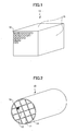
- FIG. 1 illustrates an example of the honeycomb unit 11, which is a rectangular solid having a square cross section.
- the honeycomb unit 11 includes plural through-holes 12 arranged in parallel from the front side to the back side, and outer side walls 13 without the through-holes.
- the wall thickness between the through-holes 12 is from 0.05 to 0.35 mm, more preferably, from 0.10 to 0.30 mm, still more preferably, from 0.15 to 0.25 mm.
- the strength of the honeycomb unit lowers; when the wall thickness between the through-holes 12 is greater than 0.35 mm, the area where the honeycomb unit can contact the exhaust gas decreases, and the exhaust gas cannot infiltrates into the partition wall sufficiently, thus, the exhaust gas cannot contact the catalyst elements carried in the inner portion of the partition wall, as a result, the catalyst performance may decline.
- the number of the through-holes 12 per unit cross-sectional area be from 15.5 to 186/cm 2 (from 100 to 1200 cpsi), more preferably, from 46.5 to 170.5/cm 2 (from 300 to 1100 cpsi), and still more preferably, from 62.0 to 155/cm 2 (from 400 to 1000 cpsi).
- the number of the through-holes 12 per unit cross-sectional area is less than 15.5, the area of the inner wall contacting the exhaust gas in the honeycomb units 11 becomes small, and when the number of the through-holes 12 per unit cross-sectional area is greater than 186, the pressure loss increases, and it becomes difficult to fabricate the honeycomb units 11.
- the cross section of the through-holes 12 may approximately be a triangle or a hexagon.
- the cross sectional area of the honeycomb unit 11 is from 5 to 50 cm 2 , more preferably, from 6 to 40 cm 2 , and still more preferably, from 8 to 30 cm 2 .
- the cross sectional area of the honeycomb unit 11 being from 5 to 50 cm 2 , it is possible to adjust the percentage of the sealing material layer 14 in the honeycomb structure, and hence, it is possible to maintain the specific-surface-area of the honeycomb structure to be large, highly disperse the catalyst elements, and maintain the shape of the honeycomb structure even when external forces like thermal shock and vibration are imposed.
- extrusion molding is performed by using a raw material paste with the above-mentioned ceramic particles, the inorganic fibers and/or whiskers, and the inorganic binder as main ingredients, thereby forming a honeycomb unit molding piece.
- a raw material paste with the above-mentioned ceramic particles, the inorganic fibers and/or whiskers, and the inorganic binder as main ingredients, thereby forming a honeycomb unit molding piece.
- an organic binder, a dispersive medium, and a molding agent may be added when necessary according to the moldability.
- the organic binders may be one or more selected from a group of methylcellulose, carboxymethylcellulose, hydroxyethylcellulose, polyethylene glycol, phenolic resin, and epoxy resin.
- the composition of the organic binders is 1 to 10 parts by weight (w/t part) assuming the total weight of the ceramic particles, the inorganic fibers and/or whiskers, and the inorganic binders is 100 parts by weight (w/t part).
- the dispersive medium may be water, organic solvent (like benzene), alcohol (like methanol), or others.
- the molding agent may be ethylene glycol, dextrin, aliphatic acid, fatty acid soap, polyalcohol, or others.
- the method of forming the raw material paste there is no limitation on the method of forming the raw material paste.
- mixing and kneading are preferable.
- a mixer or an agitator may be used for mixing, and a kneader may be used for kneading.
- a shape having the through holes can be formed by extrusion molding.
- the thus obtained honeycomb unit molding piece is dried.
- Any kind of dryer can be used, for example, use can be made of a microwave dryer, a hot air dryer, a dielectric dryer, a low-pressure dryer, a vacuum dryer, or a freezing dryer.
- the thus obtained molding piece is degreased.
- the degreasing conditions can be selected appropriately according to the types and amounts of organic materials included in the molding piece.
- degreasing is performed at a temperature of 400 °C for about two hours.
- the thus obtained molding piece is fired. There is no limitation on conditions of firing.
- firing is performed at a temperature from 600 °C to 1200 °C, more preferably, from 600 °C to 1000 °C. If the firing temperature is lower than 600 °C, sintering of the ceramic particles does not proceed, and the strength of the honeycomb structure may decrease. If the firing temperature is higher than 1200 °C, the ceramic particles are sintered too much, the specific surface-to area decreases, and the catalyst elements being carried cannot be highly dispersed.
- the honeycomb unit having plural through-holes can be formed.
- a sealing material which becomes the sealing material layer 14 is applied on the thus obtained honeycomb structure, and plural such honeycomb structures are bonded one by one, and are dried and fixed afterwards to fabricate a honeycomb structure.
- the sealing material may be a mixture of ceramic particles and an inorganic binder, or a mixture of an inorganic binder and an inorganic fiber, or a mixture of ceramic particles, an inorganic binder, and an inorganic fiber.
- an organic binder can be added to the sealing material.
- the organic binder may be one or more selected from a group of polyvinyl alcohol, methylcellulose, ethylcellulose, and carboxymethylcellulose.
- the sealing material be 0.5 to 2 mm in thickness. If the thickness of the sealing material is less than 0.5 mm, it is difficult to obtain sufficient bonding strength. Meanwhile, because the sealing material does not function as a catalyst carrier, if the thickness of the sealing material is greater than 2 mm, the specific surface-to area decreases, and when catalyst elements are being carried, the catalyst elements cannot be well dispersed.
- the number of the bonded honeycomb units can be appropriately decided according to the size of the honeycomb structure in use, which includes the bonded honeycomb units carrying the catalyst elements.
- the honeycomb structure can be appropriately cut or polished according to its size and shape in use.
- a coating material may be applied to the outside surface (side surfaces) of the honeycomb structure, on which the through-holes are not formed, and dried and fixed afterward to form a coating material layer. Due to this, it is possible to protect the outside surface and increase the strength.
- the coating material It may be formed from the same material as the sealing material, or from materials different from the sealing material.
- the composition of the coating material may be the same as that of the sealing material, or different from that of the sealing material.
- the thickness of the coating material there is no limitation on the thickness of the coating material.
- the coating material is 0.1 to 2 mm in thickness. If the thickness of the coating material is less than 0.1 mm, it is difficult.to protect the outside surface and increase the strength. Meanwhile, if the thickness of the coating material is greater than 2 mm, the specific surface-to area of the honeycomb structure decreases, and when catalyst elements are being carried, the catalyst elements cannot be well dispersed.
- the surface of the coating material may be processed by sand blasting, shot blasting, hydro-honing, polishing, or by a chisel to adjust the surface roughness Ra of the outer surface of the honeycomb structure.
- the surface roughness Ra of the outer surface of the honeycomb structure may also be adjusted by changing diameters or composition of the ceramic particles in the coating material.
- the polishing materials used in the sand blasting or the polishing material of a grind stone used for polishing may be an alumina-based powder, a silicon carbonide-based powder, a zirconia-based powder, ceramic beads, or a stainless powder.
- FIG. 2 is a schematic view of a cylindrical honeycomb structure 10 which is obtained by bonding plural solid rectangular honeycomb units 11 (refer to FIG. 1) each having a square cross section.
- the honeycomb units 11 are bonded together by the sealing material layer 14, and are cut into a cylindrical shape. Then, the outer surface of the honeycomb structure 10 without through-holes is covered by a coating material layer 16.
- the honeycomb structure 10 shown in FIG. 2 may be fabricated by shaping the cross sections of the honeycomb units into a square or a sector, and bonding these honeycomb units 11 together to form a certain shape (in FIG. 2, a cylindrical). In this case, cutting and polishing steps may be omitted.
- honeycomb structure 10 there is no limitation on applications of the thus obtained honeycomb structure 10.
- the honeycomb structure 10 may be used as a catalyst carrier for converting exhaust gas from vehicles.
- the honeycomb structure 10 when used as a catalyst carrier for converting exhaust gas from a Diesel engine, it may be used together with a Diesel particulate filter (DPF), which includes silicon carbide or other ceramic honeycomb structures to filter particulate materials (PM) in the exhaust gas, and has combustion purification functions.
- DPF Diesel particulate filter
- the honeycomb structure 10 of the present invention may be arranged in front (upstream) of or behind (downstream of) the DPF.
- honeycomb structure 10 When the honeycomb structure 10 is arranged in front of the DPF, if exothermic reactions occur in the honeycomb structure 10 of the present invention, heat can be transmitted to the DPF behind, thus increasing the temperature during regeneration of the DPF. In the meantime, when the honeycomb structure 10 is arranged behind the DPF, since the PM in the exhaust gas is filtered (burned) by the DPF so as to pass through the through-holes of the honeycomb structure, clogging can hardly occur. Further, when burning the PM by the DPF, gas compositions generated by incomplete combustion can also be processed.
- honeycomb structure can be used in applications as described above in the related art, and also can be used without carrying catalyst elements, for example, can be used as an absorbent for absorbing gas components or liquid components.
- the thus obtained honeycomb structure 10 can carry the catalyst to form a honeycomb catalyst.
- the catalyst may include one or more of a noble metal, an alkali metal, an alkali-earth metal, and an oxide.
- the noble metal may be platinum, palladium, rhodium, or others.
- the alkali metal may be potassium, sodium, or others.
- the alkali-earth metal may be barium or others.
- the oxide may be perovskite (such as, La 0.75 K 0.25 MnO 3 ), CeO 2 , or others.
- honeycomb catalyst there is no limitation on applications of the thus obtained honeycomb catalyst.
- the honeycomb catalyst it is preferable to use the honeycomb catalyst as a three way catalyst or an occlusion-type NOx catalyst.
- the catalyst may be carried after the honeycomb structure is fabricated, or may be carried at the stage of raw materials.
- honeycomb structures fabricated under various conditions are presented. It should be noted that the present invention is not limited to these examples.
- ⁇ alumina particles having average particle diameter of 2 ⁇ m
- silica alumina fibers having average fiber diameter of 10 ⁇ m, average fiber length of 100 ⁇ m, aspect ratio of 10
- silica sol solid concentration 30 weight %) in 50 parts by weight, serving as the raw materials of the inorganic binder
- methylcellulose in 6 parts by weight and tiny amounts of plasticizer and lubricant are added into the thus obtained mixture in 100 parts by weight, and are further mixed and kneaded, forming a mixture composition. Then, this mixture composition is extruded by using an extruder to perform extrusion molding, obtaining a raw molding piece.
- FIG. 3 presents a SEM (Scanning Electron Microscopy) picture of the wall surface of the honeycomb unit 11.
- FIG. 3 reveals that the silica-alumina fibers are arranged along the extrusion direction of the raw material paste.
- a heat-resistant sealing paste was prepared by mixing ⁇ alumina particles (having average particle diameter of 2 ⁇ m) in 29 parts by weight, silica alumina fibers (having average fiber diameter of 10 ⁇ m, and average fiber length of 100 ⁇ m) in 7 parts by weight, silica sol (solid concentration 30 weight %) in 34 parts by weight, carboxymethylcellulose in 5 parts by weight, and water in 25 parts by weight.
- silica sol solid concentration 30 weight %) in 34 parts by weight
- carboxymethylcellulose in 5 parts by weight
- water 25 parts by weight
- FIG. 4A is a schematic view of the honeycomb structure obtained by bonding plural honeycomb units 11, showing a cross section of the honeycomb structure having the through-holes.
- This honeycomb structure is fabricated by applying the sealing paste to the outside surface of the honeycomb structure to a thickness of 1 mm so as to bond the plural honeycomb units 11.
- a diamond cutter was used to cut the honeycomb structure into circular cylindrical shape so that the front face of the aggregate was of point symmetry, and the sealing paste was applied to the circular outside surface 16 without the through-holes 12 to a thickness of 0.5 mm to form a coating on the outside surface 16.
- the aggregate was dried at 120 °C, and maintained at 700 °C for two hours to degrease the sealing material layer and the coating material layer.
- a chisel is used to adjust the surface roughness.
- a circular cylindrical honeycomb structure 10 is obtained (diameter: 143.8 mm, length: 150 mm).
- Table 1 presents the unit cross sectional area of the honeycomb structure 10, the unit area ratio of the honeycomb structure 10, the sealing layer area ratio of the honeycomb structure 10, and the surface roughness Ra of the honeycomb structure 10.
- the unit cross sectional area of the honeycomb structure 10 is defined to be a ratio of a sum of the cross sectional areas of the honeycomb units to the cross sectional area of the honeycomb structure.
- a silica alumina fiber having a diameter of 10 ⁇ m, a length of 100 ⁇ m, and an aspect ratio of 10 is used as an inorganic fiber sample.
- the cross sectional area of the coating material layer is also included in the cross sectional area of the sealing material layer.
- the surface roughness Ra is obtained by measuring the surface roughness in the longitudinal direction at four positions equally separated by 90 degrees in the circumferential direction of the honeycomb structure.
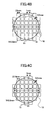
- Honeycomb structures 10 were fabricated in the same way as in the first example with the shapes of the honeycomb units to be those displayed in Table 1. Specifically, FIG. 4B, FIG. 4C, and FIG. 4D show honeycomb structures 10 of comparative example 1, example 2, and reference example 1, and FIG. 5A, FIG. 5B, and FIG. 5C show honeycomb structures 10 of example 3 and comparative examples 2, 3.
- the honeycomb structures 10 is formed integrally, hence, the bonding step and the cutting step were not performed.
- Honeycomb structures 10 were fabricated in the same way as in the first example with the surface roughness Ra to be the values shown in Table 1.
- the shapes of the honeycomb structures 10 of examples 4 - 6 and comparative examples 4, 5 are the same as that shown in FIG. 4A.
- Honeycomb units 11 were fabricated in the same way as in the first example by using titania particles (average particle diameter: 2 ⁇ m) as the ceramic particles with the shapes of the honeycomb units to be those displayed in Table 1.
- titania particles average particle diameter: 2 ⁇ m
- honeycomb structures 10 were fabricated.
- the shapes of the honeycomb structures 10 of reference example 2, comparative example 6, and reference examples 3, 4 are the same as those shown in FIG. 4A through FIG. 4D, and the shapes of the honeycomb structures 10 of reference example 5, and comparative examples 7, 8 are the same as those shown in FIG. 5A through FIG. 5C.
- the honeycomb structure 10 was formed integrally.
- Honeycomb units 11 were fabricated in the same way as in the first example by using silica particles (average particle diameter: 2 ⁇ m) as the ceramic particles with the shapes of the honeycomb units to be those displayed in Table 1. Next, in the same way as in the first example, except that silica particles (average particle diameter: 2 ⁇ m) were used as the ceramic particles of the sealing material layer and the coating material layer, honeycomb structures 10 were fabricated.
- the shapes of the honeycomb structures 10 of reference example 6, comparative example 9, and reference examples 7, 8 are the same as those shown in FIG. 4A through FIG. 4D, and the shapes of the honeycomb structures 10 of reference example 9 and comparative examples 10, 11 are the same as those shown in FIG. 5A through FIG. 5C.
- the honeycomb structure 10 was formed integrally.
- Honeycomb units 11 were fabricated in the same way as in the first example by using zirconia particles (average particle diameter: 2 ⁇ m) as the ceramic particles with the shapes of the honeycomb units to be those displayed in Table 1. Next, in the same way as in the first example, except that zirconia particles (average particle diameter: 2 ⁇ m) were used as the ceramic particles of the sealing material layer and the coating material layer, honeycomb structures 10 were fabricated.
- the shapes of the honeycomb structures 10 of reference example 10, comparative example 12, and reference examples 11, 12 are the same as those shown in FIG. 4A through FIG. 4D, and the shapes of the honeycomb structures 10 of reference example 13 and comparative examples 13, 14 are the same as those shown in FIG. 5A through FIG. 5C.
- the honeycomb structure 10 was formed integrally.
- a cylindrical cordierite-based honeycomb structure (diameter: 143.8 mm, length: 150 mm) available in the market, which has an alumina catalyst carrying layer inside the through-holes, was used.
- the cell shape was a hexagon, the cell density was 62/cm 2 (400 cpsi), and the wall thickness was 0.18 mm.
- the front view of the honeycomb structure is the same as that shown in FIG. 5C.
- Honeycomb units 11 were fabricated in the same way as in the first example by using silica-alumina fibers having the shapes shown in Table 2 as the inorganic fiber. Next, in the same way as in the first example, except that the silica-alumina fibers were used as the silica-alumina fibers of the sealing material layer and the coating material layer, honeycomb structures 10 were fabricated.
- the shapes of the honeycomb structures 10 of reference examples 14 through 18 are the same as that shown in FIG. 4A.
- ⁇ alumina particles are used as a ceramic particle sample, the unit area ratio is 93.5%, and the area ratio of the sealing layer area ratio and the coating material layer is 6.5%.
- Honeycomb structures 10 were fabricated in the same way as in the first example except that the cross sectional area of the honeycomb units and the thickness of the sealing material layer for bonding the honeycomb units 11 were changed to be those in Table 3.
- the shapes of the honeycomb structures 10 of reference examples 19, 20 are the same as that shown in FIG. 4A, and the shapes of the honeycomb structures 10 of reference examples 21, 22 are the same as that shown in FIG. 4C.
- ⁇ alumina particles were used as a ceramic particle sample, a silica alumina fiber having a diameter of 10 ⁇ m, a length of 100 ⁇ m, and an aspect ratio of 10 is used as an inorganic fiber sample.
- the cross sectional area of the coating material layer is also included in the cross sectional area of the sealing material layer.
- a honeycomb structure 10 was fabricated in the same way as in the first example except that an alumina sol (solid concentration 30 weight %) was used as the material of the inorganic binder, as shown in Table 3.
- Honeycomb structures 10 were fabricated in the same way as in the first example except that sepiolite, and attapulgite were used as the material of the inorganic binder, as shown in Table 3.
- ⁇ alumina particles having average particle diameter of 2 ⁇ m
- silica alumina fibers having average fiber diameter of 10 ⁇ m, and average fiber length of 100 ⁇ m, aspect ratio of 10
- a material of the inorganic binder in 15 parts by weight
- water in 35 parts by weight
- an organic binder, a plasticizer, and a lubricant were added into the thus obtained mixture, and the mixture was fired, thus obtaining the honeycomb units 11.
- the honeycomb units 11 were bonded to fabricate a honeycomb structure.
- the thus obtained honeycomb structure was cut, and the coating material layer 16 was applied, thereby, obtaining a circular cylindrical honeycomb structure 10 (diameter: 143.8 mm, length: 150 mm).
- a honeycomb structure 10 was fabricated in the same way as in the first example except that the inorganic binder was not used, as shown in Table 3.
- ⁇ alumina particles having average particle diameter of 2 ⁇ m
- silica alumina fibers having average fiber diameter of 10 ⁇ m, and average fiber length of 100 ⁇ m, aspect ratio of 10
- water in 35 parts by weight
- an organic binder, a plasticizer, and a lubricant were added into the above mixture, and the mixture was fired at 1000 °C, thus obtaining the honeycomb units 11.
- the honeycomb units 11 were bonded together to fabricate a honeycomb structure.
- the thus obtained honeycomb structure was cut, and the coating material layer 16 was applied, thereby, obtaining a circular cylindrical honeycomb structure 10 (diameter: 143.8 mm, length: 150 mm).
- the specific surface area of the honeycomb structure was measured in the following way. First, the volume of the honeycomb units 11 and the volume of the sealing material layer were calculated, and a calculation was made of a ratio A (volume %) of the materials of the honeycomb units 11 to the volume of the honeycomb structure. Next, a measurement was made of a BET specific surface area per unit weight of the honeycomb unit 11 (m 2 /g) (denoted as "B"). The BET specific surface area was measured by "one-point method" in compliance with JIS-R-1626 (1996) set forth in Japanese Industrial Standards by using a BET measurement device "Micrometitics” FlowSorb II-2300 (manufactured by Shimadzu Co.).
- the specific surface area of the honeycomb structure is defined to be the apparent specific surface area per volume of the honeycomb structure.
- the thermal shock test was performed in the following way.
- a heat insulating alumina mat made from alumina fibers (product name: MAFTEC, manufactured by Mitsubishi Chemistry Co., size: 46.5cm x 15cm, thickness: 6 mm) was wound on the outer surface of the honeycomb structure, and was disposed in a metal casing 21; the honeycomb structure together with the metal casing 21 was set in a firing furnace at 600 °C, and was heated for 10 minutes; then, the honeycomb structure was taken out from the firing furnace, and was quenched to the room temperature.
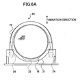
- FIG. 6A is a front view of a vibration device 20 used in the vibration test.
- FIG. 6B is a side view of the vibration device 20.
- the honeycomb structure in the metal casing 21 was placed on a stand 22, and was fixed with a U-shaped fixture 23 and a screw 24. Hence, the metal casing 21 was integrated with the stand 22 and the fixture 23, and they could shake together.
- the vibration test was performed with a frequency of 160 MHz, an accelerator of 30 G, amplitude of 0.58 mm, a holding time of 10 hours, and at the room temperature, with the vibrating direction being in the Z-axis direction.
- the thermal shock test and the vibration test were executed alternately for 10 times, respectively.
- G 100 x (T0 - Ti)/T0.
- a pressure loss of the honeycomb structure was measured in the following way.
- FIG. 7 is a view of a pressure loss measurement device 40.
- a honeycomb structure wound by an alumina mat was set in a metal casing, and the honeycomb structure together with the metal casing 21 was placed in an exhaust pipe of a 2L common-rail Diesel engine, and pressure gages were attached to the front side and back side of the honeycomb structure to measure the pressure difference.
- the measurement was performed with the number of revolution of the engine to be 1500 rpm, and the torque was set to be 50 Nm, and the pressure difference after the engine started running for 5 minutes was measured.
- a heat insulating alumina mat made from alumina fibers (product name: MAFTEC, manufactured by Mitsubishi Chemistry Co., size: 46.5cm x 15cm, thickness: 6 mm) was wound on the outer surface of the honeycomb structure, and was disposed in a metal casing 21; the honeycomb structure together with the metal casing 21 was set in the vibration device 20 as shown in FIG. 6A and FIG. 6B, so that the honeycomb structure was shaken such that the through-holes were moved to the horizontal direction.
- the vibration was performed, and the slippage was measured, in the same way as described above except that the holding time was 120 hours, and the number of repetition was 1. Specifically, when the magnitude of the slippage is less than 1 mm, the result is represented by a circle, when the slippage is less than 10 mm and greater than 1 mm, the result is represented by a triangle, and when the slippage is greater than 10 mm, the result is represented by a cross.
- Table 4 presents evaluation results of the weight reduction rate G in the repetitive thermal shock and vibration test, the pressure loss, and the slippage.
- a silica alumina fiber having a diameter of 10 ⁇ m, a length of 100 ⁇ m, and an aspect ratio of 10 is used as an inorganic fiber sample.
- FIG. 8 are plots showing the evaluation results, where the abscissa represents the cross sectional area of the honeycomb unit, the ordinate represents the weight reduction rate G in the repetitive thermal shock and vibration test and the pressure loss.
- the specific surface area of the honeycomb structure increases, and the resistance against thermal shock and vibration becomes high.
- the surface roughness Ra of the honeycomb structure being from 1 ⁇ m to 50 ⁇ m, it is possible to prevent the honeycomb structure from being removed from a vessel holding the honeycomb structure.
- FIG. 9 are plots showing the evaluation results , where the abscissa represents the area ratio of the honeycomb unit, the ordinate represents the weight reduction rate G in the repetitive thermal shock and vibration test and the pressure loss.
- the specific surface area of the honeycomb structure can be increased, the resistance against thermal shock and vibration becomes high, and the pressure loss decreases.
- the pressure loss decreases significantly when the area ratio of the honeycomb units being greater than 90%.
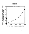
- Table 5 shows measurement results of example 1, references 14 to 18 in which the aspect ratios of the inorganic fibers are varied. Specifically, Table 5 includes results of the diameter, length, the aspect ratio of the inorganic fiber, the specific surface area of the honeycomb unit 11, the specific surface area S of the honeycomb structure, the weight reduction rate G in the repetitive thermal shock and vibration test, and the pressure loss.
- ⁇ alumina particles are used as a ceramic particle sample.
- FIG. 10 are plots showing the evaluation results, where the abscissa represents the aspect ratio of the inorganic fiber, the ordinate represents the weight reduction rate G in the repetitive thermal shock and vibration test and the pressure loss.
- the aspect ratio of the inorganic fiber being from 2 to 1000, the resistance against thermal shock and vibration becomes high.
- Table 6 shows measurement results of references 23 to 25 in which the types of the inorganic binders are changed, and results of references 26 in which the inorganic binder is not added. Specifically, Table 6 includes results of types of the inorganic binders, firing temperature of the honeycomb unit 11, the area ratio of the honeycomb unit 11, the specific surface area of the honeycomb unit 11, the specific surface area S of the honeycomb structure, the weight reduction rate G in the repetitive thermal shock and vibration test, and the pressure loss.
- ⁇ alumina particles are used as a ceramic particle sample, and a silica alumina fiber having a diameter of 10 ⁇ m, a length of 100 ⁇ m, and an aspect ratio of 10 is used as an inorganic fiber sample, and the unit shape is a 3.43 cm square.
- honeycomb structure 10 was immersed in a platinum nitrate solution, and adjustment was made so that the platinum was carried by the honeycomb structure with the weight of platinum per unit volume of the honeycomb structure being 2g/L. Then, this composition was maintained at 600 °C for one hour, thereby obtaining a honeycomb catalyst.
- the present invention can be used as a carrier of a catalyst for converting exhaust gas from a vehicle.
- the present invention can be used as an absorbent for absorbing gas components or liquid components.
Landscapes
- Chemical & Material Sciences (AREA)
- Inorganic Chemistry (AREA)
- Engineering & Computer Science (AREA)
- Ceramic Engineering (AREA)
- Life Sciences & Earth Sciences (AREA)
- Geology (AREA)
- Chemical Kinetics & Catalysis (AREA)
- Catalysts (AREA)
- Exhaust Gas After Treatment (AREA)
- Ceramic Products (AREA)
Abstract
Description
- The present invention relates to a honeycomb structure.
- Generally, a honeycomb catalyst, which is used for conversion of exhaust gas from vehicles, is fabricated by disposing materials of a high specific surface-to area like active alumina and catalysts like platinum on the surface of a monolithic cordierite-based honeycomb structure having a low thermal expansion characteristic. In addition, the honeycomb catalyst carries an alkali-earth metal like barium to act as an occlusion-type NOx catalyst for a processing NOx in an oxygen-rich atmosphere, such as atmospheres in a lean-burn engine or a Diesel engine.
- In order to further improve conversion performance, it is necessary to increase the contact probability between the exhaust gas and the catalyst element and the NOx occlusion agent as well. For this purpose, it is required to increase the specific surface-to area of the carrier, decrease diameters of catalyst elements and highly disperse the catalyst elements. However, if simply increasing the amount of the materials of high specific surface-to areas like active alumina, it is the thickness of the active alumina layer only that is increased, and it does not lead to an increase of the contact probability, but results in a pressure loss. For this reason, modifications have been made on cell shapes, cell densities, wall thicknesses, and so on. For example, see
JP-A10-263416 reference 1"). - On the other hand, a honeycomb structure formed from materials of high specific surface-to areas is known to be formed by extrusion molding of the materials of high specific surface-to areas together with inorganic fibers and inorganic binders. For example, see
JP-A5-213681 reference 2"). - Further, a honeycomb structure is known, which is obtained by bonding honeycomb units with an adhesive agent in order to increase the size of the above honeycomb structure. For example, see
DE4341159A1 (below, referred to as "reference 3"). - However, the above-mentioned techniques in the related art suffer from the following problems.
- Active alumina or other high specific surface-to area materials undergoes firing due to thermal-ageing, and thereby, the specific surface-to area decreases. Further, a catalyst like platinum, which is being carried, aggregates along with that, and the particle diameter thereof increases, thereby, the specific surface-to area decreases. In other words, after the thermal ageing (namely, after being used as a catalyst carrier), in order to have a specific surface-to area, it is necessary to the specific surface-to area at the initial stage. In addition, as described above, in order to further improve conversion performance, it is necessary to increase the contact probability between the exhaust gas and the catalyst element and the NOx occlusion agent as well. For this purpose, it is required to increase the specific surface-to area of the carrier, decrease diameters of catalyst elements and highly disperse the catalyst elements.
- However, concerning the honeycomb catalyst disclosed in
reference 1, in which high specific surface-to area materials like active alumina and catalysts like platinum are disposed on the surface of a cordierite-based honeycomb structure, in order to increase the contact probability with the exhaust gas, modifications have been made on cell shapes, cell densities, wall thicknesses, and others to increase the specific surface-to area of the catalyst carrier. However, the specific surface-to area is not adequate. For this reason, the catalyst elements are not well dispersed, and the ability of converting the exhaust gas after thermal ageing is not sufficient. To solve this problem, it is attempted to have a larger amount of catalyst elements being carried, or to increase the size of the catalyst carrier. - However, catalysts like platinum are very expensive, and are valuable resources of quite limited amounts. In addition, when disposing the catalyst carrier in a vehicle, the space for disposing the catalyst carrier is quite limited. So far, there is not an appropriate solution to the problem.
- As for the honeycomb structure disclosed in
reference 2, because it is formed by extrusion molding of the materials of high specific surface-to areas together with the inorganic fibers and inorganic binders, and because the base material is of a high specific surface-to area, the catalyst carrier is also of a high specific surface-to area, it is possible to well disperse the catalyst elements. However, in order to maintain the specific surface-to area of the base material, like alumina, firing cannot be performed too much, due to this, the strength of the base is weak. In addition, when disposing the catalyst carrier in a vehicle, the space for disposing the catalyst carrier is quite limited. For this reason, in order to increase the specific surface-to area of the carrier, it is attempted to reduce the thickness of the partition wall. But as a result, the strength of the base material becomes weaker. In addition, since the thermal expansion coefficient of alumina is large, cracks occur easily during firing (calcination) and usage. Considering these factors, when being used in a vehicle, since external forces are imposed, such as thermal stress caused by a rapid temperature change during usage, or strong vibration, the honeycomb structure is liable to be broken, and it is difficult to maintain the shape of the honeycomb structure to function as a catalyst carrier. - As for catalyst carrier disclosed in reference 3, the purpose is to increase the size of the honeycomb structure, and a catalyst carrier having a cross sectional area greater than 200 cm2 is reported. When thermal stress caused by a rapid temperature change is imposed, further, when strong vibration is imposed, as described above, the honeycomb structure is liable to be broken, and it is difficult to maintain the shape of the honeycomb structure to function as a catalyst carrier.
- Further, when a cylindrical honeycomb structure is held inside a vessel formed from stainless steel or other metals for storage to obtain a canning structure, because of the exhaust gas pressure and vibration, the honeycomb structure may be removed from the vessel.
- Accordingly, it is a general object of the present invention to solve one or more problems of the related art.
- A specific object of the present invention is to solve the above problems by providing a honeycomb structure having high resistance against thermal shock and vibration, allowing catalyst elements to be highly dispersed, and able to prevent the honeycomb structure from being removed from a vessel holding the honeycomb structure.
- The present invention provides a honeycomb structure including a plurality of honeycomb units bonded together by using a sealing material layer, each of the honeycomb units including a plurality of through-holes separated by a plurality of partition walls and provided in parallel along a longitudinal direction of the honeycomb units; wherein a surface roughness Ra of an outer surface of the honeycomb structure is greater than or equal to 1 µm and less than or equal to 50 µm; each of the honeycomb units includes at least ceramic particles, inorganic fibers, and/or whisker; and an area of a cross section of one of the honeycomb units perpendicular to the longitudinal direction of the one of the honeycomb units is greater than or equal to 5 cm2 and less than or equal to 50 cm2.
- According to the present invention, it is possible to provide a honeycomb structure having high resistance against thermal shock and vibration, allowing catalyst elements to be highly dispersed, and able to prevent the honeycomb structure from being removed from a vessel holding the honeycomb structure.
- In addition, in the honeycomb structure, preferably a ratio of a sum of areas of the cross sections of the honeycomb units perpendicular to the longitudinal direction of the honeycomb units to an area of a cross section of the honeycomb structure perpendicular to the longitudinal direction of the honeycomb structure is greater than or equal to 85 %.
- According to the present invention, it is possible to relatively increase the surface area available for carrying catalyst elements and relatively decrease a pressure loss.
- In addition, in the honeycomb structure, preferably a coating material layer is provided on an outer surface of the honeycomb structure.
- According to the present invention, it is possible to protect the outer surface and thus to improve strength of the honeycomb structure.
- In addition, in the honeycomb structure, preferably the ceramic particles include one or more selected from a group of alumina, silica, zirconia, titanium, cerium, mullite, and zeolite.
- According to the present invention, it is possible to improve the specific surface area.
- In addition, in the honeycomb structure, preferably the inorganic fibers and/or the whisker includes one or more selected from a group of alumina, silica, silicon carbide, silica alumina, glass, potassium titanate, and aluminum borate.
- According to the present invention, it is possible to improve strength of the honeycomb units.
- In addition, in the honeycomb structure, preferably each of the honeycomb units is formed from a mixture of the ceramic particles, the inorganic fibers and/or the whisker, and an inorganic binder, and the inorganic binder includes one or more selected from a group of alumina sol, silica sol, titanium sol, soluble glass, sepiolite, and attapulgite.
- According to the present invention, it is possible to obtain sufficient strength even at a low firing temperature of the honeycomb units.
- In addition, preferably the honeycomb structure carries catalyst elements.
- According to the present invention, it is possible to obtain a honeycomb catalyst allowing catalyst elements to be highly dispersed.
- In addition, in the honeycomb structure, preferably the catalyst elements include one or more of a noble metal, an alkali metal, an alkali-earth metal, and an oxide.
- According to the present invention, it is possible to improve the conversion capability.
- In addition, preferably, the honeycomb structure is used to convert exhaust gas from a vehicle.
- Therefore, according to the present invention, it is possible to provide a honeycomb structure having high resistance against thermal shock and vibration, allowing catalyst elements to be highly dispersed, and able to prevent the honeycomb structure from being removed from a vessel holding the honeycomb structure.
- These and other objects, features, and advantages of the present invention will become more apparent from the following detailed description of preferred embodiments given with reference to the accompanying drawings.
-
- FIG. 1 is a schematic view of honeycomb units of the present invention;
- FIG. 2 is a schematic view of a honeycomb structure of the present invention;
- FIG. 3 is a SEM (Scanning Electron Microscopy) picture of a wall surface of the honeycomb structure of the present invention;
- FIG. 4A is a schematic view of the honeycomb structure obtained by bonding plural honeycomb units, showing a cross section of the honeycomb structure having the through-holes;
- FIG. 4B is a schematic view of the honeycomb structure obtained by bonding plural honeycomb units, showing a cross section of the honeycomb structure having the through-holes;
- FIG. 4C is a schematic view of the honeycomb structure obtained by bonding plural honeycomb units, showing a cross section of the honeycomb structure having the through-holes;
- FIG. 4D is a schematic view of the honeycomb structure obtained by bonding plural honeycomb units, showing a cross section of the honeycomb structure having the through-holes;
- FIG. 5A is a schematic view of the honeycomb structure obtained by bonding plural honeycomb units, showing a cross section of the honeycomb structure having the through-holes;
- FIG. 5B is a schematic view of the honeycomb structure obtained by bonding plural honeycomb units, showing a cross section of the honeycomb structure having the through-holes;
- FIG. 5C is a schematic view of the honeycomb structure obtained by one honeycomb unit, showing a cross section of the honeycomb structure having the through-holes;
- FIG. 6A is a front view of a
vibration device 20; - FIG. 6B is a side view of the
vibration device 20; - FIG. 7 is a view of a pressure
loss measurement device 40; - FIG. 8 shows the relationship between the cross sectional area of the honeycomb unit and the weight reduction rate G and the pressure loss of the honeycomb unit;
- FIG. 9 shows the relationship between the area ratio of the honeycomb unit and the weight reduction rate G and the pressure loss of the honeycomb unit; and
- FIG. 10 shows the relationship between the aspect ratio of the silica alumina fiber and the weight reduction rate G and the pressure loss of the honeycomb unit.
- Below, embodiments of the present invention are explained with reference to the accompanying drawings.
- As illustrated in FIG. 1 and FIG. 2, a
honeycomb structure 10 of the present invention includesplural honeycomb units 11 bonded together by using a sealingmaterial layer 14, each of the honeycomb units including plural through-holes 12 separated by plural partition walls and provided in parallel along a longitudinal direction of thehoneycomb units 11. A surface roughness Ra of an outer surface of thehoneycomb structure 10 is greater than or equal to 1 µm and less than or equal to 50 µm, each of thehoneycomb units 11 includes at least ceramic particles, inorganic fibers, and/or whisker, and an area of a cross section of one of the honeycomb units perpendicular to the longitudinal direction of the one of the honeycomb units is greater than or equal to 5 cm2 and less than or equal to 50 cm2. - In the
above honeycomb structure 10, because plural honeycomb units are bonded together by using the sealingmaterial layer 14, it is possible to improve the resistance against thermal shock and vibration. It is considered that this is because temperature differences between honeycomb units can be suppressed to be small even when a temperature distribution is generated in thehoneycomb structure 10 due to a rapid temperature change. Alternatively, this is because the sealingmaterial layer 14 is able to attenuate the thermal shock and vibration. - In addition, even when cracks occur in the honeycomb units because of thermal stress, the sealing
material layer 14 is able to prevent the cracks from propagating throughout the whole honeycomb structure. Further, the sealingmaterial layer 14 also functions as a frame of the honeycomb structure to maintain the shape of the honeycomb structure so as not to lose the function of a catalyst carrier. - When the area of a cross section of one honeycomb unit perpendicular to the longitudinal direction is less than 5 cm2 (or a cross section of one honeycomb unit perpendicular to the through-holes) (below, the area of such a cross section is simply referred to as "cross sectional area"), the ratio of the sealing
material layer 14, which seal the honeycomb units, becomes high, thus, the specific surface-to area decreases, and the pressure loss increases. In the meantime, when the cross sectional area is greater than 50 cm2, the honeycomb units become large, and it becomes difficult to attenuate the thermal stress in each of the honeycomb units. - Therefore, preferably, with the cross sectional area of the honeycomb unit being in the range from 5 to 50 cm2, it is possible to reduce the pressure loss, maintain sufficient strength against the thermal stress, while maintaining a large specific surface, and obtain high durability, and reach a practical use level.
- According to the honeycomb structure of the present invention, it is possible to highly disperse the catalyst elements and improve resistance against thermal shock and vibration.
- Here, when the honeycomb structure includes plural honeycomb units each having different cross sectional area, the term "cross sectional area" means the cross sectional area of each honeycomb unit, which is the basic unit constituting the honeycomb structure, and usually, means the maximum cross sectional area of the honeycomb unit.
- In the honeycomb structure of the present invention, the surface roughness Ra of the outer surface of the honeycomb structure is greater than or equal to 1 µm and less than or equal to 50 µm. When the honeycomb structure is used to convert exhaust gas from a vehicle, usually, the honeycomb structure is held inside a vessel formed from stainless steel or other metals for storage to obtain a canning structure. In this case, if the surface roughness Ra of the outer surface of the honeycomb structure is greater than or equal to 1 µm and less than or equal to 50 µm, when the honeycomb structure of the present invention is used as a canning structure, it is possible to prevent position slippage caused by vibration, and prevent damage to the honeycomb structure caused by the position slippage.
- If the surface roughness Ra of the outer surface of the honeycomb structure is greater than 50 µm, when the honeycomb structure of the present invention is used as a canning structure, because of a exhaust gas pressure and vibration, position slippage may occur easily, and the honeycomb structure may be damaged. This is because when the surface roughness Ra of the outer surface is high, the holding force due to the canning structure has a large distribution, a part of the thermal stress produced between the honeycomb unit and the coating material layer cannot be attenuated sufficiently, cracks occur in the coating material layer, and this makes the honeycomb unit be liable to be separated, and cannot be held.
- If the surface roughness Ra of the outer surface of the honeycomb structure is too small, a friction force sufficient for preventing position slippage. Therefore, it is preferable that the surface roughness Ra of the outer surface of the honeycomb structure be greater than or equal to 1 µm.
- In the present invention, preferably, in almost the entire outer surface of the honeycomb structure, the surface roughness Ra is in the range from 1 µm to 50 µm.
- The surface roughness Ra is defined to be an arithmetic average roughness in a specified direction measured by JIS B0601-2001 (corresponding to the international standard ISO4287-1997), and is obtained by calculating an average of absolute deviations from an average line of an uneven surface including depressions and projections. Hence, a surface roughness Ra in the longitudinal direction means a surface roughness Ra calculated in the above way from results measured in the longitudinal direction, and a surface roughness Ra in the circumferential direction means a surface roughness Ra calculated in the above way from results measured in a direction perpendicular to the longitudinal direction.
- In addition, preferably, a ratio of a sum of areas of the cross sections of the honeycomb units perpendicular to the longitudinal direction of the honeycomb units to an area of a cross section of the honeycomb structure perpendicular to the longitudinal direction of the honeycomb structure is greater than or equal to 85%, more preferably, greater than or equal to 90%. Below, such a cross section is simply referred to as "cross section")
- If the ratio is less than 85%, the ratio of the sealing
material layer 14 heightens, the ratio of the honeycomb units lowers, and thus, the specific surface-to area decreases and the pressure loss increases. If the ratio is higher than 90%, the pressure loss can be reduced. - The
honeycomb structure 10 of the present invention, as illustrated in FIG. 2, includesplural honeycomb units 11 bonded together by the sealingmaterial layer 14, and the outer surface of the honeycomb structure without through-holes may be covered by acoating material layer 16. Due to this, the outer surface can be protected and to improve the strength of the honeycomb structure. - There is no limitation on the shape of the honeycomb structure obtained by bonding
plural honeycomb units 11 together, and it can be of any shape and any size. For example, the honeycomb structure may be circular cylindrical, a rectangular pillar, or a cylindroid. - In the
honeycomb structure 10 of the present invention, the honeycomb unit may include inorganic fibers and/or whisker, hence it is possible to improve the strength of the honeycomb unit. Preferably, the aspect ratio (length/width) of the inorganic fibers and/or whiskers is from 2 to 1000, more preferably, from 5 to 800, still more preferably, from 10 to 500. When the aspect ratio of the inorganic fibers and/or whiskers is less than 2, the contribution to the strength of the honeycomb structure is small; when the aspect ratio of the inorganic fibers and/or the whiskers is greater than 1000, during molding, clogging may occurs in the mold, and it is difficult to perform molding. In addition, during extrusion molding, the inorganic fibers and/or the whiskers may be bent, making their lengths un-uniform, and this may reduce the contribution to the strength of the honeycomb structure. Here, when the aspect ratio of the inorganic fibers and/or whiskers has a distribution, the average value of the distribution may be used in the above discussion. - There is no limitation on the inorganic fibers or the whiskers, preferably, the inorganic fibers and/or the whiskers may be one or more selected from a group of alumina, silica, silicon carbide, silica alumina, glass, potassium titanate, and aluminum borate.
- Preferably, the concentration of the inorganic fibers and/or the whiskers included in the honeycomb structure is from 3% to 70% in weight, more preferably from 3% to 50% in weight, still more preferably, from 5% to 40% in weight, and yet more preferably, from 8% to 30% in weight. When the concentration of the inorganic fibers and/or the whiskers is less than 3% in weight, the percentage of the inorganic fibers and/or the whiskers, which contribute to the strength, is small; hence, the strength of the honeycomb structure decreases. When the concentration of the inorganic fibers and/or the whiskers is greater than 50% in weight, the percentage of the ceramic particles, which particles contribute to the specific surface-to area, is small, and the specific surface-to area of the honeycomb structure decreases; as a result, when carrying the catalyst elements, the catalyst elements cannot be well dispersed.
- In the
honeycomb structure 10 of the present invention, the honeycomb unit may include ceramic particles, and this improves the specific surface-to area of the honeycomb structure. - There is no limitation on the ceramic particles. For example, it is preferable to use one or more selected from a group of alumina, silica, zirconia, titanium, cerium, mullite, and zeolite. It is more preferable to use alumina.
- Preferably, the concentration of the ceramic particles included in the honeycomb structure is from 30% to 97% in weight, more preferably, from 30% to 90% in weight, still more preferably, from 40% to 80% in weight, yet more preferably, from 50% to 70% in weight. When the concentration of the ceramic particles is less than 30% in weight, the percentage of the ceramic particles, which contribute to the specific surface-to area, is small, and the specific surface-to area of the honeycomb structure decreases; as a result, when carrying the catalyst elements, the catalyst elements cannot be well dispersed. Meanwhile, when the concentration of the ceramic particles is higher than 97% in weight, the percentage of the inorganic fibers, which contribute to the strength, is small; as a result, the strength of the honeycomb structure decreases.
- In the
honeycomb structure 10 of the present invention, the honeycomb unit may be formed from a mixture of ceramic particles, inorganic fibers and/or whiskers, and an inorganic binder. Due to this, it is possible to obtain sufficient strength even at a low firing temperature of the honeycomb units. - There is no limitation on the inorganic binder. For example, the inorganic binder may be an inorganic sol, or a clay sol. Specifically, the inorganic sol may be an alumina sol, silica sol, titanium sol, or soluble glass. The clay sol may be a china clay, kaolin, montmorillonite, multiple chain structure clay such as sepiolite, or attapulgite. One or more of these inorganic sols and clay sols may be mixed for use.
- Preferably, the concentration of the inorganic binders included in the honeycomb structure is less than 50% in weight, more preferably, from 5% to 50% in weight, still more preferably, from 10% to 40% in weight, and yet still more preferably, from 15% to 35% in weight. When the concentration of the inorganic binders is greater than 50% in weight, it is difficult to perform molding.
- There is no limitation on the shape of the honeycomb units, but it is preferable to use shapes facilitating bonding of the honeycomb units. For example, a cross section of the honeycomb unit may be a square, or rectangle, or a sector.
- FIG. 1 illustrates an example of the
honeycomb unit 11, which is a rectangular solid having a square cross section. Thehoneycomb unit 11 includes plural through-holes 12 arranged in parallel from the front side to the back side, andouter side walls 13 without the through-holes. - There is no limitation on the wall thickness between the through-
holes 12. Preferably, the wall thickness between the through-holes 12 is from 0.05 to 0.35 mm, more preferably, from 0.10 to 0.30 mm, still more preferably, from 0.15 to 0.25 mm. When the wall thickness between the through-holes 12 is less than 0.05 mm, the strength of the honeycomb unit lowers; when the wall thickness between the through-holes 12 is greater than 0.35 mm, the area where the honeycomb unit can contact the exhaust gas decreases, and the exhaust gas cannot infiltrates into the partition wall sufficiently, thus, the exhaust gas cannot contact the catalyst elements carried in the inner portion of the partition wall, as a result, the catalyst performance may decline. - In addition, it is preferable that the number of the through-
holes 12 per unit cross-sectional area be from 15.5 to 186/cm2 (from 100 to 1200 cpsi), more preferably, from 46.5 to 170.5/cm2 (from 300 to 1100 cpsi), and still more preferably, from 62.0 to 155/cm2 (from 400 to 1000 cpsi). When the number of the through-holes 12 per unit cross-sectional area is less than 15.5, the area of the inner wall contacting the exhaust gas in thehoneycomb units 11 becomes small, and when the number of the through-holes 12 per unit cross-sectional area is greater than 186, the pressure loss increases, and it becomes difficult to fabricate thehoneycomb units 11. - There is no limitation on the shape of the through-
holes 12 of thehoneycomb units 11. For example, the cross section of the through-holes 12 may approximately be a triangle or a hexagon. - Preferably, the cross sectional area of the
honeycomb unit 11 is from 5 to 50 cm2, more preferably, from 6 to 40 cm2, and still more preferably, from 8 to 30 cm2. With the cross sectional area of thehoneycomb unit 11 being from 5 to 50 cm2, it is possible to adjust the percentage of the sealingmaterial layer 14 in the honeycomb structure, and hence, it is possible to maintain the specific-surface-area of the honeycomb structure to be large, highly disperse the catalyst elements, and maintain the shape of the honeycomb structure even when external forces like thermal shock and vibration are imposed. - Next, descriptions are made of a method of fabricating the honeycomb structure of the present invention. First, extrusion molding is performed by using a raw material paste with the above-mentioned ceramic particles, the inorganic fibers and/or whiskers, and the inorganic binder as main ingredients, thereby forming a honeycomb unit molding piece. In the raw material paste, in addition to the above materials, an organic binder, a dispersive medium, and a molding agent may be added when necessary according to the moldability.
- There is no limitation on the organic binders. For example, the organic binders may be one or more selected from a group of methylcellulose, carboxymethylcellulose, hydroxyethylcellulose, polyethylene glycol, phenolic resin, and epoxy resin. Preferably, the composition of the organic binders is 1 to 10 parts by weight (w/t part) assuming the total weight of the ceramic particles, the inorganic fibers and/or whiskers, and the inorganic binders is 100 parts by weight (w/t part).
- There is no limitation on the dispersive medium. For example, the dispersive medium may be water, organic solvent (like benzene), alcohol (like methanol), or others.
- There is no limitation on the molding agent; for example, the molding agent may be ethylene glycol, dextrin, aliphatic acid, fatty acid soap, polyalcohol, or others.
- There is no limitation on the method of forming the raw material paste. For example, mixing and kneading are preferable. For example, a mixer or an agitator may be used for mixing, and a kneader may be used for kneading.
- There is no limitation on the method of molding the raw material paste. For example, a shape having the through holes can be formed by extrusion molding.
- Next, preferably, the thus obtained honeycomb unit molding piece is dried. Any kind of dryer can be used, for example, use can be made of a microwave dryer, a hot air dryer, a dielectric dryer, a low-pressure dryer, a vacuum dryer, or a freezing dryer. In addition, preferably, the thus obtained molding piece is degreased. There is no limitation on conditions of degreasing, but the degreasing conditions can be selected appropriately according to the types and amounts of organic materials included in the molding piece. Preferably, degreasing is performed at a temperature of 400 °C for about two hours. Preferably, the thus obtained molding piece is fired. There is no limitation on conditions of firing. Preferably, firing is performed at a temperature from 600 °C to 1200 °C, more preferably, from 600 °C to 1000 °C. If the firing temperature is lower than 600 °C, sintering of the ceramic particles does not proceed, and the strength of the honeycomb structure may decrease. If the firing temperature is higher than 1200 °C, the ceramic particles are sintered too much, the specific surface-to area decreases, and the catalyst elements being carried cannot be highly dispersed.
- Through the above steps, the honeycomb unit having plural through-holes can be formed.
- Next, a sealing material, which becomes the sealing
material layer 14, is applied on the thus obtained honeycomb structure, and plural such honeycomb structures are bonded one by one, and are dried and fixed afterwards to fabricate a honeycomb structure. - There is no limitation on the sealing material. For example, the sealing material may be a mixture of ceramic particles and an inorganic binder, or a mixture of an inorganic binder and an inorganic fiber, or a mixture of ceramic particles, an inorganic binder, and an inorganic fiber. Further, an organic binder can be added to the sealing material. There is no limitation on the organic binder. For example, the organic binder may be one or more selected from a group of polyvinyl alcohol, methylcellulose, ethylcellulose, and carboxymethylcellulose.
- It is preferably that the sealing material be 0.5 to 2 mm in thickness. If the thickness of the sealing material is less than 0.5 mm, it is difficult to obtain sufficient bonding strength. Meanwhile, because the sealing material does not function as a catalyst carrier, if the thickness of the sealing material is greater than 2 mm, the specific surface-to area decreases, and when catalyst elements are being carried, the catalyst elements cannot be well dispersed. The number of the bonded honeycomb units can be appropriately decided according to the size of the honeycomb structure in use, which includes the bonded honeycomb units carrying the catalyst elements. The honeycomb structure can be appropriately cut or polished according to its size and shape in use.
- A coating material may be applied to the outside surface (side surfaces) of the honeycomb structure, on which the through-holes are not formed, and dried and fixed afterward to form a coating material layer. Due to this, it is possible to protect the outside surface and increase the strength.
- There is no limitation on the coating material. It may be formed from the same material as the sealing material, or from materials different from the sealing material. In addition, the composition of the coating material may be the same as that of the sealing material, or different from that of the sealing material.
- There is no limitation on the thickness of the coating material. Preferably, the coating material is 0.1 to 2 mm in thickness. If the thickness of the coating material is less than 0.1 mm, it is difficult.to protect the outside surface and increase the strength. Meanwhile, if the thickness of the coating material is greater than 2 mm, the specific surface-to area of the honeycomb structure decreases, and when catalyst elements are being carried, the catalyst elements cannot be well dispersed.
- The surface of the coating material may be processed by sand blasting, shot blasting, hydro-honing, polishing, or by a chisel to adjust the surface roughness Ra of the outer surface of the honeycomb structure. Alternatively, the surface roughness Ra of the outer surface of the honeycomb structure may also be adjusted by changing diameters or composition of the ceramic particles in the coating material. The polishing materials used in the sand blasting or the polishing material of a grind stone used for polishing may be an alumina-based powder, a silicon carbonide-based powder, a zirconia-based powder, ceramic beads, or a stainless powder.
- After plural honeycomb units are bonded with the sealing materials (when the coating materials are provided, after the coating material layers are formed), it is preferable to perform calcination. In doing so, it is possible to degrease the organic binder when the organic binder is included in the sealing materials and the coating materials. The degreasing conditions may be determined appropriately according to types and loadings of the organic materials. Preferably, calcination is performed at 700 °C for two hours. As an example of the honeycomb structure, FIG. 2 is a schematic view of a
cylindrical honeycomb structure 10 which is obtained by bonding plural solid rectangular honeycomb units 11 (refer to FIG. 1) each having a square cross section. To form thehoneycomb structure 10, thehoneycomb units 11 are bonded together by the sealingmaterial layer 14, and are cut into a cylindrical shape. Then, the outer surface of thehoneycomb structure 10 without through-holes is covered by acoating material layer 16. Alternatively, thehoneycomb structure 10 shown in FIG. 2, for example, may be fabricated by shaping the cross sections of the honeycomb units into a square or a sector, and bonding thesehoneycomb units 11 together to form a certain shape (in FIG. 2, a cylindrical). In this case, cutting and polishing steps may be omitted. - There is no limitation on applications of the thus obtained
honeycomb structure 10. For example, it is preferable to use thehoneycomb structure 10 as a catalyst carrier for converting exhaust gas from vehicles. In addition, when thehoneycomb structure 10 is used as a catalyst carrier for converting exhaust gas from a Diesel engine, it may be used together with a Diesel particulate filter (DPF), which includes silicon carbide or other ceramic honeycomb structures to filter particulate materials (PM) in the exhaust gas, and has combustion purification functions. In this case, thehoneycomb structure 10 of the present invention may be arranged in front (upstream) of or behind (downstream of) the DPF. When thehoneycomb structure 10 is arranged in front of the DPF, if exothermic reactions occur in thehoneycomb structure 10 of the present invention, heat can be transmitted to the DPF behind, thus increasing the temperature during regeneration of the DPF. In the meantime, when thehoneycomb structure 10 is arranged behind the DPF, since the PM in the exhaust gas is filtered (burned) by the DPF so as to pass through the through-holes of the honeycomb structure, clogging can hardly occur. Further, when burning the PM by the DPF, gas compositions generated by incomplete combustion can also be processed. - It should be noted that the honeycomb structure can be used in applications as described above in the related art, and also can be used without carrying catalyst elements, for example, can be used as an absorbent for absorbing gas components or liquid components.
- The thus obtained
honeycomb structure 10 can carry the catalyst to form a honeycomb catalyst. There is no limitation on the catalyst. For example, the catalyst may include one or more of a noble metal, an alkali metal, an alkali-earth metal, and an oxide. For example, the noble metal may be platinum, palladium, rhodium, or others. The alkali metal may be potassium, sodium, or others. The alkali-earth metal may be barium or others. The oxide may be perovskite (such as, La0.75K0.25MnO3), CeO2, or others. - There is no limitation on applications of the thus obtained honeycomb catalyst. For example, it is preferable to use the honeycomb catalyst as a three way catalyst or an occlusion-type NOx catalyst.
- There is no limitation on the way of carrying the catalyst. The catalyst may be carried after the honeycomb structure is fabricated, or may be carried at the stage of raw materials.
- There is no limitation on the method of having the catalyst being carried. For example, impregnation may be used.
- Below, examples of the honeycomb structures fabricated under various conditions are presented. It should be noted that the present invention is not limited to these examples.
- First, γ alumina particles (having average particle diameter of 2 µm) in 40 parts by weight, serving as the ceramic particles, silica alumina fibers (having average fiber diameter of 10 µm, average fiber length of 100 µm, aspect ratio of 10) in 10 parts by weight, serving as the inorganic fibers, and silica sol (
solid concentration 30 weight %) in 50 parts by weight, serving as the raw materials of the inorganic binder, are mixed. Further, methylcellulose in 6 parts by weight and tiny amounts of plasticizer and lubricant are added into the thus obtained mixture in 100 parts by weight, and are further mixed and kneaded, forming a mixture composition. Then, this mixture composition is extruded by using an extruder to perform extrusion molding, obtaining a raw molding piece. - A microwave dryer and a hot air dryer are used to adequately dry the raw molding piece, and then the raw molding piece is maintained at 400 °C for two hours for degreasing. Afterward, the raw molding piece is maintained at 800 °C for two hours for firing. In this way, a
honeycomb unit 11 is obtained which is in a square pillar shape (34.3mm x 34.3mm x 150 mm), has a cell density of 93/cm2 (600 cpsi), a wall thickness of 0.2 mm, and a square cell shape. FIG. 3 presents a SEM (Scanning Electron Microscopy) picture of the wall surface of thehoneycomb unit 11. FIG. 3 reveals that the silica-alumina fibers are arranged along the extrusion direction of the raw material paste. - Next, a heat-resistant sealing paste was prepared by mixing γ alumina particles (having average particle diameter of 2 µm) in 29 parts by weight, silica alumina fibers (having average fiber diameter of 10 µm, and average fiber length of 100 µm) in 7 parts by weight, silica sol (
solid concentration 30 weight %) in 34 parts by weight, carboxymethylcellulose in 5 parts by weight, and water in 25 parts by weight. With this sealing paste,plural honeycomb units 11 were bonded to fabricate a honeycomb structure. - FIG. 4A is a schematic view of the honeycomb structure obtained by bonding
plural honeycomb units 11, showing a cross section of the honeycomb structure having the through-holes. - This honeycomb structure is fabricated by applying the sealing paste to the outside surface of the honeycomb structure to a thickness of 1 mm so as to bond the
plural honeycomb units 11. After the honeycomb structure was fabricated in this way, a diamond cutter was used to cut the honeycomb structure into circular cylindrical shape so that the front face of the aggregate was of point symmetry, and the sealing paste was applied to the circularoutside surface 16 without the through-holes 12 to a thickness of 0.5 mm to form a coating on theoutside surface 16. Then, the aggregate was dried at 120 °C, and maintained at 700 °C for two hours to degrease the sealing material layer and the coating material layer. Then, a chisel is used to adjust the surface roughness. Thereby, a circularcylindrical honeycomb structure 10 is obtained (diameter: 143.8 mm, length: 150 mm). - Table 1 presents the unit cross sectional area of the
honeycomb structure 10, the unit area ratio of thehoneycomb structure 10, the sealing layer area ratio of thehoneycomb structure 10, and the surface roughness Ra of thehoneycomb structure 10. Here, the unit cross sectional area of thehoneycomb structure 10 is defined to be a ratio of a sum of the cross sectional areas of the honeycomb units to the cross sectional area of the honeycomb structure. - In Table 1, a silica alumina fiber having a diameter of 10 µm, a length of 100 µm, and an aspect ratio of 10 is used as an inorganic fiber sample. In addition, for the sealing layer area ratio, the cross sectional area of the coating material layer is also included in the cross sectional area of the sealing material layer. Further, the surface roughness Ra is obtained by measuring the surface roughness in the longitudinal direction at four positions equally separated by 90 degrees in the circumferential direction of the honeycomb structure.
-
Honeycomb structures 10 were fabricated in the same way as in the first example with the shapes of the honeycomb units to be those displayed in Table 1. Specifically, FIG. 4B, FIG. 4C, and FIG. 4Dshow honeycomb structures 10 of comparative example 1, example 2, and reference example 1, and FIG. 5A, FIG. 5B, and FIG. 5Cshow honeycomb structures 10 of example 3 and comparative examples 2, 3. - In the comparative example 3, the
honeycomb structures 10 is formed integrally, hence, the bonding step and the cutting step were not performed. -
Honeycomb structures 10 were fabricated in the same way as in the first example with the surface roughness Ra to be the values shown in Table 1. The shapes of thehoneycomb structures 10 of examples 4 - 6 and comparative examples 4, 5 are the same as that shown in FIG. 4A. -
Honeycomb units 11 were fabricated in the same way as in the first example by using titania particles (average particle diameter: 2 µm) as the ceramic particles with the shapes of the honeycomb units to be those displayed in Table 1. Next, in the same way as in the first example, except that titania particles (average particle diameter: 2 µm) were used as the ceramic particles of the sealing material layer and the coating material layer,honeycomb structures 10 were fabricated. The shapes of thehoneycomb structures 10 of reference example 2, comparative example 6, and reference examples 3, 4 are the same as those shown in FIG. 4A through FIG. 4D, and the shapes of thehoneycomb structures 10 of reference example 5, and comparative examples 7, 8 are the same as those shown in FIG. 5A through FIG. 5C. In comparative example 8, thehoneycomb structure 10 was formed integrally. -
Honeycomb units 11 were fabricated in the same way as in the first example by using silica particles (average particle diameter: 2 µm) as the ceramic particles with the shapes of the honeycomb units to be those displayed in Table 1. Next, in the same way as in the first example, except that silica particles (average particle diameter: 2 µm) were used as the ceramic particles of the sealing material layer and the coating material layer,honeycomb structures 10 were fabricated. The shapes of thehoneycomb structures 10 of reference example 6, comparative example 9, and reference examples 7, 8 are the same as those shown in FIG. 4A through FIG. 4D, and the shapes of thehoneycomb structures 10 of reference example 9 and comparative examples 10, 11 are the same as those shown in FIG. 5A through FIG. 5C. In comparative example 11, thehoneycomb structure 10 was formed integrally. -
Honeycomb units 11 were fabricated in the same way as in the first example by using zirconia particles (average particle diameter: 2 µm) as the ceramic particles with the shapes of the honeycomb units to be those displayed in Table 1. Next, in the same way as in the first example, except that zirconia particles (average particle diameter: 2 µm) were used as the ceramic particles of the sealing material layer and the coating material layer,honeycomb structures 10 were fabricated. The shapes of thehoneycomb structures 10 of reference example 10, comparative example 12, and reference examples 11, 12 are the same as those shown in FIG. 4A through FIG. 4D, and the shapes of thehoneycomb structures 10 of reference example 13 and comparative examples 13, 14 are the same as those shown in FIG. 5A through FIG. 5C. In comparative example 14, thehoneycomb structure 10 was formed integrally. - A cylindrical cordierite-based honeycomb structure (diameter: 143.8 mm, length: 150 mm) available in the market, which has an alumina catalyst carrying layer inside the through-holes, was used. The cell shape was a hexagon, the cell density was 62/cm2 (400 cpsi), and the wall thickness was 0.18 mm. The front view of the honeycomb structure is the same as that shown in FIG. 5C.
-
Honeycomb units 11 were fabricated in the same way as in the first example by using silica-alumina fibers having the shapes shown in Table 2 as the inorganic fiber. Next, in the same way as in the first example, except that the silica-alumina fibers were used as the silica-alumina fibers of the sealing material layer and the coating material layer,honeycomb structures 10 were fabricated. The shapes of thehoneycomb structures 10 of reference examples 14 through 18 are the same as that shown in FIG. 4A. - In Table 2, γ alumina particles are used as a ceramic particle sample, the unit area ratio is 93.5%, and the area ratio of the sealing layer area ratio and the coating material layer is 6.5%.
-
Honeycomb structures 10 were fabricated in the same way as in the first example except that the cross sectional area of the honeycomb units and the thickness of the sealing material layer for bonding thehoneycomb units 11 were changed to be those in Table 3. The shapes of thehoneycomb structures 10 of reference examples 19, 20 are the same as that shown in FIG. 4A, and the shapes of thehoneycomb structures 10 of reference examples 21, 22 are the same as that shown in FIG. 4C. - In Table 3, γ alumina particles were used as a ceramic particle sample, a silica alumina fiber having a diameter of 10 µm, a length of 100 µm, and an aspect ratio of 10 is used as an inorganic fiber sample. In addition, for the sealing layer area ratio, the cross sectional area of the coating material layer is also included in the cross sectional area of the sealing material layer.
- A
honeycomb structure 10 was fabricated in the same way as in the first example except that an alumina sol (solid concentration 30 weight %) was used as the material of the inorganic binder, as shown in Table 3. -
Honeycomb structures 10 were fabricated in the same way as in the first example except that sepiolite, and attapulgite were used as the material of the inorganic binder, as shown in Table 3. - Specifically, γ alumina particles (having average particle diameter of 2 µm) in 40 parts by weight, silica alumina fibers (having average fiber diameter of 10 µm, and average fiber length of 100 µm, aspect ratio of 10) in 10 parts by weight, a material of the inorganic binder in 15 parts by weight, and water in 35 parts by weight were mixed. Further, as in the first example, an organic binder, a plasticizer, and a lubricant were added into the thus obtained mixture, and the mixture was fired, thus obtaining the
honeycomb units 11. Next, with the same sealing paste as that in the first example, thehoneycomb units 11 were bonded to fabricate a honeycomb structure. The thus obtained honeycomb structure was cut, and thecoating material layer 16 was applied, thereby, obtaining a circular cylindrical honeycomb structure 10 (diameter: 143.8 mm, length: 150 mm). - A
honeycomb structure 10 was fabricated in the same way as in the first example except that the inorganic binder was not used, as shown in Table 3. - Specifically, γ alumina particles (having average particle diameter of 2 µm) in 50 parts by weight, silica alumina fibers (having average fiber diameter of 10 µm, and average fiber length of 100 µm, aspect ratio of 10) in 15 parts by weight, and water in 35 parts by weight were mixed. Further, as in the first example, an organic binder, a plasticizer, and a lubricant were added into the above mixture, and the mixture was fired at 1000 °C, thus obtaining the
honeycomb units 11. Next, with the same sealing paste as that in the first example, thehoneycomb units 11 were bonded together to fabricate a honeycomb structure. The thus obtained honeycomb structure was cut, and thecoating material layer 16 was applied, thereby, obtaining a circular cylindrical honeycomb structure 10 (diameter: 143.8 mm, length: 150 mm). - The specific surface area of the honeycomb structure was measured in the following way. First, the volume of the
honeycomb units 11 and the volume of the sealing material layer were calculated, and a calculation was made of a ratio A (volume %) of the materials of thehoneycomb units 11 to the volume of the honeycomb structure. Next, a measurement was made of a BET specific surface area per unit weight of the honeycomb unit 11 (m2/g) (denoted as "B"). The BET specific surface area was measured by "one-point method" in compliance with JIS-R-1626 (1996) set forth in Japanese Industrial Standards by using a BET measurement device "Micrometitics" FlowSorb II-2300 (manufactured by Shimadzu Co.). In the measurement, cylindrical slice samples were used which were obtained by cutting out (diameter: 15 mm, length: 15 mm) from the honeycomb units. Then, the apparent density C (g/L) of thehoneycomb units 11 was calculated from the weight of thehoneycomb units 11 and the volume corresponding to the outline shape of the honeycomb units. The specific surface area S (m2/L) of the honeycomb structure was calculated by using the following equation.
- Here, the specific surface area of the honeycomb structure is defined to be the apparent specific surface area per volume of the honeycomb structure.
- A repetitive thermal shock test and a vibration test were made on the honeycomb structure in the following way.
- The thermal shock test was performed in the following way. A heat insulating alumina mat made from alumina fibers (product name: MAFTEC, manufactured by Mitsubishi Chemistry Co., size: 46.5cm x 15cm, thickness: 6 mm) was wound on the outer surface of the honeycomb structure, and was disposed in a
metal casing 21; the honeycomb structure together with themetal casing 21 was set in a firing furnace at 600 °C, and was heated for 10 minutes; then, the honeycomb structure was taken out from the firing furnace, and was quenched to the room temperature. - Next, a vibration test was performed on the honeycomb structure, which was in the
metal casing 21. - FIG. 6A is a front view of a
vibration device 20 used in the vibration test. - FIG. 6B is a side view of the
vibration device 20. - The honeycomb structure in the
metal casing 21 was placed on astand 22, and was fixed with aU-shaped fixture 23 and ascrew 24. Hence, themetal casing 21 was integrated with thestand 22 and thefixture 23, and they could shake together. The vibration test was performed with a frequency of 160 MHz, an accelerator of 30 G, amplitude of 0.58 mm, a holding time of 10 hours, and at the room temperature, with the vibrating direction being in the Z-axis direction. - The thermal shock test and the vibration test were executed alternately for 10 times, respectively. The weight (T0) of the honeycomb structure before the test and the weight (Ti) of the honeycomb structure after the test, were measured, and the weight reduction rate was calculated by using the following formula:
- G = 100 x (T0 - Ti)/T0.
- A pressure loss of the honeycomb structure was measured in the following way.
- FIG. 7 is a view of a pressure
loss measurement device 40. - A honeycomb structure wound by an alumina mat was set in a metal casing, and the honeycomb structure together with the
metal casing 21 was placed in an exhaust pipe of a 2L common-rail Diesel engine, and pressure gages were attached to the front side and back side of the honeycomb structure to measure the pressure difference. The measurement was performed with the number of revolution of the engine to be 1500 rpm, and the torque was set to be 50 Nm, and the pressure difference after the engine started running for 5 minutes was measured. - Slippage of the honeycomb structure in the metal casing was measured in the following way.
- A heat insulating alumina mat made from alumina fibers (product name: MAFTEC, manufactured by Mitsubishi Chemistry Co., size: 46.5cm x 15cm, thickness: 6 mm) was wound on the outer surface of the honeycomb structure, and was disposed in a
metal casing 21; the honeycomb structure together with themetal casing 21 was set in thevibration device 20 as shown in FIG. 6A and FIG. 6B, so that the honeycomb structure was shaken such that the through-holes were moved to the horizontal direction. - The vibration was performed, and the slippage was measured, in the same way as described above except that the holding time was 120 hours, and the number of repetition was 1. Specifically, when the magnitude of the slippage is less than 1 mm, the result is represented by a circle, when the slippage is less than 10 mm and greater than 1 mm, the result is represented by a triangle, and when the slippage is greater than 10 mm, the result is represented by a cross.
- Table 4 presents evaluation results of the weight reduction rate G in the repetitive thermal shock and vibration test, the pressure loss, and the slippage.
- In table 4, a silica alumina fiber having a diameter of 10 µm, a length of 100 µm, and an aspect ratio of 10 is used as an inorganic fiber sample.
- FIG. 8 are plots showing the evaluation results, where the abscissa represents the cross sectional area of the honeycomb unit, the ordinate represents the weight reduction rate G in the repetitive thermal shock and vibration test and the pressure loss.
- As revealed by measurement results in FIG. 8, with the ceramic particles, the inorganic fibers, and the inorganic binder as main ingredients, and with the cross sectional area of the honeycomb unit being from 5 cm2 to 50 cm2, the specific surface area of the honeycomb structure increases, and the resistance against thermal shock and vibration becomes high. In addition, with the surface roughness Ra of the honeycomb structure being from 1 µm to 50 µm, it is possible to prevent the honeycomb structure from being removed from a vessel holding the honeycomb structure.
- FIG. 9 are plots showing the evaluation results , where the abscissa represents the area ratio of the honeycomb unit, the ordinate represents the weight reduction rate G in the repetitive thermal shock and vibration test and the pressure loss.
- As revealed by measurement results in FIG. 9, with the ceramic particles, the inorganic fibers, and the inorganic binder as main ingredients, with the cross sectional area of the honeycomb unit being from 5 cm2 to 50 cm2, and the area ratio of the honeycomb units being greater than or equal to 85%, the specific surface area of the honeycomb structure can be increased, the resistance against thermal shock and vibration becomes high, and the pressure loss decreases. Particularly, the pressure loss decreases significantly when the area ratio of the honeycomb units being greater than 90%.
- Table 5 shows measurement results of example 1, references 14 to 18 in which the aspect ratios of the inorganic fibers are varied. Specifically, Table 5 includes results of the diameter, length, the aspect ratio of the inorganic fiber, the specific surface area of the
honeycomb unit 11, the specific surface area S of the honeycomb structure, the weight reduction rate G in the repetitive thermal shock and vibration test, and the pressure loss. - In Table 5, γ alumina particles are used as a ceramic particle sample.
- FIG. 10 are plots showing the evaluation results, where the abscissa represents the aspect ratio of the inorganic fiber, the ordinate represents the weight reduction rate G in the repetitive thermal shock and vibration test and the pressure loss.
- As revealed by FIG. 10, with the aspect ratio of the inorganic fiber being from 2 to 1000, the resistance against thermal shock and vibration becomes high.
- Table 6 shows measurement results of
references 23 to 25 in which the types of the inorganic binders are changed, and results of references 26 in which the inorganic binder is not added. Specifically, Table 6 includes results of types of the inorganic binders, firing temperature of thehoneycomb unit 11, the area ratio of thehoneycomb unit 11, the specific surface area of thehoneycomb unit 11, the specific surface area S of the honeycomb structure, the weight reduction rate G in the repetitive thermal shock and vibration test, and the pressure loss. - In Table 6, γ alumina particles are used as a ceramic particle sample, and a silica alumina fiber having a diameter of 10 µm, a length of 100 µm, and an aspect ratio of 10 is used as an inorganic fiber sample, and the unit shape is a 3.43 cm square.
- As revealed in Table 6, when the inorganic binder is not added, sufficiently high strength can be obtained by performing firing at a relatively high temperature. In the meantime, when the inorganic binder is mixed, sufficiently high strength can be obtained by performing firing even at a relatively low temperature. Further, even when the inorganic binder is an alumina sol or a clay sol, the specific surface area of the
honeycomb structure 10 can be increased, and the resistance against thermal shock and vibration becomes high. - The
honeycomb structure 10 was immersed in a platinum nitrate solution, and adjustment was made so that the platinum was carried by the honeycomb structure with the weight of platinum per unit volume of the honeycomb structure being 2g/L. Then, this composition was maintained at 600 °C for one hour, thereby obtaining a honeycomb catalyst. - For example, the present invention can be used as a carrier of a catalyst for converting exhaust gas from a vehicle. In addition, the present invention can be used as an absorbent for absorbing gas components or liquid components.
- While the invention has been described with reference to preferred embodiments, the invention is not limited to these embodiments, but numerous modifications could be made thereto without departing from the basic concept and scope described in the claims.
TABLE 1 sample ceramic particles unit shape unit cross sectional area unit area ratio sealing layer area ratio Ra cm cm2 % % µm example 1 alumina 3.43cm square 11.8 93.5 6.5 15.0 comparative example 1 alumina 2.00cm square 4.0 89.7 10.3 15.0 example 2 alumina 2.24cm square 5.0 90.2 9.8 15.0 reference example 1 alumina 7.09cm sector 39.5 96.9 3.1 - example 3 alumina 7.10cm square 50.0 95.5 4.5 15.0 comparative example 2 alumina 7.41 cm square 55.0 95.6 4.4 15.0 comparative example 3 alumina integral 162.0 100.0 0 - comparative example 4 alumina 3.43cm square 11.8 93.5 6.5 0.50 example 4 alumina 3.43cm square 11.8 93.5 6.5 1.0 example 5 alumina 3.43cm square 11.8 93.5 6.5 30.0 example 6 alumina 3.43cm square 11.8 93.5 6.5 50.0 comparative example 5 alumina 3.43cm square 11.8 93.5 6.5 55.0 reference example 2 titania 3.43cm square 11.8 93.5 6.5 - comparative example 6 titania 2.00cm square 4.0 89.7 10.3 - reference example 3 titania 2.24cm square 5.0 90.2 9.8 - reference example 4 titania 7.09cm sector 39.5 96.9 3.1 - reference example 5 titania 7.10cm square 50.0 95.5 4.5 - comparative example 7 titania 7.41 cm square 55.0 95.6 4.4 - comparative example 8 titania integral 162.0 100.0 0 - reference example 6 silica 3.43cm square 11.8 93.5 6.5 - comparative example 9 silica 2.00cm square 4.0 89.7 10.3 - reference example 7 silica 2.24cm square 5.0 90.2 9.8 - reference example 8 silica 7.09cm sector 39.5 96.9 3.1 - reference example 9 silica 7.10cm square 50.0 95.5 4.5 - comparative example 10 silica 7.41 cm square 55.0 95.6 4.4 - comparative example 11 silica integral 162.0 100.0 0 - reference example 10 zirconium 3.43cm square 11.8 93.5 6.5 - comparative example 12 zirconium 2.00cm square 4.0 89.7 10.3 - reference example 11 zirconium 2.24cm square 5.0 90.2 9.8 - reference example 12 zirconium 7.09cm sector 39.5 96.9 3.1 - reference example 13 zirconium 7.10cm square 50.0 95.5 4.5 - comparative example 13 zirconium 7.41 cm square 55.0 95.6 4.4 - comparative example 14 zirconium integral 162.0 100.0 0 - comparative example 15 alumina + cordierite integral 162.0 100.0 0 - TABLE 2 sample inorganic fiber unit shape unit cross sectional area type diameter length aspect ratio µm µm cm cm2 example 1 silica alumina fiber 10 100 10 3.43cm square 11.8 reference example 14 silica alumina fiber 5 50 10 3.43cm square 11.8 reference example 15 silica alumina fiber 10 20 2 3.43cm square 11.8 reference example 16 silica alumina fiber 10 5000 500 3.43cm square 11.8 reference example 17 silica alumina fiber 10 10000 1000 3.43cm square 11.8 reference example 18 silica alumina fiber 10 20000 2000 3.43cm square 11.8 TABLE 3 sample inorganic binder unit cross sectional area sealing layer thickness unit area ratio sealing area ratio firing temperature cm2 mm % % °C reference example 19 silica sol 11.8 2.0 89.3 10.7 800 reference example 20 silica sol 11.8 3.0 84.8 15.2 800 reference example 21 silica sol 5.0 2.0 83.5 16.5 800 reference example 22 silica sol 5.0 1.5 86.8 13.2 800 reference example 23 alumina sol 11.8 1.0 93.5 6.5 800 reference example 24 sepiolite 11.8 1.0 93.5 6.5 800 reference example 25 attapulgite 11.8 1.0 93.5 6.5 800 reference example 26 - 11.8 1.0 93.5 6.5 1000 TABLE 4 sample ceramic particles unit cross sectional area unit area ratio specific surface area of honeycomb unit specific surface area of honeycomb structure S weight reduction rate G in thermal shock & vibration test pressure loss slippage cm2 % m2/L m2/L weight % kPa example 1 alumina 11.8 93.5 42000 39270 0 2.4 ○ comparative example 1 alumina 4.0 89.7 42000 37674 0 2.8 ○ example 2 alumina 5.0 90.2 42000 37884 0 2.5 ○ reference example 1 alumina 39.5 96.9 42000 40698 5 2.2 - example 3 alumina 50.0 95.5 42000 40110 3 2.3 ○ comparative example 2 alumina 55.0 95.6 42000 40152 52 2.3 ○ comparative example 3 alumina 162.0 100.0 42000 42000 70 2.1 - comparative example 4 alumina 11.8 93.5 42000 39270 0 2.4 × example 4 alumina 11.8 93.5 42000 39270 0 2.4 △ example 5 alumina 11.8 93.5 42000 39270 0 2.4 ○ example 6 alumina 11.8 93.5 42000 39270 0 2.4 △ comparative example 5 alumina 11.8 93.5 42000 39270 0 2.4 × reference example 2 titania 11.8 93.5 38000 35530 0 2.4 - comparative example 6 titania 4.0 89.7 38000 34086 0 2.8 - reference example 3 titania 5.0 90.2 38000 34276 0 2.5 - reference example 4 titania 39.5 96.9 38000 36822 7 2.2 - reference example 5 titania 50.0 95.5 38000 36290 5 2.3 - comparative example 7 titania 55.0 95.6 38000 36328 63 2.3 - comparative example 8 titania 162.0 100.0 38000 38000 90 2.1 - reference example 6 silica 11.8 93.5 41000 38335 0 2.4 - comparative example 9 silica 4.0 89.7 41000 36777 0 2.8 - reference example 7 silica 5.0 90.2 41000 36982 0 2.5 - reference example 8 silica 39.5 96.9 41000 39729 4 2.2 - reference example 9 silica 50.0 95.5 41000 39155 3 2.3 - comparative example 10 silica 55.0 95.6 41000 39196 42 2.3 - comparative example 11 silica 162.0 100.0 41000 41000 65 2.1 - reference example 10 zirconium 11.8 93.5 41500 38803 0 2.4 - comparative example 12 zirconium 4.0 89.7 41500 37226 0 2.8 - reference example 11 zirconium 5.0 90.2 41500 37433 0 2.5 - reference example 12 zirconium 39.5 96.9 41500 40214 5 2.2 - reference example 13 zirconium 50.0 95.5 41500 39633 3 2.3 - comparative example 13 zirconium 55.0 95.6 41500 39674 57 2.3 - comparative example 14 zirconium 162.0 100.0 41500 41500 83 2.1 - comparative example 15 alumina + cordierite 162.0 100.0 25000 25000 0 2.9 - reference example 19 alumina 11.8 89.3 42000 37506 0 3.1 - reference example 20 alumina 11.8 84.8 42000 35616 0 4.3 - reference example 21 alumina 5.0 83.5 42000 35070 0 4.4 - reference example 22 alumina 5.0 86.8 42000 36456 0 3.3 - TABLE 5 sample silica alumina fiber specific surface area of honeycomb unit specific surface area of honeycomb structure S weight reduction rate G in thermal shock & vibration test pressure loss diameter length aspect ratio µm µm m2/L m2/L weight % kPa example 1 10 100 10 42000 39270 0 2.4 reference example 14 5 50 10 42000 39270 2 2.4 reference example 15 10 20 2 42000 39270 8 2.4 reference example 16 10 5000 500 42000 39270 4 2.4 reference example 17 10 10000 1000 42000 39270 6 2.4 reference example 18 10 20000 2000 42000 39270 25 2.4 TABLE 6 sample organic binder unit area ratio firing temperature honeycomb specific surface area of unit specific surface area S of honeycomb structure weight reduction rate G in thermal shock & vibration test pressure loss type % °C m2/L m2/L weight % kPa reference example 23 alumina sol 93.5 800 42000 39270 0 2.4 reference example 24 sepiolite 93.5 800 42000 39270 0 2.4 reference example 25 attapulgite 93.5 800 42000 39270 0 2.4 reference example 26 - 93.5 1000 42000 37400 20 2.4
Claims (9)
- A honeycomb structure, comprising:a plurality of honeycomb units bonded together by using a sealing material layer, each of the honeycomb units including a plurality of through-holes separated by a plurality of partition walls and provided in parallel along a longitudinal direction of the honeycomb units;whereina surface roughness Ra of an outer surface of the honeycomb structure is greater than or equal to 1 µm and less than or equal to 50 µm;each of the honeycomb units includes at least ceramic particles, and inorganic fibers and/or whiskers; andan area of a cross section of one of the honeycomb units perpendicular to the longitudinal direction of the one of the honeycomb units is greater than or equal to 5 cm2 and less than or equal to 50 cm2.
- The honeycomb structure as claimed in the claim 1, wherein
a ratio of a sum of areas of the cross sections of the honeycomb units perpendicular to the longitudinal direction of the honeycomb units to an area of a cross section of the honeycomb structure perpendicular to the longitudinal direction of the honeycomb structure is greater than or equal to 85 %. - The honeycomb structure as claimed in the claim 1 or 2, wherein a coating material layer is provided on an outer surface of the honeycomb structure.
- The honeycomb structure as claimed in any one of claim 1 to claim 3, wherein the ceramic particles include one or more selected from a group of alumina, silica, zirconia, titanium, cerium, mullite, and zeolite.
- The honeycomb structure as claimed in any one of claims 1 to 4, wherein the inorganic fibers and/or the whiskers includes one or more selected from a group of alumina, silica, silicon carbide, silica alumina, glass, potassium titanate, and aluminum borate.
- The honeycomb structure as claimed in any one of the claims 1 to 5, wherein
each of the honeycomb units is formed from a mixture of the ceramic particles, the inorganic fibers and/or the whisker, and an inorganic binder; and
the inorganic binder includes one or more selected from a group of alumina sol, silica sol, titanium sol, soluble glass, sepiolite, and attapulgite. - The honeycomb structure as claimed in any one of the claims 1 to 6, wherein the honeycomb structure carries catalyst elements.
- The honeycomb structure as claimed in claim 8, wherein the catalyst elements include one or more of a noble metal, an alkali metal, an alkali-earth metal, and an oxide.
- The honeycomb structure as claimed in any one of claims 1 to 8, wherein the honeycomb structure is used to convert exhaust gas from a vehicle.
Applications Claiming Priority (1)
| Application Number | Priority Date | Filing Date | Title |
|---|---|---|---|
| PCT/JP2005/011662 WO2006137161A1 (en) | 2005-06-24 | 2005-06-24 | Honeycomb structure body |
Publications (1)
| Publication Number | Publication Date |
|---|---|
| EP1736222A1 true EP1736222A1 (en) | 2006-12-27 |
Family
ID=37435219
Family Applications (1)
| Application Number | Title | Priority Date | Filing Date |
|---|---|---|---|
| EP06001894A Withdrawn EP1736222A1 (en) | 2005-06-24 | 2006-01-30 | Honeycomb structure |
Country Status (5)
| Country | Link |
|---|---|
| US (1) | US7851041B2 (en) |
| EP (1) | EP1736222A1 (en) |
| JP (1) | JP5091673B2 (en) |
| CN (1) | CN100534617C (en) |
| WO (1) | WO2006137161A1 (en) |
Cited By (2)
| Publication number | Priority date | Publication date | Assignee | Title |
|---|---|---|---|---|
| EP1927392A1 (en) * | 2006-11-16 | 2008-06-04 | Ibiden Co., Ltd. | Method for manufacturing honeycomb structured body, and honeycomb structured body |
| EP1927391A1 (en) * | 2006-11-16 | 2008-06-04 | Ibiden Co., Ltd. | Method for manufacturing honeycomb structured body, and honeycomb structured body |
Families Citing this family (59)
| Publication number | Priority date | Publication date | Assignee | Title |
|---|---|---|---|---|
| JP4815108B2 (en) | 2003-12-26 | 2011-11-16 | イビデン株式会社 | Honeycomb structure |
| JP4527412B2 (en) * | 2004-02-04 | 2010-08-18 | イビデン株式会社 | Honeycomb structure aggregate and honeycomb catalyst |
| DE602005015122D1 (en) * | 2004-08-31 | 2009-08-06 | Ibiden Co Ltd | EMISSION CONTROL |
| DE602005027173D1 (en) * | 2004-10-08 | 2011-05-12 | Ibiden Co Ltd | HONEY WAVE STRUCTURE AND METHOD OF MANUFACTURE |
| JP5191657B2 (en) * | 2004-12-27 | 2013-05-08 | イビデン株式会社 | Ceramic honeycomb structure |
| CN1906141B (en) | 2004-12-27 | 2010-11-03 | 揖斐电株式会社 | Honeycomb structure and sealing material layer |
| JP5237630B2 (en) * | 2005-02-01 | 2013-07-17 | イビデン株式会社 | Honeycomb structure |
| CN100453511C (en) * | 2005-03-28 | 2009-01-21 | 揖斐电株式会社 | Honeycomb structure and sealing material |
| JPWO2006137157A1 (en) * | 2005-06-24 | 2009-01-08 | イビデン株式会社 | Honeycomb structure |
| WO2006137160A1 (en) * | 2005-06-24 | 2006-12-28 | Ibiden Co., Ltd. | Honeycomb structure body |
| WO2006137149A1 (en) | 2005-06-24 | 2006-12-28 | Ibiden Co., Ltd. | Honeycomb structure body |
| JPWO2006137158A1 (en) * | 2005-06-24 | 2009-01-08 | イビデン株式会社 | Honeycomb structure |
| JP5042824B2 (en) * | 2005-06-24 | 2012-10-03 | イビデン株式会社 | Honeycomb structure, honeycomb structure aggregate and honeycomb catalyst |
| CN100457688C (en) * | 2005-06-24 | 2009-02-04 | 揖斐电株式会社 | Honeycomb structure |
| WO2006137163A1 (en) * | 2005-06-24 | 2006-12-28 | Ibiden Co., Ltd. | Honeycomb structure body |
| WO2006137156A1 (en) * | 2005-06-24 | 2006-12-28 | Ibiden Co., Ltd. | Honeycomb structure body |
| WO2006137151A1 (en) * | 2005-06-24 | 2006-12-28 | Ibiden Co., Ltd. | Honeycomb structure and exhaust gas purifier |
| WO2006137150A1 (en) | 2005-06-24 | 2006-12-28 | Ibiden Co., Ltd. | Honeycomb structure body |
| CN100434137C (en) * | 2005-06-24 | 2008-11-19 | 揖斐电株式会社 | honeycomb structure |
| WO2007096986A1 (en) * | 2006-02-24 | 2007-08-30 | Ibiden Co., Ltd. | End face heating apparatus, method of drying end face of honeycomb assembly, and process for producing honeycomb structure |
| US20080118701A1 (en) * | 2006-11-16 | 2008-05-22 | Ibiden Co., Ltd. | Method for manufacturing honeycomb structure, and honeycomb structure |
| EP1923373B1 (en) * | 2006-11-16 | 2010-01-20 | Ibiden Co., Ltd. | Method for manufacturing honeycomb structured body |
| WO2008059576A1 (en) * | 2006-11-16 | 2008-05-22 | Ibiden Co., Ltd. | Honeycomb structural body and method of producing the same |
| WO2008059607A1 (en) * | 2006-11-16 | 2008-05-22 | Ibiden Co., Ltd. | Process for producing honeycomb structure and honeycomb structure |
| JPWO2008096413A1 (en) * | 2007-02-06 | 2010-05-20 | イビデン株式会社 | Honeycomb structure |
| JP2008246472A (en) * | 2007-03-02 | 2008-10-16 | Denso Corp | Hex cell honeycomb carrier and hexagon cell honeycomb catalyst body |
| WO2008129670A1 (en) * | 2007-04-17 | 2008-10-30 | Ibiden Co., Ltd. | Catalyst-carrying honeycomb and process for producing the same |
| WO2009050775A1 (en) * | 2007-10-15 | 2009-04-23 | Ibiden Co., Ltd. | Method for manufacturing honeycomb structure |
| US8182603B2 (en) * | 2007-11-30 | 2012-05-22 | Corning Incorporated | Cement compositions for applying to ceramic honeycomb bodies |
| WO2009118815A1 (en) * | 2008-03-24 | 2009-10-01 | イビデン株式会社 | Honeycomb structure |
| WO2009141874A1 (en) * | 2008-05-20 | 2009-11-26 | イビデン株式会社 | Honeycomb structure |
| WO2009141875A1 (en) * | 2008-05-20 | 2009-11-26 | イビデン株式会社 | Honeycomb structure |
| WO2009141886A1 (en) * | 2008-05-20 | 2009-11-26 | イビデン株式会社 | Honeycomb structure |
| JPWO2009141879A1 (en) * | 2008-05-20 | 2011-09-22 | イビデン株式会社 | Honeycomb structure |
| WO2009141877A1 (en) * | 2008-05-20 | 2009-11-26 | イビデン株式会社 | Honeycomb structure |
| JPWO2009141898A1 (en) * | 2008-05-20 | 2011-09-29 | イビデン株式会社 | Honeycomb structure |
| JPWO2009141894A1 (en) * | 2008-05-20 | 2011-09-22 | イビデン株式会社 | Honeycomb structure |
| JP5356065B2 (en) * | 2008-05-20 | 2013-12-04 | イビデン株式会社 | Honeycomb structure |
| CN101678352A (en) | 2008-05-20 | 2010-03-24 | 揖斐电株式会社 | Honeycomb structure |
| WO2009141888A1 (en) * | 2008-05-20 | 2009-11-26 | イビデン株式会社 | Honeycomb structure |
| KR101117470B1 (en) * | 2008-05-20 | 2012-03-07 | 이비덴 가부시키가이샤 | Honeycomb structure |
| WO2009141872A1 (en) * | 2008-05-20 | 2009-11-26 | イビデン株式会社 | Honeycomb structure |
| WO2009141876A1 (en) * | 2008-05-20 | 2009-11-26 | イビデン株式会社 | Honeycomb structure |
| WO2009141893A1 (en) * | 2008-05-20 | 2009-11-26 | イビデン株式会社 | Honeycomb structure |
| WO2009141882A1 (en) * | 2008-05-20 | 2009-11-26 | イビデン株式会社 | Honeycomb structure |
| WO2009141873A1 (en) * | 2008-05-20 | 2009-11-26 | イビデン株式会社 | Honeycomb structure |
| WO2009141880A1 (en) * | 2008-05-20 | 2009-11-26 | イビデン株式会社 | Honeycomb structure |
| CN101678351B (en) * | 2008-05-20 | 2012-07-04 | 揖斐电株式会社 | Honeycomb structure |
| JP4682232B2 (en) * | 2008-08-04 | 2011-05-11 | 日本碍子株式会社 | Filter material for molten metal |
| KR101784013B1 (en) | 2008-12-15 | 2017-10-10 | 유니프랙스 아이 엘엘씨 | Ceramic honeycomb structure skin coating |
| US8703636B2 (en) * | 2009-02-27 | 2014-04-22 | Corning Incorporated | Method of manufacturing a catalyst body by post-impregnation |
| DE102009015420A1 (en) * | 2009-03-27 | 2010-09-30 | Emitec Gesellschaft Für Emissionstechnologie Mbh | Honeycomb body for an exhaust gas purification system |
| JP6174353B2 (en) * | 2013-03-29 | 2017-08-02 | 日本碍子株式会社 | Honeycomb structure and exhaust gas purification device |
| JP6451615B2 (en) * | 2015-01-09 | 2019-01-16 | 株式会社デンソー | Exhaust gas filter |
| JP6278008B2 (en) * | 2015-07-17 | 2018-02-14 | トヨタ自動車株式会社 | Exhaust gas purification catalyst |
| JP6667342B2 (en) * | 2016-03-30 | 2020-03-18 | 日本碍子株式会社 | Honeycomb structure |
| WO2019195406A1 (en) | 2018-04-04 | 2019-10-10 | Unifrax | Llc | Activated porous fibers and products including same |
| JP6771005B2 (en) | 2018-09-12 | 2020-10-21 | イビデン株式会社 | Manufacturing method of honeycomb structure |
| CN110833978A (en) * | 2019-11-15 | 2020-02-25 | 一汽解放汽车有限公司 | A kind of method of coating wall-flow catalyst catalytic layer using potassium vinyl benzoate assisted |
Citations (7)
| Publication number | Priority date | Publication date | Assignee | Title |
|---|---|---|---|---|
| JPH05213681A (en) | 1992-01-31 | 1993-08-24 | Kawata Mfg Co Ltd | Honeycomb fiber-reinforced ceramic body and method for manufacturing the same |
| DE4341159A1 (en) | 1993-12-02 | 1995-06-08 | Siemens Ag | Automotive catalytic converter assembly for high-performance diesels and lean-running petrol engines |
| JPH10263416A (en) | 1997-01-21 | 1998-10-06 | Toyota Motor Corp | Exhaust gas purification catalyst |
| EP1142619A1 (en) * | 1999-09-29 | 2001-10-10 | Ibiden Co., Ltd. | Honeycomb filter and ceramic filter assembly |
| JP2001329836A (en) * | 2000-05-23 | 2001-11-30 | Hitachi Metals Ltd | Ceramic honeycomb structure |
| EP1384508A1 (en) * | 2001-05-01 | 2004-01-28 | Ngk Insulators, Ltd. | Porous honeycomb structure and method for producing the same |
| US20050025933A1 (en) * | 2003-07-28 | 2005-02-03 | Naoshi Masukawa | Honeycomb structure and process for production thereof |
Family Cites Families (79)
| Publication number | Priority date | Publication date | Assignee | Title |
|---|---|---|---|---|
| JPS581630B2 (en) * | 1977-03-12 | 1983-01-12 | 日本碍子株式会社 | Thermal shock resistant ceramic honeycomb structure |
| US4869944A (en) | 1987-02-12 | 1989-09-26 | Ngk Insulators, Ltd. | Cordierite honeycomb-structural body and a method for producing the same |
| JPH07183Y2 (en) | 1987-03-16 | 1995-01-11 | 日本碍子株式会社 | Ceramic honeycomb structure |
| JP2581774B2 (en) | 1988-07-28 | 1997-02-12 | 日本碍子株式会社 | Ceramic honeycomb structure and method of manufacturing the same |
| JP2505261B2 (en) * | 1988-09-29 | 1996-06-05 | 日本碍子株式会社 | Ceramic heat exchanger and manufacturing method thereof |
| JPH0645510B2 (en) | 1989-02-03 | 1994-06-15 | イソライト工業株式会社 | Inorganic oxide artificial fiber honeycomb structure and method for manufacturing the same |
| JP2608599B2 (en) | 1989-02-06 | 1997-05-07 | 日本碍子株式会社 | Manufacturing method of ceramic honeycomb structure |
| JP2604876B2 (en) | 1990-03-27 | 1997-04-30 | 日本碍子株式会社 | Method for manufacturing ceramic honeycomb structure |
| JPH0442184A (en) * | 1990-06-07 | 1992-02-12 | Ricoh Co Ltd | Heat roller fixing device |
| JP2613729B2 (en) | 1992-01-30 | 1997-05-28 | 日本碍子株式会社 | Ceramic honeycomb structure, method of manufacturing the same, and coating material therefor |
| US5866079A (en) * | 1993-09-03 | 1999-02-02 | Ngk Insulators, Ltd. | Ceramic honeycomb catalytic converter |
| US5518678A (en) * | 1994-01-26 | 1996-05-21 | Kawata Manufacturing Co., Ltd. | Adsorptive honeycomb-shaped ceramic structure and method for its production |
| JP3121497B2 (en) | 1994-07-14 | 2000-12-25 | イビデン株式会社 | Ceramic structure |
| US5914187A (en) * | 1996-01-12 | 1999-06-22 | Ibiden Co., Ltd. | Ceramic structural body |
| JP3736986B2 (en) * | 1998-07-28 | 2006-01-18 | イビデン株式会社 | Manufacturing method of ceramic structure |
| JP3967034B2 (en) | 1999-03-30 | 2007-08-29 | イビデン株式会社 | Manufacturing method of ceramic filter unit |
| JP4051163B2 (en) | 1999-09-29 | 2008-02-20 | イビデン株式会社 | Ceramic filter assembly |
| JP2001162119A (en) | 1999-09-29 | 2001-06-19 | Ibiden Co Ltd | Ceramic filter aggregate |
| JP3862458B2 (en) * | 1999-11-15 | 2006-12-27 | 日本碍子株式会社 | Honeycomb structure |
| JP4357057B2 (en) | 1999-12-14 | 2009-11-04 | イビデン株式会社 | Honeycomb filter and manufacturing method thereof |
| JP2001190917A (en) | 2000-01-13 | 2001-07-17 | Ngk Insulators Ltd | Triangular cell honeycomb structure |
| JP3889194B2 (en) * | 2000-01-13 | 2007-03-07 | 日本碍子株式会社 | Honeycomb structure |
| JP4511065B2 (en) | 2000-06-05 | 2010-07-28 | 日本碍子株式会社 | Honeycomb structure, honeycomb filter, and manufacturing method thereof |
| JP4548968B2 (en) * | 2000-06-05 | 2010-09-22 | 株式会社日本自動車部品総合研究所 | Ceramic support and ceramic catalyst body |
| JP2002273130A (en) | 2001-03-22 | 2002-09-24 | Ngk Insulators Ltd | Honeycomb structure |
| US6764743B2 (en) * | 2001-05-01 | 2004-07-20 | Ngk Insulators, Ltd. | Porous honeycomb structure and process for production thereof |
| JP4155923B2 (en) * | 2001-10-02 | 2008-09-24 | 日本碍子株式会社 | Honeycomb structure and manufacturing method thereof |
| JP4246425B2 (en) * | 2001-10-15 | 2009-04-02 | 日本碍子株式会社 | Honeycomb filter |
| JP3893049B2 (en) | 2001-11-20 | 2007-03-14 | 日本碍子株式会社 | Honeycomb structure and manufacturing method thereof |
| AU2002349404A1 (en) * | 2001-12-06 | 2003-06-17 | Ngk Insulators, Ltd. | Honeycomb structure body and method for manufacturing the same |
| JP4157304B2 (en) * | 2002-02-05 | 2008-10-01 | 日本碍子株式会社 | Honeycomb structure |
| WO2003067042A1 (en) | 2002-02-05 | 2003-08-14 | Ibiden Co., Ltd. | Honeycomb filter for exhaust gas decontamination |
| JP4317345B2 (en) * | 2002-02-26 | 2009-08-19 | 株式会社日本触媒 | Low concentration CO-containing exhaust gas treatment method |
| JP3999001B2 (en) * | 2002-03-08 | 2007-10-31 | 日本碍子株式会社 | Honeycomb structure and canning structure containing the same |
| EP1604719B1 (en) | 2002-03-15 | 2008-07-16 | Ibiden Co., Ltd. | Ceramic filter for exhaust gas purification |
| JP4293753B2 (en) * | 2002-03-19 | 2009-07-08 | 日本碍子株式会社 | Honeycomb filter |
| DE60317174T3 (en) | 2002-03-22 | 2013-01-17 | Ibiden Co., Ltd. | METHOD OF PREPARING A WAVE FILTER FOR CLEANING EXHAUST GAS |
| AU2003220816A1 (en) * | 2002-03-29 | 2003-10-13 | Ngk Insulators, Ltd. | Method for producing cordierite-based porous material |
| US20040014421A1 (en) * | 2002-07-19 | 2004-01-22 | Raymer Paul H. | Return air pressure relief vent |
| JPWO2004024295A1 (en) * | 2002-09-13 | 2006-01-05 | イビデン株式会社 | Honeycomb structure |
| JP2004261664A (en) * | 2003-02-28 | 2004-09-24 | Ngk Insulators Ltd | Honeycomb structure and mouthpiece for extrusion molding of honeycomb structure |
| JP4267947B2 (en) | 2003-03-19 | 2009-05-27 | 日本碍子株式会社 | Honeycomb structure |
| US7611764B2 (en) | 2003-06-23 | 2009-11-03 | Ibiden Co., Ltd. | Honeycomb structure |
| ATE431321T1 (en) * | 2003-11-12 | 2009-05-15 | Ibiden Co Ltd | METHOD FOR PRODUCING THE CERAMIC STRUCTURE |
| JP4815108B2 (en) | 2003-12-26 | 2011-11-16 | イビデン株式会社 | Honeycomb structure |
| JP4527412B2 (en) * | 2004-02-04 | 2010-08-18 | イビデン株式会社 | Honeycomb structure aggregate and honeycomb catalyst |
| JP2005270755A (en) * | 2004-03-24 | 2005-10-06 | Ngk Insulators Ltd | Honeycomb structure and manufacturing method thereof |
| KR100637298B1 (en) * | 2004-04-05 | 2006-10-24 | 이비덴 가부시키가이샤 | Honeycomb structural body, manufacturing method of the honeycomb structural body, and exhaust gas purifying device |
| KR100804933B1 (en) * | 2004-05-06 | 2008-02-20 | 이비덴 가부시키가이샤 | Honeycomb structure and method of manufacturing the same |
| WO2005110578A1 (en) * | 2004-05-18 | 2005-11-24 | Ibiden Co., Ltd. | Honeycomb structure and exhaust gas clarifying device |
| DE602005015122D1 (en) | 2004-08-31 | 2009-08-06 | Ibiden Co Ltd | EMISSION CONTROL |
| DE602005027173D1 (en) | 2004-10-08 | 2011-05-12 | Ibiden Co Ltd | HONEY WAVE STRUCTURE AND METHOD OF MANUFACTURE |
| CN1906141B (en) | 2004-12-27 | 2010-11-03 | 揖斐电株式会社 | Honeycomb structure and sealing material layer |
| JP5191657B2 (en) | 2004-12-27 | 2013-05-08 | イビデン株式会社 | Ceramic honeycomb structure |
| JP5237630B2 (en) * | 2005-02-01 | 2013-07-17 | イビデン株式会社 | Honeycomb structure |
| WO2006137150A1 (en) * | 2005-06-24 | 2006-12-28 | Ibiden Co., Ltd. | Honeycomb structure body |
| CN100434137C (en) * | 2005-06-24 | 2008-11-19 | 揖斐电株式会社 | honeycomb structure |
| JP5042824B2 (en) * | 2005-06-24 | 2012-10-03 | イビデン株式会社 | Honeycomb structure, honeycomb structure aggregate and honeycomb catalyst |
| WO2006137163A1 (en) * | 2005-06-24 | 2006-12-28 | Ibiden Co., Ltd. | Honeycomb structure body |
| CN100457688C (en) * | 2005-06-24 | 2009-02-04 | 揖斐电株式会社 | Honeycomb structure |
| WO2006137151A1 (en) * | 2005-06-24 | 2006-12-28 | Ibiden Co., Ltd. | Honeycomb structure and exhaust gas purifier |
| JPWO2006137158A1 (en) * | 2005-06-24 | 2009-01-08 | イビデン株式会社 | Honeycomb structure |
| WO2006137156A1 (en) * | 2005-06-24 | 2006-12-28 | Ibiden Co., Ltd. | Honeycomb structure body |
| JPWO2006137157A1 (en) * | 2005-06-24 | 2009-01-08 | イビデン株式会社 | Honeycomb structure |
| WO2006137160A1 (en) * | 2005-06-24 | 2006-12-28 | Ibiden Co., Ltd. | Honeycomb structure body |
| WO2006137149A1 (en) * | 2005-06-24 | 2006-12-28 | Ibiden Co., Ltd. | Honeycomb structure body |
| WO2006137164A1 (en) * | 2005-06-24 | 2006-12-28 | Ibiden Co., Ltd. | Honeycomb structure body |
| WO2007000826A1 (en) * | 2005-06-27 | 2007-01-04 | Ibiden Co., Ltd. | Honeycomb structure body |
| JP5042633B2 (en) * | 2005-06-27 | 2012-10-03 | イビデン株式会社 | Honeycomb structure |
| JP5042827B2 (en) * | 2005-06-29 | 2012-10-03 | イビデン株式会社 | Honeycomb structure |
| JP2007098274A (en) * | 2005-10-04 | 2007-04-19 | Ibiden Co Ltd | Porous honeycomb structure and exhaust gas purification apparatus using the same |
| EP1923373B1 (en) * | 2006-11-16 | 2010-01-20 | Ibiden Co., Ltd. | Method for manufacturing honeycomb structured body |
| US20080118701A1 (en) * | 2006-11-16 | 2008-05-22 | Ibiden Co., Ltd. | Method for manufacturing honeycomb structure, and honeycomb structure |
| WO2008059607A1 (en) * | 2006-11-16 | 2008-05-22 | Ibiden Co., Ltd. | Process for producing honeycomb structure and honeycomb structure |
| JPWO2008096413A1 (en) * | 2007-02-06 | 2010-05-20 | イビデン株式会社 | Honeycomb structure |
| WO2008126306A1 (en) * | 2007-03-30 | 2008-10-23 | Ibiden Co., Ltd. | Catalyst support |
| JPWO2008126307A1 (en) * | 2007-03-30 | 2010-07-22 | イビデン株式会社 | Catalyst carrier and method for producing catalyst carrier |
| JPWO2008126305A1 (en) * | 2007-03-30 | 2010-07-22 | イビデン株式会社 | Catalyst carrier and exhaust gas treatment device |
| WO2008129670A1 (en) * | 2007-04-17 | 2008-10-30 | Ibiden Co., Ltd. | Catalyst-carrying honeycomb and process for producing the same |
-
2005
- 2005-06-24 WO PCT/JP2005/011662 patent/WO2006137161A1/en not_active Ceased
- 2005-06-24 JP JP2007522180A patent/JP5091673B2/en not_active Expired - Fee Related
- 2005-06-24 CN CN200580000466.0A patent/CN100534617C/en not_active Expired - Fee Related
-
2006
- 2006-01-30 EP EP06001894A patent/EP1736222A1/en not_active Withdrawn
- 2006-03-09 US US11/370,933 patent/US7851041B2/en not_active Expired - Fee Related
Patent Citations (7)
| Publication number | Priority date | Publication date | Assignee | Title |
|---|---|---|---|---|
| JPH05213681A (en) | 1992-01-31 | 1993-08-24 | Kawata Mfg Co Ltd | Honeycomb fiber-reinforced ceramic body and method for manufacturing the same |
| DE4341159A1 (en) | 1993-12-02 | 1995-06-08 | Siemens Ag | Automotive catalytic converter assembly for high-performance diesels and lean-running petrol engines |
| JPH10263416A (en) | 1997-01-21 | 1998-10-06 | Toyota Motor Corp | Exhaust gas purification catalyst |
| EP1142619A1 (en) * | 1999-09-29 | 2001-10-10 | Ibiden Co., Ltd. | Honeycomb filter and ceramic filter assembly |
| JP2001329836A (en) * | 2000-05-23 | 2001-11-30 | Hitachi Metals Ltd | Ceramic honeycomb structure |
| EP1384508A1 (en) * | 2001-05-01 | 2004-01-28 | Ngk Insulators, Ltd. | Porous honeycomb structure and method for producing the same |
| US20050025933A1 (en) * | 2003-07-28 | 2005-02-03 | Naoshi Masukawa | Honeycomb structure and process for production thereof |
Non-Patent Citations (2)
| Title |
|---|
| DATABASE WPI Section Ch Week 199338, Derwent World Patents Index; Class L02, AN 1993-299495, XP002375248 * |
| DATABASE WPI Section Ch Week 200222, Derwent World Patents Index; Class H06, AN 2002-167880, XP002375249 * |
Cited By (2)
| Publication number | Priority date | Publication date | Assignee | Title |
|---|---|---|---|---|
| EP1927392A1 (en) * | 2006-11-16 | 2008-06-04 | Ibiden Co., Ltd. | Method for manufacturing honeycomb structured body, and honeycomb structured body |
| EP1927391A1 (en) * | 2006-11-16 | 2008-06-04 | Ibiden Co., Ltd. | Method for manufacturing honeycomb structured body, and honeycomb structured body |
Also Published As
| Publication number | Publication date |
|---|---|
| CN100534617C (en) | 2009-09-02 |
| US7851041B2 (en) | 2010-12-14 |
| CN1997452A (en) | 2007-07-11 |
| WO2006137161A1 (en) | 2006-12-28 |
| JP5091673B2 (en) | 2012-12-05 |
| JPWO2006137161A1 (en) | 2009-01-08 |
| US20060292339A1 (en) | 2006-12-28 |
Similar Documents
| Publication | Publication Date | Title |
|---|---|---|
| US7851041B2 (en) | Honeycomb structure | |
| US7879430B2 (en) | Honeycomb structure | |
| EP1736224A1 (en) | Honeycomb structure | |
| EP1717218B1 (en) | Honeycomb structure | |
| EP1738815B1 (en) | Honeycomb structured body | |
| EP1738814B1 (en) | Honeycomb structured body | |
| EP1736642A1 (en) | Honeycomb structure | |
| US8110274B2 (en) | Honeycomb structure, honeycomb structure aggregate, and honeycomb structure catalyst | |
| EP1977818A1 (en) | Catalyst carrier | |
| KR101099410B1 (en) | Honeycomb structure | |
| EP1738813A1 (en) | Honeycomb structure | |
| EP1736220A1 (en) | Honeycomb structured body | |
| EP1739288A1 (en) | Honeycomb structure | |
| EP1752631A1 (en) | Honeycomb structure | |
| EP1739066A1 (en) | Honeycomb structure | |
| EP2105427B1 (en) | Honeycomb structured body | |
| CN100460360C (en) | honeycomb structure | |
| JP4753781B2 (en) | Honeycomb structure | |
| JP4753782B2 (en) | Honeycomb structure | |
| JP4753783B2 (en) | Honeycomb structure | |
| EP1736219A1 (en) | Honeycomb structure | |
| EP1787702B1 (en) | Honeycomb structured body | |
| KR100725434B1 (en) | Honeycomb structure | |
| KR100901095B1 (en) | Honeycomb Structure |
Legal Events
| Date | Code | Title | Description |
|---|---|---|---|
| PUAI | Public reference made under article 153(3) epc to a published international application that has entered the european phase |
Free format text: ORIGINAL CODE: 0009012 |
|
| 17P | Request for examination filed |
Effective date: 20060315 |
|
| AK | Designated contracting states |
Kind code of ref document: A1 Designated state(s): AT BE BG CH CY CZ DE DK EE ES FI FR GB GR HU IE IS IT LI LT LU LV MC NL PL PT RO SE SI SK TR |
|
| AX | Request for extension of the european patent |
Extension state: AL BA HR MK YU |
|
| AKX | Designation fees paid |
Designated state(s): AT BE BG CH CY CZ DE DK EE ES FI FR GB GR HU IE IS IT LI LT LU LV MC NL PL PT RO SE SI SK TR |
|
| 17Q | First examination report despatched |
Effective date: 20071001 |
|
| STAA | Information on the status of an ep patent application or granted ep patent |
Free format text: STATUS: THE APPLICATION IS DEEMED TO BE WITHDRAWN |
|
| 18D | Application deemed to be withdrawn |
Effective date: 20080212 |