EP1736084A1 - Cooker with food stirring device - Google Patents
Cooker with food stirring device Download PDFInfo
- Publication number
- EP1736084A1 EP1736084A1 EP06356069A EP06356069A EP1736084A1 EP 1736084 A1 EP1736084 A1 EP 1736084A1 EP 06356069 A EP06356069 A EP 06356069A EP 06356069 A EP06356069 A EP 06356069A EP 1736084 A1 EP1736084 A1 EP 1736084A1
- Authority
- EP
- European Patent Office
- Prior art keywords
- cooking
- tank
- cooking basket
- basket
- cooker
- Prior art date
- Legal status (The legal status is an assumption and is not a legal conclusion. Google has not performed a legal analysis and makes no representation as to the accuracy of the status listed.)
- Withdrawn
Links
Images


Classifications
-
- A—HUMAN NECESSITIES
- A47—FURNITURE; DOMESTIC ARTICLES OR APPLIANCES; COFFEE MILLS; SPICE MILLS; SUCTION CLEANERS IN GENERAL
- A47J—KITCHEN EQUIPMENT; COFFEE MILLS; SPICE MILLS; APPARATUS FOR MAKING BEVERAGES
- A47J27/00—Cooking-vessels
- A47J27/004—Cooking-vessels with integral electrical heating means
-
- A—HUMAN NECESSITIES
- A47—FURNITURE; DOMESTIC ARTICLES OR APPLIANCES; COFFEE MILLS; SPICE MILLS; SUCTION CLEANERS IN GENERAL
- A47J—KITCHEN EQUIPMENT; COFFEE MILLS; SPICE MILLS; APPARATUS FOR MAKING BEVERAGES
- A47J36/00—Parts, details or accessories of cooking-vessels
- A47J36/16—Inserts
- A47J36/18—Boilers or utensils with sieves inserted therein, e.g. potato-cookers
-
- A—HUMAN NECESSITIES
- A47—FURNITURE; DOMESTIC ARTICLES OR APPLIANCES; COFFEE MILLS; SPICE MILLS; SUCTION CLEANERS IN GENERAL
- A47J—KITCHEN EQUIPMENT; COFFEE MILLS; SPICE MILLS; APPARATUS FOR MAKING BEVERAGES
- A47J36/00—Parts, details or accessories of cooking-vessels
- A47J36/16—Inserts
- A47J36/20—Perforated bases or perforated containers to be placed inside a cooking utensil ; Draining baskets, inserts with separation wall
-
- A—HUMAN NECESSITIES
- A47—FURNITURE; DOMESTIC ARTICLES OR APPLIANCES; COFFEE MILLS; SPICE MILLS; SUCTION CLEANERS IN GENERAL
- A47J—KITCHEN EQUIPMENT; COFFEE MILLS; SPICE MILLS; APPARATUS FOR MAKING BEVERAGES
- A47J37/00—Baking; Roasting; Grilling; Frying
- A47J37/12—Deep fat fryers, e.g. for frying fish or chips
- A47J37/1276—Constructional details
- A47J37/129—Frying vessels
Definitions
- the present invention relates to the technical field of cookers comprising a cooking basket arranged in a tank containing a cooking bath that can be heated to boiling.
- the present invention relates in particular to pasta cookers.
- the present invention relates to cooking utensils placed on a heating source as well as electric cooking appliances having a heating source.
- An object of the present invention is to provide a cooker having a cooking basket arranged in a tank, in which the risk of sticking food to the walls of the cooking basket is limited.
- An object of the present invention is to provide a cooker comprising a cooking basket arranged in a tank, in which the risk of sticking of food between them is limited.
- Another object of the present invention is to provide a cooker of the aforementioned type, whose construction is simple.
- Another object of the present invention is to provide a cooker of the aforementioned type, whose construction is compact.
- Another object of the present invention is to provide a cooker of the aforementioned type, the use of which is simple.
- Another object of the present invention is to provide a cooker of the aforementioned type, the use of which is economical.
- Another object of the present invention is to provide a cooker of the aforementioned type, the cleaning of the cooking basket is easy.
- Another object of the present invention is to provide a cooker of the aforementioned type, the cleaning of the tank is easy.
- Another object of the present invention is to provide a cooker of the aforementioned type for unattended cooking.
- a cooker including a pasta cooker, having a tank adapted to receive a cooking bath that can be brought to a boil, a cooking basket arranged in the tank, the cooking basket having a perforated bottom, the cooking basket delimiting with the tank a boiling chamber under the perforated bottom, the perforated bottom having a peripheral zone provided with openings, because the peripheral zone surrounds a less dense intermediate zone openings.
- This arrangement makes it possible to force the steam to pass preferentially through the perforated bottom to escape. This arrangement helps to promote the stirring of the cooking bath in the cooking basket. The risk of sticking food against the walls of the cooking bath or between them are thus reduced.
- This arrangement makes it possible to encourage the escape of the vapor bubbles along the side wall of the cooking basket, thus making it possible to thwart the bonding of the food on said side wall.
- the construction of such a cooker remains simple. The user does not need to stir food, cooking can be done unattended. Due to the absence of blades rotated in the cooking basket, the use of the apparatus and the cleaning of the tank and the cooking basket are facilitated. The riddling obtained reduces the amount of water required for cooking, which reduces the height of the tank and the amount of energy required for cooking.
- the cooker comprises a holding device provided for blocking the cooking basket in the tank during cooking.
- This arrangement makes it possible to prevent boiling from raising the cooking basket during cooking, since the efficiency of stirring of food is greatly limited if the steam can pass away from the perforated bottom.
- the holding device is formed by a device for raising and lowering the cooking basket.
- the cooking basket comprises a peripheral wall surrounding the perforated bottom. This arrangement simplifies the construction of the tank.
- the peripheral wall carries a seal provided to bear against the tank. This arrangement makes it possible to limit the steam leakage from the boiling chamber.
- the peripheral wall can rest on the tank.
- the peripheral wall rests on the bottom of the tank. The bottom of the tank may thus be devoid of conformation provided specifically for the reception of the cooking basket.
- the intermediate zone is devoid of openings.
- the intermediate zone is raised in the direction of the peripheral zone.
- the perforated bottom has a central zone provided with openings. This arrangement also makes it possible to shake the central part of the cooking bath in the cooking basket.
- the perforated bottom is curved downwards. This arrangement helps to direct the vapor bubbles towards the periphery.
- the cooking basket has a perforated side wall, to facilitate the draining of food and reduce the risk of foaming and overflow.
- the tank is mounted in a housing.
- the tank is removably mounted in the housing. This arrangement makes it possible in particular to facilitate the cleaning of the tank.
- the tank is associated with heating means.
- the heating means may be integral with the tank or be mounted in the housing.
- the tank may be devoid of heating means and be provided to be placed on a heating source.
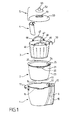
- the apparatus illustrated in FIGS. 1 to 8 is a cooker, in particular a pasta cooker, comprising a housing 1, a tank 2, a cooking basket 3, a sautéed accessory 4, and a lid 5.
- the housing 1 forms a housing 10 designed to receive the vessel 2.
- the upper edge of the housing 10 has notches 16 provided for receiving handles 20 of the vessel 2.
- the housing 1 has an upper lateral protuberance 17 housing a portion of the control members of the cooker.
- the upper lateral protuberance 17 extends from the upper edge of the housing 1.
- the lateral protuberance 17 also forms a gripping member.
- the housing 1 has a lateral protuberance 18 housing a raising and lowering device 6 of the cooking basket 3.
- the lateral protuberance 18 extends over the entire height of the housing 1.
- the housing 1 comprises a outer lower shell 11 and inner upper shell 12.
- the tank 2 comprises handles 20.
- the tank comprises a body 21 having a bottom 22 and a side wall 23.
- the body 21 of the tank 2 is for example made of coated aluminum.
- the handles 20 are mounted on the body 21.
- the vessel 2 is mounted in the housing 1. More particularly, the vessel 2 is removably mounted in the housing 1.
- the vessel 2 is associated with means 8.
- the heating means 8 are arranged in the tank 2.
- the tank 2 is provided to receive a cooking bath 40 visible in Figures 6 and 7.
- the cooking bath 40 placed in the tank 2 may be boiled by the heating means 8.
- the cooking basket 3 is arranged in the tank 2.
- the cooking basket 3 is associated with the raising and lowering device 6.
- the cooking basket 3 is mounted to move between a raised position, illustrated in FIG. 6, and a position lowered, illustrated in Figures 2 and 7.
- the cooking basket 3 is for example made of stainless steel.
- the cooking basket 3 has an upper peripheral edge 32 arranged inside the tank 2 when the cooking basket 3 is in the lowered position in the tank 2, as shown in Figure 2.
- the cooking basket 3 in position raised is arranged partially inside the tank 2, as shown in FIG.
- the cooking basket 3 has a perforated bottom 30.
- the cooking basket 3 has a perforated side wall 31.
- the perforated side wall 31 has side openings 38.
- the size of the side openings 38 increases from bottom to top of the cooking basket 3.
- the cooking basket 3 comprises a hooking member 39 provided to cooperate with the up and down device 6.
- the perforated bottom 30 has openings 34. Only a portion of the openings 34 has been shown in FIGS. 2, 6 and 7.
- the width of the openings 34 is preferably between 1 and 2 mm, to ensure a passage of sufficient steam, while preventing the passage of pasta such as spaghetti.
- the perforated bottom 30 has a peripheral zone 35 provided with openings 34. However, the peripheral zone 35 is not necessarily immediately adjacent to the perforated lateral wall 31.
- the peripheral zone 35 comprises, for example, an opening density 34 between and 20%.
- the peripheral zone 35 surrounds an intermediate zone 36 less dense in openings. More particularly, the intermediate zone 36 is devoid of openings.
- the intermediate zone 36 is raised in the direction of the peripheral zone 35.
- the perforated bottom 30 has a central zone 37 provided with openings 34.
- the central zone 37 also includes, for example, an opening density 34 of between 15 and 20%.
- the peripheral zone 35, the intermediate zone 36 and the central zone 37 are shown schematically in FIGS. 4 and 5.
- the perforated bottom 30 is curved downwards.
- the perforated bottom 30 has for example a radius d of the order of 80 cm.
- the cooking basket 3 comprises a peripheral wall 33 surrounding the perforated bottom 30.
- the cooking basket 3 in the lowered position in the tank 2 delimits with the tank 2 a boiling chamber 9 under the perforated bottom 30.
- the cooking basket 3 is based on the tank 2. More particularly, the cooking basket 3 rests on the bottom 22 of the tank 2.
- the peripheral wall 33 carries a seal 42 provided to bear against the tank 2.
- the seal 42 has a U-shaped section enclosing the peripheral wall 33.
- the seal 42 has a base 43 designed to rest on the bottom 22 of the tank 2.
- the seal 42 has an outer lip 44 provided to bear against the side wall 23 of the tank 2.
- the seal 42 allows to limit the leakage of steam between the tank 2 and the cooking basket 3.
- the seal 42 also avoids scratching the tank 2 with the cooking basket 3.
- the heating means 8 are arranged below the boiling chamber 9.
- the power of the heating means 8 is for example of the order of 2000 W. More particularly, the heating means 8 are arranged below the zone.
- the heating means 8 are formed by a shielded heating element 28 mounted under the bottom of the tank 2.
- the heating means 8 cooperate with a connector 29 arranged in the housing 1.
- the accessory sauces 4 is hooked on the upper peripheral edge 32 of the cooking basket 3, to allow heating or cooking sauces when cooking food placed in the cooking basket 3.
- the sauces accessory 4 can in particular be made of plastic.
- the cover 5 comprises a main body 50 having an upper opening 51 and a secondary body 52 provided with a gripping member 53, as best seen in FIG. 1.
- the secondary body 52 is removable and is intended to close the opening upper 51.
- the main body 50 and the secondary body 52 are for example made of stainless steel.
- the lid 5 is arranged on the cooking basket 3.
- the lid 5 covers the cooking basket 3.
- the lid 5 extends away from the peripheral edge upper 32 of the cooking basket 3. More particularly, the lid 5 rests on supports 46 from the cooking basket 3.
- the supports 46 form gripping means 47.
- the cover 5 has a bottom wall 54 having a peripheral portion inclined downwardly towards the periphery.
- the lid 5 has a lower peripheral edge 55 extending outside the cooking basket 3.
- the lower peripheral edge 55 is disposed at a distance h above the upper peripheral edge 32 of the cooking basket 3.
- the distance h is for example between 1 and 2 mm.
- the lower peripheral edge 55 is disposed at a distance r outside the upper peripheral edge 32 of the cooking basket 3.
- the distance r is for example between 2 and 5 mm.
- the lower peripheral edge 55 of the lid 5 goes down inside the tank 2 when the lid 5 is arranged on the cooking basket 3 in place in the bowl for cooking, as can be seen in FIG. 2.
- the cooking basket 3 is then in the lowered position in the tank 2.
- the lower peripheral edge 55 extends the bottom wall 54.
- the lid 5 arranged on the cooking basket 3 cleans a passage 56 with the cooking basket 3.
- the section of the passage 56 depends on the distance h and the distance r.
- the lid 5 arranged on the cooking basket 3 cleans an outside passage 57 with the tank 2 when the cooking basket 3 occupies the lowered position in the tank 2.
- the raising and lowering device 6 comprises a driving member 60 movable relative to the housing 1.
- the driving member 60 is mounted in a slideway 61 integral with the housing 1.
- the driving member 60 comprises a rack 62 driven by a motor 63.
- the hooking member 39 of the cooking basket 3 is removably mounted on the drive member 60.
- the drive member 60 activates a lower end-of-travel detector 64 when the lowering of the cooking basket 3, and an upper end-of-travel detector 65 during the ascent of the cooking basket 3.
- the lower end-of-travel detector 64 and the upper end-of-travel detector 65, visible in FIG. 6 are, for example, formed by switches.
- the cooker comprises a holding device 66 provided for blocking the cooking basket 3 in the lowered position in the tank 2 during cooking, in order to prevent the steam from escaping from the boiling chamber outside the openings 34. More particularly, the holding device 66 is formed by the raising and lowering device 6 of the cooking basket 3. The motor 63 blocks the rack 62 carried by the drive member 60. The forces exerted by the steam generated in the boiling chamber 9 exert a couple incompatible with the extraction of the attachment member 39 of the drive member 60. The cooking basket 3 is held in the lowered position on the bottom 22 of the tank 2. However the holding device 66 may have a certain elasticity so as to let steam escape between the cooking basket 3 and the tank 2 when the force exerted by the steam is too great.
- a vapor detection device 7 is provided to control the descent of the cooking basket 3 into the tank 2.
- the side wall 23 of the tank 2 has a vapor detection opening 24 arranged at the level of the cooking basket. 3 in a raised position, as visible in Figure 6.
- the section of the vapor detection opening 24 preferably corresponds to a diameter of between 10 and 20 mm.
- the side wall 23 has an internal conformation 25 overhanging the vapor detection opening 24.
- the internal conformation 25 preferably extends on either side of the vapor detection opening 24, and partially closes the space between the cooking basket 3 in the raised position and the tank 2.
- the vapor detection opening 24 communicates with a chamber 13.
- the vapor detection device 7 is capable of being activated by the steam flowing in the chamber 13 to control the descent of the cooking basket 3 into the tank 2.
- the chamber 13 is arranged in the housing 1.
- the chamber 13 opens into a side wall 14 of the housing 1 facing the vapor detection opening 24.
- the chamber 13 opens out of the cooker into an upper wall 15 of the housing 1.
- the side wall 14 and the top wall 15 belong to the inner upper shell 12 of the housing 1.
- the chamber 13 is formed by a duct 70.
- the vapor detection device 7 comprises a temperature sensor 77, visible in FIG. 8.
- the temperature sensor 77 is for example a resistance of type CTN.
- the temperature sensor 77 is arranged outside the duct 70.
- the temperature sensor 77 is mounted against a wall 71 of the duct 70.
- the wall 71 of the duct 70 is advantageously thinned at the temperature sensor 77.
- the duct 70 has a lateral end 72 arranged to be placed facing the vapor detection opening 24 of the tank 2 placed in the housing 1.
- the conduit 70 has an upper end 73 opening into an opening of the upper wall 15.
- the conduit 70 is ascending. More particularly, the duct 70 is oblique and bent upwards to facilitate the escape of the steam.
- the temperature sensor 77 is associated with a control device provided for supplying the motor 63 when the threshold temperature is detected in order to lower the cooking basket 3 in the lowered position.
- the controller also includes a user adjustable timer.
- the control device is provided to supply the motor 63 when the programmed time has elapsed, in order to raise the cooking basket 3 in the raised position.
- the operation of the cooker is as follows.
- the correct positioning of the tank 2 in the housing 1 is obtained by placing the handles 20 in the notches 16, possible only in the position for supplying the heating means 8 by the connector 29.
- the user fills the tank 2 of the desired amount of cooking bath, for example water with aromatics, and place the food to be cooked in the cooking basket 3 in the raised position.
- a proportion of 3 liters of water per 500 g of dry pasta may suffice, whereas the usual amount of water is 5 liters of water per 500 g of dry pasta.
- the user starts the cooker after selecting a cooking time.
- the heating means 8 carry the cooking bath 40 to boiling. Steam rises between the tank 2 and the cooking basket 3.
- the device vapor detection 7 detects the vapor circulating in the chamber 13 to control the descent of the cooking basket 3 into the tank 2.
- the heating device can continue to supply the heating means at full power and then feed the heating means 8 at reduced power.
- the steam produced in the boiling chamber 9, in particular during the heating at full power, makes it possible to stir the food during cooking.
- the food sticking on the perforated side wall 31 of the cooking basket 3 and the bonding of the alinients between them can thus be avoided.
- the heating at full power after the descent of the cooking basket 3 in the tank 2 makes it possible to soften more quickly the uncut spaghetti foot introduced by the upper opening 51 of the lid 5.
- the descent of the spaghetti in the cooking basket 3 is thus facilitated.
- the lid 5 avoids the projections of the cooking bath and limit the formation of foam, thanks to the lower peripheral edge 55 and the passage 56.
- the food is cooked for the duration indicated.
- the cooking basket 3 When the cooking time has elapsed, the cooking basket 3 is reassembled.
- the cooker allows automatic cooking. Cooking can be done without supervision.
- a warming phase can be provided, for example by alternating periods in which the cooking basket 3 is in the raised position and periods in which the cooking basket 3 is in the lowered position in the tank 2. If desired, the heating means 8 may be fed intermittently, in particular after the descent of the cooking basket 3 into the tank 2 and / or during the warm-up phase.
- the raising and lowering device 6 keeps the cooking basket 3 in the lowered position against the bottom 20 of the tank 2.
- the steam bubbles formed in the boiling chamber 9 are formed preferentially under the zone 35.
- the inclination of the intermediate zone 36 upward towards the periphery of the cooking basket 3 promotes the escape of the steam through the openings 34 of the peripheral zone 35 of the perforated bottom 30.
- the vapor rising along the perforated side wall 31 of the cooking basket 3 prevents the food sticking on said wall.
- Part of the steam escapes, however, through openings 34 of the central zone 37 and contributes to the stirring of the food in the cooking basket 3.
- the stirring of the food is particularly important during periods of heating at full power, because of the significant boiling in the boiling chamber 9.
- Stirring food such as pasta or noodles will prevent food sticking to each other and to the walls.
- the cooking of such foods is thus improved.
- the volume of cooking bath required for cooking can be reduced.
- the compactness of the device can be increased.
- Such a cooking basket 3 is particularly simple to build, use and clean.
- the cooking basket 3 arranged in the tank 2 may extend partially out of the tank 2, even in the lowered position.
- the holding device 66 of the cooking basket 3 is not necessarily formed by a device for raising and lowering the cooking basket.
- the holding device may comprise retaining elements disposed in the vessel and / or outside the vessel.
- the tank and the cooking basket may have a bayonet locking system, or a lid attached to the tank can hold the cooking basket in the tank.
- the peripheral wall 33 of the cooking basket 3 can rest directly on the tank 2.
- the cooking basket 3 does not necessarily rest on the bottom of the tank 2, but may in particular rest against the side wall of the tank 2 or against a shoulder of the tank 2.
- the peripheral wall 33 of the cooking basket 3 is not necessarily less, but may in particular be lateral.
- the tank 2 can be fixedly mounted in the housing 1.
- the cooker may be devoid of housing housing the tank 2.
- the cooker does not necessarily include means of heated.
- the cooking bath can then be brought to boiling by heating means not belonging to the cooker.
Abstract
Description
La présente invention concerne le domaine technique des cuiseurs comprenant un panier de cuisson agencé dans une cuve contenant un bain de cuisson susceptible d'être porté à ébullition.The present invention relates to the technical field of cookers comprising a cooking basket arranged in a tank containing a cooking bath that can be heated to boiling.
La présente invention concerne notamment les cuiseurs à pâtes. La présente invention concerne les ustensiles de cuisson placés sur une source de chauffe ainsi que les appareils de cuisson électrique comportant une source de chauffe.The present invention relates in particular to pasta cookers. The present invention relates to cooking utensils placed on a heating source as well as electric cooking appliances having a heating source.
Lors d'une cuisson dans un bain de cuisson, certains types d'aliments, tels que les pâtes, sont susceptibles de coller aux parois du réceptacle de cuisson. Notamment, lorsque le réceptacle de cuisson est un panier de cuisson ajouré placé dans une cuve contenant le bain de cuisson, l'agitation des aliments provoquée par l'ébullition du bain de cuisson est moindre que dans la cuve et le risque de collage des aliments aux parois du réceptacle de cuisson est augmenté.When cooking in a cooking bath, certain types of food, such as pasta, are likely to stick to the walls of the cooking receptacle. In particular, when the cooking receptacle is a perforated cooking basket placed in a tank containing the cooking bath, stirring of food caused by the boiling of the cooking bath is less than in the tank and the risk of sticking of food to the walls of the cooking receptacle is increased.
Il est connu du document
Un but de la présente invention est de proposer un cuiseur comportant un panier de cuisson agencé dans une cuve, dans lequel le risque de collage des aliments aux parois du panier de cuisson est limité.An object of the present invention is to provide a cooker having a cooking basket arranged in a tank, in which the risk of sticking food to the walls of the cooking basket is limited.
Un but de la présente invention est de proposer un cuiseur comportant un panier de cuisson agencé dans une cuve, dans lequel le risque de collage des aliments entre eux est limité.An object of the present invention is to provide a cooker comprising a cooking basket arranged in a tank, in which the risk of sticking of food between them is limited.
Un autre but de la présente invention est de proposer un cuiseur du type précité, dont la construction soit simple.Another object of the present invention is to provide a cooker of the aforementioned type, whose construction is simple.
Un autre but de la présente invention est de proposer un cuiseur du type précité, dont la construction soit compacte.Another object of the present invention is to provide a cooker of the aforementioned type, whose construction is compact.
Un autre but de la présente invention est de proposer un cuiseur du type précité, dont l'utilisation soit simple.Another object of the present invention is to provide a cooker of the aforementioned type, the use of which is simple.
Un autre but de la présente invention est de proposer un cuiseur du type précité, dont l'utilisation soit économique.Another object of the present invention is to provide a cooker of the aforementioned type, the use of which is economical.
Un autre but de la présente invention est de proposer un cuiseur du type précité, dont le nettoyage du panier de cuisson soit aisé.Another object of the present invention is to provide a cooker of the aforementioned type, the cleaning of the cooking basket is easy.
Un autre but de la présente invention est de proposer un cuiseur du type précité, dont le nettoyage de la cuve soit aisé.Another object of the present invention is to provide a cooker of the aforementioned type, the cleaning of the tank is easy.
Un autre but de la présente invention est de proposer un cuiseur du type précité permettant une cuisson sans surveillance.Another object of the present invention is to provide a cooker of the aforementioned type for unattended cooking.
Ces buts sont atteints avec un cuiseur, notamment un cuiseur à pâtes, comportant une cuve prévue pour recevoir un bain de cuisson susceptible d'être porté à ébullition, un panier de cuisson agencé dans la cuve, le panier de cuisson présentant un fond ajouré, le panier de cuisson délimitant avec la cuve une chambre d'ébullition sous le fond ajouré, le fond ajouré présentant une zone périphérique pourvue d'ouvertures, du fait que la zone périphérique entoure une zone intermédiaire moins dense en ouvertures. Cette disposition permet de forcer la vapeur à passer préférentiellement par le fond ajouré pour s'échapper. Cette disposition contribue à favoriser l'agitation du bain de cuisson dans le panier de cuisson. Les risques de collage des aliments contre les parois du bain de cuisson ou entre eux sont ainsi diminués. Cette disposition permet de favoriser l'échappement des bulles de vapeur le long de la paroi latérale du panier de cuisson, permettant ainsi de contrarier le collage des aliments sur ladite paroi latérale. La construction d'un tel cuiseur reste simple. L'utilisateur n'a pas besoin de remuer les aliments, la cuisson peut être effectuée sans surveillance. Du fait de l'absence de pale entraînée en rotation dans le panier de cuisson, l'utilisation de l'appareil et le nettoyage de la cuve et du panier de cuisson sont facilités. Le remuage obtenu permet de réduire la quantité d'eau nécessaire à la cuisson, ce qui permet de diminuer la hauteur de la cuve ainsi que la quantité d'énergie nécessaire à la cuisson.These goals are achieved with a cooker, including a pasta cooker, having a tank adapted to receive a cooking bath that can be brought to a boil, a cooking basket arranged in the tank, the cooking basket having a perforated bottom, the cooking basket delimiting with the tank a boiling chamber under the perforated bottom, the perforated bottom having a peripheral zone provided with openings, because the peripheral zone surrounds a less dense intermediate zone openings. This arrangement makes it possible to force the steam to pass preferentially through the perforated bottom to escape. This arrangement helps to promote the stirring of the cooking bath in the cooking basket. The risk of sticking food against the walls of the cooking bath or between them are thus reduced. This arrangement makes it possible to encourage the escape of the vapor bubbles along the side wall of the cooking basket, thus making it possible to thwart the bonding of the food on said side wall. The construction of such a cooker remains simple. The user does not need to stir food, cooking can be done unattended. Due to the absence of blades rotated in the cooking basket, the use of the apparatus and the cleaning of the tank and the cooking basket are facilitated. The riddling obtained reduces the amount of water required for cooking, which reduces the height of the tank and the amount of energy required for cooking.
Avantageusement, le cuiseur comporte un dispositif de maintien prévu pour bloquer le panier de cuisson dans la cuve lors de la cuisson. Cette disposition permet d'éviter que l'ébullition ne soulève le panier de cuisson lors de la cuisson, l'efficacité du remuage des aliments étant fortement limitée si la vapeur peut passer ailleurs que par le fond ajouré.Advantageously, the cooker comprises a holding device provided for blocking the cooking basket in the tank during cooking. This arrangement makes it possible to prevent boiling from raising the cooking basket during cooking, since the efficiency of stirring of food is greatly limited if the steam can pass away from the perforated bottom.
Selon une construction avantageuse, le dispositif de maintien est formé par un dispositif de monte et baisse du panier de cuisson.According to an advantageous construction, the holding device is formed by a device for raising and lowering the cooking basket.
Avantageusement, le panier de cuisson comporte une paroi périphérique entourant le fond ajouré. Cette disposition permet de simplifier la construction de la cuve.Advantageously, the cooking basket comprises a peripheral wall surrounding the perforated bottom. This arrangement simplifies the construction of the tank.
Avantageusement alors, la paroi périphérique porte un joint prévu pour prendre appui contre la cuve. Cette disposition permet de limiter les fuites de vapeur de la chambre d'ébullition. En alternative la paroi périphérique peut reposer sur la cuve. De préférence alors la paroi périphérique repose sur le fond de la cuve. Le fond de la cuve peut ainsi être dépourvu de conformation prévue spécifiquement pour la réception du panier de cuisson.Advantageously then, the peripheral wall carries a seal provided to bear against the tank. This arrangement makes it possible to limit the steam leakage from the boiling chamber. Alternatively the peripheral wall can rest on the tank. Preferably then the peripheral wall rests on the bottom of the tank. The bottom of the tank may thus be devoid of conformation provided specifically for the reception of the cooking basket.
Avantageusement alors, la zone intermédiaire est dépourvue d'ouvertures. Avantageusement alors la zone intermédiaire est relevée en direction de la zone périphérique. Ces dispositions contribuent à diriger la vapeur vers la zone périphérique.Advantageously then, the intermediate zone is devoid of openings. Advantageously then the intermediate zone is raised in the direction of the peripheral zone. These provisions help to direct the steam towards the peripheral zone.
Avantageusement encore le fond ajouré présente une zone centrale pourvue d'ouvertures. Cette disposition permet d'agiter également la partie centrale du bain de cuisson dans le panier de cuisson.Advantageously, the perforated bottom has a central zone provided with openings. This arrangement also makes it possible to shake the central part of the cooking bath in the cooking basket.
Avantageusement encore le fond ajouré est bombé vers le bas. Cette disposition contribue à diriger les bulles de vapeur vers la périphérie.Advantageously, the perforated bottom is curved downwards. This arrangement helps to direct the vapor bubbles towards the periphery.
Avantageusement encore le panier de cuisson comporte une paroi latérale perforée, pour faciliter l'égouttage des aliments et diminuer les risques de moussage et de débordement.Advantageously still the cooking basket has a perforated side wall, to facilitate the draining of food and reduce the risk of foaming and overflow.
Selon une forme de réalisation avantageuse, la cuve est montée dans un boîtier.According to an advantageous embodiment, the tank is mounted in a housing.
Avantageusement encore la cuve est montée amovible dans le boîtier. Cette disposition permet notamment de faciliter le nettoyage de la cuve.Advantageously, the tank is removably mounted in the housing. This arrangement makes it possible in particular to facilitate the cleaning of the tank.
Selon une forme de réalisation avantageuse la cuve est associée à des moyens de chauffe. Par exemple les moyens de chauffe peuvent être solidaires de la cuve ou encore être montés dans le boîtier. En alternative la cuve peut être dépourvue de moyens de chauffe et être prévue pour être placée sur une source chauffante.According to an advantageous embodiment, the tank is associated with heating means. For example the heating means may be integral with the tank or be mounted in the housing. Alternatively the tank may be devoid of heating means and be provided to be placed on a heating source.
L'invention sera mieux comprise à l'étude d'un exemple de réalisation, pris à titre nullement limitatif, illustré dans les figures annexées, dans lesquelles :
- la figure 1 est une vue schématique en éclaté d'un exemple de réalisation d'un cuiseur selon l'invention,
- la figure 2 est une vue de côté en coupe du cuiseur illustré à la figure 1,
- la figure 3 est une vue en perspective du boîtier et de la cuve du cuiseur illustré aux figures 1 et 2, le panier de cuisson, le couvercle et l'accessoire à sauces ayant été retirés,
- la figure 4 est une vue en perspective de dessus du panier de cuisson visible aux figures 1 et 2,
- la figure 5 est une vue en perspective de dessous du panier de cuisson visible aux figures 1 et 2,
- la figure 6 est une vue en perspective et en coupe du cuiseur illustré aux figures 1 et 2, le panier de cuisson étant en position relevée,
- la figure 7 est une vue en perspective et en coupe du cuiseur illustré aux figures .1, 2 et 6, le panier de cuisson étant en position abaissée,
- la figure 8 est une vue d'une partie du dispositif de détection de vapeur.
- FIG. 1 is a schematic exploded view of an exemplary embodiment of a cooker according to the invention,
- FIG. 2 is a sectional side view of the cooker illustrated in FIG.
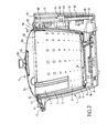
- Figure 3 is a perspective view of the housing and the tank of the cooker illustrated in Figures 1 and 2, the cooking basket, the lid and the sautéed accessory having been removed,
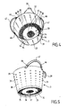
- FIG. 4 is a perspective view from above of the cooking basket visible in FIGS. 1 and 2,
- FIG. 5 is a bottom perspective view of the cooking basket visible in FIGS. 1 and 2,
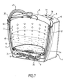
- Figure 6 is a perspective view in section of the cooker illustrated in Figures 1 and 2, the cooking basket being in the raised position,
- FIG. 7 is a perspective view in section of the cooker illustrated in FIGS. 1, 2 and 6, the cooking basket being in the lowered position,
- Figure 8 is a view of a portion of the vapor detection device.
L'appareil illustré aux figures 1 à 8 est un cuiseur, notamment un cuiseur à pâtes, comportant un boîtier 1, une cuve 2, un panier de cuisson 3, un accessoire à sauces 4, et un couvercle 5.The apparatus illustrated in FIGS. 1 to 8 is a cooker, in particular a pasta cooker, comprising a
Tel que visible sur la figure 1, le boîtier 1 forme un logement 10 prévu pour recevoir la cuve 2. Le bord supérieur du logement 10 présente des échancrures 16 prévues pour recevoir des poignées 20 de la cuve 2.As can be seen in FIG. 1, the
Le boîtier 1 présente une protubérance latérale supérieure 17 logeant une partie des organes de commande du cuiseur. La protubérance latérale supérieure 17 s'étend à partir du bord supérieur du boîtier 1. La protubérance latérale 17 forme également un organe de préhension. Le boîtier 1 présente une protubérance latérale 18 logeant un dispositif de monte et baisse 6 du panier de cuisson 3. La protubérance latérale 18 s'étend sur toute la hauteur du boîtier 1. Tel que visible sur la figure 2, le boîtier 1 comporte une coque inférieure extérieure 11 et une coque supérieure intérieure 12.The
La cuve 2 comporte des poignées 20. La cuve comporte un corps 21 présentant un fond 22 et une paroi latérale 23. Le corps 21 de la cuve 2 est par exemple réalisé en aluminium revêtu. Les poignées 20 sont montées sur le corps 21. Tel que montré à la figure 3, la cuve 2 est montée dans le boîtier 1. Plus particulièrement, la cuve 2 est montée amovible dans le boîtier 1. La cuve 2 est associée à des moyens de chauffe 8. Tel que montré à la figure 2, les moyens de chauffe 8 sont agencés sous la cuve 2. La cuve 2 est prévue pour recevoir un bain de cuisson 40 visible sur les figures 6 et 7. Le bain de cuisson 40 placé dans la cuve 2 est susceptible d'être porté à ébullition par les moyens de chauffe 8.The
Le panier de cuisson 3 est agencé dans la cuve 2. Le panier de cuisson 3 est associé au dispositif de monte et baisse 6. Le panier de cuisson 3 est monté mobile entre une position relevée, illustrée à la figure 6, et une position abaissée, illustrée aux figures 2 et 7. Le panier de cuisson 3 est par exemple réalisé en acier inoxydable.The
Le panier de cuisson 3 présente un bord périphérique supérieur 32 agencé à l'intérieur de la cuve 2 lorsque le panier de cuisson 3 est en position abaissée dans la cuve 2, tel que montré à la figure 2. Le panier de cuisson 3 en position relevée est agencé partiellement à l'intérieur de la cuve 2, tel que montré à la figure 6.The
Tel que mieux visible aux figures 4 et 5, le panier de cuisson 3 présente un fond ajouré 30. Le panier de cuisson 3 comporte une paroi latérale perforée 31. La paroi latérale perforée 31 présente des ouvertures latérales 38. La taille des ouvertures latérales 38 augmente du bas vers le haut du panier de cuisson 3. Le panier de cuisson 3 comporte un organe d'accrochage 39 prévu pour coopérer avec le dispositif de monte et baisse 6.As best seen in Figures 4 and 5, the
Plus particulièrement, le fond ajouré 30 comporte des ouvertures 34. Seule une partie des ouvertures 34 a été représentée sur les figures 2, 6 et 7. La largeur des ouvertures 34 est de préférence comprise entre 1 et 2 mm, pour assurer un passage de vapeur suffisant, tout en empêchant le passage de pâtes telles que les spaghetti. Le fond ajouré 30 présente une zone périphérique 35 pourvue d'ouvertures 34. La zone périphérique 35 n'est toutefois pas nécessairement immédiatement adjacente à la paroi latérale perforée 31. La zone périphérique 35 comporte par exemple une densité d'ouvertures 34 comprise entre 15 et 20%. La zone périphérique 35 entoure une zone intermédiaire 36 moins dense en ouvertures. Plus particulièrement la zone intermédiaire 36 est dépourvue d'ouvertures. La zone intermédiaire 36 est relevée en direction de la zone périphérique 35. Le fond ajouré 30 présente une zone centrale 37 pourvue d'ouvertures 34. La zone centrale 37 comporte par exemple aussi une densité d'ouvertures 34 comprise entre 15 et 20%. La zone périphérique 35, la zone intermédiaire 36 et la zone centrale 37 sont représentées schématiquement sur les figures 4 et 5.More particularly, the perforated bottom 30 has
Tel que mieux visible sur la figure 2, le fond ajouré 30 est bombé vers le bas.As best seen in Figure 2, the perforated bottom 30 is curved downwards.
Le fond ajouré 30 présente par exemple un rayon d de l'ordre de 80 cm. Le panier de cuisson 3 comporte une paroi périphérique 33 entourant le fond ajouré 30. Le panier de cuisson 3 en position abaissée dans la cuve 2 délimite avec la cuve 2 une chambre d'ébullition 9 sous le fond ajouré 30. Le panier de cuisson 3 repose sur la cuve 2. Plus particulièrement, le panier de cuisson 3 repose sur le fond 22 de la cuve 2. La paroi périphérique 33 porte un joint 42 prévu pour prendre appui contre la cuve 2. Le joint 42 présente une section en U enserrant la paroi périphérique 33. Le joint 42 présente une base 43 prévue pour reposer sur le fond 22 de la cuve 2. Le joint 42 présente une lèvre externe 44 prévue pour prendre appui contre la paroi latérale 23 de la cuve 2. Le joint 42 permet de limiter les fuites de vapeur entre la cuve 2 et le panier de cuisson 3. Le joint 42 permet aussi d'éviter de rayer la cuve 2 avec le panier de cuisson 3.The perforated bottom 30 has for example a radius d of the order of 80 cm. The
Les moyens de chauffe 8 sont agencés en dessous de la chambre d'ébullition 9. La puissance des moyens de chauffe 8 est par exemple de l'ordre de 2000 W. Plus particulièrement, les moyens de chauffe 8 sont agencés en dessous de la zone périphérique 35. Les moyens de chauffe 8 sont formés par un élément chauffant blindé 28 rapporté sous le fond de la cuve 2. Les moyens de chauffe 8 coopèrent avec un connecteur 29 agencé dans le boîtier 1.The heating means 8 are arranged below the boiling
L'accessoire à sauces 4 est accroché sur le bord périphérique supérieur 32 du panier de cuisson 3, pour permettre le réchauffage voire la cuisson de sauces lors de la cuisson des aliments placés dans le panier de cuisson 3. L'accessoire à sauces 4 peut notamment être réalisé en matière plastique.The
Le couvercle 5 comporte un corps principal 50 présentant une ouverture supérieure 51 et un corps secondaire 52 muni d'un organe de préhension 53, tel que mieux visible sur la figure 1. Le corps secondaire 52 est amovible et est prévu pour fermer l'ouverture supérieure 51. Le corps principal 50 et le corps secondaire 52 sont par exemple réalisés en acier inoxydable.The
Le couvercle 5 est agencé sur le panier de cuisson 3. Le couvercle 5 couvre le panier de cuisson 3. Le couvercle 5 s'étend à distance du bord périphérique supérieur 32 du panier de cuisson 3. Plus particulièrement, le couvercle 5 repose sur des supports 46 issus du panier de cuisson 3. Les supports 46 forment des moyens de préhension 47.The
Le couvercle 5 présente une paroi inférieure 54 ayant une partie périphérique inclinée vers le bas en direction de la périphérie. Le couvercle 5 comporte un bord périphérique inférieur 55 s'étendant à l'extérieur du panier de cuisson 3. Le bord périphérique inférieur 55 est disposé à une distance h au dessus du bord périphérique supérieur 32 du panier de cuisson 3. La distance h est par exemple comprise entre 1 et 2 mm. Le bord périphérique inférieur 55 est disposé à une distance r à l'extérieur du bord périphérique supérieur 32 du panier de cuisson 3. La distance r est par exemple comprise entre 2 et 5 mm. Le bord périphérique inférieur 55 du couvercle 5 descend à l'intérieur de la cuve 2 lorsque le couvercle 5 est agencé sur le panier de cuisson 3 en place dans la cuve pour la cuisson, tel que visible sur la figure 2. Le panier de cuisson 3 est alors en position abaissée dans la cuve 2. Le bord périphérique inférieur 55 prolonge la paroi inférieure 54.The
Le couvercle 5 agencé sur le panier de cuisson 3 ménage un passage 56 avec le panier de cuisson 3. La section du passage 56 dépend de la distance h et de la distance r. Le couvercle 5 agencé sur le panier de cuisson 3 ménage un passage extérieur 57 avec la cuve 2 lorsque le panier de cuisson 3 occupe la position abaissée dans la cuve 2.The
Le dispositif de monte et baisse 6 comporte un organe d'entraînement 60 mobile par rapport au boîtier 1. L'organe d'entraînement 60 est monté dans une glissière 61 solidaire du boîtier 1. L'organe d'entraînement 60 comporte une crémaillère 62 entraînée par un moteur 63. L'organe d'accrochage 39 du panier de cuisson 3 est monté de manière amovible sur l'organe d'entraînement 60. L'organe d'entraînement 60 active un détecteur de fin de course inférieur 64 lors de la descente du panier de cuisson 3, et un détecteur de fin de course supérieur 65 lors de la remontée du panier de cuisson 3. Le détecteur de fin de course inférieur 64 et le détecteur de fin de course supérieur 65, visibles sur la figure 6, sont par exemple formés par des interrupteurs.The raising and lowering
Le cuiseur comporte un dispositif de maintien 66 prévu pour bloquer le panier de cuisson 3 en position abaissée dans la cuve 2 lors de la cuisson, afin d'éviter que la vapeur s'échappe de la chambre d'ébullition en dehors des ouvertures 34. Plus particulièrement, le dispositif de maintien 66 est formé par le dispositif de monte et baisse 6 du panier de cuisson 3. Le moteur 63 bloque la crémaillère 62 portée par l'organe d'entraînement 60. Les efforts exercés par la vapeur générée dans la chambre d'ébullition 9 exercent un couple incompatible avec l'extraction de l'organe d'accrochage 39 de l'organe d'entraînement 60. Le panier de cuisson 3 est maintenu en position abaissée sur le fond 22 de la cuve 2. Toutefois le dispositif de maintien 66 peut présenter une certaine élasticité de manière à laisser échapper de la vapeur entre le panier de cuisson 3 et la cuve 2 lorsque l'effort exercé par la vapeur est trop important.The cooker comprises a holding
Un dispositif de détection de vapeur 7 est prévu pour commander la descente du panier de cuisson 3 dans la cuve 2. A cet effet, la paroi latérale 23 de la cuve 2 présente une ouverture de détection de vapeur 24 agencée au niveau du panier de cuisson 3 occupant une position relevée, tel que visible sur la figure 6. La section de l'ouverture de détection de vapeur 24 correspond de préférence à un diamètre compris entre 10 et 20 mm. La paroi latérale 23 comporte une conformation interne 25 surplombant l'ouverture de détection de vapeur 24. La conformation interne 25 s'étend de préférence de part et d'autre de l'ouverture de détection de vapeur 24, et obture partiellement l'espace compris entre le panier de cuisson 3 en position relevée et la cuve 2. L'ouverture de détection de vapeur 24 communique avec une chambre 13. Le dispositif de détection de vapeur 7 est susceptible d'être activé par la vapeur circulant dans la chambre 13 pour commander la descente du panier de cuisson 3 dans la cuve 2. La chambre 13 est agencée dans le boîtier 1. La chambre 13 débouche dans une paroi latérale 14 du boîtier 1 en regard de l'ouverture de détection de vapeur 24. La chambre 13 débouche à l'extérieur du cuiseur, dans une paroi supérieure 15 du boîtier 1. La paroi latérale 14 et la paroi supérieure 15 appartiennent à la coque supérieure intérieure 12 du boîtier 1.A
Tel que visible aux figures 6 et 8, la chambre 13 est formée par un conduit 70. Le dispositif de détection de vapeur 7 comporte un capteur de température 77, visible sur la figure 8. Le capteur de température 77 est par exemple une résistance de type CTN. Le capteur de température 77 est agencé à l'extérieur du conduit 70. Le capteur de température 77 est monté contre une paroi 71 du conduit 70. La paroi 71 du conduit 70 est avantageusement amincie au niveau du capteur de température 77. Le conduit 70 présente une extrémité latérale 72 prévue pour être placée en regard de l'ouverture de détection de vapeur 24 de la cuve 2 placée dans le boîtier 1. Le conduit 70 présente une extrémité supérieure 73 débouchant dans une ouverture de la paroi supérieure 15. Le conduit 70 est ascendant. Plus particulièrement, le conduit 70 est oblique et coudé vers le haut, pour faciliter l'échappement de la vapeur.As can be seen in FIGS. 6 and 8, the
Le capteur de température 77 est associé à un dispositif de commande prévu pour alimenter le moteur 63 lorsque la température seuil est détectée afin de descendre le panier de cuisson 3 en position abaissée. Le dispositif de commande comporte également un minuteur réglable par l'utilisateur. Le dispositif de commande est prévu pour alimenter le moteur 63 lorsque le temps programmé est écoulé, afin de remonter le panier de cuisson 3 en position relevée.The
Le fonctionnement du cuiseur est le suivant.The operation of the cooker is as follows.
Le positionnement correct de la cuve 2 dans le boîtier 1 est obtenu par la mise en place des poignées 20 dans les échancrures 16, possible seulement dans la position permettant l'alimentation des moyens de chauffe 8 par le connecteur 29. L'utilisateur remplit la cuve 2 de la quantité de bain de cuisson souhaitée, par exemple de l'eau avec des aromates, et place les aliments à cuire dans le panier de cuisson 3 en position relevée. Pour la cuisson de pâtes, une proportion de 3 litres d'eau pour 500 g de pâtes sèches peut suffire, alors que la quantité d'eau usuelle est de 5 litres d'eau pour 500 g de pâtes sèches. L'utilisateur met en marche le cuiseur après avoir sélectionné une durée de cuisson. Les moyens de chauffe 8 portent le bain de cuisson 40 à ébullition. De la vapeur monte entre la cuve 2 et le panier de cuisson 3. Le dispositif de détection de vapeur 7 détecte la vapeur circulant dans la chambre 13 pour commander la descente du panier de cuisson 3 dans la cuve 2. Si désiré, le dispositif de chauffe peut continuer à alimenter les moyens de chauffe à pleine puissance puis alimenter les moyens de chauffe 8 à puissance réduite. La vapeur produite dans la chambre d'ébullition 9, notamment lors de la chauffe à pleine puissance, permet d'agiter les aliments pendant la cuisson. Le collage des aliments sur la paroi latérale ajourée 31 du panier de cuisson 3 et le collage des alinients entre eux peut ainsi être évité. Le chauffage à pleine puissance après la descente du panier de cuisson 3 dans la cuve 2 permet de ramollir plus rapidement le pied de spaghetti non coupés introduits par l'ouverture supérieure 51 du couvercle 5. La descente des spaghetti dans le panier de cuisson 3 est ainsi facilitée. Le couvercle 5 permet d'éviter les projections du bain de cuisson et de limiter la formation de mousse, grâce au bord périphérique inférieur 55 et au passage 56. Les aliments sont cuits pendant la durée indiquée. Lorsque la durée de cuisson est écoulée, le panier de cuisson 3 est remonté. Le cuiseur permet une cuisson automatique. La cuisson peut être effectuée sans surveillance. Une phase de maintien au chaud peut être prévue, par exemple en alternant des périodes dans lesquelles le panier de cuisson 3 est en position relevée et des périodes dans lesquelles le panier de cuisson 3 est en position abaissée dans la cuve 2. Si désiré, les moyens de chauffe 8 peuvent être alimentés par intermittence, notamment après la descente du panier de cuisson 3 dans la cuve 2 et/ou pendant la phase de maintien au chaud.The correct positioning of the
Plus particulièrement selon l'invention, le dispositif de monte et baisse 6 maintient le panier de cuisson 3 en position abaissée contre le fond 20 de la cuve 2. Les bulles de vapeur formées dans la chambre d'ébullition 9 sont formées préférentiellement sous la zone périphérique 35. L'inclinaison de la zone intermédiaire 36 vers le haut en direction de la périphérie du panier de cuisson 3 favorise l'échappement de la vapeur par les ouvertures 34 de la zone périphérique 35 du fond ajouré 30. La vapeur remontant le long de la paroi latérale perforée 31 du panier de cuisson 3 permet d'éviter le collage des aliments sur ladite paroi. Une partie de la vapeur s'échappe toutefois par les ouvertures 34 de la zone centrale 37 et contribue au remuage des aliments dans le panier de cuisson 3. L'agitation des aliments est particulièrement importante pendant les périodes de chauffe à pleine puissance, du fait de l'ébullition importante dans la chambre d'ébullition 9. L'agitation d'aliments tels que des pâtes ou des nouilles permet d'éviter le collage des aliments entre eux et sur les parois. La cuisson de tels aliments est ainsi améliorée. Le volume de bain de cuisson nécessaire pour la cuisson peut être réduit. La compacité de l'appareil peut être augmentée. Un tel panier de cuisson 3 est particulièrement simple à construire, à utiliser et à nettoyer.More particularly according to the invention, the raising and lowering
A titre de variante, le panier de cuisson 3 agencé dans la cuve 2 peut s'étendre partiellement hors de la cuve 2, même dans la position abaissée.Alternatively, the
A titre de variante, le dispositif de maintien 66 du panier de cuisson 3 n'est pas nécessairement formé par un dispositif de monte et baisse du panier de cuisson. Le dispositif de maintien peut comporter des éléments de retenue disposés dans la cuve et/ou à l'extérieur de la cuve. Par exemple la cuve et le panier de cuisson peuvent présenter un système de verrouillage à baïonnette, ou encore un couvercle accroché sur la cuve peut maintenir le panier de cuisson dans la cuve.Alternatively, the holding
A titre de variante, la paroi périphérique 33 du panier de cuisson 3 peut reposer directement sur la cuve 2.As a variant, the
A titre de variante, le panier de cuisson 3 ne repose pas nécessairement sur le fond de la cuve 2, mais peut notamment reposer contre la paroi latérale de la cuve 2 ou contre un épaulement de la cuve 2.As a variant, the
A titre de variante, la paroi périphérique 33 du panier de cuisson 3 n'est pas nécessairement inférieure, mais peut notamment être latérale.As a variant, the
A titre de variante, la cuve 2 peut être montée fixe dans le boîtier 1.Alternatively, the
A titre de variante, le cuiseur peut être dépourvu de boîtier logeant la cuve 2.Alternatively, the cooker may be devoid of housing housing the
A titre de variante, le cuiseur ne comporte pas nécessairement des moyens de chauffe. Le bain de cuisson peut alors être porté à ébullition par des moyens de chauffe n'appartenant pas au cuiseur.Alternatively, the cooker does not necessarily include means of heated. The cooking bath can then be brought to boiling by heating means not belonging to the cooker.
La présente invention n'est nullement limitée à l'exemple de réalisation décrit et à ses variantes, mais englobe de nombreuses modifications dans le cadre des revendications.The present invention is not limited to the embodiment described and its variants, but encompasses many modifications within the scope of the claims.
Claims (13)
Applications Claiming Priority (1)
| Application Number | Priority Date | Filing Date | Title |
|---|---|---|---|
| FR0506332A FR2887419A1 (en) | 2005-06-22 | 2005-06-22 | COOKTOP COOKER HAVING A FOOD RECOVERY SYSTEM |
Publications (1)
| Publication Number | Publication Date |
|---|---|
| EP1736084A1 true EP1736084A1 (en) | 2006-12-27 |
Family
ID=35828766
Family Applications (1)
| Application Number | Title | Priority Date | Filing Date |
|---|---|---|---|
| EP06356069A Withdrawn EP1736084A1 (en) | 2005-06-22 | 2006-06-16 | Cooker with food stirring device |
Country Status (3)
| Country | Link |
|---|---|
| EP (1) | EP1736084A1 (en) |
| CN (1) | CN1883348A (en) |
| FR (1) | FR2887419A1 (en) |
Cited By (5)
| Publication number | Priority date | Publication date | Assignee | Title |
|---|---|---|---|---|
| GB2443478A (en) * | 2006-10-31 | 2008-05-07 | Jeffrey Richard Hewitt | Spaghetti cooking aid |
| CN102406453A (en) * | 2011-11-30 | 2012-04-11 | 刘普东 | Nonstick basket |
| CN108903698A (en) * | 2018-10-11 | 2018-11-30 | 广东久和电气实业有限公司 | Diatery supplement blender |
| EP3491979A1 (en) * | 2017-11-29 | 2019-06-05 | LAGOSTINA S.p.A. | Cooking vessel, in particular for pasta |
| WO2023036503A1 (en) * | 2021-09-13 | 2023-03-16 | Simon Best | Electric water heater for heating and cooking foods |
Families Citing this family (4)
| Publication number | Priority date | Publication date | Assignee | Title |
|---|---|---|---|---|
| CN104274061B (en) * | 2013-07-02 | 2017-09-19 | 美的集团股份有限公司 | Electric cooker and its interior pot |
| CN107296070A (en) * | 2016-04-14 | 2017-10-27 | 党磊 | A kind of machinery of automatic boiled noodle |
| WO2018079462A1 (en) * | 2016-10-28 | 2018-05-03 | パナソニックIpマネジメント株式会社 | Cooking device |
| CN110464204A (en) * | 2019-07-26 | 2019-11-19 | 深圳爱她他智能餐饮技术有限公司 | A kind of overturning face basket, system of washing one's face and method of washing one's face |
Citations (6)
| Publication number | Priority date | Publication date | Assignee | Title |
|---|---|---|---|---|
| US875972A (en) * | 1906-05-24 | 1908-01-07 | Vertriebscentrale Fuer Haushaltsartikel Triebert & Wessel G M B H | Vessel for cooking and like purposes. |
| US4951558A (en) * | 1989-04-03 | 1990-08-28 | Figliuzzi Vincent D | Basket lifting mechanism for cooking pot |
| US5937741A (en) * | 1997-12-17 | 1999-08-17 | Manger; William M. | Automatic pasta preparer |
| US6055901A (en) * | 1998-09-17 | 2000-05-02 | Amway Corporation | Cooking utensil |
| US20030192435A1 (en) * | 2002-04-11 | 2003-10-16 | Mcnair John Duncan | Cooking appliance |
| WO2004002280A1 (en) | 2002-06-28 | 2004-01-08 | De' Longhi S.P.A. | Cooking device and procedure |
-
2005
- 2005-06-22 FR FR0506332A patent/FR2887419A1/en not_active Withdrawn
-
2006
- 2006-06-16 EP EP06356069A patent/EP1736084A1/en not_active Withdrawn
- 2006-06-21 CN CNA2006100869703A patent/CN1883348A/en active Pending
Patent Citations (6)
| Publication number | Priority date | Publication date | Assignee | Title |
|---|---|---|---|---|
| US875972A (en) * | 1906-05-24 | 1908-01-07 | Vertriebscentrale Fuer Haushaltsartikel Triebert & Wessel G M B H | Vessel for cooking and like purposes. |
| US4951558A (en) * | 1989-04-03 | 1990-08-28 | Figliuzzi Vincent D | Basket lifting mechanism for cooking pot |
| US5937741A (en) * | 1997-12-17 | 1999-08-17 | Manger; William M. | Automatic pasta preparer |
| US6055901A (en) * | 1998-09-17 | 2000-05-02 | Amway Corporation | Cooking utensil |
| US20030192435A1 (en) * | 2002-04-11 | 2003-10-16 | Mcnair John Duncan | Cooking appliance |
| WO2004002280A1 (en) | 2002-06-28 | 2004-01-08 | De' Longhi S.P.A. | Cooking device and procedure |
Cited By (7)
| Publication number | Priority date | Publication date | Assignee | Title |
|---|---|---|---|---|
| GB2443478A (en) * | 2006-10-31 | 2008-05-07 | Jeffrey Richard Hewitt | Spaghetti cooking aid |
| GB2443478B (en) * | 2006-10-31 | 2009-03-18 | Jeffrey Richard Hewitt | Spaghetti cooking aid |
| CN102406453A (en) * | 2011-11-30 | 2012-04-11 | 刘普东 | Nonstick basket |
| EP3491979A1 (en) * | 2017-11-29 | 2019-06-05 | LAGOSTINA S.p.A. | Cooking vessel, in particular for pasta |
| CN108903698A (en) * | 2018-10-11 | 2018-11-30 | 广东久和电气实业有限公司 | Diatery supplement blender |
| CN108903698B (en) * | 2018-10-11 | 2023-12-26 | 广东久和电气实业有限公司 | Supplementary food mixer |
| WO2023036503A1 (en) * | 2021-09-13 | 2023-03-16 | Simon Best | Electric water heater for heating and cooking foods |
Also Published As
| Publication number | Publication date |
|---|---|
| FR2887419A1 (en) | 2006-12-29 |
| CN1883348A (en) | 2006-12-27 |
Similar Documents
| Publication | Publication Date | Title |
|---|---|---|
| EP1736084A1 (en) | Cooker with food stirring device | |
| EP1736085B1 (en) | Pasta cooker with movable basket, comprising a boiling sensor | |
| EP1057437B1 (en) | Multifunctional culinary apparatus | |
| EP1922967B1 (en) | Heating kitchen appliance comprising an intermediate cooking container | |
| EP3087879B1 (en) | Steam-cooking accessory comprising a pan for recovering condensates intended for resting on a mixing bowl of a household appliance | |
| EP2339948A1 (en) | Device for preparing and cooking food and associated household electrical appliance | |
| EP2731482B1 (en) | Kitchenware item provided with a handle that electrically cooperates with a removable accessory | |
| EP1815773A1 (en) | Heating base with quick steam production and simplified use for a steam cooker | |
| WO2002051289A1 (en) | Utensil for slow-cook cycle steaming | |
| EP2574258A1 (en) | Heating household apparatus, in particular for preparing sauces | |
| EP3424378A1 (en) | Internal receptacle, food preparation accessory and kitchen appliance including such an internal receptacle | |
| EP1736083A1 (en) | Cooker with anti-foaming device | |
| FR2846217A1 (en) | STEAM PRODUCTION BASE FOR STEAM COOKER HAVING A FLAVOR SUPPORT | |
| FR2972617A1 (en) | Domestic electrical appliance for steam cooking and warming of food and culinary preparations i.e. couscous, has basket box arranged with solid imperforated bottom, and beater actuated by electrical motor | |
| EP1504705A1 (en) | Electrical cooking appliance containing a drain base | |
| WO2007009195A1 (en) | Cooking appliance | |
| WO2014001692A1 (en) | Apparatus for fondue and steam cooking | |
| EP1504706B1 (en) | Electrical cooking appliance with an electrical power supply base | |
| EP1795096B1 (en) | Cooking device | |
| EP1651086B1 (en) | Cooking container for a heating base or an electric base | |
| EP1978848B1 (en) | Steam cooking set comprising juxtaposed cooking baskets | |
| FR2749495A1 (en) | MULTI-PURPOSE TABLE COOKING APPARATUS | |
| FR2671858A1 (en) | Method and module for splash-free cooking in the oven of a cooker | |
| FR2818523A1 (en) | Utensil for slow steam cooking | |
| WO2007088282A1 (en) | Cooking accessory for a steam cooking device |
Legal Events
| Date | Code | Title | Description |
|---|---|---|---|
| PUAI | Public reference made under article 153(3) epc to a published international application that has entered the european phase |
Free format text: ORIGINAL CODE: 0009012 |
|
| AK | Designated contracting states |
Kind code of ref document: A1 Designated state(s): AT BE BG CH CY CZ DE DK EE ES FI FR GB GR HU IE IS IT LI LT LU LV MC NL PL PT RO SE SI SK TR |
|
| AX | Request for extension of the european patent |
Extension state: AL BA HR MK YU |
|
| 17P | Request for examination filed |
Effective date: 20070625 |
|
| 17Q | First examination report despatched |
Effective date: 20070807 |
|
| AKX | Designation fees paid |
Designated state(s): AT BE BG CH CY CZ DE DK EE ES FI FR GB GR HU IE IS IT LI LT LU LV MC NL PL PT RO SE SI SK TR |
|
| STAA | Information on the status of an ep patent application or granted ep patent |
Free format text: STATUS: THE APPLICATION IS DEEMED TO BE WITHDRAWN |
|
| 18D | Application deemed to be withdrawn |
Effective date: 20100105 |