EP1735509B1 - Safety measure for a pitched roof - Google Patents
Safety measure for a pitched roof Download PDFInfo
- Publication number
- EP1735509B1 EP1735509B1 EP05733690.1A EP05733690A EP1735509B1 EP 1735509 B1 EP1735509 B1 EP 1735509B1 EP 05733690 A EP05733690 A EP 05733690A EP 1735509 B1 EP1735509 B1 EP 1735509B1
- Authority
- EP
- European Patent Office
- Prior art keywords
- belt
- roof
- assembly according
- battens
- fixed
- Prior art date
- Legal status (The legal status is an assumption and is not a legal conclusion. Google has not performed a legal analysis and makes no representation as to the accuracy of the status listed.)
- Expired - Lifetime
Links
- 238000010276 construction Methods 0.000 claims description 30
- 230000008878 coupling Effects 0.000 claims description 13
- 238000010168 coupling process Methods 0.000 claims description 13
- 238000005859 coupling reaction Methods 0.000 claims description 13
- 238000000034 method Methods 0.000 claims description 6
- 238000004026 adhesive bonding Methods 0.000 claims description 2
- 230000000737 periodic effect Effects 0.000 claims description 2
- 125000006850 spacer group Chemical group 0.000 claims 2
- 239000000463 material Substances 0.000 description 6
- 230000000694 effects Effects 0.000 description 4
- 238000004873 anchoring Methods 0.000 description 2
- 239000004744 fabric Substances 0.000 description 2
- XLYOFNOQVPJJNP-UHFFFAOYSA-N water Substances O XLYOFNOQVPJJNP-UHFFFAOYSA-N 0.000 description 2
- 238000003780 insertion Methods 0.000 description 1
- 230000037431 insertion Effects 0.000 description 1
- 238000009434 installation Methods 0.000 description 1
- 238000009413 insulation Methods 0.000 description 1
- 238000004519 manufacturing process Methods 0.000 description 1
- 238000012986 modification Methods 0.000 description 1
- 230000004048 modification Effects 0.000 description 1
- 230000001681 protective effect Effects 0.000 description 1
- 230000005855 radiation Effects 0.000 description 1
- 238000009958 sewing Methods 0.000 description 1
- 239000004753 textile Substances 0.000 description 1
- 238000009423 ventilation Methods 0.000 description 1
Images


Classifications
-
- E—FIXED CONSTRUCTIONS
- E04—BUILDING
- E04G—SCAFFOLDING; FORMS; SHUTTERING; BUILDING IMPLEMENTS OR AIDS, OR THEIR USE; HANDLING BUILDING MATERIALS ON THE SITE; REPAIRING, BREAKING-UP OR OTHER WORK ON EXISTING BUILDINGS
- E04G5/00—Component parts or accessories for scaffolds
- E04G5/04—Means for fastening, supporting, or bracing scaffolds on or against building constructions
-
- E—FIXED CONSTRUCTIONS
- E04—BUILDING
- E04G—SCAFFOLDING; FORMS; SHUTTERING; BUILDING IMPLEMENTS OR AIDS, OR THEIR USE; HANDLING BUILDING MATERIALS ON THE SITE; REPAIRING, BREAKING-UP OR OTHER WORK ON EXISTING BUILDINGS
- E04G21/00—Preparing, conveying, or working-up building materials or building elements in situ; Other devices or measures for constructional work
- E04G21/32—Safety or protective measures for persons during the construction of buildings
- E04G21/3204—Safety or protective measures for persons during the construction of buildings against falling down
- E04G21/3214—Means for working on roofs
-
- E—FIXED CONSTRUCTIONS
- E04—BUILDING
- E04G—SCAFFOLDING; FORMS; SHUTTERING; BUILDING IMPLEMENTS OR AIDS, OR THEIR USE; HANDLING BUILDING MATERIALS ON THE SITE; REPAIRING, BREAKING-UP OR OTHER WORK ON EXISTING BUILDINGS
- E04G21/00—Preparing, conveying, or working-up building materials or building elements in situ; Other devices or measures for constructional work
- E04G21/32—Safety or protective measures for persons during the construction of buildings
- E04G21/3261—Safety-nets; Safety mattresses; Arrangements on buildings for connecting safety-lines
-
- E—FIXED CONSTRUCTIONS
- E04—BUILDING
- E04G—SCAFFOLDING; FORMS; SHUTTERING; BUILDING IMPLEMENTS OR AIDS, OR THEIR USE; HANDLING BUILDING MATERIALS ON THE SITE; REPAIRING, BREAKING-UP OR OTHER WORK ON EXISTING BUILDINGS
- E04G21/00—Preparing, conveying, or working-up building materials or building elements in situ; Other devices or measures for constructional work
- E04G21/32—Safety or protective measures for persons during the construction of buildings
- E04G21/3261—Safety-nets; Safety mattresses; Arrangements on buildings for connecting safety-lines
- E04G21/3276—Arrangements on buildings for connecting safety-lines
-
- E—FIXED CONSTRUCTIONS
- E04—BUILDING
- E04G—SCAFFOLDING; FORMS; SHUTTERING; BUILDING IMPLEMENTS OR AIDS, OR THEIR USE; HANDLING BUILDING MATERIALS ON THE SITE; REPAIRING, BREAKING-UP OR OTHER WORK ON EXISTING BUILDINGS
- E04G5/00—Component parts or accessories for scaffolds
- E04G5/04—Means for fastening, supporting, or bracing scaffolds on or against building constructions
- E04G5/041—Means for fastening, supporting, or bracing scaffolds on or against building constructions for fastening scaffolds on roof frameworks or on roofs
Definitions
- the present invention relates to an assembly comprising a pitched roof and a belt fixed to said roof, which belt extends in the direction of the pitch of said roof, wherein said roof comprises a structural part, provided with horizontal battens for supporting roof covering elements thereon, said belt being fixed to said structural part under said battens and extends from top to bottom underneath said horizontal battens.
- FR 2 593 542 discloses a supporting construction to be installed on a pitched roof.
- This construction consists of a belt that is wrapped ground a relatively high anchorage, such as a beam, in the roof slab.
- This belt is then threaded between the roof elements, such as tiles, to the outside, after which this is connected to a foot for, for example, scaffolding.
- An additional belt is fastened to this foot, to which additional belt a foot located lower down for the same construction is fastened.
- Access to pitched roofs on which tiles or other roof covering elements have been fitted is effected by laying aside the tiles concerned and the person accessing the roof supports himself on the tile battens.
- a roof becomes older and/or if there are knots or the like in the tile battens it cannot be guaranteed that the tile battens are able to support the weight of the person concerned. It is also possible that said person loses his footing. In all cases there is the risk that he falls from the roof, with all the associates consequences.
- Such a safety measure can, for example, be realised starting from the belt described in FR 2 593 542 A .
- this has the disadvantage that a safety measure first has to be installed on the roof before the start of work and the safety measure has to be removed thereafter. The installation and removal step is associated with an unsafe situation. During this stage the people who are working on the roof are unprotected.
- EP 0 074 011 The system described in EP 0 074 011 is not intended at all as a safety measure.
- the aim of the present invention is to provide a safety system that does not have these disadvantages, that is to say can be installed permanently, is easily accessible and does not have the risk of injuring the user.
- the present invention can be used with constructions where the horizontal battens that support the roof covering elements, such as tiles, are some distance away from the roof slab.
- the anchor belt according to the present invention can be permanently installed in the gap between these vertical battens. This belt extends from top to bottom and is anchored to the roof slab under the horizontal battens at a number of fixing points.
- Such anchoring is preferably made where The beams are located under the roof slab Should one of the fixing points give way during use, this has no consequence because of the continuous nature of the belt and the large number of fixing points.
- the engagement members according to the invention can be simple loops made in the belt.
- the engagement members from separate parts, such as from a housing that is provided with a coupling parts A safety lanyard is (temporarily) connected to such a coupling part.
- Such an engagement member can either be fixed to the belt in advance or can be fixed thereto on the building site.
- the belt is made up of belt parts that extend in parallel and are, for example, located one above the other. These belt parts are fixed to one another regular distances apart.
- one belt part is fixed to said roof in some way or other and the other belt part serves for fixing the engagement member, such as a housing.
- the belt consists of a textile fabric. More particularly, the belt consists of a fabric made of plastic material of high tensile strength, such as material that is used in the production of seat belts in vehicles. More particularly, the plastic material that is used can withstand ultraviolet radiation and other external weather effects.
- the anchor belt consists of a belt provided with loops, to which fastenings to the user's lanyard can easily be fitted.
- loops are made, by locally folding over the belt and fixing it to itself. That is to say, there are no breaks in the belt material. It is also possible to make the belt double and to fix the two parts locally to one another. The seatings for lanyard construction are produced in this way.
- the safety lanyard is preferably made up of a belt with a further coupling part, fitted on the free end thereof, with an anchorage from which locking lips protrude such that they can be moved. These can engage or snap into the coupling part.
- the lanyard described above can be fastened directly to a person, but also to scaffolding or the like, as described below.
- the engagement members are fit individually. That is to say, only the belt or the like is installed on the roof under the tile battens and the engagement members, such as loops have to be fastened when a person accesses the roof.
- a quick coupling system between such individual engagement members and the belt installed on the roof.
- Such a coupling system is constructed such that there is either perfect locking between belt and engagement member or the engagement member is not fastened to the belt at all, so that an unsafe situation cannot arise.
- the engagement members can then, in particular, be designed for the desired task. Furthermore, separately providing loops gives rise to the advantage that if the loops become worn only the loops have to be replaced and not the entire construction.
- various belts arranged, in parallel alongside one another and extending from top to bottom are installed. If these are installed in such a way that the fixing points for a safety facility, such as a user's lanyard, are at the same height, it is possible to arrange constructions extending horizontally between them without adjustment of such constructions being needed. If, engagement members of the are loops, it is possible to slide a tube, self-locking hooks or adapters of, for example, a quick coupling system through two loops located some distance apart at the same height and to construct scaffolding thereon. It is also possible to install a platform, safety rail, scaffolding or the like in this way.
- the anchor belt is automatically protected against external weather effects by fitting the roof elements.
- the presence of the anchor belt has no influence whatsoever on the functioning of the effect of the roof elements. That is to say, the placing thereof is not impeded by the presence of the anchor belt.
- the length of the belt is preferably between 4 - 14 m.
- openings in the belt for fixing are preferably at the location with multiple material thickness, that is to say in the case of a belt with loop at the location where the loop branches off from the belt.
- the belt according to the present invention can be installed either in a new building or later on.
- the anchor belt according to the invention will preferably be installed before fitting the battens extending horizontally.
- the belt will be threaded underneath these battens during the fixing thereof.
- a ridge roof is indicated by 1.
- the roof construction is conventional and consists of a roof slab 2 that can have some construction or other, that bears on beams 3.
- Vertical battens 5 and horizontal battens 6 are fitted on the roof slab 2. These horizontal battens are some distance away from the roof slab, so that dirt, water and the like can move downwards beneath the horizontal battens 6 and optimum ventilation of the outer part of the roof is provided.
- Tiles 4 are laid on the horizontal battens.
- an anchor belt 10 is installed on the roof slab 2 and underneath the horizontal battens.
- the fixings which can consist of simple threaded anchor bolts or the like that anchor in the roof slab 2, are indicated by 11.
- the fixings 11 are made in the be 3 passing through the roof slab 2.
- the anchor belt is provided with engagement members regular intervals apart. According to an embodiment there are at least five possible fixing points per metre and according to an advantageous embodiment two of these are used per metre.
- the loops are produced by folding over part of the belt material and then fixing it.
- This fixing can be achieved with sewing by means of seam 13.
- the fixing 11 is preferably made in position 14, by means of which an opening is indicated.
- FIG. 1 It can be seen from Fig. 1 that various such anchor belts 10 can be installed alongside one another.
- a tube 8, on which a further scaffolding construction can be installed, can, for example, be inserted in the loops that are thus located alongside one another. This can be repeated at a higher level.
- such a scaffolding construction can be drawn tight to the roof.
- the length of the anchor belt of course corresponds to the length of the roof. However, it is also possible to make this twice as long, as a result of which it can be positioned over the ridge and is effective on both sides.
- indicators for the presence of the anchor belt can be provided at the bottom of the roof, that is to say where the bottom tile emerges above the gutter, so that the person who has to go onto the roof immediately knows that his safety lanyard can be fastened at that point.
- This can be achieved, for example, by making the end of the belt weather-resistant (part 7), for example by vulcanising and allowing it to protrude in the interface between the bottom tile and gutter. As long as one is not at gutter height, this part is not visible from the outside.
- the loops can optionally be provided with a protective sleeve.
- a variant of the belt 10 described above is indicated by 30. This is not provided with loops but with a number of rectangular openings located a regular distance apart.
- the engagement members in the shape of loops are indicated by 32 and are provided at the end with a fixing section 33. This is fashioned for insertion through the opening 31 to provide secure locking with belt 30 after turning. In a manner that is not shown in more detail, this construction is made such that there is either a perfect connection between component 33 and belt 30 or there is no connection at all.
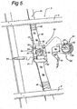
- FIG. 5 A variant of the present invention is shown in Fig. 5 .
- a roof 2 is shown, on which a belt 45 has been provided.
- This belt consists of belt parts 46 and 47.
- Belt part 47 is joined to roof 2 in some way or other, such as by gluing, screwing and the like.
- Belt part 46 is fixed to belt part 47 in periodic locations, for example with the aid of stitching 48.
- Belt part 46 is longer than belt part 47 between two locations 48.
- the engagement members or anchorages 50 which provided with to longitudinal slots 51 are positioned between two tile battens 6. These slots are designed to take loop parts 52 and belt part 46 through them. By then inserting locking strips 53, anchorage 50 is joined in an immovable manner to belt part 46 and thus to belt part 47.
- Anchorage 50 is provided with a coupling part 54 consisting of a circular opening 55 with rear recess 56 and slots 57 opening into the rear recess.
- a safety lanyard 60 is also shown in Fig. 5 .
- This consists of a belt 61 and a further coupling part 62.
- the further coupling part consists of a bearer 63 that is joined to belt 61 and an operating knob 64 that can be turned relative thereto. Lips 65 can be rotated by this means.
- the various features are so designed that bearer 63 can be placed only in one position with respect to anchorage 50.
- the construction is preferably made self-seeking. If the locking lips 65 move through the openings 57 in that position the user notices that full engagement between bearer 63 and anchorage 50 takes place. By then turning knob 64 the locking lips 65 are moved away from the slots 57 into the rear recess 56 and locking takes place in this way.
Landscapes
- Engineering & Computer Science (AREA)
- Architecture (AREA)
- Mechanical Engineering (AREA)
- Civil Engineering (AREA)
- Structural Engineering (AREA)
- Emergency Lowering Means (AREA)
- Burglar Alarm Systems (AREA)
Description
- The present invention relates to an assembly comprising a pitched roof and a belt fixed to said roof, which belt extends in the direction of the pitch of said roof, wherein said roof comprises a structural part, provided with horizontal battens for supporting roof covering elements thereon, said belt being fixed to said structural part under said battens and extends from top to bottom underneath said horizontal battens.
- Such an assembly is disclosed in
EP 0 074 011 . In this publication a rafter roof is described, the tile battens being linked to one another by a strip that takes up the load and is fixed to the rafters. -
FR 2 593 542 - After completion of the work, the construction comprising the belt described above is removed.
- Access to pitched roofs on which tiles or other roof covering elements have been fitted is effected by laying aside the tiles concerned and the person accessing the roof supports himself on the tile battens. However, when a roof becomes older and/or if there are knots or the like in the tile battens it cannot be guaranteed that the tile battens are able to support the weight of the person concerned. It is also possible that said person loses his footing. In all cases there is the risk that he falls from the roof, with all the associates consequences.
- Therefore increasingly more stringent safety regulations are being introduced by the government. Ultimately, people who access the roof must be firmly, fastened to an anchorage point in a safe manner under all circumstances, so that in the case of a possible fall the person does not slip off the roof, but the consequences thereof are restricted. Another safety measure consists in installing scaffolding and fitting nets.
- Such a safety measure can, for example, be realised starting from the belt described in
FR 2 593 542 A - In order to solve this problem it is proposed in the art to provide hooks that are permanently present. These extend to the exterior between the roof covering elements and a lanyard or the like can be fastened thereto. Although such a construction is adequate, in principle each protruding part constitutes a risk with regard to leakage of the roof. Moreover, it must be guaranteed that such a hook is fixed to the roof sufficiently firmly, which imposes particular requirements on the construction. Moreover, there is a risk that if the person on the roof still takes a tumble despite everything, he will be injured by these protruding parts.
- The system described in
EP 0 074 011 is not intended at all as a safety measure. - The aim of the present invention is to provide a safety system that does not have these disadvantages, that is to say can be installed permanently, is easily accessible and does not have the risk of injuring the user.
- This aim is realised with the assembly disclosed in claim 1 and the method of
claim 14. - Here structural part must be understood to be any type of roof boarding or roof construction, with or without layers of insulation and further soundproofing and/or water-resistant layers. The present invention can be used with constructions where the horizontal battens that support the roof covering elements, such as tiles, are some distance away from the roof slab. For this purpose, in general there will be vertical battens that extend from top to bottom. The anchor belt according to the present invention can be permanently installed in the gap between these vertical battens. This belt extends from top to bottom and is anchored to the roof slab under the horizontal battens at a number of fixing points. Such anchoring is preferably made where The beams are located under the roof slab Should one of the fixing points give way during use, this has no consequence because of the continuous nature of the belt and the large number of fixing points.
- Another application is with so-called rafter roofs, where the tile battens are fitted directly on supporting rafters for the roof which are of relatively heave construction. With this arrangement the belt is fixed directly on the side or indirectly on the top of the rafter. Consequently, the belt does not have to be joined to the tile battens and can be arranged a slight distance away therefrom.
- The engagement members according to the invention can be simple loops made in the belt.
- According to a further variant of the present invention it is possible to make the engagement members from separate parts, such as from a housing that is provided with a coupling parts A safety lanyard is (temporarily) connected to such a coupling part. Such an engagement member can either be fixed to the belt in advance or can be fixed thereto on the building site.
- According to a particular embodiment of the invention the belt is made up of belt parts that extend in parallel and are, for example, located one above the other. These belt parts are fixed to one another regular distances apart. With this arrangement according to a particularly advantageous embodiment one belt part is fixed to said roof in some way or other and the other belt part serves for fixing the engagement member, such as a housing. With such a construction it is possible, in particular, to fix the belt to the roof in advance (in the construction workshop and/or factory) and to fit the engagement member on site, as a result of which account can be taken of varying distances between the tile battens.
- According to an advantageous embodiment of the invention, the belt consists of a textile fabric. More particularly, the belt consists of a fabric made of plastic material of high tensile strength, such as material that is used in the production of seat belts in vehicles. More particularly, the plastic material that is used can withstand ultraviolet radiation and other external weather effects.
- The person who accesses the roof can be attached to the belt by using a lanyard. A lanyard with self-locking hooks can be provided for this purpose. Grappling constructions can optionally be used. According to an embodiment described above, the anchor belt consists of a belt provided with loops, to which fastenings to the user's lanyard can easily be fitted. According to an advantageous embodiment of the invention, such loops are made, by locally folding over the belt and fixing it to itself. That is to say, there are no breaks in the belt material. It is also possible to make the belt double and to fix the two parts locally to one another. The seatings for lanyard construction are produced in this way.
- When the coupling described above is used the safety lanyard is preferably made up of a belt with a further coupling part, fitted on the free end thereof, with an anchorage from which locking lips protrude such that they can be moved. These can engage or snap into the coupling part. The lanyard described above can be fastened directly to a person, but also to scaffolding or the like, as described below.
- Furthermore, it is possible to fit the engagement members individually. That is to say, only the belt or the like is installed on the roof under the tile battens and the engagement members, such as loops have to be fastened when a person accesses the roof. For this purpose there is preferably a quick coupling system between such individual engagement members and the belt installed on the roof. Such a coupling system is constructed such that there is either perfect locking between belt and engagement member or the engagement member is not fastened to the belt at all, so that an unsafe situation cannot arise.
- The engagement members can then, in particular, be designed for the desired task. Furthermore, separately providing loops gives rise to the advantage that if the loops become worn only the loops have to be replaced and not the entire construction.
- According to an advantageous embodiment of the invention various belts arranged, in parallel alongside one another and extending from top to bottom are installed. If these are installed in such a way that the fixing points for a safety facility, such as a user's lanyard, are at the same height, it is possible to arrange constructions extending horizontally between them without adjustment of such constructions being needed. If, engagement members of the are loops, it is possible to slide a tube, self-locking hooks or adapters of, for example, a quick coupling system through two loops located some distance apart at the same height and to construct scaffolding thereon. It is also possible to install a platform, safety rail, scaffolding or the like in this way.
- It will be understood that as a result of the permanent presence of the anchor belt according to the invention the requisite safety is directly available for all work on the roof.
- Furthermore, it is not necessary to remove the anchor belt. The anchor belt is automatically protected against external weather effects by fitting the roof elements. The presence of the anchor belt has no influence whatsoever on the functioning of the effect of the roof elements. That is to say, the placing thereof is not impeded by the presence of the anchor belt. The length of the belt is preferably between 4 - 14 m. However, it must be understood that it is also possible to position the belt around the roof, i.e. the ridge, so that it extends downwards on either side of a ridge roof. A particularly high degree of safety is obtained as a result. According to an advantageous embodiment of the invention, there are at last five possible anchoring points per metre in the anchor belt.
- It is also possible to make individual openings in the belt for fixing to the engagement member If this is the case, such openings are preferably at the location with multiple material thickness, that is to say in the case of a belt with loop at the location where the loop branches off from the belt.
- The belt according to the present invention can be installed either in a new building or later on. In the case of new building, the anchor belt according to the invention will preferably be installed before fitting the battens extending horizontally. In the case of existing buildings, the belt will be threaded underneath these battens during the fixing thereof.
- The invention will be explained in more detail below with reference to an illustrative embodiment shown in the drawing. In the drawing:
-
Fig. 1 shows, diagrammatically, part of a pitched roof provided with the safety measure according to the present invention; -
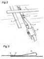
Fig. 2 shows a detail of the construction shown inFig. 1 ; -
Fig. 3 shows a detail of the anchor belt according to the present invention; -
Fig. 4 shows a variant of the construction described above; and -
Fig. 5 shows a further variant of the present invention. - In
Fig. 1 a ridge roof is indicated by 1. The roof construction is conventional and consists of aroof slab 2 that can have some construction or other, that bears onbeams 3.Vertical battens 5 andhorizontal battens 6 are fitted on theroof slab 2. These horizontal battens are some distance away from the roof slab, so that dirt, water and the like can move downwards beneath thehorizontal battens 6 and optimum ventilation of the outer part of the roof is provided. Tiles 4 are laid on the horizontal battens. - According to the present invention an
anchor belt 10 is installed on theroof slab 2 and underneath the horizontal battens. The fixings, which can consist of simple threaded anchor bolts or the like that anchor in theroof slab 2, are indicated by 11. For greater strength thefixings 11 are made in the be 3 passing through theroof slab 2. The anchor belt is provided with engagement members regular intervals apart. According to an embodiment there are at least five possible fixing points per metre and according to an advantageous embodiment two of these are used per metre. - The construction of vertical batten 5 and horizontal batten 6 as well as the fixing 11 can be seen in detail from
Fig. 2 . It can also be seen from this figure that ahook 15 of a safety lanyard or the like has been fitted inloop 12. - It can be seen from
Fig. 3 that the loops are produced by folding over part of the belt material and then fixing it. This fixing can be achieved with sewing by means ofseam 13. The fixing 11 is preferably made inposition 14, by means of which an opening is indicated. - If a roof construction has not yet been provided with the
anchor belt 10 according to the present invention this will preferably be installed from bottom to top. That is to say the lowest fixing point is made while standing on a ladder or scaffolding and in this way work progresses slowly upwards. As a result the worker can secure himself straight away with respect to the roof, so that safety is already available when installing the anchor belt. - It can be seen from
Fig. 1 that varioussuch anchor belts 10 can be installed alongside one another. A tube 8, on which a further scaffolding construction can be installed, can, for example, be inserted in the loops that are thus located alongside one another. This can be repeated at a higher level. Furthermore, such a scaffolding construction can be drawn tight to the roof. The length of the anchor belt of course corresponds to the length of the roof. However, it is also possible to make this twice as long, as a result of which it can be positioned over the ridge and is effective on both sides. - It will be understood that when the tiles 4 are present the anchor belt according to the invention cannot be seen from the outside and is protected against external weather effects. Optionally, indicators for the presence of the anchor belt can be provided at the bottom of the roof, that is to say where the bottom tile emerges above the gutter, so that the person who has to go onto the roof immediately knows that his safety lanyard can be fastened at that point. This can be achieved, for example, by making the end of the belt weather-resistant (part 7), for example by vulcanising and allowing it to protrude in the interface between the bottom tile and gutter. As long as one is not at gutter height, this part is not visible from the outside.
- By means of suitable construction and positioning of the loops or other fastening means with respect to the roof tiles or other roof covering made up of parts it is possible to bring the loops or the like to the outside in the overlap region between two tiles or the like. As a result, the roof remains watertight even when carrying out work. The loops can optionally be provided with a protective sleeve.
- In
Fig. 4 a variant of thebelt 10 described above is indicated by 30. This is not provided with loops but with a number of rectangular openings located a regular distance apart. - The engagement members in the shape of loops are indicated by 32 and are provided at the end with a fixing
section 33. This is fashioned for insertion through theopening 31 to provide secure locking withbelt 30 after turning. In a manner that is not shown in more detail, this construction is made such that there is either a perfect connection betweencomponent 33 andbelt 30 or there is no connection at all. - A variant of the present invention is shown in
Fig. 5 . Aroof 2 is shown, on which abelt 45 has been provided. This belt consists ofbelt parts part 47 is joined toroof 2 in some way or other, such as by gluing, screwing and the like. Beltpart 46 is fixed to beltpart 47 in periodic locations, for example with the aid ofstitching 48. Beltpart 46 is longer thanbelt part 47 between twolocations 48. - According to the variant shown here the engagement members or
anchorages 50, which provided with tolongitudinal slots 51 are positioned between twotile battens 6. These slots are designed to takeloop parts 52 andbelt part 46 through them. By then inserting locking strips 53,anchorage 50 is joined in an immovable manner to beltpart 46 and thus to beltpart 47. -
Anchorage 50 is provided with acoupling part 54 consisting of a circular opening 55 withrear recess 56 andslots 57 opening into the rear recess. - A
safety lanyard 60 is also shown inFig. 5 . This consists of abelt 61 and afurther coupling part 62. The further coupling part consists of abearer 63 that is joined to belt 61 and an operatingknob 64 that can be turned relative thereto.Lips 65 can be rotated by this means. The various features are so designed thatbearer 63 can be placed only in one position with respect toanchorage 50. Furthermore, the construction is preferably made self-seeking. If the lockinglips 65 move through theopenings 57 in that position the user notices that full engagement betweenbearer 63 andanchorage 50 takes place. By then turningknob 64 the lockinglips 65 are moved away from theslots 57 into therear recess 56 and locking takes place in this way. This can optionally be confirmed to the user by means of a distinctly audible click. It will be understood that constructions with lockinglips 65 that can be moved by pushing can also be used, in which case theslots 57 are not needed and snapping into the rear recess takes place. The lockinglips 65 can be moved inwards and unlocking can take place by turning or pushingknob 64. - Some or other construction known in the state of the art can be fastened to
belt 61. - It will be understood that starting from the above concept there are many modifications and further possible applications. These are obvious after reading the above description and fall within the scope of appended claims.
Claims (18)
- Assembly comprising a pitched roof (1) and a belt (10, 30, 45) fixed to said roof, which belt extends in the direction of the pitch of said roof (1), wherein said roof comprises a structural part (2), provided with horizontal battens (6) for supporting roof covering elements (4) thereon, said belt (10, 30, 45) being fixed to said structural part under said battens and extends from top to bottom underneath said horizontal battens (6) characterised in that said assembly comprises a safety lanyard (15, 32, 60)) and in that engagement members (12, 31, 32, 33, 50) are arranged on said belt a regular distance apart, said engagement member (12, 31, 32, 33, 50) designed for coupling said safety lanyard (15, 32, 60) thereto.
- Assembly according to Claim 1, wherein said belt (10, 30, 45) extends underneath said horizontal battens (6) without making contact.
- Assembly according to one of the preceding claims, wherein said battens (6) are fitted on spacers (5) and said belt (10, 30, 45) is installed between two spacers (5) located some distance apart
- Assembly according to the preceding claims, wherein said roof (1) is supported by beams (3) and wherein said belt (10, 30, 45) is fixed to said beams (3) through said roof (1) at regular intervals over the height of said roof.
- Assembly according to one of the preceding claims, wherein said engagement members (12, 31, 32, 33) comprise loops (12, 32) made in the gap between two adjacent horizontal. battens.
- Assembly according to Claim 5, wherein said loops (32) are made such that they are detachable from said belt (30).
- Assembly according to one of the preceding claims, wherein said engagement members comprise an anchorage (50) provided with a coupling part (54).
- Assembly according to one of the preceding claims, wherein said belt (45) comprises belt parts (46, 47) fixed to one another at periodic intervals.
- Assembly according to Claim 8, wherein one belt part (47) is fixed to said roof and one belt part (46) is fixed to said engagement member (50).
- Assembly according to one of the preceding claims, comprising various belts (10) installed alongside one another some distance apart on a roof.
- Assembly according to Claim 10, wherein linking means (8) can be fitted between said belts (10).
- Assembly according to Claim 10 or 11, wherein a further construction is installed on said linking means (8).
- Assembly according to Claim 11 or 12, wherein said linking means (8) comprise a platform.
- Method for installing a fastening point for a safety measure on the assembly of claim 1, wherein the pitched roof, comprises a roof slab and horizontal battens, supporting roof elements, fitted at a distance therefrom; wherein the belt (10, 30, 45) is permanently fixed to the roof slab.
- Method according to Claim 14, wherein said fixing of said belt comprises gluing.
- Method according to Claim 14 or 15, wherein said horizontal battens are fitted thereafter.
- Method according to Claim 14, wherein the fixing of said belt comprises positioning it between said roof stab and under said horizontal battens (6)
- Method according to one of Claims 14 -17, wherein said engagement members (12, 31, 32, 33, 50) are fastened to said belt after fixing said belt to said roof.
Applications Claiming Priority (2)
| Application Number | Priority Date | Filing Date | Title |
|---|---|---|---|
| NL1025885A NL1025885C2 (en) | 2004-04-05 | 2004-04-05 | Protection for a sloping roof. |
| PCT/NL2005/000251 WO2005098166A1 (en) | 2004-04-05 | 2005-04-05 | Safety measure for a pitched roof |
Publications (2)
| Publication Number | Publication Date |
|---|---|
| EP1735509A1 EP1735509A1 (en) | 2006-12-27 |
| EP1735509B1 true EP1735509B1 (en) | 2018-02-28 |
Family
ID=34964404
Family Applications (2)
| Application Number | Title | Priority Date | Filing Date |
|---|---|---|---|
| EP05733690.1A Expired - Lifetime EP1735509B1 (en) | 2004-04-05 | 2005-04-05 | Safety measure for a pitched roof |
| EP05772755A Withdrawn EP1866504A1 (en) | 2004-04-05 | 2005-08-16 | Safety coupling |
Family Applications After (1)
| Application Number | Title | Priority Date | Filing Date |
|---|---|---|---|
| EP05772755A Withdrawn EP1866504A1 (en) | 2004-04-05 | 2005-08-16 | Safety coupling |
Country Status (10)
| Country | Link |
|---|---|
| US (2) | US8177027B2 (en) |
| EP (2) | EP1735509B1 (en) |
| AU (1) | AU2005230948A1 (en) |
| CA (1) | CA2562344C (en) |
| DK (1) | DK1735509T3 (en) |
| ES (1) | ES2664404T3 (en) |
| NL (1) | NL1025885C2 (en) |
| NO (1) | NO20064573L (en) |
| NZ (1) | NZ550357A (en) |
| WO (2) | WO2005098166A1 (en) |
Families Citing this family (10)
| Publication number | Priority date | Publication date | Assignee | Title |
|---|---|---|---|---|
| NL2000482C2 (en) | 2007-02-08 | 2008-08-11 | Daktari V O F | Safety coupling to be fitted on a roof. |
| US20100012426A1 (en) * | 2008-07-15 | 2010-01-21 | Convenient Safety Systems, Inc. | Sloped Roof Safety System |
| NL2003694C2 (en) | 2009-10-22 | 2011-04-27 | Dachfix Gmbh | LOCKING COMPOSITION. |
| CN102947520B (en) * | 2010-05-25 | 2014-12-03 | 绿安全股份有限公司 | Fall arrest system, bucket and bucket for fall arrest system |
| DE202010018632U1 (en) | 2010-10-29 | 2019-03-18 | Luchtankers B.V. | Roof equipped with a security system |
| PT2447437T (en) | 2010-10-29 | 2020-02-03 | Luchtankers B V | Roof provided with a safety system |
| DE202010018523U1 (en) | 2010-10-29 | 2017-05-12 | Flesst B.V. | Roof equipped with a security system |
| US9745753B1 (en) * | 2016-11-02 | 2017-08-29 | Petersen-Dean, Inc. | Notched polymer roofing batten with measured detachable sections |
| WO2021077040A1 (en) | 2019-10-16 | 2021-04-22 | Taaaza Llc | Roof attachment systems and methods |
| US12371912B2 (en) | 2020-08-19 | 2025-07-29 | William Webster Kain | System and method for supporting workers and material on a sloped roof |
Family Cites Families (19)
| Publication number | Priority date | Publication date | Assignee | Title |
|---|---|---|---|---|
| US2487895A (en) * | 1947-08-18 | 1949-11-15 | Ivan E Landstrom | Self-locking separable fastener |
| US2703688A (en) * | 1954-06-23 | 1955-03-08 | William M Shuter | Service bracket |
| US4125282A (en) * | 1977-06-29 | 1978-11-14 | Presto Lock Company, Division Of Walter Kidde & Company, Inc. | Turnbutton latch |
| US4140205A (en) * | 1978-03-15 | 1979-02-20 | Matson Theodore C | Safety release boat trapeze hook |
| US4220328A (en) * | 1978-07-12 | 1980-09-02 | Crush Roy D Jr | Pulling line sport apparatus |
| DE3134483A1 (en) * | 1981-09-01 | 1983-03-10 | Dlw Ag, 7120 Bietigheim-Bissingen | KIT FOR ATTACHING ROOF COVER ELEMENTS, IN PARTICULAR ROOF TILES, SPECIFIC ROOF LATCHES ON A BUILDING ROOF CARRYING HEAT INSULATION ELEMENTS |
| FR2593542B1 (en) | 1986-01-29 | 1988-05-27 | Fel Jean Louis | SCAFFOLDING FOOT DEVICE FOR SLOPED AND / OR FRAGILE SURFACES SUCH AS ROOFS |
| US4852692A (en) * | 1988-06-30 | 1989-08-01 | Davey Roofing, Inc. | Roofing safety device |
| US5137112A (en) * | 1991-09-13 | 1992-08-11 | Steve Nichols | Fall restraint lifeline roof anchor |
| US5361866A (en) * | 1993-09-30 | 1994-11-08 | Michael Bell | Connector assembly for use on scaffolding to prevent a worker from falling |
| US5727646A (en) * | 1995-08-07 | 1998-03-17 | Gray; Geoffrey H. | Retractable fall restraint device |
| US5699875A (en) * | 1995-10-31 | 1997-12-23 | Spancrete Industries, Inc. | Lifeline anchor |
| US5687535A (en) * | 1995-11-03 | 1997-11-18 | D B Industries, Inc. | Detachable roof anchor |
| GB2313396B (en) * | 1996-04-18 | 2000-08-30 | Acimex | Fall arrest device |
| US6745869B2 (en) * | 2001-01-22 | 2004-06-08 | Roofmates, Incorporated | Roofmates™ roofing accessories |
| US6779316B2 (en) * | 2001-01-31 | 2004-08-24 | Kenneth Carroll | Safety anchor |
| FR2855418B1 (en) * | 2003-05-28 | 2005-07-29 | Froment | CONNECTING DEVICE FOR RECEIVING A SECURITY SYSTEM, AND PORTABLE SECURITY ASSEMBLY PROVIDED WITH AT LEAST ONE SUCH ORGAN |
| AU2004272012B2 (en) * | 2003-09-05 | 2009-09-24 | D B Industries, Llc | Dorsal pad assembly for use with a safety harness |
| US7073627B2 (en) * | 2003-09-05 | 2006-07-11 | D B Industries, Inc. | Dorsal pad assembly for use with a safety harness |
-
2004
- 2004-04-05 NL NL1025885A patent/NL1025885C2/en not_active IP Right Cessation
-
2005
- 2005-04-05 ES ES05733690.1T patent/ES2664404T3/en not_active Expired - Lifetime
- 2005-04-05 NZ NZ550357A patent/NZ550357A/en not_active IP Right Cessation
- 2005-04-05 US US11/547,772 patent/US8177027B2/en not_active Expired - Fee Related
- 2005-04-05 WO PCT/NL2005/000251 patent/WO2005098166A1/en not_active Ceased
- 2005-04-05 AU AU2005230948A patent/AU2005230948A1/en not_active Abandoned
- 2005-04-05 EP EP05733690.1A patent/EP1735509B1/en not_active Expired - Lifetime
- 2005-04-05 CA CA2562344A patent/CA2562344C/en not_active Expired - Fee Related
- 2005-04-05 DK DK05733690.1T patent/DK1735509T3/en active
- 2005-08-16 EP EP05772755A patent/EP1866504A1/en not_active Withdrawn
- 2005-08-16 US US11/910,864 patent/US20090200112A1/en not_active Abandoned
- 2005-08-16 WO PCT/NL2005/000590 patent/WO2006107189A1/en not_active Ceased
-
2006
- 2006-10-09 NO NO20064573A patent/NO20064573L/en not_active Application Discontinuation
Also Published As
| Publication number | Publication date |
|---|---|
| NZ550357A (en) | 2010-04-30 |
| US20090200112A1 (en) | 2009-08-13 |
| EP1735509A1 (en) | 2006-12-27 |
| EP1866504A1 (en) | 2007-12-19 |
| US20080017446A1 (en) | 2008-01-24 |
| NO20064573L (en) | 2007-01-04 |
| CA2562344A1 (en) | 2005-10-20 |
| CA2562344C (en) | 2012-10-02 |
| AU2005230948A1 (en) | 2005-10-20 |
| DK1735509T3 (en) | 2018-04-23 |
| US8177027B2 (en) | 2012-05-15 |
| ES2664404T3 (en) | 2018-04-19 |
| NL1025885C2 (en) | 2005-10-10 |
| WO2005098166A1 (en) | 2005-10-20 |
| WO2006107189A1 (en) | 2006-10-12 |
Similar Documents
| Publication | Publication Date | Title |
|---|---|---|
| US5890328A (en) | Roof eave ventilation safety device | |
| EP2633135B1 (en) | Roof provided with a safety system | |
| US8177027B2 (en) | Safety measure for a pitched roof | |
| JP2011516754A (en) | Railway arched lining and mezzanine | |
| EP0865552A1 (en) | Roofing ridge installation | |
| EP2872709B1 (en) | Pitched roof structures and their methods of assembly and construction | |
| CA2909214A1 (en) | Truss girder for a weather protection roof as well as weather protection roof with several truss girders | |
| AU2020101207A4 (en) | Ladder safety device | |
| AU2009206174A1 (en) | Fall prevention system | |
| JP4173033B2 (en) | Safety structure for high-rise work in buildings | |
| GB2440417A (en) | Fall protection system | |
| JP3225395B2 (en) | Unit type metal tile roof, unit type metal tile roof set and construction method | |
| JP3670136B2 (en) | Handrail support structure | |
| EP4008854B1 (en) | System for covering a roof | |
| RU107206U1 (en) | PEDAL ROOF DESIGN FOR WOODEN STRUCTURE | |
| AU782527B2 (en) | Mounting bracket | |
| AU2021221828B2 (en) | Improvements Relating to Rooftop Walkways | |
| AU2019204459B2 (en) | A Roof | |
| AU661568B2 (en) | Support structure | |
| JP2004183203A (en) | Safely device for work on roof | |
| AU751461B1 (en) | Roof safety guardrail system | |
| KR20250158558A (en) | Roof panel equipped with a safety ring for fall prevention | |
| JP4428244B2 (en) | Fixing structure of fixing bracket and base mesh | |
| AU693619B2 (en) | Safety system for elevated structures | |
| WO1995023901A1 (en) | Device in connection with a building |
Legal Events
| Date | Code | Title | Description |
|---|---|---|---|
| PUAI | Public reference made under article 153(3) epc to a published international application that has entered the european phase |
Free format text: ORIGINAL CODE: 0009012 |
|
| 17P | Request for examination filed |
Effective date: 20061106 |
|
| AK | Designated contracting states |
Kind code of ref document: A1 Designated state(s): AT BE BG CH CY CZ DE DK EE ES FI FR GB GR HU IE IS IT LI LT LU MC NL PL PT RO SE SI SK TR |
|
| RAX | Requested extension states of the european patent have changed |
Extension state: YU Payment date: 20061106 Extension state: HR Payment date: 20061106 Extension state: BA Payment date: 20061106 Extension state: LV Payment date: 20061106 |
|
| RAX | Requested extension states of the european patent have changed |
Extension state: BA Payment date: 20061106 Extension state: LV Payment date: 20061106 Extension state: YU Payment date: 20061106 Extension state: HR Payment date: 20061106 |
|
| RAP1 | Party data changed (applicant data changed or rights of an application transferred) |
Owner name: DACHBAND GMBH |
|
| 17Q | First examination report despatched |
Effective date: 20130201 |
|
| GRAP | Despatch of communication of intention to grant a patent |
Free format text: ORIGINAL CODE: EPIDOSNIGR1 |
|
| INTG | Intention to grant announced |
Effective date: 20150915 |
|
| INTG | Intention to grant announced |
Effective date: 20160217 |
|
| GRAJ | Information related to disapproval of communication of intention to grant by the applicant or resumption of examination proceedings by the epo deleted |
Free format text: ORIGINAL CODE: EPIDOSDIGR1 |
|
| GRAP | Despatch of communication of intention to grant a patent |
Free format text: ORIGINAL CODE: EPIDOSNIGR1 |
|
| INTC | Intention to grant announced (deleted) | ||
| INTG | Intention to grant announced |
Effective date: 20160726 |
|
| GRAJ | Information related to disapproval of communication of intention to grant by the applicant or resumption of examination proceedings by the epo deleted |
Free format text: ORIGINAL CODE: EPIDOSDIGR1 |
|
| INTC | Intention to grant announced (deleted) | ||
| GRAP | Despatch of communication of intention to grant a patent |
Free format text: ORIGINAL CODE: EPIDOSNIGR1 |
|
| INTG | Intention to grant announced |
Effective date: 20170518 |
|
| GRAS | Grant fee paid |
Free format text: ORIGINAL CODE: EPIDOSNIGR3 |
|
| GRAA | (expected) grant |
Free format text: ORIGINAL CODE: 0009210 |
|
| AK | Designated contracting states |
Kind code of ref document: B1 Designated state(s): AT BE BG CH CY CZ DE DK EE ES FI FR GB GR HU IE IS IT LI LT LU MC NL PL PT RO SE SI SK TR |
|
| AX | Request for extension of the european patent |
Extension state: BA HR LV YU |
|
| REG | Reference to a national code |
Ref country code: GB Ref legal event code: FG4D Ref country code: CH Ref legal event code: EP |
|
| REG | Reference to a national code |
Ref country code: AT Ref legal event code: REF Ref document number: 974313 Country of ref document: AT Kind code of ref document: T Effective date: 20180315 |
|
| REG | Reference to a national code |
Ref country code: IE Ref legal event code: FG4D |
|
| REG | Reference to a national code |
Ref country code: DE Ref legal event code: R096 Ref document number: 602005053564 Country of ref document: DE |
|
| REG | Reference to a national code |
Ref country code: ES Ref legal event code: FG2A Ref document number: 2664404 Country of ref document: ES Kind code of ref document: T3 Effective date: 20180419 |
|
| REG | Reference to a national code |
Ref country code: DK Ref legal event code: T3 Effective date: 20180416 |
|
| REG | Reference to a national code |
Ref country code: FR Ref legal event code: PLFP Year of fee payment: 14 |
|
| REG | Reference to a national code |
Ref country code: SE Ref legal event code: TRGR |
|
| REG | Reference to a national code |
Ref country code: NL Ref legal event code: FP |
|
| PGFP | Annual fee paid to national office [announced via postgrant information from national office to epo] |
Ref country code: LU Payment date: 20180424 Year of fee payment: 14 Ref country code: NL Payment date: 20180413 Year of fee payment: 14 |
|
| REG | Reference to a national code |
Ref country code: LT Ref legal event code: MG4D |
|
| PG25 | Lapsed in a contracting state [announced via postgrant information from national office to epo] |
Ref country code: LT Free format text: LAPSE BECAUSE OF FAILURE TO SUBMIT A TRANSLATION OF THE DESCRIPTION OR TO PAY THE FEE WITHIN THE PRESCRIBED TIME-LIMIT Effective date: 20180228 Ref country code: CY Free format text: LAPSE BECAUSE OF FAILURE TO SUBMIT A TRANSLATION OF THE DESCRIPTION OR TO PAY THE FEE WITHIN THE PRESCRIBED TIME-LIMIT Effective date: 20180228 |
|
| PGFP | Annual fee paid to national office [announced via postgrant information from national office to epo] |
Ref country code: IE Payment date: 20180427 Year of fee payment: 14 Ref country code: ES Payment date: 20180522 Year of fee payment: 14 Ref country code: FI Payment date: 20180420 Year of fee payment: 14 Ref country code: CH Payment date: 20180426 Year of fee payment: 14 Ref country code: DK Payment date: 20180423 Year of fee payment: 14 |
|
| PG25 | Lapsed in a contracting state [announced via postgrant information from national office to epo] |
Ref country code: BG Free format text: LAPSE BECAUSE OF FAILURE TO SUBMIT A TRANSLATION OF THE DESCRIPTION OR TO PAY THE FEE WITHIN THE PRESCRIBED TIME-LIMIT Effective date: 20180528 Ref country code: GR Free format text: LAPSE BECAUSE OF FAILURE TO SUBMIT A TRANSLATION OF THE DESCRIPTION OR TO PAY THE FEE WITHIN THE PRESCRIBED TIME-LIMIT Effective date: 20180529 |
|
| PGFP | Annual fee paid to national office [announced via postgrant information from national office to epo] |
Ref country code: BE Payment date: 20180420 Year of fee payment: 14 Ref country code: IT Payment date: 20180424 Year of fee payment: 14 Ref country code: FR Payment date: 20180426 Year of fee payment: 14 Ref country code: AT Payment date: 20180426 Year of fee payment: 14 |
|
| PGFP | Annual fee paid to national office [announced via postgrant information from national office to epo] |
Ref country code: SE Payment date: 20180427 Year of fee payment: 14 |
|
| PG25 | Lapsed in a contracting state [announced via postgrant information from national office to epo] |
Ref country code: PL Free format text: LAPSE BECAUSE OF FAILURE TO SUBMIT A TRANSLATION OF THE DESCRIPTION OR TO PAY THE FEE WITHIN THE PRESCRIBED TIME-LIMIT Effective date: 20180228 Ref country code: RO Free format text: LAPSE BECAUSE OF FAILURE TO SUBMIT A TRANSLATION OF THE DESCRIPTION OR TO PAY THE FEE WITHIN THE PRESCRIBED TIME-LIMIT Effective date: 20180228 Ref country code: EE Free format text: LAPSE BECAUSE OF FAILURE TO SUBMIT A TRANSLATION OF THE DESCRIPTION OR TO PAY THE FEE WITHIN THE PRESCRIBED TIME-LIMIT Effective date: 20180228 |
|
| PGFP | Annual fee paid to national office [announced via postgrant information from national office to epo] |
Ref country code: GB Payment date: 20180405 Year of fee payment: 14 Ref country code: DE Payment date: 20180629 Year of fee payment: 14 |
|
| REG | Reference to a national code |
Ref country code: DE Ref legal event code: R097 Ref document number: 602005053564 Country of ref document: DE |
|
| PG25 | Lapsed in a contracting state [announced via postgrant information from national office to epo] |
Ref country code: SK Free format text: LAPSE BECAUSE OF FAILURE TO SUBMIT A TRANSLATION OF THE DESCRIPTION OR TO PAY THE FEE WITHIN THE PRESCRIBED TIME-LIMIT Effective date: 20180228 Ref country code: MC Free format text: LAPSE BECAUSE OF FAILURE TO SUBMIT A TRANSLATION OF THE DESCRIPTION OR TO PAY THE FEE WITHIN THE PRESCRIBED TIME-LIMIT Effective date: 20180228 Ref country code: CZ Free format text: LAPSE BECAUSE OF FAILURE TO SUBMIT A TRANSLATION OF THE DESCRIPTION OR TO PAY THE FEE WITHIN THE PRESCRIBED TIME-LIMIT Effective date: 20180228 |
|
| PLBE | No opposition filed within time limit |
Free format text: ORIGINAL CODE: 0009261 |
|
| STAA | Information on the status of an ep patent application or granted ep patent |
Free format text: STATUS: NO OPPOSITION FILED WITHIN TIME LIMIT |
|
| 26N | No opposition filed |
Effective date: 20181129 |
|
| PG25 | Lapsed in a contracting state [announced via postgrant information from national office to epo] |
Ref country code: SI Free format text: LAPSE BECAUSE OF FAILURE TO SUBMIT A TRANSLATION OF THE DESCRIPTION OR TO PAY THE FEE WITHIN THE PRESCRIBED TIME-LIMIT Effective date: 20180228 |
|
| REG | Reference to a national code |
Ref country code: AT Ref legal event code: UEP Ref document number: 974313 Country of ref document: AT Kind code of ref document: T Effective date: 20180228 |
|
| REG | Reference to a national code |
Ref country code: DE Ref legal event code: R119 Ref document number: 602005053564 Country of ref document: DE |
|
| REG | Reference to a national code |
Ref country code: CH Ref legal event code: PL |
|
| REG | Reference to a national code |
Ref country code: DK Ref legal event code: EBP Effective date: 20190430 |
|
| REG | Reference to a national code |
Ref country code: SE Ref legal event code: EUG |
|
| REG | Reference to a national code |
Ref country code: NL Ref legal event code: MM Effective date: 20190501 |
|
| REG | Reference to a national code |
Ref country code: AT Ref legal event code: MM01 Ref document number: 974313 Country of ref document: AT Kind code of ref document: T Effective date: 20190405 |
|
| REG | Reference to a national code |
Ref country code: BE Ref legal event code: MM Effective date: 20190430 |
|
| GBPC | Gb: european patent ceased through non-payment of renewal fee |
Effective date: 20190405 |
|
| PG25 | Lapsed in a contracting state [announced via postgrant information from national office to epo] |
Ref country code: LU Free format text: LAPSE BECAUSE OF NON-PAYMENT OF DUE FEES Effective date: 20190405 |
|
| PG25 | Lapsed in a contracting state [announced via postgrant information from national office to epo] |
Ref country code: DE Free format text: LAPSE BECAUSE OF NON-PAYMENT OF DUE FEES Effective date: 20191101 Ref country code: CH Free format text: LAPSE BECAUSE OF NON-PAYMENT OF DUE FEES Effective date: 20190430 Ref country code: SE Free format text: LAPSE BECAUSE OF NON-PAYMENT OF DUE FEES Effective date: 20190406 Ref country code: GB Free format text: LAPSE BECAUSE OF NON-PAYMENT OF DUE FEES Effective date: 20190405 Ref country code: AT Free format text: LAPSE BECAUSE OF NON-PAYMENT OF DUE FEES Effective date: 20190405 Ref country code: FI Free format text: LAPSE BECAUSE OF NON-PAYMENT OF DUE FEES Effective date: 20190405 Ref country code: LI Free format text: LAPSE BECAUSE OF NON-PAYMENT OF DUE FEES Effective date: 20190430 Ref country code: NL Free format text: LAPSE BECAUSE OF NON-PAYMENT OF DUE FEES Effective date: 20190501 |
|
| PG25 | Lapsed in a contracting state [announced via postgrant information from national office to epo] |
Ref country code: FR Free format text: LAPSE BECAUSE OF NON-PAYMENT OF DUE FEES Effective date: 20190430 Ref country code: BE Free format text: LAPSE BECAUSE OF NON-PAYMENT OF DUE FEES Effective date: 20190430 |
|
| PG25 | Lapsed in a contracting state [announced via postgrant information from national office to epo] |
Ref country code: TR Free format text: LAPSE BECAUSE OF FAILURE TO SUBMIT A TRANSLATION OF THE DESCRIPTION OR TO PAY THE FEE WITHIN THE PRESCRIBED TIME-LIMIT Effective date: 20180228 |
|
| PG25 | Lapsed in a contracting state [announced via postgrant information from national office to epo] |
Ref country code: IT Free format text: LAPSE BECAUSE OF NON-PAYMENT OF DUE FEES Effective date: 20190405 Ref country code: IE Free format text: LAPSE BECAUSE OF NON-PAYMENT OF DUE FEES Effective date: 20190405 Ref country code: DK Free format text: LAPSE BECAUSE OF NON-PAYMENT OF DUE FEES Effective date: 20190430 |
|
| PG25 | Lapsed in a contracting state [announced via postgrant information from national office to epo] |
Ref country code: PT Free format text: LAPSE BECAUSE OF FAILURE TO SUBMIT A TRANSLATION OF THE DESCRIPTION OR TO PAY THE FEE WITHIN THE PRESCRIBED TIME-LIMIT Effective date: 20180228 Ref country code: HU Free format text: LAPSE BECAUSE OF FAILURE TO SUBMIT A TRANSLATION OF THE DESCRIPTION OR TO PAY THE FEE WITHIN THE PRESCRIBED TIME-LIMIT; INVALID AB INITIO Effective date: 20050405 |
|
| PG25 | Lapsed in a contracting state [announced via postgrant information from national office to epo] |
Ref country code: IS Free format text: LAPSE BECAUSE OF FAILURE TO SUBMIT A TRANSLATION OF THE DESCRIPTION OR TO PAY THE FEE WITHIN THE PRESCRIBED TIME-LIMIT Effective date: 20180628 |
|
| REG | Reference to a national code |
Ref country code: ES Ref legal event code: FD2A Effective date: 20200828 |
|
| PG25 | Lapsed in a contracting state [announced via postgrant information from national office to epo] |
Ref country code: ES Free format text: LAPSE BECAUSE OF NON-PAYMENT OF DUE FEES Effective date: 20190406 |