EP1735236B1 - Hydrogen storage and supply method - Google Patents
Hydrogen storage and supply method Download PDFInfo
- Publication number
- EP1735236B1 EP1735236B1 EP05725984.8A EP05725984A EP1735236B1 EP 1735236 B1 EP1735236 B1 EP 1735236B1 EP 05725984 A EP05725984 A EP 05725984A EP 1735236 B1 EP1735236 B1 EP 1735236B1
- Authority
- EP
- European Patent Office
- Prior art keywords
- hydrogen
- stream
- product
- gaseous
- pipeline
- Prior art date
- Legal status (The legal status is an assumption and is not a legal conclusion. Google has not performed a legal analysis and makes no representation as to the accuracy of the status listed.)
- Expired - Lifetime
Links
Images
Classifications
-
- C—CHEMISTRY; METALLURGY
- C01—INORGANIC CHEMISTRY
- C01B—NON-METALLIC ELEMENTS; COMPOUNDS THEREOF; METALLOIDS OR COMPOUNDS THEREOF NOT COVERED BY SUBCLASS C01C
- C01B3/00—Hydrogen; Gaseous mixtures containing hydrogen; Separation of hydrogen from mixtures containing it; Purification of hydrogen; Reversible storage of hydrogen
- C01B3/50—Separation of hydrogen or hydrogen-containing gases from gaseous mixtures, e.g. purification
-
- B—PERFORMING OPERATIONS; TRANSPORTING
- B01—PHYSICAL OR CHEMICAL PROCESSES OR APPARATUS IN GENERAL
- B01D—SEPARATION
- B01D53/00—Separation of gases or vapours; Recovering vapours of volatile solvents from gases; Chemical or biological purification of waste gases, e.g. engine exhaust gases, smoke, fumes, flue gases, aerosols
- B01D53/02—Separation of gases or vapours; Recovering vapours of volatile solvents from gases; Chemical or biological purification of waste gases, e.g. engine exhaust gases, smoke, fumes, flue gases, aerosols by adsorption, e.g. preparative gas chromatography
- B01D53/04—Separation of gases or vapours; Recovering vapours of volatile solvents from gases; Chemical or biological purification of waste gases, e.g. engine exhaust gases, smoke, fumes, flue gases, aerosols by adsorption, e.g. preparative gas chromatography with stationary adsorbents
- B01D53/0462—Temperature swing adsorption
-
- C—CHEMISTRY; METALLURGY
- C01—INORGANIC CHEMISTRY
- C01B—NON-METALLIC ELEMENTS; COMPOUNDS THEREOF; METALLOIDS OR COMPOUNDS THEREOF NOT COVERED BY SUBCLASS C01C
- C01B3/00—Hydrogen; Gaseous mixtures containing hydrogen; Separation of hydrogen from mixtures containing it; Purification of hydrogen; Reversible storage of hydrogen
- C01B3/50—Separation of hydrogen or hydrogen-containing gases from gaseous mixtures, e.g. purification
- C01B3/56—Separation of hydrogen or hydrogen-containing gases from gaseous mixtures, e.g. purification by contacting with solids; Regeneration of used solids
-
- B—PERFORMING OPERATIONS; TRANSPORTING
- B01—PHYSICAL OR CHEMICAL PROCESSES OR APPARATUS IN GENERAL
- B01D—SEPARATION
- B01D2256/00—Main component in the product gas stream after treatment
- B01D2256/16—Hydrogen
-
- B—PERFORMING OPERATIONS; TRANSPORTING
- B01—PHYSICAL OR CHEMICAL PROCESSES OR APPARATUS IN GENERAL
- B01D—SEPARATION
- B01D2257/00—Components to be removed
- B01D2257/10—Single element gases other than halogens
- B01D2257/11—Noble gases
-
- B—PERFORMING OPERATIONS; TRANSPORTING
- B01—PHYSICAL OR CHEMICAL PROCESSES OR APPARATUS IN GENERAL
- B01D—SEPARATION
- B01D2257/00—Components to be removed
- B01D2257/30—Sulfur compounds
- B01D2257/304—Hydrogen sulfide
-
- B—PERFORMING OPERATIONS; TRANSPORTING
- B01—PHYSICAL OR CHEMICAL PROCESSES OR APPARATUS IN GENERAL
- B01D—SEPARATION
- B01D2257/00—Components to be removed
- B01D2257/50—Carbon oxides
- B01D2257/502—Carbon monoxide
-
- B—PERFORMING OPERATIONS; TRANSPORTING
- B01—PHYSICAL OR CHEMICAL PROCESSES OR APPARATUS IN GENERAL
- B01D—SEPARATION
- B01D2257/00—Components to be removed
- B01D2257/50—Carbon oxides
- B01D2257/504—Carbon dioxide
-
- B—PERFORMING OPERATIONS; TRANSPORTING
- B01—PHYSICAL OR CHEMICAL PROCESSES OR APPARATUS IN GENERAL
- B01D—SEPARATION
- B01D2257/00—Components to be removed
- B01D2257/70—Organic compounds not provided for in groups B01D2257/00 - B01D2257/602
- B01D2257/702—Hydrocarbons
- B01D2257/7022—Aliphatic hydrocarbons
- B01D2257/7025—Methane
-
- B—PERFORMING OPERATIONS; TRANSPORTING
- B01—PHYSICAL OR CHEMICAL PROCESSES OR APPARATUS IN GENERAL
- B01D—SEPARATION
- B01D2257/00—Components to be removed
- B01D2257/80—Water
-
- B—PERFORMING OPERATIONS; TRANSPORTING
- B01—PHYSICAL OR CHEMICAL PROCESSES OR APPARATUS IN GENERAL
- B01D—SEPARATION
- B01D2259/00—Type of treatment
- B01D2259/40—Further details for adsorption processes and devices
- B01D2259/40007—Controlling pressure or temperature swing adsorption
-
- B—PERFORMING OPERATIONS; TRANSPORTING
- B01—PHYSICAL OR CHEMICAL PROCESSES OR APPARATUS IN GENERAL
- B01D—SEPARATION
- B01D2259/00—Type of treatment
- B01D2259/40—Further details for adsorption processes and devices
- B01D2259/40011—Methods relating to the process cycle in pressure or temperature swing adsorption
- B01D2259/40043—Purging
- B01D2259/4005—Nature of purge gas
- B01D2259/40052—Recycled product or process gas
-
- B—PERFORMING OPERATIONS; TRANSPORTING
- B01—PHYSICAL OR CHEMICAL PROCESSES OR APPARATUS IN GENERAL
- B01D—SEPARATION
- B01D2259/00—Type of treatment
- B01D2259/40—Further details for adsorption processes and devices
- B01D2259/40011—Methods relating to the process cycle in pressure or temperature swing adsorption
- B01D2259/40077—Direction of flow
- B01D2259/40081—Counter-current
-
- B—PERFORMING OPERATIONS; TRANSPORTING
- B01—PHYSICAL OR CHEMICAL PROCESSES OR APPARATUS IN GENERAL
- B01D—SEPARATION
- B01D2259/00—Type of treatment
- B01D2259/40—Further details for adsorption processes and devices
- B01D2259/40083—Regeneration of adsorbents in processes other than pressure or temperature swing adsorption
- B01D2259/40088—Regeneration of adsorbents in processes other than pressure or temperature swing adsorption by heating
- B01D2259/4009—Regeneration of adsorbents in processes other than pressure or temperature swing adsorption by heating using hot gas
-
- B—PERFORMING OPERATIONS; TRANSPORTING
- B01—PHYSICAL OR CHEMICAL PROCESSES OR APPARATUS IN GENERAL
- B01D—SEPARATION
- B01D53/00—Separation of gases or vapours; Recovering vapours of volatile solvents from gases; Chemical or biological purification of waste gases, e.g. engine exhaust gases, smoke, fumes, flue gases, aerosols
- B01D53/26—Drying gases or vapours
- B01D53/261—Drying gases or vapours by adsorption
-
- C—CHEMISTRY; METALLURGY
- C01—INORGANIC CHEMISTRY
- C01B—NON-METALLIC ELEMENTS; COMPOUNDS THEREOF; METALLOIDS OR COMPOUNDS THEREOF NOT COVERED BY SUBCLASS C01C
- C01B2203/00—Integrated processes for the production of hydrogen or synthesis gas
- C01B2203/02—Processes for making hydrogen or synthesis gas
- C01B2203/0205—Processes for making hydrogen or synthesis gas containing a reforming step
- C01B2203/0227—Processes for making hydrogen or synthesis gas containing a reforming step containing a catalytic reforming step
- C01B2203/0233—Processes for making hydrogen or synthesis gas containing a reforming step containing a catalytic reforming step the reforming step being a steam reforming step
-
- C—CHEMISTRY; METALLURGY
- C01—INORGANIC CHEMISTRY
- C01B—NON-METALLIC ELEMENTS; COMPOUNDS THEREOF; METALLOIDS OR COMPOUNDS THEREOF NOT COVERED BY SUBCLASS C01C
- C01B2203/00—Integrated processes for the production of hydrogen or synthesis gas
- C01B2203/04—Integrated processes for the production of hydrogen or synthesis gas containing a purification step for the hydrogen or the synthesis gas
- C01B2203/042—Purification by adsorption on solids
- C01B2203/043—Regenerative adsorption process in two or more beds, one for adsorption, the other for regeneration
-
- C—CHEMISTRY; METALLURGY
- C01—INORGANIC CHEMISTRY
- C01B—NON-METALLIC ELEMENTS; COMPOUNDS THEREOF; METALLOIDS OR COMPOUNDS THEREOF NOT COVERED BY SUBCLASS C01C
- C01B2203/00—Integrated processes for the production of hydrogen or synthesis gas
- C01B2203/04—Integrated processes for the production of hydrogen or synthesis gas containing a purification step for the hydrogen or the synthesis gas
- C01B2203/0465—Composition of the impurity
- C01B2203/0475—Composition of the impurity the impurity being carbon dioxide
-
- C—CHEMISTRY; METALLURGY
- C01—INORGANIC CHEMISTRY
- C01B—NON-METALLIC ELEMENTS; COMPOUNDS THEREOF; METALLOIDS OR COMPOUNDS THEREOF NOT COVERED BY SUBCLASS C01C
- C01B2203/00—Integrated processes for the production of hydrogen or synthesis gas
- C01B2203/04—Integrated processes for the production of hydrogen or synthesis gas containing a purification step for the hydrogen or the synthesis gas
- C01B2203/0465—Composition of the impurity
- C01B2203/0485—Composition of the impurity the impurity being a sulfur compound
-
- C—CHEMISTRY; METALLURGY
- C01—INORGANIC CHEMISTRY
- C01B—NON-METALLIC ELEMENTS; COMPOUNDS THEREOF; METALLOIDS OR COMPOUNDS THEREOF NOT COVERED BY SUBCLASS C01C
- C01B2203/00—Integrated processes for the production of hydrogen or synthesis gas
- C01B2203/04—Integrated processes for the production of hydrogen or synthesis gas containing a purification step for the hydrogen or the synthesis gas
- C01B2203/0465—Composition of the impurity
- C01B2203/0495—Composition of the impurity the impurity being water
-
- C—CHEMISTRY; METALLURGY
- C01—INORGANIC CHEMISTRY
- C01B—NON-METALLIC ELEMENTS; COMPOUNDS THEREOF; METALLOIDS OR COMPOUNDS THEREOF NOT COVERED BY SUBCLASS C01C
- C01B2203/00—Integrated processes for the production of hydrogen or synthesis gas
- C01B2203/14—Details of the flowsheet
- C01B2203/146—At least two purification steps in series
- C01B2203/147—Three or more purification steps in series
-
- Y—GENERAL TAGGING OF NEW TECHNOLOGICAL DEVELOPMENTS; GENERAL TAGGING OF CROSS-SECTIONAL TECHNOLOGIES SPANNING OVER SEVERAL SECTIONS OF THE IPC; TECHNICAL SUBJECTS COVERED BY FORMER USPC CROSS-REFERENCE ART COLLECTIONS [XRACs] AND DIGESTS
- Y02—TECHNOLOGIES OR APPLICATIONS FOR MITIGATION OR ADAPTATION AGAINST CLIMATE CHANGE
- Y02C—CAPTURE, STORAGE, SEQUESTRATION OR DISPOSAL OF GREENHOUSE GASES [GHG]
- Y02C20/00—Capture or disposal of greenhouse gases
- Y02C20/20—Capture or disposal of greenhouse gases of methane
-
- Y—GENERAL TAGGING OF NEW TECHNOLOGICAL DEVELOPMENTS; GENERAL TAGGING OF CROSS-SECTIONAL TECHNOLOGIES SPANNING OVER SEVERAL SECTIONS OF THE IPC; TECHNICAL SUBJECTS COVERED BY FORMER USPC CROSS-REFERENCE ART COLLECTIONS [XRACs] AND DIGESTS
- Y02—TECHNOLOGIES OR APPLICATIONS FOR MITIGATION OR ADAPTATION AGAINST CLIMATE CHANGE
- Y02C—CAPTURE, STORAGE, SEQUESTRATION OR DISPOSAL OF GREENHOUSE GASES [GHG]
- Y02C20/00—Capture or disposal of greenhouse gases
- Y02C20/40—Capture or disposal of greenhouse gases of CO2
-
- Y—GENERAL TAGGING OF NEW TECHNOLOGICAL DEVELOPMENTS; GENERAL TAGGING OF CROSS-SECTIONAL TECHNOLOGIES SPANNING OVER SEVERAL SECTIONS OF THE IPC; TECHNICAL SUBJECTS COVERED BY FORMER USPC CROSS-REFERENCE ART COLLECTIONS [XRACs] AND DIGESTS
- Y02—TECHNOLOGIES OR APPLICATIONS FOR MITIGATION OR ADAPTATION AGAINST CLIMATE CHANGE
- Y02P—CLIMATE CHANGE MITIGATION TECHNOLOGIES IN THE PRODUCTION OR PROCESSING OF GOODS
- Y02P20/00—Technologies relating to chemical industry
- Y02P20/151—Reduction of greenhouse gas [GHG] emissions, e.g. CO2
- Y02P20/156—Methane [CH4]
-
- Y—GENERAL TAGGING OF NEW TECHNOLOGICAL DEVELOPMENTS; GENERAL TAGGING OF CROSS-SECTIONAL TECHNOLOGIES SPANNING OVER SEVERAL SECTIONS OF THE IPC; TECHNICAL SUBJECTS COVERED BY FORMER USPC CROSS-REFERENCE ART COLLECTIONS [XRACs] AND DIGESTS
- Y02—TECHNOLOGIES OR APPLICATIONS FOR MITIGATION OR ADAPTATION AGAINST CLIMATE CHANGE
- Y02P—CLIMATE CHANGE MITIGATION TECHNOLOGIES IN THE PRODUCTION OR PROCESSING OF GOODS
- Y02P30/00—Technologies relating to oil refining and petrochemical industry
Definitions
- the present invention relates to a method of storing and supplying a gaseous hydrogen product to a pipeline in which gaseous hydrogen is stored in a salt cavern for later use. More particularly, the present invention relates to such a method in which gaseous hydrogen stored in the salt cavern is purified so that it can be supplied to the pipeline under a product purity specification.
- Hydrogen can be supplied to customers connected to a hydrogen pipeline.
- the hydrogen is manufactured by steam methane reforming in which a hydrocarbon and steam are reacted at high temperature in order to produce a synthesis gas containing hydrogen and carbon monoxide.
- Hydrogen is separated from the synthesis gas to produce a hydrogen product that is introduced into the pipeline for distribution to the customers.
- hydrogen can be recovered from a hydrogen rich stream.
- Salt caverns are large underground voids that are formed by solution mining of salt as brine. Caverns are common in gulf states of the United States where demand for hydrogen is particularly high. Such hydrogen storage has only taken place where there are no purity requirements placed upon the hydrogen product. As such, contamination of the hydrogen from being stored in a salt formation is an unknown variable.
- the present invention provides a method of storing and supplying a gaseous hydrogen product to a pipeline under a product purity specification as it is defined in claim 1. Further embodiments are disclosed in the dependent claims.
- the present invention further provides a method of producing, storing and supplying a gaseous hydrogen product to a pipeline under a product purity specification as it is defined in claim 7.
- the gaseous hydrogen can be produced by a hydrogen production facility, such as a steam methane reformer, that is configured to produce the gaseous hydrogen with a higher level of the carbon dioxide and water vapor than the product purity specification.
- Purification equipment is provided to purify the gaseous hydrogen to directly produce the hydrogen product stream and also to purify the crude hydrogen stream to produce the hydrogen product stream therefrom.
- the hydrogen product stream is formed by directly purifying part of the gaseous hydrogen without recovery of the crude hydrogen stream from the salt cavern.
- the remaining part of the gaseous hydrogen is utilized as a hydrogen stream for compression and storage in the salt cavern.
- the crude hydrogen stream can be recovered from the salt cavern and purified to at least in part produce the product stream.
- the hydrogen stream for storage can be directly removed from the pipeline and stored during periods of low demand for the hydrogen product. If the demand intensifies due to either a reduced production capability, for instance, a plant being taken off-line for maintenance or a high customer demand, the hydrogen product stream can be supplied from the salt cavern and introduced into the pipeline.
- ⁇ impurities may be present in a product specification such as hydrogen sulfide.
- water in a liquid state and other contaminants can be removed from the crude hydrogen stream within a coalescing filter.
- the hydrogen sulfide, water vapor and carbon dioxide can be removed from the crude hydrogen stream after the coalescing filter by adsorption. In such case the hydrogen sulfide is removed before the water vapor and carbon dioxide.
- the hydrogen sulfide can be removed within a hydrogen sulfide adsorption bed to form an intermediate product stream.
- the intermediate product stream can be introduced into a system of adsorbent beds that are configured to remove the carbon dioxide and water in an alternating fashion such that one bed is on line producing the hydrogen product stream while another bed is off-line being regenerated through desorption.
- the system of adsorbent beds can be operated in accordance with the temperature swing adsorption cycle.
- a subsidiary hydrogen product stream can be divided out of the hydrogen product stream and heated. After heating the subsidiary hydrogen product stream can be introduced into the off-line adsorption bed, thereby to produce a regeneration stream containing desorbed impurities. Water can be separated from the regeneration stream and after water separation, the regeneration stream can be compressed and recycled back to the coalescing filter.
- the hydrogen stream to be stored is compressed to 15,3 MPa (2200 psig) and the hydrogen product stream to be supplied to the pipeline is reduced in pressure to between 4,2 MPa (600 psig) and 5,6 MPa (800 psig).
- the hydrogen purity product specification can be about 99.99% pure hydrogen that contains less than about 100 ppmv of nitrogen and argon, less than 1 ppmv of carbon monoxide and carbon dioxide, less than 1 ppmv of methane, less than 1 ppmv of water and less than about 1 ppmv of hydrogen sulfide.
- a gaseous hydrogen product stream 10 is introduced into a pipeline 12 for distribution of hydrogen to customers 14, 16 and 18. Hydrogen is supplied to pipeline 12 by way of hydrogen generation facilities designated by reference numbers 20, 22, 26 and 28.
- Hydrogen for such pipeline may have a product purity specification of 99.99 mol% hydrogen in which the hydrogen contains less than 100 ppmv of nitrogen and argon, less than 1 ppmv of carbon monoxide and carbon dioxide, and less than 1 ppmv of methane, water vapor and hydrogen sulfide.
- a pipeline would therefore be capable of supplying high purity hydrogen under the aforesaid product purity specification.
- the product specification might have a lower product purity specification in which higher levels of impurities such as hydrogen sulfide would be tolerated.
- a gaseous hydrogen stream 30 is removed from a pipeline 12 and compressed to 15,3 MPa (2200,psig) by a cavern feed compressor 32 to produce a compressed hydrogen stream 34 that is stored within a salt cavern 36.
- a hydrogen generation facility such as that designated by reference number 20
- hydrogen is removed from salt cavern 36 as a crude hydrogen stream 40 and purified within purification system 38.
- the purification of crude hydrogen stream 40 produces hydrogen product stream 10 which is reintroduced into pipeline 12.
- Hydrogen product stream 10 may have a pressure of between 4,2 MPa (600 psig) and 5,6 MPa (800 psig).
- salt cavern 36 can introduce carbon dioxide into the hydrogen due to equilibrium with dissolved CO 2 .
- the brine has dissolved carbon dioxide which may off gas to the stored hydrogen.
- the stored gaseous hydrogen will be in contact with brine and therefore the level of moisture introduced into the stored hydrogen may be unacceptable.
- carbon dioxide and water vapor may be the only significant impurities that could be effected by storage in the salt cavern 36 and other impurities within the product purity specification would be unchanged by such storage.
- Hydrogen sulfide may be a significant impurity in the product purity specification. However, it is not completely understood whether salt cavern storage would have an effect on such an impurity.
- cavern brine is an aqueous solution containing salt ions, including sulfates and carbonates.
- the high partial pressure of hydrogen within salt cavern 36 could reduce sulfate ions to hydrogen sulfide or bacterial activity could generate H 2 S and therefore storage of gaseous hydrogen within salt cavern 36 could result in an unacceptable level of hydrogen sulfide to be returned to pipeline 12.
- salt cavern 36 and a hydrogen production facility 22 can be placed in close proximity to one another.
- Hydrogen generation facility 22 contains a hydrogen plant to produce a gaseous hydrogen product with a higher impurity level of at least carbon dioxide and water vapor than is required for the product purity specification and possibly also and hydrogen sulfide if applicable.
- Other hydrogen generation facilities 20, 26 and 28 can be provided to supply gaseous hydrogen to pipeline 12 under product purity specifications requiring specific concentrations of impurities such as carbon dioxide, water and hydrogen sulfide.
- the hydrogen generation facilities 20, 26 and 28 are provided with purification equipment to allow hydrogen to be supplied under the specification.
- part of the gaseous hydrogen product is introduced into an onsite, final purification system 38' to acceptably reduce carbon dioxide, water vapor and hydrogen sulfide levels to meet the product purity specification.
- Other purification equipment would be included within hydrogen production facility 22 to meet remaining component impurity requirements in the product specification.
- a remaining part of the gaseous hydrogen product, as a gaseous hydrogen stream 42 would be compressed by cavern feed compressor 32 and stored within salt cavern 36 by way of compressed hydrogen stream 34.
- purification system 38' functions both to purify the hydrogen from the hydrogen production facility 22, for instance, a steam methane reformer, and the hydrogen stored in salt cavern 36.
- the hydrogen stored in salt cavern 36 is stored at low purity for later purification within purification system 38'.
- Fig. 2 allows dual use for final purification system 38' to function for both hydrogen production facility 22 and hydrogen retrieved from salt cavern 36. This obviates the need to fabricate a separate purification facility dedicated to salt cavern 36. A further modification to such embodiment would be to couple hydrogen production facility 22 and salt cavern 36 to all purification used in connection with hydrogen production facility 22.
- hydrogen purification system 38 is illustrated in a form that is capable of purifying gaseous hydrogen stored in salt cavern 36 from such contaminants as carbon dioxide, water vapor and hydrogen sulfide.
- salt cavern 36 the potential for hydrogen sulfide contamination from storage within salt cavern 36 is not known, it is seen as a safeguard from potential contamination that would result in an expensive loss of product if such contamination were to occur.
- the same design could be used for hydrogen purification system 38'.
- hydrogen sulfide contamination were not in issue due to the product purity specification, hydrogen sulfide purification would be eliminated from the purification system.
- Gaseous hydrogen stream 30 (shown in Fig. 1 ) is removed from pipeline 12 through a conduit 46 having an isolation valve 48 to isolate hydrogen purification system 38 from pipeline 12 for maintenance purposes.
- the control valves are normally in a closed position, cutting off the flow and can be remotely operated valves which are centrally and electronically controlled.
- control valve 50 is set in an open position.
- a control valve 52 is also set in an open position to allow the gaseous hydrogen stream 30 to be fed to feed compressor 32 and aftercooler 54.
- Aftercooler 54 is a known device consisting of a heat exchanger utilizing cooling water and a draft fan to remove the heat of compression from stream 30 (shown in Fig. 1 ).
- the resultant compressed hydrogen stream 34 (shown in Fig. 1 ) flows within conduit 56 to salt cavern 36.
- Control valves 58 and 60 are set in open positions open during this time of storage.
- salt cavern 36 is of conventional design having a brine string 62 exhausting into a brine pond and a metal casing held in place by a concrete lining 64.
- control valve 60 When production is to be supplemented with hydrogen stored in salt cavern 36, control valve 60 is set in an open position to allow the supply of the hydrogen product stream 10 (shown in Fig. 1 ) to pipeline 12. The opening of control valve 60 allows crude hydrogen stream 40 (shown in Fig. 1 ) to flow from salt cavern 36 through conduit 68. Pressure is controlled within conduit 68 by pressure transducers 70 and 72 and a controller 74 that operates proportional control valve 76.
- the crude hydrogen stream 40 then enters a coalescing filter 78 of known design in which water is removed. Hydrogen sulfide is removed by a hydrogen sulfide removal bed 80 which can utilize a zinc oxide catalytic adsorbent. In practice, bed 80 is never regenerated. It is simply replaced on a periodic maintenance schedule.
- the crude hydrogen stream 40 then enters a temperature swing adsorption unit 82 as an intermediate product stream having adsorbent beds 84 and 86 to remove carbon dioxide and water therefrom.
- the hydrogen product stream 10 (shown in Fig. 1 ) resulting from the purification of the crude hydrogen stream 40 is then routed through outlet conduit 88. Pressure transducers 90, 92 connected to a controller 94 are used to control pressure within outlet conduit 88 through a proportional control valve 96.
- Hydrogen product stream 10 flows through conduit 46 and back to pipeline 12.
- control valve 52 is set in a closed position and control valve 50 is set in an open position.
- Adsorption beds 84 and 86 are operated in accordance with a temperature swing adsorption cycle which one bed is online producing the hydrogen product stream while the other bed is an off-line bed and is being regenerated.
- a regeneration conduit 98 is provided having a regeneration heater 100 which is controlled by a temperature transducer 102 and a controller 104.
- a subsidiary hydrogen product stream, composed of part of the hydrogen product stream, is introduced to the off-line adsorption bed, either bed 84 or 86.
- the high temperature of the subsidiary hydrogen product stream causes desorption of carbon dioxide and water which is discharged from the bed being regenerated as a heated regeneration stream having increased concentrations of the desorbed carbon dioxide and water.
- a regeneration cooler 106 which can be a water cooled heat exchanger in which a forced draft is produced by a draft fan.
- the resultant cooled stream is then sent to a regeneration separator 108 which is simply a pot to allow water produced by cooling within regeneration cooler 106 to discharge as a stream 110.
- valve 112 is set in an open position to allow such stream to be compressed by feed compressor 32 and cooled by aftercooler 54.
- valve 58 is set in a closed position and a valve 114 is set in an open position to allow the resultant cooled, dried stream to combine with crude hydrogen stream flowing in conduit 68 for subsequent carbon dioxide and water removal.
- valve 112 is set in a closed position and valve 116 is reset in the open position to discharge the heated regeneration stream after having been cooled in regeneration cooler 106.
- the purging can be on a continual basis as well.
- Valve 112 could be open and valve 116 could be partially opened.
- the degree to which valve 116 is open would be chosen to achieve a certain impurity level. A higher percentage of openness would lead to a lower impurity level (fewer impurities), and a lower percentage of openness would lead to a higher impurity level (more impurities).
- adsorbent beds could function on a pressure swing adsorption cycle.
- membrane and cryogenic distillation devices could be used in place of adsorbent systems.
Landscapes
- Chemical & Material Sciences (AREA)
- Organic Chemistry (AREA)
- Engineering & Computer Science (AREA)
- Combustion & Propulsion (AREA)
- Inorganic Chemistry (AREA)
- Analytical Chemistry (AREA)
- General Chemical & Material Sciences (AREA)
- Oil, Petroleum & Natural Gas (AREA)
- Chemical Kinetics & Catalysis (AREA)
- Hydrogen, Water And Hydrids (AREA)
- Separation By Low-Temperature Treatments (AREA)
Description
- The present invention relates to a method of storing and supplying a gaseous hydrogen product to a pipeline in which gaseous hydrogen is stored in a salt cavern for later use. More particularly, the present invention relates to such a method in which gaseous hydrogen stored in the salt cavern is purified so that it can be supplied to the pipeline under a product purity specification.
- Hydrogen can be supplied to customers connected to a hydrogen pipeline. Typically, the hydrogen is manufactured by steam methane reforming in which a hydrocarbon and steam are reacted at high temperature in order to produce a synthesis gas containing hydrogen and carbon monoxide. Hydrogen is separated from the synthesis gas to produce a hydrogen product that is introduced into the pipeline for distribution to the customers. Alternatively, hydrogen can be recovered from a hydrogen rich stream.
- Typically, hydrogen is supplied to customers under agreements that require availability and on stream times for the steam methane reformer or hydrogen recovery plant. When a steam methane reformer is taken off-line for unplanned or extended maintenance, the result could be a violation of such agreements. Additionally, there are times in which customer demand can exceed hydrogen production capacity of existing plants. A storage capacity for the pipeline hydrogen or a sufficient backup is therefore very desirable in connection with hydrogen pipeline operations. However, providing a backup for hydrogen supply practically requires a large volume of hydrogen to be stored in above ground gaseous storage receivers or liquid storage tanks. The construction costs involved make such a backup storage capacity impractical.
- The problem is particularly exacerbated where the hydrogen is supplied under pipeline product specification that require a hydrogen purity typically above 95% and possibly of 99.99% for ultra high purity hydrogen. Practically speaking, considering that hydrogen production plants on average have production capacities that are roughly 1,42 million standard cubic meter (50 million standard cubic feet) per day, a storage capacity for hydrogen that would allow a plant to be taken off-line be in the order of 28,3 million standard cubic meter (1 billion standard cubic feet).
- Hydrogen as well as other gases have been stored in salt caverns. Salt caverns are large underground voids that are formed by solution mining of salt as brine. Caverns are common in gulf states of the United States where demand for hydrogen is particularly high. Such hydrogen storage has only taken place where there are no purity requirements placed upon the hydrogen product. As such, contamination of the hydrogen from being stored in a salt formation is an unknown variable.
- As will be discussed, inventors herein have identified the problem of increased contamination of hydrogen storage in salt caverns and have remedied contamination in accordance with the present invention in order to allow hydrogen stored within salt cavern to be delivered to a pipeline when needed under product purity specifications.
- The present invention provides a method of storing and supplying a gaseous hydrogen product to a pipeline under a product purity specification as it is defined in claim 1. Further embodiments are disclosed in the dependent claims.
- As will be discussed it has been found by the inventors herein that storage of hydrogen within salt formation produces unacceptably high levels of carbon dioxide and potentially other impurities in the hydrogen. Purification of the hydrogen stream from such impurities allows it to be delivered at any desired product specification.
- The present invention further provides a method of producing, storing and supplying a gaseous hydrogen product to a pipeline under a product purity specification as it is defined in claim 7. The gaseous hydrogen can be produced by a hydrogen production facility, such as a steam methane reformer, that is configured to produce the gaseous hydrogen with a higher level of the carbon dioxide and water vapor than the product purity specification.
Purification equipment is provided to purify the gaseous hydrogen to directly produce the hydrogen product stream and also to purify the crude hydrogen stream to produce the hydrogen product stream therefrom. When the demand for the gaseous hydrogen product is below a production capacity of the hydrogen plant, the hydrogen product stream is formed by directly purifying part of the gaseous hydrogen without recovery of the crude hydrogen stream from the salt cavern. The remaining part of the gaseous hydrogen is utilized as a hydrogen stream for compression and storage in the salt cavern. When demand for the gaseous product is above the production capability of the hydrogen plant, the crude hydrogen stream can be recovered from the salt cavern and purified to at least in part produce the product stream. - Alternatively, the hydrogen stream for storage can be directly removed from the pipeline and stored during periods of low demand for the hydrogen product. If the demand intensifies due to either a reduced production capability, for instance, a plant being taken off-line for maintenance or a high customer demand, the hydrogen product stream can be supplied from the salt cavern and introduced into the pipeline.
- As mentioned above, other impurities may be present in a product specification such as hydrogen sulfide. In such case, water in a liquid state and other contaminants can be removed from the crude hydrogen stream within a coalescing filter. The hydrogen sulfide, water vapor and carbon dioxide can be removed from the crude hydrogen stream after the coalescing filter by adsorption. In such case the hydrogen sulfide is removed before the water vapor and carbon dioxide.
- The hydrogen sulfide can be removed within a hydrogen sulfide adsorption bed to form an intermediate product stream. The intermediate product stream can be introduced into a system of adsorbent beds that are configured to remove the carbon dioxide and water in an alternating fashion such that one bed is on line producing the hydrogen product stream while another bed is off-line being regenerated through desorption. The system of adsorbent beds can be operated in accordance with the temperature swing adsorption cycle. A subsidiary hydrogen product stream can be divided out of the hydrogen product stream and heated. After heating the subsidiary hydrogen product stream can be introduced into the off-line adsorption bed, thereby to produce a regeneration stream containing desorbed impurities. Water can be separated from the regeneration stream and after water separation, the regeneration stream can be compressed and recycled back to the coalescing filter.
- The hydrogen stream to be stored is compressed to 15,3 MPa (2200 psig) and the hydrogen product stream to be supplied to the pipeline is reduced in pressure to between 4,2 MPa (600 psig) and 5,6 MPa (800 psig). The hydrogen purity product specification can be about 99.99% pure hydrogen that contains less than about 100 ppmv of nitrogen and argon, less than 1 ppmv of carbon monoxide and carbon dioxide, less than 1 ppmv of methane, less than 1 ppmv of water and less than about 1 ppmv of hydrogen sulfide.
- While the specification concludes with claims distinctly pointing out the subject matter that Applicants regard as their invention, it is believed that the invention will be better understood when taken in connection with the accompanying drawings in which:
-
Fig. 1 is a schematic illustration of a process flow diagram illustrating the flow of various hydrogen streams in connection with an apparatus carrying out a method in accordance with the present invention; -
Fig. 2 is an alternative embodiment of a process flow diagram illustrating the flow of various hydrogen streams in connection with an apparatus for carrying out a method in accordance with the present invention; and -
Fig. 3 is a purification system that can be utilized in carrying out a method in accordance with the present invention. - With reference to
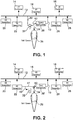
Figure 1 , a gaseoushydrogen product stream 10 is introduced into apipeline 12 for distribution of hydrogen tocustomers pipeline 12 by way of hydrogen generation facilities designated byreference numbers - Hydrogen for such pipeline may have a product purity specification of 99.99 mol% hydrogen in which the hydrogen contains less than 100 ppmv of nitrogen and argon, less than 1 ppmv of carbon monoxide and carbon dioxide, and less than 1 ppmv of methane, water vapor and hydrogen sulfide. Such a pipeline would therefore be capable of supplying high purity hydrogen under the aforesaid product purity specification. It also is possible that the product specification might have a lower product purity specification in which higher levels of impurities such as hydrogen sulfide would be tolerated.
- During periods of low demand by
customers hydrogen generation facilities gaseous hydrogen stream 30 is removed from apipeline 12 and compressed to 15,3 MPa (2200,psig) by acavern feed compressor 32 to produce acompressed hydrogen stream 34 that is stored within asalt cavern 36. When a hydrogen generation facility, such as that designated byreference number 20, is taken off-line for any reason or when demand for hydrogen bycustomers salt cavern 36 as acrude hydrogen stream 40 and purified withinpurification system 38. The purification ofcrude hydrogen stream 40 produceshydrogen product stream 10 which is reintroduced intopipeline 12.Hydrogen product stream 10 may have a pressure of between 4,2 MPa (600 psig) and 5,6 MPa (800 psig). - It is to be noted, that storage within
salt cavern 36 can introduce carbon dioxide into the hydrogen due to equilibrium with dissolved CO2. The brine has dissolved carbon dioxide which may off gas to the stored hydrogen. The stored gaseous hydrogen will be in contact with brine and therefore the level of moisture introduced into the stored hydrogen may be unacceptable. As mentioned above, carbon dioxide and water vapor may be the only significant impurities that could be effected by storage in thesalt cavern 36 and other impurities within the product purity specification would be unchanged by such storage. Hydrogen sulfide may be a significant impurity in the product purity specification. However, it is not completely understood whether salt cavern storage would have an effect on such an impurity. However, cavern brine is an aqueous solution containing salt ions, including sulfates and carbonates. The high partial pressure of hydrogen withinsalt cavern 36 could reduce sulfate ions to hydrogen sulfide or bacterial activity could generate H2S and therefore storage of gaseous hydrogen withinsalt cavern 36 could result in an unacceptable level of hydrogen sulfide to be returned topipeline 12. - As such, even though the hydrogen taken from
pipeline 10 may be at high purity, after storage, the possibility exists that carbon dioxide and water vapor levels will rise to unacceptable high levels with respect to the product purity specification. The same possibility exists for hydrogen sulfide when applicable. Other impurities within the product purity specification will remain unaffected by storage. - With reference to
Figure 2 ,salt cavern 36 and ahydrogen production facility 22 can be placed in close proximity to one another.Hydrogen generation facility 22 contains a hydrogen plant to produce a gaseous hydrogen product with a higher impurity level of at least carbon dioxide and water vapor than is required for the product purity specification and possibly also and hydrogen sulfide if applicable. Otherhydrogen generation facilities pipeline 12 under product purity specifications requiring specific concentrations of impurities such as carbon dioxide, water and hydrogen sulfide. As such, thehydrogen generation facilities - When excess hydrogen generation capacity exists, part of the gaseous hydrogen product, as a
gaseous hydrogen stream 41, is introduced into an onsite, final purification system 38' to acceptably reduce carbon dioxide, water vapor and hydrogen sulfide levels to meet the product purity specification. Other purification equipment would be included withinhydrogen production facility 22 to meet remaining component impurity requirements in the product specification. At such time, a remaining part of the gaseous hydrogen product, as agaseous hydrogen stream 42, would be compressed bycavern feed compressor 32 and stored withinsalt cavern 36 by way ofcompressed hydrogen stream 34. - When demand of gaseous hydrogen product is above the production capacity along
pipeline 12,crude hydrogen stream 40 is recovered from thesalt cavern 36 and is combined with agaseous hydrogen stream 41 to produce a combined stream that is sent to purification system 38' to formproduct stream 10. Hence, the purification system 38' functions both to purify the hydrogen from thehydrogen production facility 22, for instance, a steam methane reformer, and the hydrogen stored insalt cavern 36. As such, the hydrogen stored insalt cavern 36 is stored at low purity for later purification within purification system 38'. - The embodiment of
Fig. 2 allows dual use for final purification system 38' to function for bothhydrogen production facility 22 and hydrogen retrieved fromsalt cavern 36. This obviates the need to fabricate a separate purification facility dedicated tosalt cavern 36. A further modification to such embodiment would be to couplehydrogen production facility 22 andsalt cavern 36 to all purification used in connection withhydrogen production facility 22. - With reference to
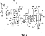
Figure 3 ,hydrogen purification system 38 is illustrated in a form that is capable of purifying gaseous hydrogen stored insalt cavern 36 from such contaminants as carbon dioxide, water vapor and hydrogen sulfide. Though the potential for hydrogen sulfide contamination from storage withinsalt cavern 36 is not known, it is seen as a safeguard from potential contamination that would result in an expensive loss of product if such contamination were to occur. The same design could be used for hydrogen purification system 38'. As may be appreciated, if hydrogen sulfide contamination were not in issue due to the product purity specification, hydrogen sulfide purification would be eliminated from the purification system. - Gaseous hydrogen stream 30 (shown in
Fig. 1 ) is removed frompipeline 12 through aconduit 46 having anisolation valve 48 to isolatehydrogen purification system 38 frompipeline 12 for maintenance purposes. In the following discussion, the control valves are normally in a closed position, cutting off the flow and can be remotely operated valves which are centrally and electronically controlled. - If hydrogen is to be stored,
control valve 50 is set in an open position. Acontrol valve 52 is also set in an open position to allow thegaseous hydrogen stream 30 to be fed to feedcompressor 32 andaftercooler 54.Aftercooler 54 is a known device consisting of a heat exchanger utilizing cooling water and a draft fan to remove the heat of compression from stream 30 (shown inFig. 1 ). The resultant compressed hydrogen stream 34 (shown inFig. 1 ) flows withinconduit 56 tosalt cavern 36.Control valves - As illustrated,
salt cavern 36 is of conventional design having abrine string 62 exhausting into a brine pond and a metal casing held in place by aconcrete lining 64. - After storage is complete, the aforementioned valves are returned to their normally closed condition. When production is to be supplemented with hydrogen stored in
salt cavern 36,control valve 60 is set in an open position to allow the supply of the hydrogen product stream 10 (shown inFig. 1 ) topipeline 12. The opening ofcontrol valve 60 allows crude hydrogen stream 40 (shown inFig. 1 ) to flow fromsalt cavern 36 throughconduit 68. Pressure is controlled withinconduit 68 bypressure transducers controller 74 that operatesproportional control valve 76. - The
crude hydrogen stream 40 then enters a coalescingfilter 78 of known design in which water is removed. Hydrogen sulfide is removed by a hydrogensulfide removal bed 80 which can utilize a zinc oxide catalytic adsorbent. In practice,bed 80 is never regenerated. It is simply replaced on a periodic maintenance schedule. Thecrude hydrogen stream 40 then enters a temperatureswing adsorption unit 82 as an intermediate product stream havingadsorbent beds Fig. 1 ) resulting from the purification of thecrude hydrogen stream 40 is then routed throughoutlet conduit 88.Pressure transducers controller 94 are used to control pressure withinoutlet conduit 88 through aproportional control valve 96. -
Hydrogen product stream 10 flows throughconduit 46 and back topipeline 12. As can be appreciated during this period of supply,control valve 52 is set in a closed position and controlvalve 50 is set in an open position. -
Adsorption beds regeneration conduit 98 is provided having aregeneration heater 100 which is controlled by atemperature transducer 102 and acontroller 104. A subsidiary hydrogen product stream, composed of part of the hydrogen product stream, is introduced to the off-line adsorption bed, eitherbed - The high temperature of the subsidiary hydrogen product stream causes desorption of carbon dioxide and water which is discharged from the bed being regenerated as a heated regeneration stream having increased concentrations of the desorbed carbon dioxide and water. Such heated regeneration stream is then cooled within a
regeneration cooler 106 which can be a water cooled heat exchanger in which a forced draft is produced by a draft fan. After the cooling of the heated regeneration stream, the resultant cooled stream is then sent to aregeneration separator 108 which is simply a pot to allow water produced by cooling within regeneration cooler 106 to discharge as astream 110. During regeneration,valve 112 is set in an open position to allow such stream to be compressed byfeed compressor 32 and cooled byaftercooler 54. Further,valve 58 is set in a closed position and avalve 114 is set in an open position to allow the resultant cooled, dried stream to combine with crude hydrogen stream flowing inconduit 68 for subsequent carbon dioxide and water removal. - As can be appreciated, the recirculation of the regeneration stream will eventually concentrate impurities within the purification system. In order to avoid this, at specific time periods,
valve 112 is set in a closed position andvalve 116 is reset in the open position to discharge the heated regeneration stream after having been cooled inregeneration cooler 106. The purging can be on a continual basis as well.Valve 112 could be open andvalve 116 could be partially opened. The degree to whichvalve 116 is open would be chosen to achieve a certain impurity level. A higher percentage of openness would lead to a lower impurity level (fewer impurities), and a lower percentage of openness would lead to a higher impurity level (more impurities). - As may be appreciated, it is possible to use other cycles for regeneration for adsorbent beds. For instance, the adsorbent beds could function on a pressure swing adsorption cycle. Moreover, membrane and cryogenic distillation devices could be used in place of adsorbent systems.
Claims (7)
- A method of storing and supplying a gaseous hydrogen product to a pipeline (12) under a product purity specification, said method comprising:compressing a hydrogen stream (30) made up of gaseous hydrogen to form a compressed hydrogen stream (34);introducing the compressed hydrogen stream (34) into a salt cavern (36) for storage of the gaseous hydrogen;recovering a crude hydrogen stream (40) from the salt cavern (36);purifying the crude hydrogen stream by sufficiently removing at least carbon dioxide and water vapor from the crude hydrogen stream (40) to at least in part produce a hydrogen product stream having an impurity level of the carbon dioxide and water vapor at or below the product purity specification; andsupplying the gaseous hydrogen product to the pipeline (12) by introducing said hydrogen product stream into said pipeline (12);wherein the hydrogen stream (30) to be stored is compressed to 15,3 MPa (2200 psig) and the hydrogen product stream (10) to be supplied to the pipeline is reduced in pressure to between 4,2 MPa (600 psig) and 5,6 MPa (800 psig).
- The method of claim 1, wherein:the hydrogen stream (30) is removed from the pipeline (12) and stored within the salt cavern (36) during periods of low demand for the hydrogen product; andthe hydrogen product stream (10) is introduced into the pipeline (12) during periods of high demand for the hydrogen product.
- The method of claim 1, wherein:the crude hydrogen stream (40) is purified by also sufficiently removing hydrogen sulfide;the product purity specification contains predetermined concentrations of hydrogen sulfide, water vapor and carbon dioxide;water in a liquid state and other contaminants are removed from the crude hydrogen stream (40) within a coalescing filter (78);the hydrogen sulfide, water vapor and the carbon dioxide are removed from the crude hydrogen stream (40) after the coalescing filter (78) by adsorption; andthe hydrogen sulfide is removed before the water vapor and the carbon dioxide.
- The method of claim 3, wherein:the hydrogen sulfide is removed within a hydrogen sulfide adsorption bed (80) to form an intermediate product stream; andthe intermediate product stream is introduced into a system of adsorbent beds (84, 86) configured to remove the carbon dioxide and water in an alternating fashion such that one bed is online producing the hydrogen product stream (10) while another bed is an off-line bed being regenerated through desorption.
- The method of claim 4, wherein:the system of adsorbent beds (84, 86) are operated in accordance with a temperature swing adsorption cycle;a subsidiary hydrogen product stream is divided out of the hydrogen product stream and is heated;the subsidiary hydrogen product stream is introduced into the off-line adsorbent bed, thereby to produce a regeneration stream containing desorbed impurities;water is separated from the regeneration stream; andafter water separation, the regeneration stream is compressed and recycled back to the coalescing filter (78).
- The method of claim 1, wherein the product purity specification of the hydrogen product stream (10) is 99.99 percent pure hydrogen containing less than 100 ppmv nitrogen and argon, less than 1 ppmv of carbon monoxide and carbon dioxide, less than 1 ppmv methane, less than 1 ppmv water, and less than 1 ppmv hydrogen sulfide.
- A method of producing, storing and supplying a gaseous hydrogen product to a pipeline (12) under a product purity specification, said method comprising:compressing a hydrogen stream (30) made up of gaseous hydrogen to form a compressed hydrogen stream (34);introducing the compressed hydrogen stream (34) into a salt cavern (36) for storage of the gaseous hydrogen;recovering a crude hydrogen stream (40) from the salt cavern (36);purifying the crude hydrogen stream by sufficiently removing at least carbon dioxide and water vapor from the crude hydrogen stream (40) to at least in part produce a hydrogen product stream having an impurity level of the carbon dioxide and water vapor at or below the product purity specification; andsupplying the gaseous hydrogen product to the pipeline (12) by introducing said hydrogen product stream into said pipeline (12);wherein the hydrogen stream (30) to be stored is compressed to 15,3 MPa (2200 psig) and the hydrogen product stream (10) to be supplied to the pipeline is reduced in pressure to between 4,2 MPa (600 psig) and 5,6 MPa (800 psig);wherein the gaseous hydrogen is produced by a hydrogen production facility having a hydrogen plant configured to produce the gaseous hydrogen with a higher impurity level of the carbon dioxide and water vapor than the product purity specification and by purification equipment configured to purify the gaseous hydrogen to directly produce the hydrogen product stream (10) and configured to purify the crude hydrogen stream (40) to produce the hydrogen product stream therefrom; andwhen demand for the gaseous hydrogen product is below a production capacity of the hydrogen plant, the hydrogen product stream (10) is formed by directly purifying part of the gaseous hydrogen without recovery of the crude hydrogen stream from the salt cavern (36) and utilizing a remaining part of the gaseous hydrogen as the hydrogen stream for compression and storage in the salt cavern (36); andwhen demand for the gaseous hydrogen product is above the production capacity of the hydrogen plant, the crude hydrogen stream (40) is recovered from the salt cavern (36) and purified to at least in part produce the product stream.
Applications Claiming Priority (2)
| Application Number | Priority Date | Filing Date | Title |
|---|---|---|---|
| US10/812,084 US7078011B2 (en) | 2004-03-30 | 2004-03-30 | Method of storing and supplying hydrogen to a pipeline |
| PCT/US2005/009353 WO2005100239A2 (en) | 2004-03-30 | 2005-03-22 | Hydrogen storage and supply method |
Publications (3)
| Publication Number | Publication Date |
|---|---|
| EP1735236A2 EP1735236A2 (en) | 2006-12-27 |
| EP1735236A4 EP1735236A4 (en) | 2012-02-15 |
| EP1735236B1 true EP1735236B1 (en) | 2018-02-14 |
Family
ID=35054520
Family Applications (1)
| Application Number | Title | Priority Date | Filing Date |
|---|---|---|---|
| EP05725984.8A Expired - Lifetime EP1735236B1 (en) | 2004-03-30 | 2005-03-22 | Hydrogen storage and supply method |
Country Status (3)
| Country | Link |
|---|---|
| US (1) | US7078011B2 (en) |
| EP (1) | EP1735236B1 (en) |
| WO (1) | WO2005100239A2 (en) |
Cited By (1)
| Publication number | Priority date | Publication date | Assignee | Title |
|---|---|---|---|---|
| WO2025250484A3 (en) * | 2024-05-28 | 2026-01-08 | Air Products And Chemicals, Inc. | Methods and systems for regenerating a temperature swing adsorption unit with pipeline hydrogen |
Families Citing this family (36)
| Publication number | Priority date | Publication date | Assignee | Title |
|---|---|---|---|---|
| US7637122B2 (en) * | 2001-05-04 | 2009-12-29 | Battelle Energy Alliance, Llc | Apparatus for the liquefaction of a gas and methods relating to same |
| US7591150B2 (en) | 2001-05-04 | 2009-09-22 | Battelle Energy Alliance, Llc | Apparatus for the liquefaction of natural gas and methods relating to same |
| US7594414B2 (en) | 2001-05-04 | 2009-09-29 | Battelle Energy Alliance, Llc | Apparatus for the liquefaction of natural gas and methods relating to same |
| US7451605B2 (en) * | 2001-12-19 | 2008-11-18 | Conversion Gas Imports, L.P. | LNG receiving terminal that primarily uses compensated salt cavern storage and method of use |
| DE602005024275D1 (en) * | 2004-08-02 | 2010-12-02 | Shell Int Research | METHOD FOR REMOVING THIOLS FROM AN INERTGAS STREAM |
| US20080233010A1 (en) * | 2007-03-19 | 2008-09-25 | Hydrogen Discoveries, Inc. | Testing Hydrogen Flux Through Solid and Liquid Barrier Materials |
| US8899074B2 (en) | 2009-10-22 | 2014-12-02 | Battelle Energy Alliance, Llc | Methods of natural gas liquefaction and natural gas liquefaction plants utilizing multiple and varying gas streams |
| US8555672B2 (en) | 2009-10-22 | 2013-10-15 | Battelle Energy Alliance, Llc | Complete liquefaction methods and apparatus |
| US8061413B2 (en) | 2007-09-13 | 2011-11-22 | Battelle Energy Alliance, Llc | Heat exchangers comprising at least one porous member positioned within a casing |
| US9217603B2 (en) | 2007-09-13 | 2015-12-22 | Battelle Energy Alliance, Llc | Heat exchanger and related methods |
| US9574713B2 (en) | 2007-09-13 | 2017-02-21 | Battelle Energy Alliance, Llc | Vaporization chambers and associated methods |
| US9254448B2 (en) | 2007-09-13 | 2016-02-09 | Battelle Energy Alliance, Llc | Sublimation systems and associated methods |
| WO2010078252A2 (en) * | 2008-12-30 | 2010-07-08 | Shell Oil Company | Method and system for supplying synthesis gas |
| US8425149B2 (en) | 2010-06-10 | 2013-04-23 | Praxair Technology, Inc. | Hydrogen storage method and system |
| US8950419B2 (en) | 2012-02-16 | 2015-02-10 | Praxair Technology, Inc. | Hydrogen supply method and system |
| US9284120B2 (en) | 2012-05-25 | 2016-03-15 | Praxair Technology, Inc. | Methods for storing hydrogen in a salt cavern with a permeation barrier |
| US8690476B2 (en) | 2012-05-25 | 2014-04-08 | Praxair Technology, Inc. | Method and system for storing hydrogen in a salt cavern with a permeation barrier |
| US10655911B2 (en) | 2012-06-20 | 2020-05-19 | Battelle Energy Alliance, Llc | Natural gas liquefaction employing independent refrigerant path |
| US20150323116A1 (en) * | 2014-05-06 | 2015-11-12 | Air Liquide Large Industries U.S. Lp | Method and apparatus for improving the integrity of a pipeline |
| US20150321859A1 (en) | 2014-05-06 | 2015-11-12 | Air Liquide Large Industries U.S. Lp | Method And Apparatus For Providing Over-Pressure Protection For An Underground Storage Cavern |
| US20150321846A1 (en) | 2014-05-08 | 2015-11-12 | Air Liquide Large Industries U.S. Lp | Hydrogen cavern pad gas management |
| US9718618B2 (en) | 2014-09-02 | 2017-08-01 | Praxair Technology, Inc. | System and method for treating hydrogen to be stored in a salt cavern and supplying therefrom |
| US9707603B2 (en) | 2014-09-30 | 2017-07-18 | Praxair Technology, Inc. | System and method for purging contaminants from a salt cavern |
| US20160138142A1 (en) | 2014-11-18 | 2016-05-19 | Air Liquide Large Industries U.S. Lp | Materials of construction for use in high pressure hydrogen storage in a salt cavern |
| US9573762B2 (en) | 2015-06-05 | 2017-02-21 | Air Liquide Large Industries U.S. Lp | Cavern pressure management |
| US9365349B1 (en) | 2015-11-17 | 2016-06-14 | Air Liquide Large Industries U.S. Lp | Use of multiple storage caverns for product impurity control |
| US9482654B1 (en) * | 2015-11-17 | 2016-11-01 | Air Liquide Large Industries U.S. Lp | Use of multiple storage caverns for product impurity control |
| US9950927B2 (en) | 2015-12-18 | 2018-04-24 | Praxair Technology, Inc. | Method of supplying hydrogen through an integrated supply system |
| CN107311108A (en) * | 2016-04-26 | 2017-11-03 | 内蒙古盾安光伏科技有限公司 | One kind avoids absorption column regeneration delay production technology |
| WO2022170188A1 (en) | 2021-02-08 | 2022-08-11 | TerraH2 LLC | Hydrogen production, storage and recovery |
| US11571652B2 (en) * | 2021-06-22 | 2023-02-07 | Praxair Technology, Inc. | Method of purifying hydrogen supplied from a storage cavern |
| CN113623001A (en) * | 2021-08-25 | 2021-11-09 | 中盐金坛盐化有限责任公司 | A method to reduce hydrogen consumption by microorganisms in underground salt caverns |
| US11655682B2 (en) * | 2021-09-23 | 2023-05-23 | Baker Hughes Oilfield Operations Llc | Fluid storage and production |
| US12320244B2 (en) | 2023-09-14 | 2025-06-03 | NeuVentus, LLC | Methods and systems for storing hydrogen in a salt cavern |
| US20250198567A1 (en) * | 2023-12-18 | 2025-06-19 | Air Products And Chemicals, Inc. | Methods and systems for underground gas storage |
| US20250320065A1 (en) * | 2024-04-11 | 2025-10-16 | King Fahd University Of Petroleum And Minerals | Hydrogen storage and withdrawal in a 3-phase (methane+carbon dioxide+nitrogen, brine and n-octane) gas reservoir |
Citations (7)
| Publication number | Priority date | Publication date | Assignee | Title |
|---|---|---|---|---|
| US4183369A (en) | 1977-11-04 | 1980-01-15 | Thomas Robert E | Method of transmitting hydrogen |
| US4365978A (en) | 1980-03-25 | 1982-12-28 | Shell Oil Company | Storage of liquid hydrocarbons in salt dome caverns |
| US4725381A (en) | 1984-03-02 | 1988-02-16 | Imperial Chemical Industries Plc | Hydrogen streams |
| EP0266731A2 (en) | 1986-11-03 | 1988-05-11 | Klaus-Dieter Dr.-Ing. Kaufmann | Method for feeding gas stocked in a cavern to the consumer mains, and installation for carrying out this method |
| WO1997046304A1 (en) | 1996-05-31 | 1997-12-11 | Filtan Filter-Anlagenbau Gmbh | Process and device for drying gas, especially natural gas |
| WO2002097321A1 (en) | 2001-05-25 | 2002-12-05 | Canatxx Energy, L.L.C. | Shallow depth, low pressure gas storage facilities and related methods of use |
| US6503299B2 (en) | 1999-11-03 | 2003-01-07 | Praxair Technology, Inc. | Pressure swing adsorption process for the production of hydrogen |
Family Cites Families (5)
| Publication number | Priority date | Publication date | Assignee | Title |
|---|---|---|---|---|
| US2878165A (en) | 1953-11-16 | 1959-03-17 | Phillips Petroleum Co | Ammonia storage and recovery system |
| US4025321A (en) * | 1975-09-30 | 1977-05-24 | Union Carbide Corporation | Purification of natural gas streams containing oxygen |
| US6511528B1 (en) * | 1999-03-26 | 2003-01-28 | Uop Llc | Purification of carbon dioxide |
| US6576138B2 (en) | 2000-12-14 | 2003-06-10 | Praxair Technology, Inc. | Method for purifying semiconductor gases |
| US6797039B2 (en) * | 2002-12-27 | 2004-09-28 | Dwain F. Spencer | Methods and systems for selectively separating CO2 from a multicomponent gaseous stream |
-
2004
- 2004-03-30 US US10/812,084 patent/US7078011B2/en not_active Expired - Lifetime
-
2005
- 2005-03-22 EP EP05725984.8A patent/EP1735236B1/en not_active Expired - Lifetime
- 2005-03-22 WO PCT/US2005/009353 patent/WO2005100239A2/en not_active Ceased
Patent Citations (7)
| Publication number | Priority date | Publication date | Assignee | Title |
|---|---|---|---|---|
| US4183369A (en) | 1977-11-04 | 1980-01-15 | Thomas Robert E | Method of transmitting hydrogen |
| US4365978A (en) | 1980-03-25 | 1982-12-28 | Shell Oil Company | Storage of liquid hydrocarbons in salt dome caverns |
| US4725381A (en) | 1984-03-02 | 1988-02-16 | Imperial Chemical Industries Plc | Hydrogen streams |
| EP0266731A2 (en) | 1986-11-03 | 1988-05-11 | Klaus-Dieter Dr.-Ing. Kaufmann | Method for feeding gas stocked in a cavern to the consumer mains, and installation for carrying out this method |
| WO1997046304A1 (en) | 1996-05-31 | 1997-12-11 | Filtan Filter-Anlagenbau Gmbh | Process and device for drying gas, especially natural gas |
| US6503299B2 (en) | 1999-11-03 | 2003-01-07 | Praxair Technology, Inc. | Pressure swing adsorption process for the production of hydrogen |
| WO2002097321A1 (en) | 2001-05-25 | 2002-12-05 | Canatxx Energy, L.L.C. | Shallow depth, low pressure gas storage facilities and related methods of use |
Non-Patent Citations (12)
| Title |
|---|
| "CGA G-5.3 Commodity spécification for Hydrogen", COMPRESSED GAS ASSOCIATION, INC., 1997, pages 1 - 13, XP055534394 |
| "Individual Compressed Gasses and Mixtures", HANDBOOK OF COMPRESSED GASES, 1990, pages 396 - 400, XP055534430 |
| "Nouvelles technologies pour l'exploration et l'exploitation des ressources de pétrole et de gaz", COMMISSION DES COMUNAUTÉS EUROPÉENES, 1986, pages 2, XP055534567 |
| FOH S ET AL.: "UNDERGROUND HYDROGEN STORAGE FINAL REPORT", BROOKHAVEN NATIONAL LABORATORY, December 1979 (1979-12-01), Upton, New York, US, pages 283PP, XP002664730 |
| HAEUSSINGER P ET AL: "HYDROGEN", 1 January 1989, ULLMANN'S ENCYCLOPEDIA OF INDUSTRIAL CHEMISTRY. HIGH PERFORMANCE FIBERS TO IMIDAZOLE AND DERIVATIVES; [ULLMANN'S ENCYCLOPEDIA OF INDUSTRIAL CHEMISTRY], WEINHEIM, VCH VERLAG, DE, PAGE(S) 297 - 441, XP001109477 * |
| KELLEY J H ET AL.: "STORAGE, TRANSMISSION AND DISTRIBUTION OF HYDROGEN", HYDROGEN ENERGY SYSTEM, PROCEEDINGS OF THE 2ND WORLD HYDROGEN ENERGY CONFERENCE, vol. 5, no. 1, 21 August 1978 (1978-08-21), Switzerland, pages 35 - 34, XP025578937 |
| KELLEY J H ET AL: "Storage, transmission and distribution of hydrogen", INTERNATIONAL JOURNAL OF HYDROGEN ENERGY, ELSEVIER SCIENCE PUBLISHERS B.V., BARKING, GB, vol. 5, no. 1, 1 January 1980 (1980-01-01), pages 35 - 54, XP025578937, ISSN: 0360-3199, [retrieved on 19800101], DOI: 10.1016/0360-3199(80)90113-5 * |
| KELLEY, J. H. ET AL.: "Storage, Transmission and Distribution of Hydrogen", INTERNATIONAL JOURNAL OF HYDROGEN ENERGY, vol. 5, no. 1, 1 January 1980 (1980-01-01), pages 35 - 54, XP025578937 |
| POTTIER J D ET AL.: "NATO ASI SERIES. SERIES E, APPLIED SCIENCES, Hydrogen energy system: production and utilization of hydrogen and future aspects, [proceedings of the NATO Advanced Study Institute on Hydrogen Energy System, Utilization of Hydrogen and Future Aspects]", MASS STORAGE OF HYDROGEN, vol. 295, January 1995 (1995-01-01), pages 167 - 179, XP008139790 |
| POTTIER, J. D. ET AL.: "Mass Storage of Hydrogen", PROCEEDINGS OF THE NATO ADVANCED STUDY INSTITUTE ON HYDROGEN ENERGY SYSTEM , UTILIZATION OF HYDROGEN AND FUTURE ASPECTS, vol. 295, 1995, pages 167 - 169, XP008139790 |
| TATCHELL JA: "Hydrogen in the Chemical Industry", AIM CONGRESS - HYDROGEN AND ITS PROSPECTS, 1976, pages 1 - 17, XP055534558 |
| WILLIAMSON ET AL., RECENT DEVELOPMENTS IN HYDROGEN TECHNOLOGY, vol. II, 1986, XP055534452 |
Cited By (1)
| Publication number | Priority date | Publication date | Assignee | Title |
|---|---|---|---|---|
| WO2025250484A3 (en) * | 2024-05-28 | 2026-01-08 | Air Products And Chemicals, Inc. | Methods and systems for regenerating a temperature swing adsorption unit with pipeline hydrogen |
Also Published As
| Publication number | Publication date |
|---|---|
| US20050220704A1 (en) | 2005-10-06 |
| WO2005100239A3 (en) | 2006-02-09 |
| EP1735236A2 (en) | 2006-12-27 |
| EP1735236A4 (en) | 2012-02-15 |
| WO2005100239A2 (en) | 2005-10-27 |
| US7078011B2 (en) | 2006-07-18 |
Similar Documents
| Publication | Publication Date | Title |
|---|---|---|
| EP1735236B1 (en) | Hydrogen storage and supply method | |
| AU2023226752B2 (en) | Systems and methods for short loop regeneration of gas dehydration units | |
| US5656557A (en) | Process for producing various gases for semiconductor production factories | |
| RU2460573C2 (en) | Improvements in methods of short-cycle adsorption | |
| US5226931A (en) | Process for supplying nitrogen from an on-site plant | |
| EP1602402B2 (en) | Off-gas feed method | |
| US11619443B2 (en) | Method for the production of air gases by the cryogenic separation of air with improved front end purification and air compression | |
| Benson et al. | Recovering hydrogen—And profits—From hydrogen-rich offgas | |
| CA2647909A1 (en) | Carbon dioxide and hydrogen production method from synthesis gas | |
| AU2022298318B2 (en) | Method of purifying hydrogen supplied from a storage cavern | |
| AU2009326953A1 (en) | Production of hydrogen from a reforming gas and simultaneous capture of CO2 co-product | |
| US20250128201A1 (en) | Method and system for upgrading biogas using psa | |
| CN102173392A (en) | Sulfur hexafluoride gas separation and purification device and purification method thereof | |
| CN102602899B (en) | Helium purification method and device | |
| CN103523822A (en) | A helium purifying method and a purifying device | |
| WO2004085941A1 (en) | Air separator | |
| KR100937769B1 (en) | Ultra-high purity nitrogen supplying apparatus | |
| CN102311103B (en) | Helium purifying method and purifying device thereof | |
| CN102311102B (en) | Helium purifying method and purifying device thereof | |
| JP7339929B2 (en) | Air separation unit, method for producing oxygen and/or nitrogen | |
| KR20130121088A (en) | Method and equipment for purifying a gas stream | |
| TWI865869B (en) | Fluid recovery process and apparatus for xenon and/or krypton recovery | |
| KR102003230B1 (en) | A method for addition producing higher purity oxygen and an apparatus thereof | |
| JPH06137755A (en) | Method and device for manufacturing boosted ultrahigh nitrogen | |
| CN210457461U (en) | Hydrogen purification device |
Legal Events
| Date | Code | Title | Description |
|---|---|---|---|
| PUAI | Public reference made under article 153(3) epc to a published international application that has entered the european phase |
Free format text: ORIGINAL CODE: 0009012 |
|
| 17P | Request for examination filed |
Effective date: 20061023 |
|
| AK | Designated contracting states |
Kind code of ref document: A2 Designated state(s): FR GB NL |
|
| DAX | Request for extension of the european patent (deleted) | ||
| RBV | Designated contracting states (corrected) |
Designated state(s): FR GB NL |
|
| RIC1 | Information provided on ipc code assigned before grant |
Ipc: E21B 41/00 20060101ALI20111201BHEP Ipc: B65G 5/00 20060101ALI20111201BHEP Ipc: C01B 3/50 20060101AFI20111201BHEP Ipc: C01B 3/56 20060101ALI20111201BHEP Ipc: B01D 53/04 20060101ALI20111201BHEP |
|
| A4 | Supplementary search report drawn up and despatched |
Effective date: 20120116 |
|
| RIC1 | Information provided on ipc code assigned before grant |
Ipc: B01D 53/04 20060101ALI20120109BHEP Ipc: C01B 3/50 20060101AFI20120109BHEP Ipc: C01B 3/56 20060101ALI20120109BHEP Ipc: E21B 41/00 20060101ALI20120109BHEP Ipc: B65G 5/00 20060101ALI20120109BHEP |
|
| 17Q | First examination report despatched |
Effective date: 20140124 |
|
| STAA | Information on the status of an ep patent application or granted ep patent |
Free format text: STATUS: EXAMINATION IS IN PROGRESS |
|
| RIC1 | Information provided on ipc code assigned before grant |
Ipc: C01B 3/50 20060101ALI20170406BHEP Ipc: B01D 53/26 20060101ALI20170406BHEP Ipc: B01D 53/04 20060101ALI20170406BHEP Ipc: C01B 3/56 20060101AFI20170406BHEP |
|
| GRAP | Despatch of communication of intention to grant a patent |
Free format text: ORIGINAL CODE: EPIDOSNIGR1 |
|
| STAA | Information on the status of an ep patent application or granted ep patent |
Free format text: STATUS: GRANT OF PATENT IS INTENDED |
|
| INTG | Intention to grant announced |
Effective date: 20170607 |
|
| GRAS | Grant fee paid |
Free format text: ORIGINAL CODE: EPIDOSNIGR3 |
|
| GRAA | (expected) grant |
Free format text: ORIGINAL CODE: 0009210 |
|
| STAA | Information on the status of an ep patent application or granted ep patent |
Free format text: STATUS: THE PATENT HAS BEEN GRANTED |
|
| AK | Designated contracting states |
Kind code of ref document: B1 Designated state(s): FR GB NL |
|
| REG | Reference to a national code |
Ref country code: GB Ref legal event code: FG4D |
|
| REG | Reference to a national code |
Ref country code: FR Ref legal event code: PLFP Year of fee payment: 14 |
|
| REG | Reference to a national code |
Ref country code: NL Ref legal event code: FP |
|
| PLBI | Opposition filed |
Free format text: ORIGINAL CODE: 0009260 |
|
| PLBI | Opposition filed |
Free format text: ORIGINAL CODE: 0009260 |
|
| PLAX | Notice of opposition and request to file observation + time limit sent |
Free format text: ORIGINAL CODE: EPIDOSNOBS2 |
|
| 26 | Opposition filed |
Opponent name: L'AIR LIQUIDE, SOCIETE ANONYME POUR L'ETUDE ET L'E Effective date: 20181112 |
|
| 26 | Opposition filed |
Opponent name: DEEP.KBB GMBH Effective date: 20181113 |
|
| GBPC | Gb: european patent ceased through non-payment of renewal fee |
Effective date: 20180514 |
|
| PLBB | Reply of patent proprietor to notice(s) of opposition received |
Free format text: ORIGINAL CODE: EPIDOSNOBS3 |
|
| PG25 | Lapsed in a contracting state [announced via postgrant information from national office to epo] |
Ref country code: GB Free format text: LAPSE BECAUSE OF NON-PAYMENT OF DUE FEES Effective date: 20180514 |
|
| RAP2 | Party data changed (patent owner data changed or rights of a patent transferred) |
Owner name: PRAXAIR TECHNOLOGY, INC. |
|
| PLAB | Opposition data, opponent's data or that of the opponent's representative modified |
Free format text: ORIGINAL CODE: 0009299OPPO |
|
| R26 | Opposition filed (corrected) |
Opponent name: L'AIR LIQUIDE, SOCIETE ANONYME POUR L'ETUDE ET L'EXPLOITATION DES PROCEDES GEORGES CLAUDE Effective date: 20181112 |
|
| PLAO | Information deleted related to despatch of communication that opposition is rejected |
Free format text: ORIGINAL CODE: EPIDOSDREJ1 |
|
| PLCK | Communication despatched that opposition was rejected |
Free format text: ORIGINAL CODE: EPIDOSNREJ1 |
|
| PLCK | Communication despatched that opposition was rejected |
Free format text: ORIGINAL CODE: EPIDOSNREJ1 |
|
| PLBN | Opposition rejected |
Free format text: ORIGINAL CODE: 0009273 |
|
| STAA | Information on the status of an ep patent application or granted ep patent |
Free format text: STATUS: OPPOSITION REJECTED |
|
| 27O | Opposition rejected |
Effective date: 20210420 |
|
| PGFP | Annual fee paid to national office [announced via postgrant information from national office to epo] |
Ref country code: NL Payment date: 20240220 Year of fee payment: 20 |
|
| PGFP | Annual fee paid to national office [announced via postgrant information from national office to epo] |
Ref country code: FR Payment date: 20240221 Year of fee payment: 20 |
|
| REG | Reference to a national code |
Ref country code: NL Ref legal event code: MK Effective date: 20250321 |