EP1735030B1 - Dual cylinder vacuum pump for medical aspiration system - Google Patents
Dual cylinder vacuum pump for medical aspiration system Download PDFInfo
- Publication number
- EP1735030B1 EP1735030B1 EP05729894.5A EP05729894A EP1735030B1 EP 1735030 B1 EP1735030 B1 EP 1735030B1 EP 05729894 A EP05729894 A EP 05729894A EP 1735030 B1 EP1735030 B1 EP 1735030B1
- Authority
- EP
- European Patent Office
- Prior art keywords
- cylinder
- pump
- valve
- plunger
- fluid communication
- Prior art date
- Legal status (The legal status is an assumption and is not a legal conclusion. Google has not performed a legal analysis and makes no representation as to the accuracy of the status listed.)
- Active
Links
- 230000009977 dual effect Effects 0.000 title description 3
- 239000012530 fluid Substances 0.000 claims description 35
- 238000004891 communication Methods 0.000 claims description 15
- 238000000034 method Methods 0.000 description 7
- 230000002572 peristaltic effect Effects 0.000 description 5
- IJGRMHOSHXDMSA-UHFFFAOYSA-N Atomic nitrogen Chemical compound N#N IJGRMHOSHXDMSA-UHFFFAOYSA-N 0.000 description 3
- 238000003973 irrigation Methods 0.000 description 3
- 230000002262 irrigation Effects 0.000 description 3
- 210000002159 anterior chamber Anatomy 0.000 description 2
- 230000000712 assembly Effects 0.000 description 2
- 238000000429 assembly Methods 0.000 description 2
- 210000001525 retina Anatomy 0.000 description 2
- 208000002177 Cataract Diseases 0.000 description 1
- 238000010276 construction Methods 0.000 description 1
- 229910001873 dinitrogen Inorganic materials 0.000 description 1
- 238000007599 discharging Methods 0.000 description 1
- 239000007789 gas Substances 0.000 description 1
- 238000012986 modification Methods 0.000 description 1
- 230000004048 modification Effects 0.000 description 1
- 229910052757 nitrogen Inorganic materials 0.000 description 1
- 230000002207 retinal effect Effects 0.000 description 1
Images

Classifications
-
- A—HUMAN NECESSITIES
- A61—MEDICAL OR VETERINARY SCIENCE; HYGIENE
- A61M—DEVICES FOR INTRODUCING MEDIA INTO, OR ONTO, THE BODY; DEVICES FOR TRANSDUCING BODY MEDIA OR FOR TAKING MEDIA FROM THE BODY; DEVICES FOR PRODUCING OR ENDING SLEEP OR STUPOR
- A61M1/00—Suction or pumping devices for medical purposes; Devices for carrying-off, for treatment of, or for carrying-over, body-liquids; Drainage systems
- A61M1/80—Suction pumps
- A61M1/81—Piston pumps, e.g. syringes
-
- A—HUMAN NECESSITIES
- A61—MEDICAL OR VETERINARY SCIENCE; HYGIENE
- A61M—DEVICES FOR INTRODUCING MEDIA INTO, OR ONTO, THE BODY; DEVICES FOR TRANSDUCING BODY MEDIA OR FOR TAKING MEDIA FROM THE BODY; DEVICES FOR PRODUCING OR ENDING SLEEP OR STUPOR
- A61M1/00—Suction or pumping devices for medical purposes; Devices for carrying-off, for treatment of, or for carrying-over, body-liquids; Drainage systems
- A61M1/71—Suction drainage systems
- A61M1/77—Suction-irrigation systems
- A61M1/772—Suction-irrigation systems operating alternately
Definitions
- the present invention relates to a medical aspiration system as defined by the claims.
- Ophthalmic procedures are typically performed with instruments that have a tip located at the distal end of a handpiece.
- the handpiece is held by a surgeon who inserts the tip into the inner ocular chamber of an eye.
- the surgeon may remove a cataracteous lens, or reattach a retina with the instrument.
- Document US 2002 151 835 discloses a medical aspiration system
- irrigation fluid is introduced into the eye to maintain the ocular pressure of the anterior chamber.
- the handpiece tip is coupled to an aspiration system that pulls the irrigation fluid and possibly tissue out of the anterior chamber.
- the tissue and irrigation fluid flow through an inner channel in the tip.
- the aspiration system includes a pump coupled to an aspiration tube.
- the aspiration tube is connected to an outlet port of the handpiece.
- Most aspiration pumps are of the peristaltic type because the pump behavior is predictable.
- a peristaltic pump essentially pushes the air/fluid within the aspiration tube to create a vacuum pressure within the tube.
- the operation of a peristaltic pump creates surges in the pressure within the system. Pressure surges can be undesirable when performing delicate procedures such as retinal reattachment.
- Venturi pumps do not creates pressure surges and are thus typically used in delicate ophthalmic procedures.
- Commercially available venturi pumps require a tank of compressed nitrogen gas. It is generally undesirable to have a pressurized gas tank in an operating environment. Additionally, venturi pumps are energy inefficient in creating a vacuum.
- a pump for a medical aspiration system includes a housing with an input port, an output port, a first cylinder and a second cylinder.
- a motor assembly of the pump moves a first plunger within the first cylinder and a second plunger within a second cylinder.
- the pump includes valve assemblies that control fluid communication between the input/output ports and the cylinders.
- a dual cylinder pump that is used to create a vacuum in an aspiration tube of a medical system.
- the pump includes a first plunger that moves within a first cylinder and a second plunger that moves within a second cylinder. Movement of the plungers is controlled by a motor assembly.
- the pump includes valves that control the flow of fluid into and out of the cylinders so that one cylinder is pulling fluid from the aspiration tube while the other cylinder is discharging fluid. In this manner the pump is continuously pulling vacuum, thereby preventing vacuum surges found in peristaltic pumps of the prior art. Additionally, the pump is relatively energy efficient and does not require a separate nitrogen tank as required by commercially available venturi pumps of the prior art.
- the pump can be constructed as a cartridge that can be removed and disposed.
- Figure 1 shows an embodiment of a medical system 10 of the present invention.
- the system 10 may be used by a surgeon to perform ophthalmic medical procedures such as cataract lens removal, or retina reattachment.
- the system 10 may include an instrument 12 that is coupled to an aspiration system 14.
- the instrument 12 may include a tip 16 that extends from a handpiece 18 and can be held by a surgeon.
- the tip 16 can be inserted into the eye of a patient.
- the aspiration system 14 may include an aspiration tube(s) 20 that is coupled to the instrument 12.
- the aspiration tube 20 is connected to a vacuum pump 22 and a collection canister 24.
- the vacuum pump 22 creates a vacuum pressure within the aspiration tube 20 and a flow of fluid from the instrument 12 to the canister 24.
- the aspiration system 14 can pull emulsified tissue and fluid from the instrument 12 and into the canister 29.
- the system 10 may include a controller 26 that is connected to the instrument 12 and the vacuum pump 22.
- the system 10 may further have a control device such as a foot pedal 28 that is connected to the controller 26.
- the surgeon can control the instrument 12 and/or the pump 22 thru the foot pedal 28.
- the controller 26 may include a processor, memory, etc. (not shown) that can operate the pump 22 in synchronization with the instrument 12.
- the foot pedal 28 is shown as being connected to the controller 26, the foot pedal 28 may be connected directly to the pump 22 and/or instrument 12.
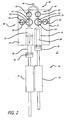
- FIG. 2 shows an embodiment of the vacuum pump 22.
- the pump 22 may include a housing 30 that has a first cylinder 32 and a second cylinder 34.
- the housing 30 also includes an input port 36 and an output port 38.
- the input port 36 includes channels 40 and 42 in fluid communication with the first 32 and second cylinders 34, respectively.
- the pump 22 may have a first valve assembly 44 that controls the flow of fluid between the cylinders 32 and 34 and a manifold tube 46.
- the manifold tube 46 is connected to the aspiration tube 20 of the aspiration system 14.
- the first valve assembly 44 may include a first input valve 48 that controls the flow of fluid into the first cylinder 32 and a second input valve 50 that controls the flow of fluid into the second cylinder 34.
- the pump 22 may further have a second valve assembly 52 that controls the flow of fluid between the cylinders 32 and 34 and outlet lines 54 and 56 of the output port.
- the second valve assembly 52 may include a first output valve 58 that controls the flow of fluid from the first cylinder 32 and a second output valve 60 that controls the flow of fluid from the second cylinder 34.
- the valves 48, 50, 58 and 60 may be controlled actuators or motors that are connected to and controlled by the controller 26 shown in Fig. 1 .
- the pump 22 may include pressure transducers 62 and 64 that sense the pressure within the first 32 and second 34 cylinders, respectively.
- the pressure transducers 62 and 64 can be connected to the controller 26 shown in Fig. 1 , and provide pressure feedback information that can be used in a feedback control loop of the pump 22.
- the pump 22 includes a first plunger 66 that moves within the first cylinder 32 and a second plunger 68 that moves within the second cylinder 34.
- the plungers 66 and 68 are moved by a motor assembly 70.
- the motor assembly 70 may include a first motor 72 that moves the first plunger 66 and a second motor 74 that moves the second plunger 68.
- the motors 72 and 74 may move the plungers 66 and 68 out of phase relative to each other.
- the plungers 66 and 68 may move 180 degrees out of phase relative to each other.
- the motors 72 and 74 may be connected to the controller 26 which controls the timing and phase of the plungers 66 and 68. Although two motors are shown and described, it is to be understood that the plungers could be coupled to a single motor.
- the motors 72 and 74 may be attached to the plungers 66 and 68 by couplers 76 and 78.
- the couplers 76 and 68 may be of the quick disconnect type so that the plungers 66 and 68, and housing 30 can be detached from the motor assembly 70. This allows the housing 30 and plungers 66 and 68 to be packaged as a cartridge that can be detached after a medical procedure.
- the plungers 66 and 68 may be of the syringe type that can be readily discarded and replaced.
- the housing 30 can be sterilized for reuse in the system 10.
- the valve actuators and pressure transducers may also be attached to the housing 30 in a sealed and readily detachable manner so that these components do not have to be sterilized after each procedure.
- the controller 26 may control the motors 72 and 74 and the valve assemblies 44 and 52 in the following manner.
- the first input valve 48 may be opened to provide fluid communication between the manifold tube 46 and the first cylinder 32.
- the second input valve 50 is closed.
- the first motor 72 may pull the first plunger 66 in a direction indicated by the arrow. Movement of the plunger 66 pulls fluid into the first cylinder 32.
- the first input valve 48 When the first plunger 66 reaches an end of travel the first input valve 48 is closed and the second input valve 50 is opened.
- the second motor 74 then pulls the second plunger 68 to draw fluid into the second cylinder 34.
- the first motor 72 pushes the first plunger 66.
- the first output valve 58 is opened so that the fluid within the first cylinder 32 is pushed out of the pump 22.
- the motors and valves are operated so that one of the cylinders is pulling in fluid while the other cylinder is pushing out fluid. In this manner a continuous vacuum is created in the aspiration tube. There are not sudden surges as found in prior art peristaltic pumps.
- the second plunger 68 may begin to pull a vacuum in cylinder 34 as the first plunger 66 nears the end of travel in cylinder 32.
- Valve 50 may be closed during movement of the second plunger until the transducers 62 and 64 sense the same pressure wherein valve 50 is opened and valve 48 is closed.
- the pump 22 may have other value arrangements.
- the pump 22 may have a single four-way valve.
Description
- This application claims priority to provisional application No.
556,963 filed on March 26, 2004 . - The present invention relates to a medical aspiration system as defined by the claims.
- Ophthalmic procedures are typically performed with instruments that have a tip located at the distal end of a handpiece. The handpiece is held by a surgeon who inserts the tip into the inner ocular chamber of an eye. By way of example, the surgeon may remove a cataracteous lens, or reattach a retina with the instrument. Document
US 2002 151 835 discloses a medical aspiration system - During a procedure, irrigation fluid is introduced into the eye to maintain the ocular pressure of the anterior chamber. The handpiece tip is coupled to an aspiration system that pulls the irrigation fluid and possibly tissue out of the anterior chamber. The tissue and irrigation fluid flow through an inner channel in the tip.
- The aspiration system includes a pump coupled to an aspiration tube. The aspiration tube is connected to an outlet port of the handpiece. Most aspiration pumps are of the peristaltic type because the pump behavior is predictable. A peristaltic pump essentially pushes the air/fluid within the aspiration tube to create a vacuum pressure within the tube. The operation of a peristaltic pump creates surges in the pressure within the system. Pressure surges can be undesirable when performing delicate procedures such as retinal reattachment.
- Some aspiration systems contain a venturi type pump. Venturi pumps do not creates pressure surges and are thus typically used in delicate ophthalmic procedures. Commercially available venturi pumps require a tank of compressed nitrogen gas. It is generally undesirable to have a pressurized gas tank in an operating environment. Additionally, venturi pumps are energy inefficient in creating a vacuum.
- A pump for a medical aspiration system. The pump includes a housing with an input port, an output port, a first cylinder and a second cylinder. A motor assembly of the pump moves a first plunger within the first cylinder and a second plunger within a second cylinder. The pump includes valve assemblies that control fluid communication between the input/output ports and the cylinders.
-
-
Figure 1 is a schematic of an embodiment of a medical system; -
Figure 2 is an illustration of a dual cylinder pump of the medical system. - Disclosed is a dual cylinder pump that is used to create a vacuum in an aspiration tube of a medical system. The pump includes a first plunger that moves within a first cylinder and a second plunger that moves within a second cylinder. Movement of the plungers is controlled by a motor assembly. The pump includes valves that control the flow of fluid into and out of the cylinders so that one cylinder is pulling fluid from the aspiration tube while the other cylinder is discharging fluid. In this manner the pump is continuously pulling vacuum, thereby preventing vacuum surges found in peristaltic pumps of the prior art. Additionally, the pump is relatively energy efficient and does not require a separate nitrogen tank as required by commercially available venturi pumps of the prior art. The pump can be constructed as a cartridge that can be removed and disposed.
- Referring to the drawings more particularly by reference numbers,
Figure 1 shows an embodiment of amedical system 10 of the present invention. Thesystem 10 may be used by a surgeon to perform ophthalmic medical procedures such as cataract lens removal, or retina reattachment. - The
system 10 may include aninstrument 12 that is coupled to anaspiration system 14. Theinstrument 12 may include atip 16 that extends from ahandpiece 18 and can be held by a surgeon. Thetip 16 can be inserted into the eye of a patient. - The
aspiration system 14 may include an aspiration tube(s) 20 that is coupled to theinstrument 12. Theaspiration tube 20 is connected to avacuum pump 22 and acollection canister 24. Thevacuum pump 22 creates a vacuum pressure within theaspiration tube 20 and a flow of fluid from theinstrument 12 to thecanister 24. Theaspiration system 14 can pull emulsified tissue and fluid from theinstrument 12 and into the canister 29. - The
system 10 may include acontroller 26 that is connected to theinstrument 12 and thevacuum pump 22. Thesystem 10 may further have a control device such as afoot pedal 28 that is connected to thecontroller 26. The surgeon can control theinstrument 12 and/or thepump 22 thru thefoot pedal 28. Thecontroller 26 may include a processor, memory, etc. (not shown) that can operate thepump 22 in synchronization with theinstrument 12. Although thefoot pedal 28 is shown as being connected to thecontroller 26, thefoot pedal 28 may be connected directly to thepump 22 and/orinstrument 12. -
Figure 2 shows an embodiment of thevacuum pump 22. Thepump 22 may include ahousing 30 that has afirst cylinder 32 and asecond cylinder 34. Thehousing 30 also includes aninput port 36 and anoutput port 38. Theinput port 36 includeschannels second cylinders 34, respectively. - The
pump 22 may have afirst valve assembly 44 that controls the flow of fluid between thecylinders manifold tube 46. Themanifold tube 46 is connected to theaspiration tube 20 of theaspiration system 14. Thefirst valve assembly 44 may include afirst input valve 48 that controls the flow of fluid into thefirst cylinder 32 and asecond input valve 50 that controls the flow of fluid into thesecond cylinder 34. - The
pump 22 may further have asecond valve assembly 52 that controls the flow of fluid between thecylinders outlet lines second valve assembly 52 may include afirst output valve 58 that controls the flow of fluid from thefirst cylinder 32 and asecond output valve 60 that controls the flow of fluid from thesecond cylinder 34. Thevalves controller 26 shown inFig. 1 . - The
pump 22 may includepressure transducers controller 26 shown inFig. 1 , and provide pressure feedback information that can be used in a feedback control loop of thepump 22. - The
pump 22 includes afirst plunger 66 that moves within thefirst cylinder 32 and asecond plunger 68 that moves within thesecond cylinder 34. Theplungers motor assembly 70. Themotor assembly 70 may include afirst motor 72 that moves thefirst plunger 66 and asecond motor 74 that moves thesecond plunger 68. Themotors plungers plungers motors controller 26 which controls the timing and phase of theplungers - The
motors plungers couplers couplers plungers housing 30 can be detached from themotor assembly 70. This allows thehousing 30 andplungers plungers housing 30 can be sterilized for reuse in thesystem 10. The valve actuators and pressure transducers may also be attached to thehousing 30 in a sealed and readily detachable manner so that these components do not have to be sterilized after each procedure. - The
controller 26 may control themotors valve assemblies first input valve 48 may be opened to provide fluid communication between themanifold tube 46 and thefirst cylinder 32. Thesecond input valve 50 is closed. Thefirst motor 72 may pull thefirst plunger 66 in a direction indicated by the arrow. Movement of theplunger 66 pulls fluid into thefirst cylinder 32. - When the
first plunger 66 reaches an end of travel thefirst input valve 48 is closed and thesecond input valve 50 is opened. Thesecond motor 74 then pulls thesecond plunger 68 to draw fluid into thesecond cylinder 34. During this second plunger movement thefirst motor 72 pushes thefirst plunger 66. Thefirst output valve 58 is opened so that the fluid within thefirst cylinder 32 is pushed out of thepump 22. The motors and valves are operated so that one of the cylinders is pulling in fluid while the other cylinder is pushing out fluid. In this manner a continuous vacuum is created in the aspiration tube. There are not sudden surges as found in prior art peristaltic pumps. - To maintain a continuous vacuum level, the
second plunger 68 may begin to pull a vacuum incylinder 34 as thefirst plunger 66 nears the end of travel incylinder 32.Valve 50 may be closed during movement of the second plunger until thetransducers valve 50 is opened andvalve 48 is closed. - While certain exemplary embodiments have been described and shown in the accompanying drawings, it is to be understood that such embodiments are merely illustrative of and not restrictive on the broad invention, and that this invention not be limited to the specific constructions and arrangements shown and described, since various other modifications may occur to those ordinarily skilled in the art.
- For example, although
multiple values pump 22 may have other value arrangements. By way of example thepump 22 may have a single four-way valve.
Claims (13)
- A medical system (10), comprising:an instrument (12);an aspiration tube (20) coupled to said instrument (12);a pump (22) ; anda control device (26) coupled to said pump (22),characterized in thatsaid pump (22) includes;a housing (30) that has an input port (36) coupled to said aspiration tube (20), an output port (38) coupled to said aspiration tube (20), a first cylinder (32) and a second cylinder (34);a first plunger (66) that moves within said first cylinder (32);a second plunger (68) that moves within said second cylinder (34);a motor assembly (70) that moves said first and second plungers (66, 68) within said first and second cylinders (32, 34), respectively; anda valve assembly (52) that controls fluid communication between said first and second cylinders (32, 34), and said input and output ports (36, 38).
- The system (10) of claim 1, wherein said motor assembly (70) includes a first motor (72) connected to said first plunger (66) by a first coupler (76) and a second motor (74) connected to said second plunger (68) by a second coupler (78).
- The system (10) of claim 1, wherein said first and second plungers (66, 68) move out of phase relative to each other.
- The system (10) of claim 1, wherein at least one valve (48, 50, 58, 60) of the valve assembly (70) is adapted to be switched to create fluid communication between an input port (36) of the housing (30) and the first and second cylinders (32, 34) and a fluid communication between an output port (54, 56) of the housing (30) and the first and second cylinders (32, 34), so that movement of the first and second plungers (66, 68) create a vacuum within an aspiration tube (20) coupled to the input port (36).
- The system (10) of claim 1, wherein said valve assembly (52) includes a first input valve (48) that controls fluid communication between said input port (36) and said first cylinder (32) and a second input valve (42) that controls fluid communication between input port (36) and said second cylinder (34).
- The system (10) of claim 1, wherein said valve assembly (52) includes a first output valve (58) that controls fluid communication between said first cylinder (32) and said output port (54) and a second output valve (60) that controls fluid communication between said second cylinder and said output port (52).
- The system (10) of claim 1, wherein said control device (26) includes a foot pedal (28).
- The system (10) of claim 7, further comprising a controller (26) coupled to said foot pedal (28) and said pump (22).
- Use of a pump (22) in a medical aspiration system (10), wherein the pump (22) comprises:a housing (30) that has an input port (36), an output port (54, 56), a first cylinder (32) and a second cylinder (34);a first plunger (66) that moves within said first cylinder (32);a second plunger (68) that moves within said second cylinder (34);a motor assembly (70) that moves said first and second plungers (66, 68) within said first and second cylinders (32, 34), respectively; and,a valve assembly (52) that controls fluid communication between said first and second cylinders (32, 34), and said input and output ports (36, 38).
- Use of the pump (22) according to claim 9, wherein said motor assembly (70) includes a first motor (72) connected to said first plunger (66) by a first coupler (76) and a second motor (74) connected to said second plunger (68) by a second coupler (78).
- Use of the pump (22) according to claim 9, wherein said first and second plungers (66, 68) move out of phase relative to each other.
- Use of the pump (22) according to claim 9, wherein said valve assembly (70) includes a first input valve (48) that controls fluid communication between said input port (36) and said first cylinder (32) and a second input valve (50) that controls fluid communication between input port (36) and said second cylinder (34).
- Use of the pump (22) according to claim 9, wherein said valve assembly (70) includes a first output valve (58) that controls fluid communication between said first cylinder (32) and said output port (54) and a second output valve (60) that controls fluid communication between said second cylinder (34) and said output port (56).
Priority Applications (1)
| Application Number | Priority Date | Filing Date | Title |
|---|---|---|---|
| EP16183264.7A EP3112680B1 (en) | 2004-03-26 | 2005-03-24 | Dual cylinder vacuum pump for medical aspiration system |
Applications Claiming Priority (3)
| Application Number | Priority Date | Filing Date | Title |
|---|---|---|---|
| US55696304P | 2004-03-26 | 2004-03-26 | |
| US11/088,318 US20050234394A1 (en) | 2004-03-26 | 2005-03-23 | Dual cylinder vacuum pump for medical aspiration system |
| PCT/US2005/009666 WO2005097229A2 (en) | 2004-03-26 | 2005-03-24 | Dual cylinder vacuum pump for medical aspiration system |
Related Child Applications (1)
| Application Number | Title | Priority Date | Filing Date |
|---|---|---|---|
| EP16183264.7A Division EP3112680B1 (en) | 2004-03-26 | 2005-03-24 | Dual cylinder vacuum pump for medical aspiration system |
Publications (3)
| Publication Number | Publication Date |
|---|---|
| EP1735030A2 EP1735030A2 (en) | 2006-12-27 |
| EP1735030A4 EP1735030A4 (en) | 2013-12-18 |
| EP1735030B1 true EP1735030B1 (en) | 2016-08-17 |
Family
ID=35097212
Family Applications (2)
| Application Number | Title | Priority Date | Filing Date |
|---|---|---|---|
| EP05729894.5A Active EP1735030B1 (en) | 2004-03-26 | 2005-03-24 | Dual cylinder vacuum pump for medical aspiration system |
| EP16183264.7A Active EP3112680B1 (en) | 2004-03-26 | 2005-03-24 | Dual cylinder vacuum pump for medical aspiration system |
Family Applications After (1)
| Application Number | Title | Priority Date | Filing Date |
|---|---|---|---|
| EP16183264.7A Active EP3112680B1 (en) | 2004-03-26 | 2005-03-24 | Dual cylinder vacuum pump for medical aspiration system |
Country Status (6)
| Country | Link |
|---|---|
| US (2) | US20050234394A1 (en) |
| EP (2) | EP1735030B1 (en) |
| JP (1) | JP5191229B2 (en) |
| AU (1) | AU2005231690B2 (en) |
| CA (1) | CA2559205C (en) |
| WO (1) | WO2005097229A2 (en) |
Cited By (7)
| Publication number | Priority date | Publication date | Assignee | Title |
|---|---|---|---|---|
| US10624785B2 (en) | 2016-01-30 | 2020-04-21 | Carl Zeiss Meditec Cataract Technology Inc. | Devices and methods for ocular surgery |
| US11051981B2 (en) | 2017-05-04 | 2021-07-06 | Carl Zeiss Meditec Cataract Technology Inc. | Devices and methods for ocular surgery |
| US11241335B2 (en) | 2019-02-01 | 2022-02-08 | Carl Zeiss Meditec Cataract Technology Inc. | Ophthalmic cutting instruments having integrated aspiration pump |
| EP4006339A1 (en) | 2020-11-27 | 2022-06-01 | Erbe Elektromedizin GmbH | Pump unit for medical purposes |
| US11638660B2 (en) | 2018-06-05 | 2023-05-02 | Carl Zeiss Meditec Cataract Technology Inc. | Ophthalmic microsurgical tools, systems, and methods of use |
| US11730625B2 (en) | 2019-05-17 | 2023-08-22 | Carl Zeiss Meditec Cataract Technology Inc. | Ophthalmic cutting instruments having integrated aspiration pump |
| US11801163B2 (en) | 2019-06-07 | 2023-10-31 | Carl Zeiss Meditec Cataract Technology Inc. | Multi-stage trigger for ophthalmology cutting tool |
Families Citing this family (11)
| Publication number | Priority date | Publication date | Assignee | Title |
|---|---|---|---|---|
| ITTO20060876A1 (en) * | 2006-12-11 | 2008-06-12 | Vhit Spa | VACUUM PUMP WITH DEVICE FOR HIS DEACTIVATION |
| US9999710B2 (en) | 2009-01-07 | 2018-06-19 | Med-Logics, Inc. | Tissue removal devices, systems and methods |
| CA2750407C (en) * | 2009-01-07 | 2018-12-04 | Enlighten Technologies, Inc. | Tissue removal devices |
| WO2014176121A1 (en) | 2013-04-26 | 2014-10-30 | Medlogics Inc. | Tissue removal devices, systems and methods |
| WO2013043881A1 (en) | 2011-09-21 | 2013-03-28 | Medrad. Inc. | Continuous multi-fluid pump device, drive and actuating system and method |
| CN104635776A (en) * | 2013-11-13 | 2015-05-20 | 中国科学院沈阳科学仪器股份有限公司 | Wide-range pressure control system and method applied to vacuum equipment |
| US10537471B2 (en) * | 2014-04-17 | 2020-01-21 | Novartis Ag | Hydraulic pump for ophthalmic surgery |
| KR101762231B1 (en) * | 2014-12-05 | 2017-07-27 | 백정흔 | Medical fluid supplying apparatus |
| US10507319B2 (en) | 2015-01-09 | 2019-12-17 | Bayer Healthcare Llc | Multiple fluid delivery system with multi-use disposable set and features thereof |
| CN105311697B (en) * | 2015-11-04 | 2019-02-15 | 中南大学湘雅三医院 | A kind of laparoscope suction device |
| KR101706557B1 (en) * | 2016-05-09 | 2017-02-16 | (주)빅하우스 | Continuous reciprocating disinfectant feeder for pipelines |
Family Cites Families (32)
| Publication number | Priority date | Publication date | Assignee | Title |
|---|---|---|---|---|
| US805530A (en) * | 1905-03-27 | 1905-11-28 | John B Davis | Oil-pump. |
| US1267088A (en) * | 1917-03-08 | 1918-05-21 | Major A Lane | Automobile-tire pump. |
| FR1575563A (en) * | 1968-01-26 | 1969-07-25 | ||
| US3637330A (en) * | 1969-11-21 | 1972-01-25 | Aqua Chem Inc | Multichamber tubular diaphragm pump |
| US3981620A (en) * | 1972-03-06 | 1976-09-21 | Waters Associates, Inc. | Pumping apparatus |
| US4127360A (en) * | 1976-12-16 | 1978-11-28 | Carpenter Clarence W | Bumpless pump apparatus adjustable to meet slave system needs |
| US4273261A (en) * | 1979-04-04 | 1981-06-16 | Krueger Wallace F | Metering apparatus |
| US4543044A (en) * | 1983-11-09 | 1985-09-24 | E. I. Du Pont De Nemours And Company | Constant-flow-rate dual-unit pump |
| US4734187A (en) * | 1986-06-13 | 1988-03-29 | William Visentin | Constant suction gradient pump for high performance liquid chromatography |
| JPS63173866A (en) * | 1987-01-09 | 1988-07-18 | Hitachi Ltd | Controlling system for nonpulsation pump |
| US5026255A (en) * | 1988-11-18 | 1991-06-25 | Clarence W. Carpenter | Pulseless pump apparatus having pressure crossover detector and control means |
| JPH03173874A (en) * | 1989-09-29 | 1991-07-29 | Mitsubishi Kasei Corp | New heterocyclic compound |
| CA2053938C (en) | 1990-10-26 | 1996-05-21 | Larry L. Hood | System and apparatus for controlling fluid flow to and from a surgical site |
| US5630706A (en) * | 1992-03-05 | 1997-05-20 | Yang; Frank J. | Multichannel pump apparatus with microflow rate capability |
| JPH06142199A (en) * | 1992-10-30 | 1994-05-24 | Nemoto Kiyourindou:Kk | Automatic transfusion device |
| US5492535A (en) * | 1994-04-06 | 1996-02-20 | Cordis Corporation | Hand-powered pumping apparatus for perfusion and other fluid catheterization procedures |
| US5529463A (en) * | 1994-04-19 | 1996-06-25 | Cordis Corporation | Pumping apparatus for perfusion and other fluid catheterization procedures |
| JPH08121326A (en) * | 1994-10-26 | 1996-05-14 | Sumitomo Bakelite Co Ltd | Piston type aspiration pump |
| DE19727623C1 (en) * | 1997-06-28 | 1998-07-30 | Hofmann Walter Maschf | Method for guiding fluids using pump system comprising two individually oscillating drainage pumps |
| US6368080B1 (en) * | 1997-08-04 | 2002-04-09 | Anatole J. Sipin | Continuous fluid injection pump |
| US6200289B1 (en) * | 1998-04-10 | 2001-03-13 | Milestone Scientific, Inc. | Pressure/force computer controlled drug delivery system and the like |
| JP3877874B2 (en) * | 1998-05-29 | 2007-02-07 | 株式会社ニデック | Perfusion suction device and perfusion suction cassette |
| US6511454B1 (en) * | 1998-05-29 | 2003-01-28 | Nidek Co., Ltd. | Irrigation/aspiration apparatus and irrigation/aspiration cassette therefore |
| JP3205300B2 (en) * | 1998-06-01 | 2001-09-04 | プラス医科工業株式会社 | Medical aspirator |
| US6083195A (en) * | 1998-10-15 | 2000-07-04 | Bausch & Lomb Surgical, Inc. | Ophthalmic aspiration system with selectable vent method |
| JP3995227B2 (en) * | 1999-01-21 | 2007-10-24 | 株式会社スギノマシン | Liquid pressurizer |
| US6264442B1 (en) * | 1999-01-28 | 2001-07-24 | Board Of Trustees Operating Michigan State University | High volume positive displacement pump with gear driven rotary valves |
| US20010016708A1 (en) * | 1999-05-26 | 2001-08-23 | Kong Carl Cheung Tung | Fluid displacement pumps |
| US6428508B1 (en) * | 2000-02-01 | 2002-08-06 | Enlighten Technologies, Inc. | Pulsed vacuum cataract removal system |
| US7278836B2 (en) * | 2002-10-01 | 2007-10-09 | Hammonds Technical Services, Inc. | Metering pump |
| DE10348832A1 (en) | 2003-09-30 | 2006-05-18 | Erbe Elektromedizin Gmbh | Conveying device for transporting sterile fluids through a reservoir to a surgical instrument comprises volumetric pumps, line and valve arrangements for connecting the pump with a source and the consumer, and drive units |
| JP4807233B2 (en) | 2006-11-14 | 2011-11-02 | パナソニック電工株式会社 | Dredge equipment |
-
2005
- 2005-03-23 US US11/088,318 patent/US20050234394A1/en not_active Abandoned
- 2005-03-24 EP EP05729894.5A patent/EP1735030B1/en active Active
- 2005-03-24 EP EP16183264.7A patent/EP3112680B1/en active Active
- 2005-03-24 CA CA2559205A patent/CA2559205C/en active Active
- 2005-03-24 AU AU2005231690A patent/AU2005231690B2/en active Active
- 2005-03-24 JP JP2007505133A patent/JP5191229B2/en active Active
- 2005-03-24 WO PCT/US2005/009666 patent/WO2005097229A2/en active Application Filing
-
2011
- 2011-02-28 US US13/036,955 patent/US8376983B2/en active Active
Cited By (12)
| Publication number | Priority date | Publication date | Assignee | Title |
|---|---|---|---|---|
| US10624785B2 (en) | 2016-01-30 | 2020-04-21 | Carl Zeiss Meditec Cataract Technology Inc. | Devices and methods for ocular surgery |
| US11723802B2 (en) | 2016-01-30 | 2023-08-15 | Carl Zeiss Meditec Cataract Technology Inc. | Devices and methods for ocular surgery |
| US11051981B2 (en) | 2017-05-04 | 2021-07-06 | Carl Zeiss Meditec Cataract Technology Inc. | Devices and methods for ocular surgery |
| US11278450B2 (en) | 2017-05-04 | 2022-03-22 | Carl Zeiss Meditec Cataract Technology Inc. | Devices and methods for ocular surgery |
| US11607338B2 (en) | 2017-05-04 | 2023-03-21 | Carl Zeiss Meditec Cataract Technology Inc. | Devices and methods for ocular surgery |
| US11622887B2 (en) | 2017-05-04 | 2023-04-11 | Carl Zeiss Meditec Cataract Technology Inc. | Devices and methods for ocular surgery |
| US11622888B2 (en) | 2017-05-04 | 2023-04-11 | Carl Zeiss Meditec Cataract Technology Inc. | Devices and methods for ocular surgery |
| US11638660B2 (en) | 2018-06-05 | 2023-05-02 | Carl Zeiss Meditec Cataract Technology Inc. | Ophthalmic microsurgical tools, systems, and methods of use |
| US11241335B2 (en) | 2019-02-01 | 2022-02-08 | Carl Zeiss Meditec Cataract Technology Inc. | Ophthalmic cutting instruments having integrated aspiration pump |
| US11730625B2 (en) | 2019-05-17 | 2023-08-22 | Carl Zeiss Meditec Cataract Technology Inc. | Ophthalmic cutting instruments having integrated aspiration pump |
| US11801163B2 (en) | 2019-06-07 | 2023-10-31 | Carl Zeiss Meditec Cataract Technology Inc. | Multi-stage trigger for ophthalmology cutting tool |
| EP4006339A1 (en) | 2020-11-27 | 2022-06-01 | Erbe Elektromedizin GmbH | Pump unit for medical purposes |
Also Published As
| Publication number | Publication date |
|---|---|
| EP3112680B1 (en) | 2018-06-20 |
| AU2005231690A1 (en) | 2005-10-20 |
| CA2559205C (en) | 2013-12-03 |
| AU2005231690B2 (en) | 2011-06-09 |
| CA2559205A1 (en) | 2005-10-20 |
| WO2005097229A3 (en) | 2009-04-02 |
| EP1735030A2 (en) | 2006-12-27 |
| JP2008500843A (en) | 2008-01-17 |
| US20110196320A1 (en) | 2011-08-11 |
| EP3112680A1 (en) | 2017-01-04 |
| US8376983B2 (en) | 2013-02-19 |
| US20050234394A1 (en) | 2005-10-20 |
| WO2005097229A2 (en) | 2005-10-20 |
| JP5191229B2 (en) | 2013-05-08 |
| EP1735030A4 (en) | 2013-12-18 |
Similar Documents
| Publication | Publication Date | Title |
|---|---|---|
| EP1735030B1 (en) | Dual cylinder vacuum pump for medical aspiration system | |
| AU2001288872B2 (en) | Surgical cassette and consumables for combined ophthalmic surgical procedure | |
| EP3097309B1 (en) | Hydraulic pump for ophthalmic surgery | |
| EP2227264B1 (en) | Surgical system having means for pressurizing venting valve | |
| EP2370034B1 (en) | Ophthalmic surgical cassettes for ophthalmic surgery | |
| AU2001288872A1 (en) | Surgical cassette and consumables for combined ophthalmic surgical procedure | |
| JP5112747B2 (en) | Ophthalmic surgery system | |
| MX2007005847A (en) | Surgical system having integral pneumatic manifolds. | |
| US7850680B2 (en) | Flexible infusion line for ocular surgery | |
| EP4267057A1 (en) | Reducing irrigation/aspiration valve response time in a phacoemulsification system |
Legal Events
| Date | Code | Title | Description |
|---|---|---|---|
| PUAI | Public reference made under article 153(3) epc to a published international application that has entered the european phase |
Free format text: ORIGINAL CODE: 0009012 |
|
| 17P | Request for examination filed |
Effective date: 20061020 |
|
| AK | Designated contracting states |
Kind code of ref document: A2 Designated state(s): AT BE BG CH CY CZ DE DK EE ES FI FR GB GR HU IE IS IT LI LT LU MC NL PL PT RO SE SI SK TR |
|
| AX | Request for extension of the european patent |
Extension state: AL BA HR LV MK YU |
|
| DAX | Request for extension of the european patent (deleted) | ||
| PUAK | Availability of information related to the publication of the international search report |
Free format text: ORIGINAL CODE: 0009015 |
|
| RIC1 | Information provided on ipc code assigned before grant |
Ipc: F04B 23/06 20060101AFI20090511BHEP |
|
| REG | Reference to a national code |
Ref country code: DE Ref legal event code: R079 Ref document number: 602005050003 Country of ref document: DE Free format text: PREVIOUS MAIN CLASS: A61M0001000000 Ipc: F04B0023060000 |
|
| A4 | Supplementary search report drawn up and despatched |
Effective date: 20131120 |
|
| RIC1 | Information provided on ipc code assigned before grant |
Ipc: F04B 23/06 20060101AFI20131114BHEP |
|
| 17Q | First examination report despatched |
Effective date: 20140704 |
|
| RAP1 | Party data changed (applicant data changed or rights of an application transferred) |
Owner name: MED-LOGICS, INC. |
|
| GRAP | Despatch of communication of intention to grant a patent |
Free format text: ORIGINAL CODE: EPIDOSNIGR1 |
|
| INTG | Intention to grant announced |
Effective date: 20160223 |
|
| GRAS | Grant fee paid |
Free format text: ORIGINAL CODE: EPIDOSNIGR3 |
|
| GRAA | (expected) grant |
Free format text: ORIGINAL CODE: 0009210 |
|
| AK | Designated contracting states |
Kind code of ref document: B1 Designated state(s): AT BE BG CH CY CZ DE DK EE ES FI FR GB GR HU IE IS IT LI LT LU MC NL PL PT RO SE SI SK TR |
|
| RAP1 | Party data changed (applicant data changed or rights of an application transferred) |
Owner name: MED-LOGICS, INC. |
|
| REG | Reference to a national code |
Ref country code: GB Ref legal event code: FG4D |
|
| RIN1 | Information on inventor provided before grant (corrected) |
Inventor name: ROSS, ROD |
|
| REG | Reference to a national code |
Ref country code: CH Ref legal event code: EP |
|
| REG | Reference to a national code |
Ref country code: IE Ref legal event code: FG4D |
|
| REG | Reference to a national code |
Ref country code: AT Ref legal event code: REF Ref document number: 821384 Country of ref document: AT Kind code of ref document: T Effective date: 20160915 |
|
| REG | Reference to a national code |
Ref country code: DE Ref legal event code: R096 Ref document number: 602005050003 Country of ref document: DE |
|
| REG | Reference to a national code |
Ref country code: NL Ref legal event code: MP Effective date: 20160817 |
|
| REG | Reference to a national code |
Ref country code: LT Ref legal event code: MG4D |
|
| REG | Reference to a national code |
Ref country code: AT Ref legal event code: MK05 Ref document number: 821384 Country of ref document: AT Kind code of ref document: T Effective date: 20160817 |
|
| PG25 | Lapsed in a contracting state [announced via postgrant information from national office to epo] |
Ref country code: NL Free format text: LAPSE BECAUSE OF FAILURE TO SUBMIT A TRANSLATION OF THE DESCRIPTION OR TO PAY THE FEE WITHIN THE PRESCRIBED TIME-LIMIT Effective date: 20160817 Ref country code: LT Free format text: LAPSE BECAUSE OF FAILURE TO SUBMIT A TRANSLATION OF THE DESCRIPTION OR TO PAY THE FEE WITHIN THE PRESCRIBED TIME-LIMIT Effective date: 20160817 Ref country code: FI Free format text: LAPSE BECAUSE OF FAILURE TO SUBMIT A TRANSLATION OF THE DESCRIPTION OR TO PAY THE FEE WITHIN THE PRESCRIBED TIME-LIMIT Effective date: 20160817 |
|
| PG25 | Lapsed in a contracting state [announced via postgrant information from national office to epo] |
Ref country code: SE Free format text: LAPSE BECAUSE OF FAILURE TO SUBMIT A TRANSLATION OF THE DESCRIPTION OR TO PAY THE FEE WITHIN THE PRESCRIBED TIME-LIMIT Effective date: 20160817 Ref country code: AT Free format text: LAPSE BECAUSE OF FAILURE TO SUBMIT A TRANSLATION OF THE DESCRIPTION OR TO PAY THE FEE WITHIN THE PRESCRIBED TIME-LIMIT Effective date: 20160817 Ref country code: ES Free format text: LAPSE BECAUSE OF FAILURE TO SUBMIT A TRANSLATION OF THE DESCRIPTION OR TO PAY THE FEE WITHIN THE PRESCRIBED TIME-LIMIT Effective date: 20160817 Ref country code: PT Free format text: LAPSE BECAUSE OF FAILURE TO SUBMIT A TRANSLATION OF THE DESCRIPTION OR TO PAY THE FEE WITHIN THE PRESCRIBED TIME-LIMIT Effective date: 20161219 Ref country code: PL Free format text: LAPSE BECAUSE OF FAILURE TO SUBMIT A TRANSLATION OF THE DESCRIPTION OR TO PAY THE FEE WITHIN THE PRESCRIBED TIME-LIMIT Effective date: 20160817 Ref country code: GR Free format text: LAPSE BECAUSE OF FAILURE TO SUBMIT A TRANSLATION OF THE DESCRIPTION OR TO PAY THE FEE WITHIN THE PRESCRIBED TIME-LIMIT Effective date: 20161118 |
|
| PG25 | Lapsed in a contracting state [announced via postgrant information from national office to epo] |
Ref country code: EE Free format text: LAPSE BECAUSE OF FAILURE TO SUBMIT A TRANSLATION OF THE DESCRIPTION OR TO PAY THE FEE WITHIN THE PRESCRIBED TIME-LIMIT Effective date: 20160817 Ref country code: RO Free format text: LAPSE BECAUSE OF FAILURE TO SUBMIT A TRANSLATION OF THE DESCRIPTION OR TO PAY THE FEE WITHIN THE PRESCRIBED TIME-LIMIT Effective date: 20160817 |
|
| REG | Reference to a national code |
Ref country code: DE Ref legal event code: R097 Ref document number: 602005050003 Country of ref document: DE |
|
| PG25 | Lapsed in a contracting state [announced via postgrant information from national office to epo] |
Ref country code: SK Free format text: LAPSE BECAUSE OF FAILURE TO SUBMIT A TRANSLATION OF THE DESCRIPTION OR TO PAY THE FEE WITHIN THE PRESCRIBED TIME-LIMIT Effective date: 20160817 Ref country code: DK Free format text: LAPSE BECAUSE OF FAILURE TO SUBMIT A TRANSLATION OF THE DESCRIPTION OR TO PAY THE FEE WITHIN THE PRESCRIBED TIME-LIMIT Effective date: 20160817 Ref country code: CZ Free format text: LAPSE BECAUSE OF FAILURE TO SUBMIT A TRANSLATION OF THE DESCRIPTION OR TO PAY THE FEE WITHIN THE PRESCRIBED TIME-LIMIT Effective date: 20160817 Ref country code: BG Free format text: LAPSE BECAUSE OF FAILURE TO SUBMIT A TRANSLATION OF THE DESCRIPTION OR TO PAY THE FEE WITHIN THE PRESCRIBED TIME-LIMIT Effective date: 20161117 Ref country code: BE Free format text: LAPSE BECAUSE OF FAILURE TO SUBMIT A TRANSLATION OF THE DESCRIPTION OR TO PAY THE FEE WITHIN THE PRESCRIBED TIME-LIMIT Effective date: 20160817 |
|
| PLBE | No opposition filed within time limit |
Free format text: ORIGINAL CODE: 0009261 |
|
| STAA | Information on the status of an ep patent application or granted ep patent |
Free format text: STATUS: NO OPPOSITION FILED WITHIN TIME LIMIT |
|
| 26N | No opposition filed |
Effective date: 20170518 |
|
| PG25 | Lapsed in a contracting state [announced via postgrant information from national office to epo] |
Ref country code: SI Free format text: LAPSE BECAUSE OF FAILURE TO SUBMIT A TRANSLATION OF THE DESCRIPTION OR TO PAY THE FEE WITHIN THE PRESCRIBED TIME-LIMIT Effective date: 20160817 |
|
| REG | Reference to a national code |
Ref country code: CH Ref legal event code: PL |
|
| PG25 | Lapsed in a contracting state [announced via postgrant information from national office to epo] |
Ref country code: MC Free format text: LAPSE BECAUSE OF FAILURE TO SUBMIT A TRANSLATION OF THE DESCRIPTION OR TO PAY THE FEE WITHIN THE PRESCRIBED TIME-LIMIT Effective date: 20160817 |
|
| REG | Reference to a national code |
Ref country code: IE Ref legal event code: MM4A |
|
| REG | Reference to a national code |
Ref country code: FR Ref legal event code: ST Effective date: 20171130 |
|
| PG25 | Lapsed in a contracting state [announced via postgrant information from national office to epo] |
Ref country code: LU Free format text: LAPSE BECAUSE OF NON-PAYMENT OF DUE FEES Effective date: 20170324 Ref country code: FR Free format text: LAPSE BECAUSE OF NON-PAYMENT OF DUE FEES Effective date: 20170331 |
|
| PG25 | Lapsed in a contracting state [announced via postgrant information from national office to epo] |
Ref country code: LI Free format text: LAPSE BECAUSE OF NON-PAYMENT OF DUE FEES Effective date: 20170331 Ref country code: IE Free format text: LAPSE BECAUSE OF NON-PAYMENT OF DUE FEES Effective date: 20170324 Ref country code: CH Free format text: LAPSE BECAUSE OF NON-PAYMENT OF DUE FEES Effective date: 20170331 |
|
| PG25 | Lapsed in a contracting state [announced via postgrant information from national office to epo] |
Ref country code: HU Free format text: LAPSE BECAUSE OF FAILURE TO SUBMIT A TRANSLATION OF THE DESCRIPTION OR TO PAY THE FEE WITHIN THE PRESCRIBED TIME-LIMIT; INVALID AB INITIO Effective date: 20050324 |
|
| PG25 | Lapsed in a contracting state [announced via postgrant information from national office to epo] |
Ref country code: CY Free format text: LAPSE BECAUSE OF NON-PAYMENT OF DUE FEES Effective date: 20160817 |
|
| PG25 | Lapsed in a contracting state [announced via postgrant information from national office to epo] |
Ref country code: TR Free format text: LAPSE BECAUSE OF FAILURE TO SUBMIT A TRANSLATION OF THE DESCRIPTION OR TO PAY THE FEE WITHIN THE PRESCRIBED TIME-LIMIT Effective date: 20160817 |
|
| PG25 | Lapsed in a contracting state [announced via postgrant information from national office to epo] |
Ref country code: IS Free format text: LAPSE BECAUSE OF FAILURE TO SUBMIT A TRANSLATION OF THE DESCRIPTION OR TO PAY THE FEE WITHIN THE PRESCRIBED TIME-LIMIT Effective date: 20161217 |
|
| PGFP | Annual fee paid to national office [announced via postgrant information from national office to epo] |
Ref country code: GB Payment date: 20230322 Year of fee payment: 19 Ref country code: DE Payment date: 20230323 Year of fee payment: 19 |
|
| PGFP | Annual fee paid to national office [announced via postgrant information from national office to epo] |
Ref country code: IT Payment date: 20230331 Year of fee payment: 19 |