EP1734852B1 - Improved mixer apparatus - Google Patents
Improved mixer apparatus Download PDFInfo
- Publication number
- EP1734852B1 EP1734852B1 EP05714270A EP05714270A EP1734852B1 EP 1734852 B1 EP1734852 B1 EP 1734852B1 EP 05714270 A EP05714270 A EP 05714270A EP 05714270 A EP05714270 A EP 05714270A EP 1734852 B1 EP1734852 B1 EP 1734852B1
- Authority
- EP
- European Patent Office
- Prior art keywords
- elements
- beater
- mixer apparatus
- bowl
- mixing
- Prior art date
- Legal status (The legal status is an assumption and is not a legal conclusion. Google has not performed a legal analysis and makes no representation as to the accuracy of the status listed.)
- Not-in-force
Links
Images


Classifications
-
- A—HUMAN NECESSITIES
- A47—FURNITURE; DOMESTIC ARTICLES OR APPLIANCES; COFFEE MILLS; SPICE MILLS; SUCTION CLEANERS IN GENERAL
- A47J—KITCHEN EQUIPMENT; COFFEE MILLS; SPICE MILLS; APPARATUS FOR MAKING BEVERAGES
- A47J43/00—Implements for preparing or holding food, not provided for in other groups of this subclass
- A47J43/04—Machines for domestic use not covered elsewhere, e.g. for grinding, mixing, stirring, kneading, emulsifying, whipping or beating foodstuffs, e.g. power-driven
- A47J43/07—Parts or details, e.g. mixing tools, whipping tools
- A47J43/0705—Parts or details, e.g. mixing tools, whipping tools for machines with tools driven from the upper side
- A47J43/0711—Parts or details, e.g. mixing tools, whipping tools for machines with tools driven from the upper side mixing, whipping or cutting tools
-
- B—PERFORMING OPERATIONS; TRANSPORTING
- B01—PHYSICAL OR CHEMICAL PROCESSES OR APPARATUS IN GENERAL
- B01F—MIXING, e.g. DISSOLVING, EMULSIFYING OR DISPERSING
- B01F27/00—Mixers with rotary stirring devices in fixed receptacles; Kneaders
- B01F27/05—Stirrers
- B01F27/11—Stirrers characterised by the configuration of the stirrers
- B01F27/13—Openwork frame or cage stirrers not provided for in other groups of this subclass
-
- B—PERFORMING OPERATIONS; TRANSPORTING
- B01—PHYSICAL OR CHEMICAL PROCESSES OR APPARATUS IN GENERAL
- B01F—MIXING, e.g. DISSOLVING, EMULSIFYING OR DISPERSING
- B01F27/00—Mixers with rotary stirring devices in fixed receptacles; Kneaders
- B01F27/23—Mixers with rotary stirring devices in fixed receptacles; Kneaders characterised by the orientation or disposition of the rotor axis
- B01F27/232—Mixers with rotary stirring devices in fixed receptacles; Kneaders characterised by the orientation or disposition of the rotor axis with two or more rotation axes
- B01F27/2322—Mixers with rotary stirring devices in fixed receptacles; Kneaders characterised by the orientation or disposition of the rotor axis with two or more rotation axes with parallel axes
-
- B—PERFORMING OPERATIONS; TRANSPORTING
- B01—PHYSICAL OR CHEMICAL PROCESSES OR APPARATUS IN GENERAL
- B01F—MIXING, e.g. DISSOLVING, EMULSIFYING OR DISPERSING
- B01F29/00—Mixers with rotating receptacles
- B01F29/80—Mixers with rotating receptacles rotating about a substantially vertical axis
- B01F29/83—Mixers with rotating receptacles rotating about a substantially vertical axis with rotary paddles or arms, e.g. movable out of the receptacle
Definitions
- the present invention relates to electric domestic kitchen food ingredient mixers and, more particularly to beater elements for use in such mixers.
- Domestic kitchen food mixers generally use one of two different mechanisms for mixing ingredients; either two counter rotating beaters that are in a fixed position operating in a rotating bowl, or a single rotating orbital beater traveling around in a fixed bowl.
- the present invention relates to the former of these.
- An example of this arrangement is disclosed in GB722310 .
- the blade assembly of this patent comprises two counter rotating beater blades, each of which is formed of four loops of metal extending radially from a central driven shaft, and spaced so that the swept volumes of the blades overlap to some extent.
- Rotation of the bowl in this type of mixer is essential for effective mixing and bowls are therefore positioned on a turntable. Rotation may be induced either by directly driving the turntable or by relying on the friction of the rotating ingredients with the inside surface of the bowl. This is sometimes augmented by the provision of a small plastic button at the base of the outer beater, the rotation of the button with the beater assisting in rotating the bowl. This reliance on friction with or without an assisting button is only partially effective and, particularly with heavy mixtures the bowl may stop rotating which may in some cases even cause the bowl to be ejected from the turntable.
- the rotating bowl allows for all ingredients to pass through the beaters which are positioned off centre and cover only about 25% of the bowl bottom at any one time. They are positioned in this way both to allow for the addition of ingredients while the mixing action is in progress and to allow the outer beater to scrape the inside surface of the bowl so as to incorporate unmixed material. Also it is often desirable to use a spatula to aid in the scraping of material from the inside of the bowl which the outer beater has been unable to remove.
- a disadvantage of this type of mixer is that large and small quantities of ingredients cannot properly be mixed in the same size bowl so that normally at least two bowls are provided.
- a very small quantity, such as one egg white, for example can only be mixed in conventional mixers by use of a small bowl. In a large bowl, the small quantity spreads to cover the large bowl bottom and is then missed by the beaters which pass over the top.
- Some mixers which do use a single bowl have generally compromised performance on small volume mixes or have restricted the bowl size to the extent that the mixer is unsuitable for large mixes.
- Other attempts to overcome the problems associated with small quantities have used a small diameter but deeper bowl. While this does allow a larger volume of ingredients it has the disadvantage of raising the height of the mixer and restricting access to the bowl for the addition of ingredients and the introduction of a scraping spatula.
- a mixer blade apparatus operating in a rotating bowl for the mixing of food ingredients; characterized in that said apparatus comprises a pair of counter rotating beater elements; an outer beater element and an inner beater element; said outer beater element and said inner beater element meshing while rotating without making contact one with another; opposing blades of at least one of said beater elements provided with non abrading inserts; a said insert located on each opposing blade of said at least one beater element; said inserts adapted to urging small quantities of said food ingredients from a thin distributed layer of said food ingredients spread across the base of said bowl into a mixable concentration of said ingredients.
- said urging means comprise paddle elements located at the lower end of at least one of said beater elements.
- each of said pair of beater elements comprises a support shaft and a plurality of radially disposed blade elements.
- each of said plurality of blade elements is formed of strip material shaped to form a generally outwardly projecting loop attached to the lower end of said supporting shaft at a first end and interconnected at a second end of said loop.
- said plurality of blade elements comprises four equispaced blade elements.
- said paddle elements project downwardly from at least two of said blade elements.
- paddle elements are retained in slots provided in said blade elements.
- paddle elements are urged into contact with the base of said mixing bowl when said pair of beater elements are positioned within said mixing bowl for use.
- paddle elements are maintained in contact with said base by means of downwardly urging said support shaft by spring means acting on the upper end of said shaft.
- said outer beater element is proximate to the inside surface of the side of said mixing bowl.
- said inner beater element is proximate to the centre of said mixing bowl; said outer beater element and said inner beater element arranged so as to have overlapping envelopes of rotation.
- said mixable concentration of said ingredients is formed substantially in an area adjacent to the inside surface of the side of said bowl and substantially within said envelopes of rotation.
- each of said blade elements is provided with a slot extending for a portion of the generally vertical portions of said loop; edges of said slot adapted to provide additional mixing effect for light liquid food ingredients.
- a portion of said strip material on a first side of said slot is displaced inwardly relative to the second side.
- said thin strip material on a first side of said slots is deformed inwardly relative to said thin strip material on the second side of said slots.
- a pair of beater elements 10 positioned in a mixing bowl 30 are conventionally driven in counter rotating motion by an electric motor and suitable gearing (not shown).
- Mixing bowl 30 is positioned on a turntable 40 as may be seen in figure 3 which is also driven to rotate by conventional means (not shown).
- the pair of beaters 10 is comprised of outer beater 20 and inner beater 21.
- Each of outer beater 20 and inner beater 21 comprises at least four radially disposed mixing blades 22 formed as loops of relatively thin strip material as shown in figures 1 and 2 .
- the blades are so arranged and controlled by the beater rotation mechanism that respective blades 22 of the pair of beaters 10 mesh while rotating but without making contact with one another.
- Outer beater 20 is positioned so as to leave a minimal gap between its rotational envelope and the inside surface 31 of mixing bowl 30 as may best be seen in figure 3 .
- both outer beater 20 and inner beater 21 lie on a line extending radially from the centre of mixing bowl 30, with inner beater 21 approximately positioned at the centre of the bowl.
- the overlapping rotational envelopes thus formed by the rotating beaters cover an area of the bottom 32 of mixing bowl 30 in the range of 20 to 30 percent.
- the pair of beater elements 10 is adapted to operate in a substantially flat-bottomed bowl 30 and outer beater 20 and inner beater 21 are in at least one preferred form of the invention of substantially similar construction and dimensions. However at least one pair of opposing blades 22A and 22B of inner beater 21 is provided with non-abrading inserts 23 forming downwardly projecting paddle elements 24. Preferably inserts 23 are of a hard-wearing but non-abrasive plastic and are retained after insertion into slots provided for the purpose by, for example, heat staking.
- the pair of beater elements 10 is conventionally retained in a mixer head (not shown) which may be pivotally rotated between a first position in which the beaters are raised above the mixing bowl rim and a second, operating position, in which the outer and inner beater are generally vertically depending within the bowl.
- the lower portions 24 of inserts 23 are urged to maintain contact with the bottom 32 of mixing bowl 30 by the downward spring-loading of beater shaft 25 of inner beater 21 when the beaters are in the second operating position.
- Outer beater 20 is so arranged as to make no contact with any part of the inside of mixing bowl 30.
- the blades 22 of both outer and inner beaters 20 and 21 may be provided with slots 26 extending at least along a widened portion of the substantially vertical portion of blades 22.
- slots 26 are located in deformed portions 27 so that the edges 28 of slots 26 do not lie in the same cylinder of rotation as the strip material forming the blade in the region of the slot and thus do not follow the same rotational path of the outer edges 29.
- slots 26 effectively doubles the number of edges passing through the ingredients placed in the mixing bowl. This is of particular benefit in the mixing of light material where the action of the blades so provided significantly reduces the time required to stiffen material such as egg white and cream for example.
- the strip material forming blades 22 is again provided with a slot 26, but the strip on one side of the slot is deformed inwardly to form a bowed portion 33.
- This arrangement also provides for a doubling of the edges passing through the ingredients.
- a similar doubling of edges is effected also by the provision of slots 26 and the deformation of the strip material on one side of the slot in such a way that the greater part of the portion conforms to the shape of the strip material on the other side of the slot but is offset radially and inwardly from it.
Abstract
Description
- The present invention relates to electric domestic kitchen food ingredient mixers and, more particularly to beater elements for use in such mixers.
- Domestic kitchen food mixers generally use one of two different mechanisms for mixing ingredients; either two counter rotating beaters that are in a fixed position operating in a rotating bowl, or a single rotating orbital beater traveling around in a fixed bowl. The present invention relates to the former of these. An example of this arrangement is disclosed in
GB722310 - Two counter rotating beaters in a rotating bowl provide a very strong mixing action largely contained between the two beaters. Rotation of the bowl in this type of mixer is essential for effective mixing and bowls are therefore positioned on a turntable. Rotation may be induced either by directly driving the turntable or by relying on the friction of the rotating ingredients with the inside surface of the bowl. This is sometimes augmented by the provision of a small plastic button at the base of the outer beater, the rotation of the button with the beater assisting in rotating the bowl. This reliance on friction with or without an assisting button is only partially effective and, particularly with heavy mixtures the bowl may stop rotating which may in some cases even cause the bowl to be ejected from the turntable.
- The rotating bowl allows for all ingredients to pass through the beaters which are positioned off centre and cover only about 25% of the bowl bottom at any one time. They are positioned in this way both to allow for the addition of ingredients while the mixing action is in progress and to allow the outer beater to scrape the inside surface of the bowl so as to incorporate unmixed material. Also it is often desirable to use a spatula to aid in the scraping of material from the inside of the bowl which the outer beater has been unable to remove.
- A disadvantage of this type of mixer is that large and small quantities of ingredients cannot properly be mixed in the same size bowl so that normally at least two bowls are provided. A very small quantity, such as one egg white, for example can only be mixed in conventional mixers by use of a small bowl. In a large bowl, the small quantity spreads to cover the large bowl bottom and is then missed by the beaters which pass over the top.
- In a small bowl however, the mixture is deep enough for the beaters to effectively "pick up" the ingredients and begin the process of mixing. But a disadvantage of a small bowl is that the adding of ingredients is restricted by the beaters which then occupy a large proportion of the bowl opening and which also prevent or render risky the introduction of a spatula for scraping the inside of the bowl.
- There are further disadvantages in a two bowl system, including an increase in cost and of storage requirements. Also many recipes require that a mixture be started in a small bowl for later transfer to a large bowl with the associated inconvenience of extra work and additional cleaning up after use. To effectively position a bowl so that the fixed outer beater is adjacent the inner surface of the bowl requires that different size bowls be positioned on different rotational centres relative to the beaters. When the bowl is mechanically driven, providing two rotational centres becomes very complex and expensive.
- Some mixers which do use a single bowl have generally compromised performance on small volume mixes or have restricted the bowl size to the extent that the mixer is unsuitable for large mixes. Other attempts to overcome the problems associated with small quantities have used a small diameter but deeper bowl. While this does allow a larger volume of ingredients it has the disadvantage of raising the height of the mixer and restricting access to the bowl for the addition of ingredients and the introduction of a scraping spatula.
- Conventional mixers are considered to be of limited effectiveness in duplicating the mixing action traditionally provided by a manual whisk type beater. Beating eggs and other light materials requiring strong mixing by hand was, and may still be carried out with a beater made of a number of looped flexible wires attached to a handle which is rapidly passed through the mixture. Although the usual four blades of each of a pair of mixer beaters electrically driven at high speed appear to do a satisfactory job, there is a perception in the market place that an electric mixer needs some form of wire whisk type beater for light mixing.
-
DE 1206129 describes a straining or sieving device, sometimes known as a "mushroom" which can be clipped onto a stirring whisk of a mixer apparatus. - It is an object of the present invention to address or at least ameliorate some of the above disadvantages.
- Accordingly there is provided in one broad form of the invention a mixer blade apparatus operating in a rotating bowl for the mixing of food ingredients; characterized in that said apparatus comprises a pair of counter rotating beater elements; an outer beater element and an inner beater element; said outer beater element and said inner beater element meshing while rotating without making contact one with another; opposing blades of at least one of said beater elements provided with non abrading inserts; a said insert located on each opposing blade of said at least one beater element; said inserts adapted to urging small quantities of said food ingredients from a thin distributed layer of said food ingredients spread across the base of said bowl into a mixable concentration of said ingredients. Preferably said urging means comprise paddle elements located at the lower end of at least one of said beater elements.
- Preferably each of said pair of beater elements comprises a support shaft and a plurality of radially disposed blade elements.
- Preferably each of said plurality of blade elements is formed of strip material shaped to form a generally outwardly projecting loop attached to the lower end of said supporting shaft at a first end and interconnected at a second end of said loop.
- Preferably said plurality of blade elements comprises four equispaced blade elements.
- Preferably said paddle elements project downwardly from at least two of said blade elements.
- Preferably said paddle elements are retained in slots provided in said blade elements.
- Preferably said paddle elements are urged into contact with the base of said mixing bowl when said pair of beater elements are positioned within said mixing bowl for use.
- Preferably said paddle elements are maintained in contact with said base by means of downwardly urging said support shaft by spring means acting on the upper end of said shaft.
- Preferably said outer beater element is proximate to the inside surface of the side of said mixing bowl.
- Preferably said inner beater element is proximate to the centre of said mixing bowl; said outer beater element and said inner beater element arranged so as to have overlapping envelopes of rotation.
- Preferably said mixable concentration of said ingredients is formed substantially in an area adjacent to the inside surface of the side of said bowl and substantially within said envelopes of rotation.
- Preferably each of said blade elements is provided with a slot extending for a portion of the generally vertical portions of said loop; edges of said slot adapted to provide additional mixing effect for light liquid food ingredients.
- Preferably a portion of said strip material on a first side of said slot is displaced inwardly relative to the second side.
- In a further broad form of the invention there is provided a method for the mixing in a large bowl of a food ingredients mixer small quantities of said food ingredients; said method including the steps of:
- (a) providing the inner beater element of a pair of counter rotating beater elements with downwardly projecting paddle elements,
- (b) providing downward urging means to said inner beater element so as to maintain contact between said projecting paddle elements and the base of said bowl.
- In yet a further broad form of the invention there is provided a method for mixing of thin liquid food ingredients in a large bowl of a food ingredients mixer; said method including the steps of:
- (a) providing slots in generally vertical portions of beater element blades made of thin strip material,
- Preferably said thin strip material on a first side of said slots is deformed inwardly relative to said thin strip material on the second side of said slots.
- Embodiments of the present invention will now be described with reference to the accompanying drawings wherein:
-
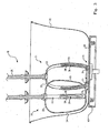
Figure 1 is a perspective view of a pair of beater elements in a mixing bowl as viewed from above according to a first preferred embodiment of the invention. -
Figure 2 is a perspective view of the pair of beater elements offigure 1 as viewed from below. -
Figure 3 is a sectioned side elevation view of the pair of beaters offigures 1 and2 in a mixing bowl placed on a turntable. -
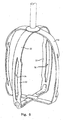
Figure 4 is a perspective view of an inner beater element according to a further preferred embodiment of the invention. -
Figure 5 is a perspective view of an inner beater element according to yet a further preferred embodiment of the invention. - In a first preferred embodiment of the present invention as shown in
figure 1 , a pair ofbeater elements 10 positioned in amixing bowl 30 are conventionally driven in counter rotating motion by an electric motor and suitable gearing (not shown).Mixing bowl 30 is positioned on aturntable 40 as may be seen infigure 3 which is also driven to rotate by conventional means (not shown). - The pair of
beaters 10 is comprised ofouter beater 20 andinner beater 21. Each ofouter beater 20 andinner beater 21 comprises at least four radially disposedmixing blades 22 formed as loops of relatively thin strip material as shown infigures 1 and2 . The blades are so arranged and controlled by the beater rotation mechanism thatrespective blades 22 of the pair ofbeaters 10 mesh while rotating but without making contact with one another. -
Outer beater 20 is positioned so as to leave a minimal gap between its rotational envelope and theinside surface 31 of mixingbowl 30 as may best be seen infigure 3 . - Preferably, though not essentially, both
outer beater 20 andinner beater 21 lie on a line extending radially from the centre of mixingbowl 30, withinner beater 21 approximately positioned at the centre of the bowl. In at least one preferred form of the invention the overlapping rotational envelopes thus formed by the rotating beaters cover an area of the bottom 32 of mixingbowl 30 in the range of 20 to 30 percent. - The pair of
beater elements 10 is adapted to operate in a substantially flat-bottomedbowl 30 andouter beater 20 andinner beater 21 are in at least one preferred form of the invention of substantially similar construction and dimensions. However at least one pair of opposingblades 22A and 22B ofinner beater 21 is provided withnon-abrading inserts 23 forming downwardly projectingpaddle elements 24. Preferably inserts 23 are of a hard-wearing but non-abrasive plastic and are retained after insertion into slots provided for the purpose by, for example, heat staking. - The pair of
beater elements 10 is conventionally retained in a mixer head (not shown) which may be pivotally rotated between a first position in which the beaters are raised above the mixing bowl rim and a second, operating position, in which the outer and inner beater are generally vertically depending within the bowl. Thelower portions 24 ofinserts 23 are urged to maintain contact with the bottom 32 of mixingbowl 30 by the downward spring-loading ofbeater shaft 25 ofinner beater 21 when the beaters are in the second operating position.Outer beater 20 is so arranged as to make no contact with any part of the inside of mixingbowl 30. - The function of downwardly projecting
paddle elements 24 when the mixer is in use for mixing small quantities of ingredients, is to urge those ingredients outwardly towards theinside surface 31 of mixingbowl 30. Instead or remaining in a thin layer spread across the extent of the base of the mixing bowl with the beaters rotating ineffectually above, the ingredients tend to concentrate towards the inside surface of the side of the bowl. Thus they are continually being urged into the overlapping portions of the lower parts of the rotational envelopes of both inner and outer beaters. By this means quite small quantities of ingredients may be mixed efficiently in a relatively large size mixing bowl thereby allowing a single bowl to serve for a full range of quantities of ingredients and recipe specified mixing requirements. - The
blades 22 of both outer andinner beaters slots 26 extending at least along a widened portion of the substantially vertical portion ofblades 22. As may best be seen infigure 2 , in at least onepreferred form slots 26 are located indeformed portions 27 so that theedges 28 ofslots 26 do not lie in the same cylinder of rotation as the strip material forming the blade in the region of the slot and thus do not follow the same rotational path of the outer edges 29. - The provision of
slots 26 effectively doubles the number of edges passing through the ingredients placed in the mixing bowl. This is of particular benefit in the mixing of light material where the action of the blades so provided significantly reduces the time required to stiffen material such as egg white and cream for example. - In a further preferred embodiment of a beater element as shown in
figure 4 the stripmaterial forming blades 22 is again provided with aslot 26, but the strip on one side of the slot is deformed inwardly to form a bowedportion 33. This arrangement also provides for a doubling of the edges passing through the ingredients. - In yet a further embodiment of a beater element as shown in
figure 5 a similar doubling of edges is effected also by the provision ofslots 26 and the deformation of the strip material on one side of the slot in such a way that the greater part of the portion conforms to the shape of the strip material on the other side of the slot but is offset radially and inwardly from it. - The above describes only some embodiments of the present invention and modifications, obvious to those skilled in the art, can be made thereto without departing from the scope and spirit of the present invention.
Claims (14)
- A mixer apparatus operating in a rotating bowl (30) for the mixing of food ingredients; comprising a pair of counter rotating beater elements; an outer beater element (20) and an inner beater element (21); said outer beater element (20) and said inner beater element (21) meshing while rotating without making contact one with another; characterized in that said apparatus comprises opposing blades of at least one of said beater elements provided with non abrading inserts (23); a said insert located on each opposing blade of said at least one beater element; said inserts adapted to urging small quantities of said food ingredients from a thin distributed layer of said food ingredients spread across the base of said bowl into a mixable concentration of said ingredients.
- The mixer apparatus of claim 1 wherein said non abrading inserts (23) comprise paddle elements located at the lower end of at least one of said beater elements (20)(21).
- The mixer apparatus of claims 1 or 2 wherein each of said pair of beater elements (20) (21) comprises a support shaft (25) and a plurality of radially disposed blade elements (22).
- The mixer apparatus of claim 3 wherein each of said plurality of blade elements (22) is formed of strip material shaped to form a generally outwardly projecting loop attached to the lower end of said supporting shaft (25) at a first end and interconnected at a second end of said loop.
- The mixer apparatus of claim 3 or 4 wherein said plurality of blade elements (22) comprises four equispaced blade elements.
- The mixer apparatus of claim 5 wherein said paddle elements (23) project downwardly from at least two of said blade elements (22).
- The mixer apparatus of claim 5 or 6 wherein said paddle elements (23) are retained in slots provided in said blade elements (22).
- The mixer apparatus of any one of claims 2 to 7 wherein said paddle elements (23) are urged into contact with the base (32) of said mixing bowl (30) when said pair of beater elements (20) (21) are positioned within said mixing bowl for use.
- The mixer apparatus of claim 8 wherein said paddle elements (20) (21) are maintained in contact with said base (32) by means of downwardly urging said support shaft (25) by spring means acting on the upper end of said shaft.
- The mixer apparatus of any one of claims 1 to 9 wherein said outer beater element (20) is proximate to the inside surface (31) of the side of said mixing bowl.
- The mixer apparatus of any one of claims 1 to 10 wherein said inner beater element (21) is proximate to the centre of said mixing bowl (30); said outer beater element (20) and said inner beater element (21) arranged so as to have overlapping envelopes of rotation.
- The mixer apparatus of claim 11 wherein said mixable concentration of said ingredients is formed substantially in an area adjacent to the inside surface (31) of the side of said bowl (30) and substantially within said envelopes of rotation.
- The mixer apparatus of any one of claims 3 to 12 wherein each of said blade elements (22) is provided with a slot (26) extending for a portion of the generally vertical portions of said loop; edges of said slot (26) adapted to provide additional mixing effect for light liquid food ingredients.
- The mixer apparatus of claim 4 wherein a portion (27) of said strip material on a first side of said slot (26) is displaced inwardly relative to the second side.
Applications Claiming Priority (2)
| Application Number | Priority Date | Filing Date | Title |
|---|---|---|---|
| AU2004901553A AU2004901553A0 (en) | 2004-03-24 | Improved Mixer Apparatus | |
| PCT/AU2005/000398 WO2005089606A1 (en) | 2004-03-24 | 2005-03-22 | Improved mixer apparatus |
Publications (3)
| Publication Number | Publication Date |
|---|---|
| EP1734852A1 EP1734852A1 (en) | 2006-12-27 |
| EP1734852A4 EP1734852A4 (en) | 2008-02-27 |
| EP1734852B1 true EP1734852B1 (en) | 2010-02-10 |
Family
ID=34993392
Family Applications (1)
| Application Number | Title | Priority Date | Filing Date |
|---|---|---|---|
| EP05714270A Not-in-force EP1734852B1 (en) | 2004-03-24 | 2005-03-22 | Improved mixer apparatus |
Country Status (6)
| Country | Link |
|---|---|
| US (1) | US8267573B2 (en) |
| EP (1) | EP1734852B1 (en) |
| CN (1) | CN2838501Y (en) |
| AT (1) | ATE457150T1 (en) |
| DE (1) | DE602005019278D1 (en) |
| WO (1) | WO2005089606A1 (en) |
Families Citing this family (19)
| Publication number | Priority date | Publication date | Assignee | Title |
|---|---|---|---|---|
| DE602005019278D1 (en) * | 2004-03-24 | 2010-03-25 | Ian Geoffrey Wilson | IMPROVED MIXING DEVICE |
| CA2698635A1 (en) * | 2007-09-14 | 2009-03-19 | E.I. Du Pont De Nemours & Company | Liquid seed dressing method for dressing small quantities of seed |
| WO2009079682A1 (en) * | 2007-12-21 | 2009-07-02 | Sunbeam Corporation Limited | A beater |
| US20100309746A1 (en) * | 2009-06-05 | 2010-12-09 | Andersson Per-Olof K | Ultraclean Magnetic Mixer with Shear-Facilitating Blade Openings |
| DE102009045706A1 (en) * | 2009-10-14 | 2011-04-21 | BSH Bosch und Siemens Hausgeräte GmbH | Stirring device for an electric kitchen appliance |
| EP2338394A1 (en) | 2009-12-28 | 2011-06-29 | Koninklijke Philips Electronics N.V. | Beater assembly and kitchen appliance with a beater assembly |
| DE102010016596B4 (en) * | 2010-04-22 | 2015-10-22 | Zeppelin Reimelt Gmbh | mixer |
| GB2480302A (en) | 2010-05-13 | 2011-11-16 | Kenwood Ltd | Beater assembly |
| JP2014012261A (en) * | 2012-07-05 | 2014-01-23 | Inoue Mfg Inc | Planetary mixer |
| JP6137664B2 (en) * | 2012-11-16 | 2017-05-31 | 株式会社貝印刃物開発センター | Attachment of hand mixer |
| US9605911B1 (en) * | 2012-12-17 | 2017-03-28 | Jack G. Kramer, Jr. | Beverage cooling system |
| GB2519368A (en) * | 2013-10-21 | 2015-04-22 | Kenwood Ltd | Kitchen machine with splash guard |
| CN103931688A (en) * | 2014-03-25 | 2014-07-23 | 鼎海精机大丰有限公司 | Cake material-mixing apparatus |
| US9526256B1 (en) | 2015-06-05 | 2016-12-27 | Francis Walters | Mixing paddle |
| WO2017151381A1 (en) * | 2016-03-01 | 2017-09-08 | Spectrum Brands, Inc. | Helical beater member and beater system |
| JP6160976B1 (en) * | 2017-01-11 | 2017-07-12 | 三広アステック株式会社 | Parallel stirring blade |
| EP3608015B1 (en) | 2018-08-08 | 2021-10-06 | Harro Höfliger Verpackungsmaschinen GmbH | Powder provision device for a powder metering apparatus |
| USD939273S1 (en) | 2020-08-18 | 2021-12-28 | Whirlpool Corporation | Beater attachment for a handheld mixer |
| USD990236S1 (en) * | 2021-06-21 | 2023-06-27 | Whirlpool Corporation | Beater attachment |
Family Cites Families (72)
| Publication number | Priority date | Publication date | Assignee | Title |
|---|---|---|---|---|
| US88320A (en) * | 1869-03-30 | Improvement in churns | ||
| US20804A (en) * | 1858-07-06 | Chtten | ||
| US60330A (en) * | 1866-12-11 | Improved mash-machine | ||
| US229372A (en) * | 1880-06-29 | Egg-beater | ||
| US410356A (en) * | 1889-09-03 | Churn | ||
| US512354A (en) * | 1894-01-09 | Apparatus for mixing flour of different grades | ||
| US140891A (en) * | 1873-07-15 | Improvement in egg and cake beaters | ||
| US122505A (en) * | 1872-01-02 | Improvement in rotary churn-dashers | ||
| US826839A (en) * | 1904-11-05 | 1906-07-24 | William B Jones | Butter-separator. |
| US849273A (en) * | 1906-07-10 | 1907-04-02 | Ernst Jacobus Schuirmann | Beater or mixer. |
| US902577A (en) * | 1906-10-29 | 1908-11-03 | Harry F Hall | Culinary utensil. |
| US877066A (en) * | 1907-05-16 | 1908-01-21 | Alpheus Fay | Cream and butter separator. |
| US969018A (en) * | 1909-07-17 | 1910-08-30 | Joseph Willmann | Apparatus for manufacturing artificially-soured milk. |
| US1430704A (en) * | 1920-02-05 | 1922-10-03 | Howard L Wadsworth | Sand-mixing apparatus |
| US1390343A (en) * | 1920-10-30 | 1921-09-13 | Reuben B Disbrow | Combined churn and butter-worker |
| US1483551A (en) * | 1923-05-14 | 1924-02-12 | Clifford C Mosher | Adjustable blade for mixing machines |
| US1723620A (en) * | 1926-05-05 | 1929-08-06 | Charles W Hottmann | Mixer |
| US1739149A (en) * | 1929-01-04 | 1929-12-10 | Heim Daniel Claude | Mixing mill |
| US1853997A (en) * | 1931-01-12 | 1932-04-12 | Robinson Henry | Washing machine for spinach, etc. |
| US1898945A (en) * | 1931-06-12 | 1933-02-21 | Fitzgerald Mfg Co | Electric utility device and motor assembly |
| US1859226A (en) * | 1931-06-15 | 1932-05-17 | Peter S Vosbikian | Wood scraper |
| US1984557A (en) * | 1932-04-02 | 1934-12-18 | Duroi Products Corp | Mixer and beater |
| US2042791A (en) * | 1934-04-03 | 1936-06-02 | P A Geier Co | Beater |
| US2027756A (en) * | 1934-12-20 | 1936-01-14 | Lee Metal Products Company Inc | Center line scraper agitator |
| US2093534A (en) * | 1936-04-16 | 1937-09-21 | Chicago Flexible Shaft Co | Household mixer |
| US2181078A (en) * | 1937-05-26 | 1939-11-21 | American Mach & Foundry | Mixing machine beater |
| US2178269A (en) * | 1939-01-23 | 1939-10-31 | Seybert Theodore | Batter mixer scraping mechanism |
| US2318534A (en) * | 1941-08-30 | 1943-05-04 | Seybert Theodore | Batter mixer |
| US2552972A (en) * | 1948-05-19 | 1951-05-15 | Sunbeam Corp | Means for rotating mixer bowls |
| US2599070A (en) * | 1950-04-11 | 1952-06-03 | Dormeyer Corp | Food mixer |
| US2615690A (en) * | 1951-01-19 | 1952-10-28 | Sunbeam Corp | Beater and bowl arrangement for mixers |
| GB722310A (en) * | 1952-02-19 | 1955-01-19 | Winsted Hardware Mfg Company | Improvements in or relating to blade assemblies for food and beverage mixers |
| US2726851A (en) * | 1953-01-21 | 1955-12-13 | Gerber Prod | Agitating heater |
| US2699925A (en) * | 1953-07-09 | 1955-01-18 | Oster John Mfg Co | Household mixer having axially retractable beaters |
| US2864595A (en) * | 1953-12-24 | 1958-12-16 | Silex Co | Apparatus for freezing desserts |
| US2747845A (en) * | 1954-09-16 | 1956-05-29 | Oster John Mfg Co | Household mixer with axially yieldable beaters |
| US2817503A (en) * | 1954-11-12 | 1957-12-24 | Oster John Mfg Co | Food mixer with axially retractable beaters |
| US3005399A (en) * | 1959-01-15 | 1961-10-24 | Maurice E Libson | Food mixing apparatus |
| US3118165A (en) * | 1962-02-15 | 1964-01-21 | Joseph Sassano | Squeegee suction cleaner |
| DE1206129B (en) * | 1963-04-27 | 1965-12-02 | Electrostar G M B H | Passing device or mushroom for drive connection with an electric motor-driven, hand-portable kitchen machine |
| US3415497A (en) * | 1967-04-24 | 1968-12-10 | Scovill Manufacturing Co | Combined blender and spatula |
| US3544081A (en) * | 1968-03-15 | 1970-12-01 | Hans A Eckhardt | Apparatus for mixing flowable materials |
| US3583176A (en) * | 1969-08-11 | 1971-06-08 | Cecil E Gordy | Power-operated means for producing frozen deserts in a refrigerated compartment |
| JPS4823255B1 (en) * | 1970-04-27 | 1973-07-12 | ||
| US3656718A (en) * | 1970-07-30 | 1972-04-18 | Dynamics Corp America | Helical blade mixer |
| US3914956A (en) * | 1974-01-28 | 1975-10-28 | Raytheon Co | Soft ice cream dispenser |
| US4095307A (en) * | 1976-06-28 | 1978-06-20 | Lox Equipment Company | Scraper for a vessel interior surface |
| US4312596A (en) * | 1978-05-24 | 1982-01-26 | Tokyo Electric Limited | Beating blade member of beater |
| US4197018A (en) * | 1979-01-08 | 1980-04-08 | Groen Division - Dover Corporation | Mixer |
| GB2081115A (en) * | 1980-06-24 | 1982-02-17 | Thorn Domestic Appliances Ltd | A whisk for a domestic food mixer or processor |
| SE425210B (en) * | 1981-01-30 | 1982-09-13 | Persson Goeran Maskin Ab | PROCEDURE AND DEVICE FOR MIXING FLUID AND PASTAL-LIKE MASSES |
| US4571090A (en) * | 1984-04-11 | 1986-02-18 | General Signal Corp. | Mixing systems |
| DE3543745A1 (en) * | 1985-12-11 | 1987-06-19 | Bhs Bayerische Berg | DOUBLE SHAFT MIXER FOR CONTINUOUS AND DISCONTINUOUS OPERATION |
| US4790667A (en) * | 1986-09-15 | 1988-12-13 | J. C. Pardo And Sons | Food process agitator |
| US4946285A (en) * | 1990-03-08 | 1990-08-07 | Hobart Corporation | Bowl scraper attachment for planetary food mixer |
| US5074125A (en) * | 1990-09-14 | 1991-12-24 | Schifferly Richard E | Rotary mixer with resinous scraper blades |
| US5249861A (en) * | 1991-07-18 | 1993-10-05 | Kusel Equipment Co. | Apparatus for cooling, washing, draining, and blending liquid suspended materials |
| DE4239252A1 (en) * | 1992-11-21 | 1994-02-10 | Braun Ag | Prodn. of ice-cream in the home - using container which resists heat and cold, and beater motor with independent power source |
| US5354129A (en) * | 1993-08-12 | 1994-10-11 | Yowell Donald H | Mixing-cutting paddle |
| US5615951A (en) * | 1995-12-11 | 1997-04-01 | J. C. Pardo & Sons | Food process agitators |
| JP3239258B2 (en) * | 1996-07-04 | 2001-12-17 | 京セラミタ株式会社 | Stirrer and toner cartridge having the same |
| FR2768607B1 (en) * | 1997-09-25 | 1999-12-03 | Seb Sa | PREPARATION ACCESSORY FOR CULINARY EMULSIONS, FOAMS AND DISPERSIONS, AND HOUSEHOLD APPLIANCES OR HOUSEHOLD APPLIANCES |
| JP3776249B2 (en) * | 1998-04-07 | 2006-05-17 | 梶原工業株式会社 | mixer |
| WO2001030221A1 (en) * | 1999-10-22 | 2001-05-03 | Koninklijke Philips Electronics N.V. | Domestic appliance having spring-loaded tools |
| EP1211972B1 (en) * | 2000-06-27 | 2004-01-21 | Koninklijke Philips Electronics N.V. | Hand-held mixer having a switching means configuration for switching to several lower speeds and for switching to a higher speed of mixing tools |
| ES2373845T3 (en) * | 2002-03-14 | 2012-02-09 | Stryker Corporation | MIXER TO MIX BONE CEMENT. |
| US6866413B2 (en) * | 2002-12-23 | 2005-03-15 | Premark Feg L.L.C. | Bowl scraper and related attachment system for mixing machine |
| US6932503B2 (en) * | 2003-05-30 | 2005-08-23 | Gary Fallowes | Food scraper attachment for food mixer |
| DE602005019278D1 (en) * | 2004-03-24 | 2010-03-25 | Ian Geoffrey Wilson | IMPROVED MIXING DEVICE |
| CA2592117C (en) * | 2005-01-31 | 2010-12-21 | Louis Busick | Mixer blade attachment with flexible fins |
| US7314308B2 (en) * | 2005-03-21 | 2008-01-01 | Gary Fallowes | Mixing bowl with attachment |
| US20060268659A1 (en) * | 2005-05-27 | 2006-11-30 | Randy Kaas | Beater apparatus and method |
-
2005
- 2005-03-22 DE DE602005019278T patent/DE602005019278D1/en active Active
- 2005-03-22 AT AT05714270T patent/ATE457150T1/en not_active IP Right Cessation
- 2005-03-22 WO PCT/AU2005/000398 patent/WO2005089606A1/en active Application Filing
- 2005-03-22 EP EP05714270A patent/EP1734852B1/en not_active Not-in-force
- 2005-03-24 CN CNU2005200073579U patent/CN2838501Y/en not_active Expired - Lifetime
-
2006
- 2006-09-22 US US11/527,661 patent/US8267573B2/en not_active Expired - Fee Related
Also Published As
| Publication number | Publication date |
|---|---|
| EP1734852A1 (en) | 2006-12-27 |
| ATE457150T1 (en) | 2010-02-15 |
| US8267573B2 (en) | 2012-09-18 |
| CN2838501Y (en) | 2006-11-22 |
| EP1734852A4 (en) | 2008-02-27 |
| WO2005089606A1 (en) | 2005-09-29 |
| US20070064523A1 (en) | 2007-03-22 |
| DE602005019278D1 (en) | 2010-03-25 |
Similar Documents
| Publication | Publication Date | Title |
|---|---|---|
| EP1734852B1 (en) | Improved mixer apparatus | |
| US6488403B2 (en) | Food mixer with whisk attachment | |
| US4765746A (en) | Dough kneader | |
| JP3632827B2 (en) | Stirrer | |
| US4911557A (en) | Dual-spindle blender with provision for small charge | |
| US8337072B2 (en) | Stirring tool having blades supported at radially inward edge | |
| CN210330373U (en) | Stirring accessory and household cooking appliance comprising same | |
| EP2338394A1 (en) | Beater assembly and kitchen appliance with a beater assembly | |
| AU2008340181B2 (en) | A beater | |
| AU2005223873B2 (en) | Improved mixer apparatus | |
| US4648720A (en) | Beating/emulsifying tool for a domestic electrical appliance for food preparation | |
| JP2523001B2 (en) | Cooking device | |
| JPH10179427A (en) | Motor-driven cooker | |
| EP0113506A1 (en) | A sifting device | |
| JPH02195921A (en) | Cooker | |
| US4669672A (en) | Food processor | |
| EP0042681A2 (en) | A beater tool for a domestic food mixing device | |
| JPH01145031A (en) | Cooker | |
| JP3649892B2 (en) | Cooking device | |
| JPS6114341Y2 (en) | ||
| JPH036804B2 (en) | ||
| JPS584578Y2 (en) | mixer | |
| AU8966298A (en) | Food mixer with impeller with reversible rotation | |
| WO1988006000A1 (en) | Mixing and kneading of farinaceous material | |
| JPH0751113B2 (en) | kitchenware |
Legal Events
| Date | Code | Title | Description |
|---|---|---|---|
| PUAI | Public reference made under article 153(3) epc to a published international application that has entered the european phase |
Free format text: ORIGINAL CODE: 0009012 |
|
| 17P | Request for examination filed |
Effective date: 20061024 |
|
| AK | Designated contracting states |
Kind code of ref document: A1 Designated state(s): AT BE BG CH CY CZ DE DK EE ES FI FR GB GR HU IE IS IT LI LT LU MC NL PL PT RO SE SI SK TR |
|
| DAX | Request for extension of the european patent (deleted) | ||
| A4 | Supplementary search report drawn up and despatched |
Effective date: 20080129 |
|
| 17Q | First examination report despatched |
Effective date: 20080818 |
|
| GRAP | Despatch of communication of intention to grant a patent |
Free format text: ORIGINAL CODE: EPIDOSNIGR1 |
|
| GRAS | Grant fee paid |
Free format text: ORIGINAL CODE: EPIDOSNIGR3 |
|
| GRAA | (expected) grant |
Free format text: ORIGINAL CODE: 0009210 |
|
| AK | Designated contracting states |
Kind code of ref document: B1 Designated state(s): AT BE BG CH CY CZ DE DK EE ES FI FR GB GR HU IE IS IT LI LT LU MC NL PL PT RO SE SI SK TR |
|
| REG | Reference to a national code |
Ref country code: GB Ref legal event code: FG4D |
|
| REG | Reference to a national code |
Ref country code: CH Ref legal event code: EP |
|
| REG | Reference to a national code |
Ref country code: IE Ref legal event code: FG4D |
|
| REF | Corresponds to: |
Ref document number: 602005019278 Country of ref document: DE Date of ref document: 20100325 Kind code of ref document: P |
|
| REG | Reference to a national code |
Ref country code: CH Ref legal event code: NV Representative=s name: MURGITROYD & COMPANY |
|
| REG | Reference to a national code |
Ref country code: NL Ref legal event code: VDEP Effective date: 20100210 |
|
| LTIE | Lt: invalidation of european patent or patent extension |
Effective date: 20100210 |
|
| PG25 | Lapsed in a contracting state [announced via postgrant information from national office to epo] |
Ref country code: PT Free format text: LAPSE BECAUSE OF FAILURE TO SUBMIT A TRANSLATION OF THE DESCRIPTION OR TO PAY THE FEE WITHIN THE PRESCRIBED TIME-LIMIT Effective date: 20100611 Ref country code: LT Free format text: LAPSE BECAUSE OF FAILURE TO SUBMIT A TRANSLATION OF THE DESCRIPTION OR TO PAY THE FEE WITHIN THE PRESCRIBED TIME-LIMIT Effective date: 20100210 Ref country code: IS Free format text: LAPSE BECAUSE OF FAILURE TO SUBMIT A TRANSLATION OF THE DESCRIPTION OR TO PAY THE FEE WITHIN THE PRESCRIBED TIME-LIMIT Effective date: 20100610 Ref country code: ES Free format text: LAPSE BECAUSE OF FAILURE TO SUBMIT A TRANSLATION OF THE DESCRIPTION OR TO PAY THE FEE WITHIN THE PRESCRIBED TIME-LIMIT Effective date: 20100521 |
|
| PG25 | Lapsed in a contracting state [announced via postgrant information from national office to epo] |
Ref country code: SI Free format text: LAPSE BECAUSE OF FAILURE TO SUBMIT A TRANSLATION OF THE DESCRIPTION OR TO PAY THE FEE WITHIN THE PRESCRIBED TIME-LIMIT Effective date: 20100210 Ref country code: AT Free format text: LAPSE BECAUSE OF FAILURE TO SUBMIT A TRANSLATION OF THE DESCRIPTION OR TO PAY THE FEE WITHIN THE PRESCRIBED TIME-LIMIT Effective date: 20100210 Ref country code: FI Free format text: LAPSE BECAUSE OF FAILURE TO SUBMIT A TRANSLATION OF THE DESCRIPTION OR TO PAY THE FEE WITHIN THE PRESCRIBED TIME-LIMIT Effective date: 20100210 Ref country code: PL Free format text: LAPSE BECAUSE OF FAILURE TO SUBMIT A TRANSLATION OF THE DESCRIPTION OR TO PAY THE FEE WITHIN THE PRESCRIBED TIME-LIMIT Effective date: 20100210 |
|
| PG25 | Lapsed in a contracting state [announced via postgrant information from national office to epo] |
Ref country code: SE Free format text: LAPSE BECAUSE OF FAILURE TO SUBMIT A TRANSLATION OF THE DESCRIPTION OR TO PAY THE FEE WITHIN THE PRESCRIBED TIME-LIMIT Effective date: 20100210 Ref country code: NL Free format text: LAPSE BECAUSE OF FAILURE TO SUBMIT A TRANSLATION OF THE DESCRIPTION OR TO PAY THE FEE WITHIN THE PRESCRIBED TIME-LIMIT Effective date: 20100210 Ref country code: MC Free format text: LAPSE BECAUSE OF NON-PAYMENT OF DUE FEES Effective date: 20100331 Ref country code: GR Free format text: LAPSE BECAUSE OF FAILURE TO SUBMIT A TRANSLATION OF THE DESCRIPTION OR TO PAY THE FEE WITHIN THE PRESCRIBED TIME-LIMIT Effective date: 20100511 Ref country code: EE Free format text: LAPSE BECAUSE OF FAILURE TO SUBMIT A TRANSLATION OF THE DESCRIPTION OR TO PAY THE FEE WITHIN THE PRESCRIBED TIME-LIMIT Effective date: 20100210 Ref country code: CY Free format text: LAPSE BECAUSE OF FAILURE TO SUBMIT A TRANSLATION OF THE DESCRIPTION OR TO PAY THE FEE WITHIN THE PRESCRIBED TIME-LIMIT Effective date: 20100210 Ref country code: BE Free format text: LAPSE BECAUSE OF FAILURE TO SUBMIT A TRANSLATION OF THE DESCRIPTION OR TO PAY THE FEE WITHIN THE PRESCRIBED TIME-LIMIT Effective date: 20100210 Ref country code: RO Free format text: LAPSE BECAUSE OF FAILURE TO SUBMIT A TRANSLATION OF THE DESCRIPTION OR TO PAY THE FEE WITHIN THE PRESCRIBED TIME-LIMIT Effective date: 20100210 |
|
| PG25 | Lapsed in a contracting state [announced via postgrant information from national office to epo] |
Ref country code: SK Free format text: LAPSE BECAUSE OF FAILURE TO SUBMIT A TRANSLATION OF THE DESCRIPTION OR TO PAY THE FEE WITHIN THE PRESCRIBED TIME-LIMIT Effective date: 20100210 Ref country code: CZ Free format text: LAPSE BECAUSE OF FAILURE TO SUBMIT A TRANSLATION OF THE DESCRIPTION OR TO PAY THE FEE WITHIN THE PRESCRIBED TIME-LIMIT Effective date: 20100210 Ref country code: BG Free format text: LAPSE BECAUSE OF FAILURE TO SUBMIT A TRANSLATION OF THE DESCRIPTION OR TO PAY THE FEE WITHIN THE PRESCRIBED TIME-LIMIT Effective date: 20100510 |
|
| PLBE | No opposition filed within time limit |
Free format text: ORIGINAL CODE: 0009261 |
|
| STAA | Information on the status of an ep patent application or granted ep patent |
Free format text: STATUS: NO OPPOSITION FILED WITHIN TIME LIMIT |
|
| 26N | No opposition filed |
Effective date: 20101111 |
|
| PG25 | Lapsed in a contracting state [announced via postgrant information from national office to epo] |
Ref country code: IE Free format text: LAPSE BECAUSE OF NON-PAYMENT OF DUE FEES Effective date: 20100322 Ref country code: DK Free format text: LAPSE BECAUSE OF FAILURE TO SUBMIT A TRANSLATION OF THE DESCRIPTION OR TO PAY THE FEE WITHIN THE PRESCRIBED TIME-LIMIT Effective date: 20100210 |
|
| PG25 | Lapsed in a contracting state [announced via postgrant information from national office to epo] |
Ref country code: IT Free format text: LAPSE BECAUSE OF FAILURE TO SUBMIT A TRANSLATION OF THE DESCRIPTION OR TO PAY THE FEE WITHIN THE PRESCRIBED TIME-LIMIT Effective date: 20100210 |
|
| PG25 | Lapsed in a contracting state [announced via postgrant information from national office to epo] |
Ref country code: HU Free format text: LAPSE BECAUSE OF FAILURE TO SUBMIT A TRANSLATION OF THE DESCRIPTION OR TO PAY THE FEE WITHIN THE PRESCRIBED TIME-LIMIT Effective date: 20100811 Ref country code: LU Free format text: LAPSE BECAUSE OF NON-PAYMENT OF DUE FEES Effective date: 20100322 |
|
| PG25 | Lapsed in a contracting state [announced via postgrant information from national office to epo] |
Ref country code: TR Free format text: LAPSE BECAUSE OF FAILURE TO SUBMIT A TRANSLATION OF THE DESCRIPTION OR TO PAY THE FEE WITHIN THE PRESCRIBED TIME-LIMIT Effective date: 20100210 |
|
| REG | Reference to a national code |
Ref country code: FR Ref legal event code: PLFP Year of fee payment: 12 |
|
| PGFP | Annual fee paid to national office [announced via postgrant information from national office to epo] |
Ref country code: CH Payment date: 20160322 Year of fee payment: 12 |
|
| REG | Reference to a national code |
Ref country code: CH Ref legal event code: NV Representative=s name: E. BLUM AND CO. AG PATENT- UND MARKENANWAELTE , CH |
|
| REG | Reference to a national code |
Ref country code: DE Ref legal event code: R082 Ref document number: 602005019278 Country of ref document: DE Representative=s name: WINTER, BRANDL, FUERNISS, HUEBNER, ROESS, KAIS, DE |
|
| PGFP | Annual fee paid to national office [announced via postgrant information from national office to epo] |
Ref country code: GB Payment date: 20170317 Year of fee payment: 13 |
|
| REG | Reference to a national code |
Ref country code: FR Ref legal event code: PLFP Year of fee payment: 13 |
|
| PGFP | Annual fee paid to national office [announced via postgrant information from national office to epo] |
Ref country code: FR Payment date: 20170925 Year of fee payment: 13 |
|
| REG | Reference to a national code |
Ref country code: CH Ref legal event code: PL |
|
| PG25 | Lapsed in a contracting state [announced via postgrant information from national office to epo] |
Ref country code: LI Free format text: LAPSE BECAUSE OF NON-PAYMENT OF DUE FEES Effective date: 20170331 Ref country code: CH Free format text: LAPSE BECAUSE OF NON-PAYMENT OF DUE FEES Effective date: 20170331 |
|
| PGFP | Annual fee paid to national office [announced via postgrant information from national office to epo] |
Ref country code: DE Payment date: 20180525 Year of fee payment: 14 |
|
| GBPC | Gb: european patent ceased through non-payment of renewal fee |
Effective date: 20180322 |
|
| PG25 | Lapsed in a contracting state [announced via postgrant information from national office to epo] |
Ref country code: GB Free format text: LAPSE BECAUSE OF NON-PAYMENT OF DUE FEES Effective date: 20180322 |
|
| PG25 | Lapsed in a contracting state [announced via postgrant information from national office to epo] |
Ref country code: FR Free format text: LAPSE BECAUSE OF NON-PAYMENT OF DUE FEES Effective date: 20180331 |
|
| REG | Reference to a national code |
Ref country code: DE Ref legal event code: R119 Ref document number: 602005019278 Country of ref document: DE |
|
| PG25 | Lapsed in a contracting state [announced via postgrant information from national office to epo] |
Ref country code: DE Free format text: LAPSE BECAUSE OF NON-PAYMENT OF DUE FEES Effective date: 20191001 |