EP1734378A2 - Methods and systems using relative sensing to locate targets - Google Patents
Methods and systems using relative sensing to locate targets Download PDFInfo
- Publication number
- EP1734378A2 EP1734378A2 EP06115205A EP06115205A EP1734378A2 EP 1734378 A2 EP1734378 A2 EP 1734378A2 EP 06115205 A EP06115205 A EP 06115205A EP 06115205 A EP06115205 A EP 06115205A EP 1734378 A2 EP1734378 A2 EP 1734378A2
- Authority
- EP
- European Patent Office
- Prior art keywords
- target
- range
- sensor
- measured
- reference target
- Prior art date
- Legal status (The legal status is an assumption and is not a legal conclusion. Google has not performed a legal analysis and makes no representation as to the accuracy of the status listed.)
- Withdrawn
Links
Images


Classifications
-
- G—PHYSICS
- G01—MEASURING; TESTING
- G01S—RADIO DIRECTION-FINDING; RADIO NAVIGATION; DETERMINING DISTANCE OR VELOCITY BY USE OF RADIO WAVES; LOCATING OR PRESENCE-DETECTING BY USE OF THE REFLECTION OR RERADIATION OF RADIO WAVES; ANALOGOUS ARRANGEMENTS USING OTHER WAVES
- G01S5/00—Position-fixing by co-ordinating two or more direction or position line determinations; Position-fixing by co-ordinating two or more distance determinations
- G01S5/02—Position-fixing by co-ordinating two or more direction or position line determinations; Position-fixing by co-ordinating two or more distance determinations using radio waves
- G01S5/0284—Relative positioning
-
- F—MECHANICAL ENGINEERING; LIGHTING; HEATING; WEAPONS; BLASTING
- F41—WEAPONS
- F41G—WEAPON SIGHTS; AIMING
- F41G3/00—Aiming or laying means
- F41G3/02—Aiming or laying means using an independent line of sight
-
- F—MECHANICAL ENGINEERING; LIGHTING; HEATING; WEAPONS; BLASTING
- F41—WEAPONS
- F41G—WEAPON SIGHTS; AIMING
- F41G3/00—Aiming or laying means
- F41G3/06—Aiming or laying means with rangefinder
-
- G—PHYSICS
- G01—MEASURING; TESTING
- G01C—MEASURING DISTANCES, LEVELS OR BEARINGS; SURVEYING; NAVIGATION; GYROSCOPIC INSTRUMENTS; PHOTOGRAMMETRY OR VIDEOGRAMMETRY
- G01C15/00—Surveying instruments or accessories not provided for in groups G01C1/00 - G01C13/00
- G01C15/002—Active optical surveying means
-
- G—PHYSICS
- G01—MEASURING; TESTING
- G01S—RADIO DIRECTION-FINDING; RADIO NAVIGATION; DETERMINING DISTANCE OR VELOCITY BY USE OF RADIO WAVES; LOCATING OR PRESENCE-DETECTING BY USE OF THE REFLECTION OR RERADIATION OF RADIO WAVES; ANALOGOUS ARRANGEMENTS USING OTHER WAVES
- G01S19/00—Satellite radio beacon positioning systems; Determining position, velocity or attitude using signals transmitted by such systems
- G01S19/38—Determining a navigation solution using signals transmitted by a satellite radio beacon positioning system
- G01S19/39—Determining a navigation solution using signals transmitted by a satellite radio beacon positioning system the satellite radio beacon positioning system transmitting time-stamped messages, e.g. GPS [Global Positioning System], GLONASS [Global Orbiting Navigation Satellite System] or GALILEO
- G01S19/42—Determining position
- G01S19/51—Relative positioning
-
- G—PHYSICS
- G01—MEASURING; TESTING
- G01S—RADIO DIRECTION-FINDING; RADIO NAVIGATION; DETERMINING DISTANCE OR VELOCITY BY USE OF RADIO WAVES; LOCATING OR PRESENCE-DETECTING BY USE OF THE REFLECTION OR RERADIATION OF RADIO WAVES; ANALOGOUS ARRANGEMENTS USING OTHER WAVES
- G01S5/00—Position-fixing by co-ordinating two or more direction or position line determinations; Position-fixing by co-ordinating two or more distance determinations
- G01S5/02—Position-fixing by co-ordinating two or more direction or position line determinations; Position-fixing by co-ordinating two or more distance determinations using radio waves
- G01S5/0205—Details
- G01S5/021—Calibration, monitoring or correction
Definitions
- This invention relates generally to target locators, and more specifically, to methods and systems for incorporating relative sensing in the location of targets.
- a target locator is used to remotely locate a target by measuring a range and a direction (e.g., azimuth and elevation angles) to the target.
- the location of the target for example, in coordinates, is then computed based on the GPS coordinates of the position of the target locator and the range and direction.
- the target location is then utilized by a command and control center to guide surveillance or a weapon system to the computed location of the target.
- the target location process utilizes gyro-compassing techniques coupled with a laser range finder to obtain an absolute direction and range to the target.
- this target locator system is only suitable for large explosive weapon systems because there are some inaccuracies in the range and direction measurements. These inaccuracies result in a circular error probability (CEP) of approximately 80 meters-
- CEP circular error probability
- the existing target locator system does not provide the necessary target location accuracies.
- a CEP about five meters at ranges of about five kilometers is desired.
- a method for determining a position of a target comprises establishing a reference target position and a measuring location position and measuring a range to the target, an azimuth angle to the target, and an elevation angle to the target. The method further comprises utilizing the reference target position, the measuring location position, the measured range to the target, the azimuth angle to the target, and the elevation angle to the target to calculate a position of the target.
- a target location system comprises at least one source of reference target position information and system position information, a rangefinder configured to measure a range to a reference target position and a range to the target, and a magnetic field source at a position of the target location system.
- the target location system further comprises a sensor configured to utilize the magnetic field source to determine azimuth angles to a reference target position and the target, an inclinometer to measure elevation angles to a reference target position and the target, and a processor.
- the processor is programmed to determine a position of the target using reference target position information, system position information, the measured ranges, the measured azimuth angles, and the measured elevation angle.
- a target location processor is provided that is programmed to calculate a range to a reference position based on a received reference position and a received measuring location position, receive a measured range to the reference position and a measured range to the target position with respect to the measuring location position, calculate a bias error using the measured range to the reference position and the measured range to the reference position, and offset a received range measurement to a target location according to the bias error.
- the systems and methods provide accuracy for a target locator that is improved by as much as ten times over known target location mechanisms.
- the systems and methods provide circular error probability (CEP) accuracies of approaching five meters at ranges of five kilometers which results in a capability of using low cost, small explosive weapon systems to engage such targets.
- CEP circular error probability
- the target locator utilizes relative sensing to accurately determine the position of the target.
- a method performed by the target locating system includes establishing a reference target position, for example, using a GPS determination and assuming that any GPS errors are the same at both the reference location and the measuring location position, which allows cancellation of the GPS errors.
- a range measurement between the present location and the reference target is computed and compared to the range as measured by a range finder to establish a rangefinder bias error to be used as an offset when determining the range to the target location.
- the system in one embodiment, incorporates an anisotropic magneto-resistive (AMR) sensor to measure an angular position of the target.
- AMR anisotropic magneto-resistive
- Known target locator systems are used to determine absolute range, azimuth, and elevation measurements from a remote position to a designated target.
- a laser rangefinder is used to measure range to the target
- a magneto-resistive compass sensor that senses earth's magnetic field is used for azimuth location
- an inclinometer is used to determine elevation.
- FIG. 1 is a block diagram of the known target locator system 10.
- GPS 12 provides a target locator position x p , y p , and z p .
- the sights specifically, a day operation sight 14 or a night operation (i.e. thermal) sight, each contain a reticle that is used to accurately align laser rangefinder 18, magnetic compass 20, and inclinometer 22 to the target.
- the above described components of system 10 are controlled by and provide data to system processor/interface 24 which provides data to display 26 where it can be viewed by an operator of system 10.
- System 10 includes a rotary platform 30 on which the above described components are mounted, and rotary platform 30 is attached to a stationary, adjustable tripod 32. All components of system 10 that utilize power are supplied that power from battery/power supply 34.
- Range to the target is determined using laser rangefinder 18.
- An azimuth angle to the target is measured from magnetic north by magnetic compass 20, and elevation angle to the target is measured using inclinometer 22- Because the azimuth sensor (e.g., magnetic compass 20) measures angles referenced to magnetic north (i.e. earth magnetic field strength ⁇ 1 gauss), it is prone to variability and inaccuracies.
- the earth's magnetic field is relatively weak and also varies as a function of earth position. Other magnetic disturbances in close proximity also can affect operation of magnetic compass 20.
- FIG. 10 illustrates the target positioning mechanization incorporated within system 10 where a range to the target 50 is determined utilizing magnetic north as determined by magnetic compass 20.
- the mechanization of system 10 is changed to determine a relative direction to a target (e.g., relative to the direction to a fixed reference target) and further to utilize knowledge of the reference target position and the direction to it to compute an actual position of the target.
- a more accurate relative direction e.g., in azimuth and elevation
- the sensor mechanization results in improved azimuth and elevation accuracies for the target.
- Figure 3 is a diagram of a system 100 configured to utilize relative sensing to determine target positions.
- Components of system 100 which are the same as components of system 10 (shown in Figure 1) are denoted utilizing the same reference numerals.
- system 100 incorporates a anisotropic magneto-resistive (AMR) sensor 102 rather than magnetic compass 20 (shown in Figure 1) and the system/processor interface 104 is necessarily updated to support the incorporation of AMR sensor 102.
- a magnet 106 is mounted on tripod 32 for operation of sensor 102.
- a range to the target, Rt is determined, as well as the azimuth angle to the target, ⁇ t, and elevation angle to the target, ⁇ t.
- Relative sensing uses a surveyed reference target position that minimizes or eliminates common mode or bias errors found in present target positioning solutions.
- IMU Inertial Measurement Unit
- Relative sensing of target positions includes relative GPS measurements, relative azimuth measurements, and relative elevation measurements.
- Reference target position 120 e.g., x rt , y rt , z rt
- Reference target position 120 is measured either while on the way to a measuring location position 120 (x p , y p , z p ) or by a person traveling to a reference target and taking a reference GPS reading.
- Other methods of providing reference target position, including GPS determination, are contemplated.
- Figure 4 is an operational diagram illustrative of relative sensing. If the GPS "surveyed" positions are highly accurate, then the reference target location 120 can be selected to be closer to the measuring position 122 (x p , y p , z p ). Therefore, the range, Rrt, to the reference target 120 can be relative small (i.e. 200 to 500 meters). If the GPS "surveyed" positions have moderate errors (i.e. 1 to 2 meters), then the location of the reference target should be approximately the same distance as the actual target 124 to minimize errors resulting from "survey" errors.
- the relative GPS errors are small, and that either the same GPS receiver (e.g., GPS 12) or another GPS receiver with similar error characteristics is used, and the measurement time between the two points 122 and 120 (x p , y p , z p and x rt , y rt , z rt ) is small (i.e., the GPS satellite positions are similar), the error at both these locations is then related and as a result, most of the GPS errors will be cancelled resulting in the relative position of the reference target 120 to the measurement location 122 being very accurate.
- range, Rrt By assuming positions x p , y p , z p and x rt , y rt , z rt are accurately "surveyed” using GPS, then exact range, Rrt, between these two points can be computed to establish range truth.
- range, Rrt can be measured and compared against the range truth- A laser rangefinder bias error is then determined and used as a bias error offset when the actual target range, Rt, is measured.
- the range to the target 124 can be measured very accurately, for example, to within one-half meter.
- system 100 incorporates a non-contact, high resolution anisotropic magneto-resistive (AMR) sensor 102 that is utilized to measure an angular position.
- AMR sensors are very accurate, reliable, and provide long life.
- sensor 102 is capable of measuring the angle direction of a magnetic field from a self-contained magnet with less than 0.05 degree resolution.
- a magnet 106 for sensor 102 is located on stationary tripod section 32 and AMR sensor is aligned and then rotated with the optical sights 14 and 16 and laser rangefinder 18.
- the field strength from magnet 106 at sensor 102 is 100 times the strength of the earth's magnetic field and as a result, is more stable and less susceptible to perturbations from outside environments-
- the field direction is not critical since relative angular positions are measured rather than absolute angular positions. As a result, there is minimal calibration of the AMR sensor mechanization in the field.
- output is from a Wheatstone bridge (not shown) that permits balanced output signals for noise immunity.
- a low offset amplifier and high resolution delta-sigma converter i.e. an analog to digital converter
- ⁇ 0.05 degree is utilized to meet the accuracy of ⁇ 0.05 degree.
- an operational scenario for using system 100 is that the sight reticle (14, 16) is moved to align with reference target 120. The angle between the magnetic field and the reference target 120 is then measured ( ⁇ mrt). The sight reticle is then moved to the target and the angle between the magnetic field and the target is measured ( ⁇ mt). Subtracting one angle from the other results in the angle between the reference target and the actual target ( ⁇ mt - ⁇ mrt). The angle ⁇ rt is calculated knowing the reference target position, As a result, the target azimuth angle ( ⁇ t) can be determined. Because of the high accuracy and resolution of the angular position sensor, ⁇ t can measured to an accuracy of ⁇ 0.05 degrees or 0.87 milliradians.
- AMR sensors 102 provide relative target direction (relative to a fixed reference target).
- the AMR sensor's capability to measure relative target direction can be enhanced with a low cost Micro-Electro Mechanical Systems Inertial Measurement Unit 110 (MEMS IMU) to accurately calibrate AMR sensors 102 in the field prior to its use in system 100 if necessary.
- MEMS IMU 110 can also be used to determine the integrity of the directional information from AMR sesnor 102 with a high level of confidence.
Landscapes
- Engineering & Computer Science (AREA)
- Radar, Positioning & Navigation (AREA)
- Remote Sensing (AREA)
- Physics & Mathematics (AREA)
- General Physics & Mathematics (AREA)
- General Engineering & Computer Science (AREA)
- Computer Networks & Wireless Communication (AREA)
- Position Fixing By Use Of Radio Waves (AREA)
- Radar Systems Or Details Thereof (AREA)
- Navigation (AREA)
Abstract
Description
- This application claims priority to
U.S. Provisional Application Serial Number 60/689,424, filed June 10,2005 - This invention relates generally to target locators, and more specifically, to methods and systems for incorporating relative sensing in the location of targets.
- A target locator is used to remotely locate a target by measuring a range and a direction (e.g., azimuth and elevation angles) to the target. The location of the target, for example, in coordinates, is then computed based on the GPS coordinates of the position of the target locator and the range and direction. The target location is then utilized by a command and control center to guide surveillance or a weapon system to the computed location of the target.
- In one known system, the target location process utilizes gyro-compassing techniques coupled with a laser range finder to obtain an absolute direction and range to the target. However, this target locator system is only suitable for large explosive weapon systems because there are some inaccuracies in the range and direction measurements. These inaccuracies result in a circular error probability (CEP) of approximately 80 meters- For lower cost and smaller explosive weapon systems, the existing target locator system does not provide the necessary target location accuracies. For these smaller explosive weapons systems, a CEP of about five meters at ranges of about five kilometers is desired.
- The existing system using absolute target measurement techniques along with the gyro-compassing mechanization is not capable of meeting these higher accuracy requirements. Therefore, a different target locator mechanization is needed to meet the higher accuracies desired.
- In one aspect, a method for determining a position of a target is provided. The method comprises establishing a reference target position and a measuring location position and measuring a range to the target, an azimuth angle to the target, and an elevation angle to the target. The method further comprises utilizing the reference target position, the measuring location position, the measured range to the target, the azimuth angle to the target, and the elevation angle to the target to calculate a position of the target.
- In another aspect, a target location system is provided that comprises at least one source of reference target position information and system position information, a rangefinder configured to measure a range to a reference target position and a range to the target, and a magnetic field source at a position of the target location system. The target location system further comprises a sensor configured to utilize the magnetic field source to determine azimuth angles to a reference target position and the target, an inclinometer to measure elevation angles to a reference target position and the target, and a processor. The processor is programmed to determine a position of the target using reference target position information, system position information, the measured ranges, the measured azimuth angles, and the measured elevation angle.
- In still another aspect, a target location processor is provided that is programmed to calculate a range to a reference position based on a received reference position and a received measuring location position, receive a measured range to the reference position and a measured range to the target position with respect to the measuring location position, calculate a bias error using the measured range to the reference position and the measured range to the reference position, and offset a received range measurement to a target location according to the bias error.
- Figure 1 is a block diagram of a target locating system.
- Figure 2 illustrates determination of the target location by the system of Figure 1 using a magnetic compass.
- Figure 3 is a block diagram of a system configured to utilize relative sensing to determine target location that incorporates an anisotropic magneto-resistive sensor.
- Figure 4 illustrates determination of target location utilizing a reference target location and the system of Figure 3.
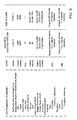
- Figure 5 is a chart describing a performance summary of the systems of Figures 1 and 3.
- Described are systems and methods that use relative sensing with respect to a fixed reference target along with an accurate azimuth and elevation sensor mechanization. The systems and methods provide accuracy for a target locator that is improved by as much as ten times over known target location mechanisms. The systems and methods provide circular error probability (CEP) accuracies of approaching five meters at ranges of five kilometers which results in a capability of using low cost, small explosive weapon systems to engage such targets.
- The target locator utilizes relative sensing to accurately determine the position of the target. A method performed by the target locating system includes establishing a reference target position, for example, using a GPS determination and assuming that any GPS errors are the same at both the reference location and the measuring location position, which allows cancellation of the GPS errors. A range measurement between the present location and the reference target is computed and compared to the range as measured by a range finder to establish a rangefinder bias error to be used as an offset when determining the range to the target location. The system, in one embodiment, incorporates an anisotropic magneto-resistive (AMR) sensor to measure an angular position of the target.
- Known target locator systems are used to determine absolute range, azimuth, and elevation measurements from a remote position to a designated target. In at least one of these target locator systems, a laser rangefinder is used to measure range to the target, a magneto-resistive compass sensor that senses earth's magnetic field is used for azimuth location, and an inclinometer is used to determine elevation.
- Figure 1 is a block diagram of the known
target locator system 10.GPS 12 provides a target locator position xp, yp, and zp. The sights, specifically, aday operation sight 14 or a night operation (i.e. thermal) sight, each contain a reticle that is used to accurately alignlaser rangefinder 18,magnetic compass 20, andinclinometer 22 to the target. The above described components ofsystem 10 are controlled by and provide data to system processor/interface 24 which provides data to display 26 where it can be viewed by an operator ofsystem 10.System 10 includes arotary platform 30 on which the above described components are mounted, androtary platform 30 is attached to a stationary,adjustable tripod 32. All components ofsystem 10 that utilize power are supplied that power from battery/power supply 34. - Range to the target is determined using
laser rangefinder 18. An azimuth angle to the target is measured from magnetic north bymagnetic compass 20, and elevation angle to the target is measured using inclinometer 22- Because the azimuth sensor (e.g., magnetic compass 20) measures angles referenced to magnetic north (i.e. earth magnetic field strength < 1 gauss), it is prone to variability and inaccuracies. The earth's magnetic field is relatively weak and also varies as a function of earth position. Other magnetic disturbances in close proximity also can affect operation ofmagnetic compass 20. - Further complicating utilization of
system 10 is thatmagnetic compass 20 requires a precision calibration in the field aftersystem 10 is set up. Even with this calibration process, an accuracy of about only about ten millirads can be achieved. With a target at a range of 5000 meters, an azimuth uncertainty of ten millirads results in a position uncertainty of about fifty meters-Inclinometer 22 also is not capable of meeting high accuracy requirements as its accuracy is, for example, only about seven and a half millirads. Figure 2 illustrates the target positioning mechanization incorporated withinsystem 10 where a range to thetarget 50 is determined utilizing magnetic north as determined bymagnetic compass 20. - To provide more accurate targeting, the mechanization of
system 10 is changed to determine a relative direction to a target (e.g., relative to the direction to a fixed reference target) and further to utilize knowledge of the reference target position and the direction to it to compute an actual position of the target. The utilization of a more accurate relative direction (e.g., in azimuth and elevation) for the sensor mechanization results in improved azimuth and elevation accuracies for the target. - Figure 3 is a diagram of a
system 100 configured to utilize relative sensing to determine target positions. Components ofsystem 100 which are the same as components of system 10 (shown in Figure 1) are denoted utilizing the same reference numerals. As further described below,system 100 incorporates a anisotropic magneto-resistive (AMR)sensor 102 rather than magnetic compass 20 (shown in Figure 1) and the system/processor interface 104 is necessarily updated to support the incorporation ofAMR sensor 102. Amagnet 106 is mounted ontripod 32 for operation ofsensor 102. - To find the position of the target, a range to the target, Rt, is determined, as well as the azimuth angle to the target, θt, and elevation angle to the target, φt. Relative sensing uses a surveyed reference target position that minimizes or eliminates common mode or bias errors found in present target positioning solutions. By using a low cost Inertial Measurement Unit (IMU) for accurate elevation measurements, it can also measure accurately, for a short period of time, azimuth angles. As a result, the IMU can be used to test or calibrate the AMR azimuth sensing. Relative sensing of target positions includes relative GPS measurements, relative azimuth measurements, and relative elevation measurements.
- More specifically, and referring now to Figure 4, relative sensing is accomplished by establishing a reference target position that is located in less-hostile areas. Reference target position 120 (e.g., xrt, yrt, zrt) is measured either while on the way to a measuring location position 120 (xp, yp, zp) or by a person traveling to a reference target and taking a reference GPS reading. Other methods of providing reference target position, including GPS determination, are contemplated.
- Figure 4 is an operational diagram illustrative of relative sensing. If the GPS "surveyed" positions are highly accurate, then the
reference target location 120 can be selected to be closer to the measuring position 122 (xp, yp, zp). Therefore, the range, Rrt, to thereference target 120 can be relative small (i.e. 200 to 500 meters). If the GPS "surveyed" positions have moderate errors (i.e. 1 to 2 meters), then the location of the reference target should be approximately the same distance as theactual target 124 to minimize errors resulting from "survey" errors. - By assuming that the relative GPS errors are small, and that either the same GPS receiver (e.g., GPS 12) or another GPS receiver with similar error characteristics is used, and the measurement time between the two
points 122 and 120 (xp, yp, zp and xrt, yrt, zrt) is small (i.e., the GPS satellite positions are similar), the error at both these locations is then related and as a result, most of the GPS errors will be cancelled resulting in the relative position of thereference target 120 to themeasurement location 122 being very accurate. - By assuming positions xp, yp, zp and xrt, yrt, zrt are accurately "surveyed" using GPS, then exact range, Rrt, between these two points can be computed to establish range truth. Using laser rangefinder 18 (shown in Figure 3), range, Rrt, can be measured and compared against the range truth- A laser rangefinder bias error is then determined and used as a bias error offset when the actual target range, Rt, is measured. As a result, the range to the
target 124 can be measured very accurately, for example, to within one-half meter. - Instead of using a magnetic compass sensor (e,g., magnetic compass 20 (shown in Figure 1) as does
system 10,system 100 incorporates a non-contact, high resolution anisotropic magneto-resistive (AMR)sensor 102 that is utilized to measure an angular position. AMR sensors are very accurate, reliable, and provide long life. As such,sensor 102 is capable of measuring the angle direction of a magnetic field from a self-contained magnet with less than 0.05 degree resolution. - The advantages of measuring field direction versus field strength (i.e. like magnetic compass 20) include: an insensitivity to the temperature coefficient of the magnet, less sensitivity to shock and vibration, and the ability to withstand large variations in the gap between the sensor and magnet. In one embodiment, a
magnet 106 forsensor 102 is located onstationary tripod section 32 and AMR sensor is aligned and then rotated with theoptical sights laser rangefinder 18. - The field strength from
magnet 106 atsensor 102 is 100 times the strength of the earth's magnetic field and as a result, is more stable and less susceptible to perturbations from outside environments- The field direction is not critical since relative angular positions are measured rather than absolute angular positions. As a result, there is minimal calibration of the AMR sensor mechanization in the field. In one embodiment, output is from a Wheatstone bridge (not shown) that permits balanced output signals for noise immunity. A low offset amplifier and high resolution delta-sigma converter (i.e. an analog to digital converter) is utilized to meet the accuracy of ± 0.05 degree. - In one embodiment, an operational scenario for using
system 100 is that the sight reticle (14, 16) is moved to align withreference target 120. The angle between the magnetic field and thereference target 120 is then measured (θmrt). The sight reticle is then moved to the target and the angle between the magnetic field and the target is measured (θmt). Subtracting one angle from the other results in the angle between the reference target and the actual target (θmt - θmrt). The angle θrt is calculated knowing the reference target position, As a result, the target azimuth angle (θt) can be determined. Because of the high accuracy and resolution of the angular position sensor, θt can measured to an accuracy of ± 0.05 degrees or 0.87 milliradians. -
AMR sensors 102 provide relative target direction (relative to a fixed reference target). The AMR sensor's capability to measure relative target direction can be enhanced with a low cost Micro-Electro Mechanical Systems Inertial Measurement Unit 110 (MEMS IMU) to accurately calibrateAMR sensors 102 in the field prior to its use insystem 100 if necessary. In addition,MEMS IMU 110 can also be used to determine the integrity of the directional information from AMR sesnor 102 with a high level of confidence. - While the invention has been described in terms of various specific embodiments, those skilled in the art will recognize that the invention can be practiced with modification within the spirit and scope of the claims.
Claims (6)
- A target location system (100) comprising:at least one source (12) of reference target position (120) information and system position (122) information;a rangefinder (18) configured to measure a range to a reference target position and a range to the target (124);a magnetic field source (106) at a position of said system;a sensor (102) configured to utilize said magnetic field source to determine azimuth angles to a reference target position and the target;an inclinometer (22) to measure elevation angles to a reference target position and the target; anda processor (104) programmed to determine a position of the target using reference target position information, system position information, the measured ranges, the measured azimuth angles, and the measured elevation angle.
- A target location system (100) according to Claim 1 further comprising a thermal sight having a reticle, said thermal sight configurable to align said range finder (18), said sensor (102), and said inclinometer (22).
- A target location system (100) according to Claim 1 further comprising a day sight having a reticle, said day sight configurable to align said range finder (18), said sensor (102), and said inclinometer (22).
- A target location system (100) according to Claim 1 wherein to determine a position of a target (50), said processor (104) is configured to:calculate a range to the reference target position (120) based on the reference target position and the measuring location position (122);receive a measured range to the reference target position and the target position with respect to the measuring location position from said range finder (18);calculate a range finder bias error using the measured range and calculated range; andoffset the range measurement to the target location according to the range finder bias error.
- A target location system (100) according to Claim 1 wherein sensor (102) comprises an anistropic magneto-resistive sensor.
- A target location system (100) according to Claim 1 further comprising an inertial measurement unit (IMU) (110) coupled to said processor (104), said processor programmed to utilize data from said IMU to calibrate said anistropic magneto-resistive sensor (102).
Applications Claiming Priority (2)
| Application Number | Priority Date | Filing Date | Title |
|---|---|---|---|
| US68942405P | 2005-06-10 | 2005-06-10 | |
| US11/343,718 US7453395B2 (en) | 2005-06-10 | 2006-01-31 | Methods and systems using relative sensing to locate targets |
Publications (2)
| Publication Number | Publication Date |
|---|---|
| EP1734378A2 true EP1734378A2 (en) | 2006-12-20 |
| EP1734378A3 EP1734378A3 (en) | 2007-01-03 |
Family
ID=36809142
Family Applications (1)
| Application Number | Title | Priority Date | Filing Date |
|---|---|---|---|
| EP06115205A Withdrawn EP1734378A3 (en) | 2005-06-10 | 2006-06-09 | Methods and systems using relative sensing to locate targets |
Country Status (3)
| Country | Link |
|---|---|
| US (1) | US7453395B2 (en) |
| EP (1) | EP1734378A3 (en) |
| IL (1) | IL176240A0 (en) |
Cited By (3)
| Publication number | Priority date | Publication date | Assignee | Title |
|---|---|---|---|---|
| ITMI20081879A1 (en) * | 2008-10-23 | 2010-04-24 | Giuseppe Tempestini & C S R L | METHOD AND DEVICE FOR THE DETECTION OF THE GEOGRAPHIC POSITION OF A UNBIECTIVE |
| GB2511339A (en) * | 2013-02-28 | 2014-09-03 | Rockwell Collins Uk Ltd | Apparatus for locating a remote point of interest |
| EP4177567A1 (en) * | 2021-11-05 | 2023-05-10 | Getac Technology Corporation | Method for measuring coordinate position and portable electronic device using the same |
Families Citing this family (11)
| Publication number | Priority date | Publication date | Assignee | Title |
|---|---|---|---|---|
| US7239377B2 (en) | 2004-10-13 | 2007-07-03 | Bushnell Performance Optics | Method, device, and computer program for determining a range to a target |
| SE529504C2 (en) * | 2005-05-25 | 2007-08-28 | Bae Systems Bofors Ab | Systems, procedure, device, use of device and computer program product for target presentation |
| US20090002677A1 (en) * | 2007-06-26 | 2009-01-01 | Honeywell International Inc. | Target locator system |
| WO2009064982A1 (en) | 2007-11-14 | 2009-05-22 | Raytheon Company | System and method for precision collaborative targeting |
| US20100023185A1 (en) * | 2008-07-28 | 2010-01-28 | Torc Technologies, Llc | Devices and methods for waypoint target generation and mission spooling for mobile ground robots |
| US9182470B2 (en) * | 2009-11-17 | 2015-11-10 | Cogentrix Development Holdings, Llc | Inclinometer for a solar array and associated systems, methods, and computer program products |
| US8620023B1 (en) * | 2010-09-13 | 2013-12-31 | The Boeing Company | Object detection and location system |
| US8787114B1 (en) | 2010-09-13 | 2014-07-22 | The Boeing Company | Audio surveillance system |
| EP3929525A1 (en) * | 2013-10-31 | 2021-12-29 | AeroVironment, Inc. | Interactive weapon targeting system displaying remote sensed image of target area |
| US9494686B2 (en) * | 2014-06-10 | 2016-11-15 | Cubic Corporation | Hand-held target locator |
| US9440351B2 (en) | 2014-10-30 | 2016-09-13 | International Business Machines Corporation | Controlling the operations of a robotic device |
Family Cites Families (31)
| Publication number | Priority date | Publication date | Assignee | Title |
|---|---|---|---|---|
| US3836259A (en) * | 1971-04-08 | 1974-09-17 | Department Of Civil Aviat | Apparatus for tracking a luminous object |
| US4179088A (en) * | 1976-11-17 | 1979-12-18 | The United States Of America As Represented By The Secretary Of The Army | Offset beacon homing |
| US4281809A (en) * | 1979-12-13 | 1981-08-04 | The United States Of America As Represented By The Secretary Of The Navy | Method of precision bombing |
| US4988189A (en) * | 1981-10-08 | 1991-01-29 | Westinghouse Electric Corp. | Passive ranging system especially for use with an electro-optical imaging system |
| US4488876A (en) * | 1982-03-26 | 1984-12-18 | The United States Of America As Represented By The Secretary Of The Navy | Aimpoint processor for quantizing target data |
| US6487953B1 (en) * | 1985-04-15 | 2002-12-03 | The United States Of America As Represented By The Secretary Of The Army | Fire control system for a short range, fiber-optic guided missile |
| US5341143A (en) * | 1987-07-24 | 1994-08-23 | Northrop Grumman Corporation | Hierarchical tracker and method |
| US5020902A (en) * | 1989-06-22 | 1991-06-04 | Kvh Industries, Inc. | Rangefinder with heads-up display |
| US4954833A (en) * | 1989-07-05 | 1990-09-04 | The United States Of America As Represented By The Secretary Of The Navy | Method for determining astronomic azimuth |
| US4949089A (en) * | 1989-08-24 | 1990-08-14 | General Dynamics Corporation | Portable target locator system |
| US5344105A (en) * | 1992-09-21 | 1994-09-06 | Hughes Aircraft Company | Relative guidance using the global positioning system |
| US5408541A (en) * | 1993-01-05 | 1995-04-18 | Lockheed Corporation | Method and system for recognizing targets at long ranges |
| US5528518A (en) * | 1994-10-25 | 1996-06-18 | Laser Technology, Inc. | System and method for collecting data used to form a geographic information system database |
| GB2300082B (en) | 1995-04-21 | 1999-09-22 | British Aerospace | Altitude measuring methods |
| DE69730278T2 (en) | 1996-07-17 | 2005-08-11 | Raytheon Company, Waltham | Passive distance estimation using image size dimensions |
| US6064942A (en) * | 1997-05-30 | 2000-05-16 | Rockwell Collins, Inc. | Enhanced precision forward observation system and method |
| US7856750B2 (en) * | 1997-12-08 | 2010-12-28 | Horus Vision Llc | Apparatus and method for calculating aiming point information |
| DE19813631A1 (en) * | 1998-03-27 | 1999-10-07 | Honeywell Ag | Radar range finder |
| US5912642A (en) * | 1998-04-28 | 1999-06-15 | Ball Aerospace & Technologies Corp. | Method and system for aligning a sensor on a platform |
| EP1067361A1 (en) | 1999-07-06 | 2001-01-10 | Datalogic S.P.A. | Method and a device for measuring the distance of an object |
| US6489922B1 (en) * | 2000-04-22 | 2002-12-03 | American Gnc Corporation | Passive/ranging/tracking processing method for collision avoidance guidance and control |
| GB0014719D0 (en) * | 2000-06-16 | 2000-08-09 | Koninkl Philips Electronics Nv | A method of providing an estimate of a location |
| US6930715B1 (en) * | 2000-07-21 | 2005-08-16 | The Research Foundation Of The State University Of New York | Method, system and program product for augmenting an image of a scene with information about the scene |
| US6466158B2 (en) * | 2000-12-08 | 2002-10-15 | Lockheed Martin Corp. | Identifying closely clustered moving targets |
| US7031875B2 (en) * | 2001-01-24 | 2006-04-18 | Geo Vector Corporation | Pointing systems for addressing objects |
| US6658354B2 (en) * | 2002-03-15 | 2003-12-02 | American Gnc Corporation | Interruption free navigator |
| GB2394376A (en) | 2002-10-14 | 2004-04-21 | Bertho Boman | Measuring distance between two objects |
| US20060023204A1 (en) * | 2004-07-28 | 2006-02-02 | Zoltan Filep | Laser-GPS marking and targeting system |
| US7266477B2 (en) * | 2005-06-22 | 2007-09-04 | Deere & Company | Method and system for sensor signal fusion |
| JP4977339B2 (en) | 2005-07-11 | 2012-07-18 | 株式会社トプコン | Geographic data collection device |
| US20070103671A1 (en) * | 2005-11-08 | 2007-05-10 | Honeywell International Inc. | Passive-optical locator |
-
2006
- 2006-01-31 US US11/343,718 patent/US7453395B2/en not_active Expired - Fee Related
- 2006-06-09 EP EP06115205A patent/EP1734378A3/en not_active Withdrawn
- 2006-06-11 IL IL176240A patent/IL176240A0/en unknown
Cited By (4)
| Publication number | Priority date | Publication date | Assignee | Title |
|---|---|---|---|---|
| ITMI20081879A1 (en) * | 2008-10-23 | 2010-04-24 | Giuseppe Tempestini & C S R L | METHOD AND DEVICE FOR THE DETECTION OF THE GEOGRAPHIC POSITION OF A UNBIECTIVE |
| GB2511339A (en) * | 2013-02-28 | 2014-09-03 | Rockwell Collins Uk Ltd | Apparatus for locating a remote point of interest |
| EP4177567A1 (en) * | 2021-11-05 | 2023-05-10 | Getac Technology Corporation | Method for measuring coordinate position and portable electronic device using the same |
| US11953614B2 (en) | 2021-11-05 | 2024-04-09 | Getac Technology Corporation | Method for measuring coordinate position and portable electronic device using the same |
Also Published As
| Publication number | Publication date |
|---|---|
| IL176240A0 (en) | 2006-10-05 |
| US7453395B2 (en) | 2008-11-18 |
| US20070057840A1 (en) | 2007-03-15 |
| EP1734378A3 (en) | 2007-01-03 |
Similar Documents
| Publication | Publication Date | Title |
|---|---|---|
| US8705022B2 (en) | Navigation system using both GPS and laser reference | |
| US8826550B2 (en) | Geographically north-referenced azimuth determination | |
| EP0534892B1 (en) | Position-locating method | |
| US5862511A (en) | Vehicle navigation system and method | |
| EP1774257B1 (en) | Combination laser system and global navigation satellite system | |
| US8275544B1 (en) | Magnetically stabilized forward observation platform | |
| EP0870174B1 (en) | Improved vehicle navigation system and method using gps velocities | |
| US7453395B2 (en) | Methods and systems using relative sensing to locate targets | |
| US8311757B2 (en) | Miniaturized smart self-calibration electronic pointing method and system | |
| CN104541129B (en) | Inclination sensor | |
| IL132191A (en) | Method for calibrating and verifying the attitude of a compass | |
| US7728264B2 (en) | Precision targeting | |
| RU2522784C1 (en) | Laser pointer/range-finder | |
| US6266628B1 (en) | Surveying system with an inertial measuring device | |
| US20080129599A1 (en) | Systems and methods for locating targets using digital elevation model survey points | |
| US20140249750A1 (en) | Navigational and location determination system | |
| EP2040029A1 (en) | A multi mode active surveying pole | |
| EP1726915A1 (en) | Active surveying pole | |
| KR20000033073A (en) | Automobile navigation device using by mobile communication device and gps receiver | |
| KR20140002334A (en) | Apparatus, system and method for estimating 3-dimension location of target in gps signal poor region | |
| RU116224U1 (en) | DEVICE FOR MEASURING AND REGISTRATION OF SPHERICAL COORDINATES OF A REMOTE OBJECT IN AREA | |
| Zhou et al. | Rapid repetition survey of engineering control network based on the concept of Internet of Things | |
| RU2486467C1 (en) | Apparatus for measuring and recording spherical coordinates of remote object and method of determining spherical coordinates of remote object on location | |
| RU2381447C1 (en) | Spherical positioner for remote object and method for afield positioning of remote object | |
| Brown et al. | Precision Targeting Using GPS/Inertial-Aided Sensors |
Legal Events
| Date | Code | Title | Description |
|---|---|---|---|
| PUAI | Public reference made under article 153(3) epc to a published international application that has entered the european phase |
Free format text: ORIGINAL CODE: 0009012 |
|
| PUAL | Search report despatched |
Free format text: ORIGINAL CODE: 0009013 |
|
| AK | Designated contracting states |
Kind code of ref document: A2 Designated state(s): AT BE BG CH CY CZ DE DK EE ES FI FR GB GR HU IE IS IT LI LT LU LV MC NL PL PT RO SE SI SK TR |
|
| AX | Request for extension of the european patent |
Extension state: AL BA HR MK YU |
|
| AK | Designated contracting states |
Kind code of ref document: A3 Designated state(s): AT BE BG CH CY CZ DE DK EE ES FI FR GB GR HU IE IS IT LI LT LU LV MC NL PL PT RO SE SI SK TR |
|
| AX | Request for extension of the european patent |
Extension state: AL BA HR MK YU |
|
| 17P | Request for examination filed |
Effective date: 20070622 |
|
| AKX | Designation fees paid |
Designated state(s): DE FR GB |
|
| 17Q | First examination report despatched |
Effective date: 20090211 |
|
| STAA | Information on the status of an ep patent application or granted ep patent |
Free format text: STATUS: THE APPLICATION IS DEEMED TO BE WITHDRAWN |
|
| 18D | Application deemed to be withdrawn |
Effective date: 20090822 |