EP0534892B1 - Position-locating method - Google Patents
Position-locating method Download PDFInfo
- Publication number
- EP0534892B1 EP0534892B1 EP92630089A EP92630089A EP0534892B1 EP 0534892 B1 EP0534892 B1 EP 0534892B1 EP 92630089 A EP92630089 A EP 92630089A EP 92630089 A EP92630089 A EP 92630089A EP 0534892 B1 EP0534892 B1 EP 0534892B1
- Authority
- EP
- European Patent Office
- Prior art keywords
- vehicle
- terrain
- elevation
- measured
- approximate location
- Prior art date
- Legal status (The legal status is an assumption and is not a legal conclusion. Google has not performed a legal analysis and makes no representation as to the accuracy of the status listed.)
- Expired - Lifetime
Links
Images

Classifications
-
- G—PHYSICS
- G01—MEASURING; TESTING
- G01C—MEASURING DISTANCES, LEVELS OR BEARINGS; SURVEYING; NAVIGATION; GYROSCOPIC INSTRUMENTS; PHOTOGRAMMETRY OR VIDEOGRAMMETRY
- G01C21/00—Navigation; Navigational instruments not provided for in groups G01C1/00 - G01C19/00
- G01C21/26—Navigation; Navigational instruments not provided for in groups G01C1/00 - G01C19/00 specially adapted for navigation in a road network
- G01C21/28—Navigation; Navigational instruments not provided for in groups G01C1/00 - G01C19/00 specially adapted for navigation in a road network with correlation of data from several navigational instruments
- G01C21/30—Map- or contour-matching
Definitions
- the present invention relates to a method for locating the position of a vehicle or other object travelling over a terrain.
- the invention is particularly useful in vehicle navigation systems based on dead reckoning and/or GPS (global positioning systems), and is described below with respect to both applications.
- the dead reckoning navigation system for navigating a ground vehicle over terrain is based on the use of sensors installed in the vehicle for measuring (1) the distance travelled by the vehicle, and (2) the heading (i.e., angular direction or azimuth) of the vehicle. From these two measurements, the instantaneous location of the vehicle with respect to the known starting point can be continuously determined.
- dead reckoning navigation method One of the drawbacks of the dead reckoning navigation method, however, is the accumulation of errors. For this reason, advanced navigation systems based on dead reckoning generally include an independent source of information to permit periodic correction of errors. For example, some dead reckoning navigation systems include additional information from a digitized map (i.e., road map) of the area over which the vehicle travels. The map is used in a map-matching technique to provide known reference data, such as intersection points, which may be compared with the calculated positions for correcting errors and thereby preventing an accumulation of errors.
- a digitized map i.e., road map
- the map is used in a map-matching technique to provide known reference data, such as intersection points, which may be compared with the calculated positions for correcting errors and thereby preventing an accumulation of errors.
- DE-A-3439000 and US-A-4939663 disclose methods of locating a vehicle travelling over a terrain, comprising the following operations: (a) measuring the approximate location of the vehicle as it travels over the terrain; (b) measuring the elevation of the vehicle as it travels over the terrain; and (c) utilizing said measured elevation of the vehicle for correcting the measured approximate location of the vehicle.
- Such systems generally also involve an accumulation of errors, and are therefore relatively inaccurate where large distances are involved.
- Navigation systems based on GPS are also known, as shown for example by US-A-4924402, but in low-cost civilian applications, as they are generally capable of determining only the approximate location of an object on the face of the globe, i.e., within about 150 meters. Where more accuracy is required, the cost of the system is substantially increased.
- An object of the present invention is to provide a relatively low cost method for precisely locating the position of a vehicle travelling over a terrain.
- a method of determining the instantaenous location of a land vehicle travelling over a terrain comprising operations (a), (b) and (c) set forth above; characterized in that: said operation (c) includes storing, as reference data, known locations on said terrain wherein a change in sign in the elevation slope occurs; determining, from the measured elevation, the locations where a change in sign occurs in the elevation slope of the terrain travelled by the land vehicle; and utilizing the occurrences of changes in sign in the elevation slope of the terrain travelled by the land vehicle for correcting the measured approximate location of the land vehicle by the respective known location stored in the reference data.
- operation (a) includes measuring the distances and headings of the vehicle as it travels over the terrain from a known location, and determining its approximate location by dead reckoning. More particularly, this is done by utilizing the measured changes in elevation of the land vehicle as it travels over the terrain for computing the horizontal component of the measured distances in order to determine the approximate location of the land vehicle on the terrain.
- operation (a) includes measuring the approximate location of the land vehicle on the terrain by means of a satellite global positioning system.
- the method of the present invention does not require accurately measuring the actual elevation, but requires only measuring the changes in elevation.
- These changes in elevation are used for determining where a change in sign occurs in the elevation slope (i.e., the peaks and valleys, which are easily detectable) in the terrain travelled by the land vehicle; and such determinations are then used for correcting the measured approximate location of the land vehicle by the respective known locations in the stored reference data.
- the changes in elevation are also used for more precisely determining the approximate locations by computing the horizontal component of the distances measured by dead reckoning.
- the novel method provides a relatively low-cost, accurate, method for determining the instantaneous location of a land vehicle travelling over a terrain.
- the system illustrated in Fig. 1 is intended for the navigation of a vehicle, generally designated 2, travelling over a terrain which may or may not be covered by roads.
- the vehicle 2 includes a distance sensor 4 for continuously sensing the distance travelled by the vehicle over the terrain from a known point, and a direction (heading or azimuth) sensor 6 for continuously measuring the heading of the vehicle when travelling from the known point.
- the outputs of the two sensors 4, 6 are fed, via analog-to-digital converters 4a, 6a, to a digital processor 8 which continuously computes, from the information supplied by sensors 4 and 6, the instantaneous location of the vehicle with respect to the known point by the well-known dead reckoning technique.
- the vehicle 2 also includes an elevation sensor 10 which continuously measures the elevation, or merely changes in elevation, of the vehicle 2 while travelling over the terrain.
- the output of the elevation sensor 10 is fed, via an analog-to-digital converter 10a, to the digital processor 8.
- This elevation information is also used by the processor 8, in a manner to be described more particularly below, for computing the instantaenous location of the vehicle with respect to the known point.
- Digital processor 8 further includes an input 12 of reference data which is used for calibrating or correcting the computed instantaneous location of the vehicle.
- the reference data 12 may be in the form of a three-dimensional map in digitized format of the area over which the vehicle travels and including the normal two-dimensional data (e.g., roads, intersections, sites, etc.), and also the elevational data.
- the reference map 12, which may be stored in the navigation system, identifies reference points along the vehicle travelling path, such as sharp curvatures in the road, turns at intersections, etc., whose locations are known.
- the tracked or computed data obtained from the sensors 4 and 6, is matched with the reference data obtained from the map 12, and any deviations in the computed locations from the reference locations constitute errors.
- the processor 8 is programmed to check the known reference locations with the computed locations, identify the errors, and correct the errors, so as to prevent the accumulation of such errors according to well-known map matching technique.
- the error in measuring the distance travelled by the vehicle over the terrain from the known point is reduced.
- such distances are usually measured by devices which measure the number of rotations of the vehicle wheels and then multiply the number of rotations by the known diameter of the wheels.
- a distance measurement measures the linear distance travelled by the vehicle; therefore, if the vehicle is on an ascent or descent, the actually measured distance will include an error depending on the slope. That is, the correct dead reckoning distance desired is the horizontal component of the measured distance, so that the greater the slope, the greater the error in the computed instantaneous location of the vehicle.
- the system illustrated in Fig. 1 also measures the elevation, or merely the changes in elevation, the latter measurements may be used in the digital processor 8 for deriving, from the distance measurements by sensor 4, only the horizontal component of the distance actually travelled by the vehicle, thereby producing a more accurate determination of the instantaneous location of the vehicle.
- the reference points could also be identified by elevational data, particularly the changes in sign in the elevation slope at the peaks and valleys in road ascents and descents.
- the reference map 12 By providing the reference map 12 with the locations of the peaks and valleys of ascents and descents wherein a change in sign of the slope occurs, and comparing these points with the elevation changes of the travelling vehicle 2 as measured by its elevation sensor 10, the computation of the instantaenous location of the vehicle- can be more frequently checked and corrected, thereby reducing the accumulation of errors.
- the digital computer 8 includes a control panel 14 for manually inputting data, including elevation-related data, in addition to the 3-D map stored in unit 12, and a display 16 for outputting the instantaneous location of the vehicle.
- the elevation sensor 10 may be a barometer carried by the vehicle for measuring absolute values of the vehicle elevation over sea level. Such absolute values may be used for computing changes in elevation, which in turn may be used for computing the horizontal component of the travelled distance, and also for determining the peaks and valleys (changes in sign) of the elevation slopes, and matched with the known locations of such peaks and valleys on the three-dimensional map 12. Changes in sign (peaks and valleys) are easily detectable.
- the distance sensor 4 may be a conventional odometer which measures the number of rotations of the vehicle wheels, and multiplies this measurement by the known diameter of the vehicle wheels, to determine the linear distance travelled by the vehicle. Any other distance-measuring means may be used, for example other means for measuring the vehicle speed and then accumulating the speed measurement over a period of time, to provide a distance measurement.
- the direction- (heading or azimuth) sensor 6 may comprise a magnetic-flux compass carried by the vehicle, or a plurality of gyroscopes carried by the vehicle. Such a sensor may also be one which measures the changes in steering direction of the vehicle, or which measures the differences in rotation with respect to the left and right wheels of the vehicle.
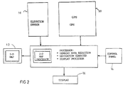
- Fig. 2 illustrates a system for locating the position of a vehicle travelling over a terrain when the approximate location of the vehicle has been obtained by a GPS (global positioning system).
- GPS global positioning system
- the vehicle in the system diagrammatically illustrated in Fig. 2, need not include a distance sensor or a direction sensor as indicated by elements 4 and 6 in Fig. 1, but may include only an elevation sensor 10 for measuring the elevation of the vehicle as it travels over the terrain.
- the illustrated system further includes a GPS, indicated by Block 20, for obtaining the approximate location of the vehicle, instead of computing this approximate location by dead reckoning as described above with respect to Fig. 1. By tracking four satelites, the elevation (altitude) can also be measured by the GPS.
- Fig. 2 The remainder of the system illustrated in Fig. 2 is substantially the same, and operates in substantially the same manner, as described above with respect to Fig. 1, except the processor 8 does not compute the approximate location by dead reckoning, but rather introduces the approximate location as obtained from the GPS 20.
- the reference map identified by Block 12 in Fig. 2, contains the 3-D map as in Fig. 1.
- the elevations of the measured data (either by sensor 10 or the GPS) used for determining the approximate location may be compared with the elevations of the reference data identifying known locations for correcting the approximate locations of the vehicle.
- the changes in sign in the elevation slope are used in this comparison of the measured data with the reference data as described above with respect to Fig. 1.
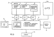
- Fig. 3 illustrates a combination system including the determination of the approximate location of the object both by dead reckoning and by GPS data. It may be desirable to provide such a combination system for use both in the city and in open fields.
- the tall buildings may interfere with the line of sight to the satellites in the GPS for determining the approximate location of the vehicle; and therefore the distance sensor 4 and the direction sensor 6 may be used for determining the vehicle's approximate location by dead reckoning.
- the GPS 20 may be used for determining the approximate location of the vehicle.
- the dead reckoning part of the system including the distance sensor 4 and the direction sensor 6, may be incorporated in the vehicle itself, and the GPS 20, as well as the elevation sensor 10 and the other elements of the system illustrated in Fig. 3, may be constructed as a separate plug-in portable unit which the user can remove from the vehicle and use for locating his position by the GPS data while moving around away from the vehicle.
Description
- The present invention relates to a method for locating the position of a vehicle or other object travelling over a terrain. The invention is particularly useful in vehicle navigation systems based on dead reckoning and/or GPS (global positioning systems), and is described below with respect to both applications.
- The dead reckoning navigation system for navigating a ground vehicle over terrain is based on the use of sensors installed in the vehicle for measuring (1) the distance travelled by the vehicle, and (2) the heading (i.e., angular direction or azimuth) of the vehicle. From these two measurements, the instantaneous location of the vehicle with respect to the known starting point can be continuously determined.
- One of the drawbacks of the dead reckoning navigation method, however, is the accumulation of errors. For this reason, advanced navigation systems based on dead reckoning generally include an independent source of information to permit periodic correction of errors. For example, some dead reckoning navigation systems include additional information from a digitized map (i.e., road map) of the area over which the vehicle travels. The map is used in a map-matching technique to provide known reference data, such as intersection points, which may be compared with the calculated positions for correcting errors and thereby preventing an accumulation of errors. However, even when such correction or recalibration data is provided by a separate source of information, the accuracy of the dead reckoning system still depends on the distance travelled from the last reference calibration point, and the larger the distance travelled before being recalibrated, the greater the possible error. Moreover, such map-matching techniques are used only with respect to known roads, and not to terrains where no road exists.
- DE-A-3439000 and US-A-4939663 disclose methods of locating a vehicle travelling over a terrain, comprising the following operations: (a) measuring the approximate location of the vehicle as it travels over the terrain; (b) measuring the elevation of the vehicle as it travels over the terrain; and (c) utilizing said measured elevation of the vehicle for correcting the measured approximate location of the vehicle. Such systems, however, generally also involve an accumulation of errors, and are therefore relatively inaccurate where large distances are involved.
- Navigation systems based on GPS are also known, as shown for example by US-A-4924402, but in low-cost civilian applications, as they are generally capable of determining only the approximate location of an object on the face of the globe, i.e., within about 150 meters. Where more accuracy is required, the cost of the system is substantially increased.
- An object of the present invention is to provide a relatively low cost method for precisely locating the position of a vehicle travelling over a terrain.
- According to the present invention, there is provided a method of determining the instantaenous location of a land vehicle travelling over a terrain, comprising operations (a), (b) and (c) set forth above; characterized in that: said operation (c) includes storing, as reference data, known locations on said terrain wherein a change in sign in the elevation slope occurs; determining, from the measured elevation, the locations where a change in sign occurs in the elevation slope of the terrain travelled by the land vehicle; and utilizing the occurrences of changes in sign in the elevation slope of the terrain travelled by the land vehicle for correcting the measured approximate location of the land vehicle by the respective known location stored in the reference data.
- According to one described preferred embodiment, operation (a) includes measuring the distances and headings of the vehicle as it travels over the terrain from a known location, and determining its approximate location by dead reckoning. More particularly, this is done by utilizing the measured changes in elevation of the land vehicle as it travels over the terrain for computing the horizontal component of the measured distances in order to determine the approximate location of the land vehicle on the terrain.
- According to a second described embodiment, operation (a) includes measuring the approximate location of the land vehicle on the terrain by means of a satellite global positioning system.
- It will thus be seen that the method of the present invention does not require accurately measuring the actual elevation, but requires only measuring the changes in elevation. These changes in elevation are used for determining where a change in sign occurs in the elevation slope (i.e., the peaks and valleys, which are easily detectable) in the terrain travelled by the land vehicle; and such determinations are then used for correcting the measured approximate location of the land vehicle by the respective known locations in the stored reference data. Where the approximate locations are measured by dead reckoning, the changes in elevation are also used for more precisely determining the approximate locations by computing the horizontal component of the distances measured by dead reckoning.
- It will thus be seen that the novel method provides a relatively low-cost, accurate, method for determining the instantaneous location of a land vehicle travelling over a terrain.
- Fig. 1 is a block diagram illustrating a dead reckoning navigation system constructed in accordance with the present invention;
- Fig. 2 is a block diagram illustrating a GPS navigation system constructed in accordance with the present invention; and
- Fig. 3 is a block diagram illustrating a combined navigation system constructed in accordance with the present invention.
- The system illustrated in Fig. 1 is intended for the navigation of a vehicle, generally designated 2, travelling over a terrain which may or may not be covered by roads. Thus, the
vehicle 2 includes adistance sensor 4 for continuously sensing the distance travelled by the vehicle over the terrain from a known point, and a direction (heading or azimuth)sensor 6 for continuously measuring the heading of the vehicle when travelling from the known point. The outputs of the twosensors digital converters digital processor 8 which continuously computes, from the information supplied bysensors - In the system illustrated in Fig. 1, however, the
vehicle 2 also includes anelevation sensor 10 which continuously measures the elevation, or merely changes in elevation, of thevehicle 2 while travelling over the terrain. The output of theelevation sensor 10 is fed, via an analog-to-digital converter 10a, to thedigital processor 8. This elevation information is also used by theprocessor 8, in a manner to be described more particularly below, for computing the instantaenous location of the vehicle with respect to the known point. -
Digital processor 8 further includes aninput 12 of reference data which is used for calibrating or correcting the computed instantaneous location of the vehicle. Thus, thereference data 12 may be in the form of a three-dimensional map in digitized format of the area over which the vehicle travels and including the normal two-dimensional data (e.g., roads, intersections, sites, etc.), and also the elevational data. Thereference map 12, which may be stored in the navigation system, identifies reference points along the vehicle travelling path, such as sharp curvatures in the road, turns at intersections, etc., whose locations are known. The tracked or computed data obtained from thesensors map 12, and any deviations in the computed locations from the reference locations constitute errors. Theprocessor 8 is programmed to check the known reference locations with the computed locations, identify the errors, and correct the errors, so as to prevent the accumulation of such errors according to well-known map matching technique. - The
reference map 12 in the system illustrated in Fig. 1, however, includes a further parameter, namely the elevations of the mapped area, and particularly of known reference points along the path of travel. These elevation reference points are also used, in accordance with the present invention, for preventing the accumulation of errors during the dead reckoning navigation of the vehicle. - By including the elevation parameter, particularly changes in elevation, provided by
elevation sensor 10, the error in measuring the distance travelled by the vehicle over the terrain from the known point is reduced. Thus, as briefly indicated earlier, such distances are usually measured by devices which measure the number of rotations of the vehicle wheels and then multiply the number of rotations by the known diameter of the wheels. However, such a distance measurement measures the linear distance travelled by the vehicle; therefore, if the vehicle is on an ascent or descent, the actually measured distance will include an error depending on the slope. That is, the correct dead reckoning distance desired is the horizontal component of the measured distance, so that the greater the slope, the greater the error in the computed instantaneous location of the vehicle. - However, since the system illustrated in Fig. 1 also measures the elevation, or merely the changes in elevation, the latter measurements may be used in the
digital processor 8 for deriving, from the distance measurements bysensor 4, only the horizontal component of the distance actually travelled by the vehicle, thereby producing a more accurate determination of the instantaneous location of the vehicle. - In addition, by using the elevational data from the
reference map 12, a new dimension of reference data is provided in the "map matching" technique for preventing an accumulation of errors. Thus, the reference points could also be identified by elevational data, particularly the changes in sign in the elevation slope at the peaks and valleys in road ascents and descents. By providing thereference map 12 with the locations of the peaks and valleys of ascents and descents wherein a change in sign of the slope occurs, and comparing these points with the elevation changes of thetravelling vehicle 2 as measured by itselevation sensor 10, the computation of the instantaenous location of the vehicle- can be more frequently checked and corrected, thereby reducing the accumulation of errors. - The
digital computer 8 includes acontrol panel 14 for manually inputting data, including elevation-related data, in addition to the 3-D map stored inunit 12, and adisplay 16 for outputting the instantaneous location of the vehicle. - The
elevation sensor 10 may be a barometer carried by the vehicle for measuring absolute values of the vehicle elevation over sea level. Such absolute values may be used for computing changes in elevation, which in turn may be used for computing the horizontal component of the travelled distance, and also for determining the peaks and valleys (changes in sign) of the elevation slopes, and matched with the known locations of such peaks and valleys on the three-dimensional map 12. Changes in sign (peaks and valleys) are easily detectable. - As indicated earlier, the
distance sensor 4 may be a conventional odometer which measures the number of rotations of the vehicle wheels, and multiplies this measurement by the known diameter of the vehicle wheels, to determine the linear distance travelled by the vehicle. Any other distance-measuring means may be used, for example other means for measuring the vehicle speed and then accumulating the speed measurement over a period of time, to provide a distance measurement. - The direction- (heading or azimuth)
sensor 6 may comprise a magnetic-flux compass carried by the vehicle, or a plurality of gyroscopes carried by the vehicle. Such a sensor may also be one which measures the changes in steering direction of the vehicle, or which measures the differences in rotation with respect to the left and right wheels of the vehicle. - Fig. 2 illustrates a system for locating the position of a vehicle travelling over a terrain when the approximate location of the vehicle has been obtained by a GPS (global positioning system). As indicated earlier, such global positioning systems are known, but for low-cost civilian applications, they are usually accurate only to about 150 meters. However, by measuring the elevation of the vehicle as it travels over the terrain, and including this parameter, the location of the vehicle as approximately obtained by the GPS may be more precisely determined.
- Thus, in the system diagrammatically illustrated in Fig. 2, the vehicle, generally designated 2, need not include a distance sensor or a direction sensor as indicated by
elements elevation sensor 10 for measuring the elevation of the vehicle as it travels over the terrain. The illustrated system further includes a GPS, indicated byBlock 20, for obtaining the approximate location of the vehicle, instead of computing this approximate location by dead reckoning as described above with respect to Fig. 1. By tracking four satelites, the elevation (altitude) can also be measured by the GPS. - The remainder of the system illustrated in Fig. 2 is substantially the same, and operates in substantially the same manner, as described above with respect to Fig. 1, except the
processor 8 does not compute the approximate location by dead reckoning, but rather introduces the approximate location as obtained from theGPS 20. - The reference map, identified by
Block 12 in Fig. 2, contains the 3-D map as in Fig. 1. Thus, the elevations of the measured data (either bysensor 10 or the GPS) used for determining the approximate location may be compared with the elevations of the reference data identifying known locations for correcting the approximate locations of the vehicle. For this purpose, the changes in sign in the elevation slope are used in this comparison of the measured data with the reference data as described above with respect to Fig. 1. - Fig. 3 illustrates a combination system including the determination of the approximate location of the object both by dead reckoning and by GPS data. It may be desirable to provide such a combination system for use both in the city and in open fields. Thus, when the vehicle is in the city, the tall buildings may interfere with the line of sight to the satellites in the GPS for determining the approximate location of the vehicle; and therefore the
distance sensor 4 and thedirection sensor 6 may be used for determining the vehicle's approximate location by dead reckoning. However, when the vehicle leaves the city so that there is no longer interference with the line of sight to the satellite, theGPS 20 may be used for determining the approximate location of the vehicle. - It is contemplated that the dead reckoning part of the system, including the
distance sensor 4 and thedirection sensor 6, may be incorporated in the vehicle itself, and theGPS 20, as well as theelevation sensor 10 and the other elements of the system illustrated in Fig. 3, may be constructed as a separate plug-in portable unit which the user can remove from the vehicle and use for locating his position by the GPS data while moving around away from the vehicle.
Claims (5)
- A method of locating a vehicle (2) travelling over a terrain, comprising the following operations: (a) measuring the approximate location (4, 6; 20) of the vehicle as it travels over the terrain; (b) measuring the elevation (10) of the vehicle as it travels over the terrain; and (c) utilizing said measured elevation of the vehicle for correcting the measured approximate location of the vehicle (2); characterized in that said operation (c) includes: storing (8), as reference data, known locations on said terrain wherein a change in sign in the elevation slope occurs; determining (8), from the measured elevation, the locations where a change in sign occurs in the elevation slope of the terrain travelled by the land vehicle; and utilizing (8) the occurrences of changes in sign in the elevation slope of the terrain travelled by the land vehicle for correcting the measured approximate location of the land vehicle by the respective known location stored in the reference data.
- The method according to Claim 1, wherein said operation (a) includes measuring the distances (4) and headings (6) of the vehicle as it travels over the terrain from a known location, and determining its approximate location by dead reckoning (8).
- The method according to Claim 2, wherein said operation (c) further includes continuously utilizing the measured changes in elevation of the land vehicle as it travels over the terrain for computing the horizontal component of said measured distances in order to determine the approximate location of the land vehicle on said terrain.
- The method according to Claim 1, wherein said operation (a) includes measuring the approximate location of the land vehicle on the terrain by means of a satellite global positioning system (20).
- The method according to any one of Claims 1-4, wherein said stored reference data is in the form of a three-dimensional map (12) in digitized form of the terrain over which the land vehicle is to travel.
Applications Claiming Priority (4)
| Application Number | Priority Date | Filing Date | Title |
|---|---|---|---|
| IL99596 | 1991-09-27 | ||
| IL9959691A IL99596A (en) | 1991-09-27 | 1991-09-27 | Vehicle navigation method |
| US89314992A | 1992-06-03 | 1992-06-03 | |
| US893149 | 2001-06-26 |
Publications (2)
| Publication Number | Publication Date |
|---|---|
| EP0534892A1 EP0534892A1 (en) | 1993-03-31 |
| EP0534892B1 true EP0534892B1 (en) | 1996-05-22 |
Family
ID=26322325
Family Applications (1)
| Application Number | Title | Priority Date | Filing Date |
|---|---|---|---|
| EP92630089A Expired - Lifetime EP0534892B1 (en) | 1991-09-27 | 1992-09-24 | Position-locating method |
Country Status (3)
| Country | Link |
|---|---|
| US (1) | US5574649A (en) |
| EP (1) | EP0534892B1 (en) |
| DE (1) | DE69210930T2 (en) |
Families Citing this family (69)
| Publication number | Priority date | Publication date | Assignee | Title |
|---|---|---|---|---|
| DE69622817T2 (en) * | 1995-05-10 | 2002-12-12 | Aisin Aw Co | CAR NAVIGATION SYSTEM |
| US5672820A (en) * | 1995-05-16 | 1997-09-30 | Boeing North American, Inc. | Object location identification system for providing location data of an object being pointed at by a pointing device |
| EP0749103B1 (en) * | 1995-06-13 | 2003-05-14 | Matsushita Electric Industrial Co., Ltd. | Automotive navigation apparatus and recording medium storing program therefor |
| US5820080A (en) * | 1996-03-14 | 1998-10-13 | Trimble Navigation Limited | Precision equivalent landing system using gps and an altimeter |
| US6005494A (en) * | 1996-10-16 | 1999-12-21 | Chrysler Corporation | Energy minimization routing of vehicle using satellite positioning an topographic mapping |
| DE69824218T2 (en) * | 1997-03-07 | 2005-06-23 | Pioneer Electronic Corp. | navigation device |
| JP3419648B2 (en) * | 1997-05-27 | 2003-06-23 | 株式会社日立製作所 | Navigation device |
| EP0881466B1 (en) * | 1997-05-27 | 2006-07-05 | Xanavi Informatics Corporation | Navigation device |
| US6021374A (en) * | 1997-10-09 | 2000-02-01 | Mcdonnell Douglas Corporation | Stand alone terrain conflict detector and operating methods therefor |
| US6094607A (en) * | 1998-11-27 | 2000-07-25 | Litton Systems Inc. | 3D AIME™ aircraft navigation |
| US6529827B1 (en) * | 1999-11-01 | 2003-03-04 | Garmin Corporation | GPS device with compass and altimeter and method for displaying navigation information |
| US7195250B2 (en) | 2000-03-27 | 2007-03-27 | Bose Corporation | Surface vehicle vertical trajectory planning |
| EP2862735B1 (en) * | 2000-03-27 | 2017-04-05 | Bose Corporation | Method for improving accuracy of vehicle position determination |
| WO2002008779A2 (en) * | 2000-07-24 | 2002-01-31 | New York Air Brake Corporation | A method of determining train location and track characteristics using navigational data |
| US6311109B1 (en) | 2000-07-24 | 2001-10-30 | New York Air Brake Corporation | Method of determining train and track characteristics using navigational data |
| US7587278B2 (en) | 2002-05-15 | 2009-09-08 | Honeywell International Inc. | Ground operations and advanced runway awareness and advisory system |
| US8145367B2 (en) | 2001-03-06 | 2012-03-27 | Honeywell International Inc. | Closed airport surface alerting system |
| US7702461B2 (en) | 2001-03-06 | 2010-04-20 | Honeywell International Inc. | Ground operations and imminent landing runway selection |
| US6512976B1 (en) | 2001-04-27 | 2003-01-28 | Honeywell International Inc. | Method and system for terrain aided navigation |
| US9733625B2 (en) | 2006-03-20 | 2017-08-15 | General Electric Company | Trip optimization system and method for a train |
| US10569792B2 (en) | 2006-03-20 | 2020-02-25 | General Electric Company | Vehicle control system and method |
| US10308265B2 (en) | 2006-03-20 | 2019-06-04 | Ge Global Sourcing Llc | Vehicle control system and method |
| US6943704B1 (en) * | 2002-11-15 | 2005-09-13 | Navteq North America, Llc | Method for collecting altitude-related data along roads |
| US9950722B2 (en) | 2003-01-06 | 2018-04-24 | General Electric Company | System and method for vehicle control |
| US6856897B1 (en) * | 2003-09-22 | 2005-02-15 | Navteq North America, Llc | Method and system for computing road grade data |
| US7035733B1 (en) | 2003-09-22 | 2006-04-25 | Navteq North America, Llc | Method and system for obtaining road grade data |
| US7107146B2 (en) * | 2003-12-10 | 2006-09-12 | Honeywell International Inc. | Methods and systems for generating a terrain elevation map in a cartesian format |
| DE102004026639B4 (en) * | 2004-03-22 | 2006-03-02 | Daimlerchrysler Ag | Method for determining height information in a motor vehicle |
| JP4716703B2 (en) * | 2004-10-05 | 2011-07-06 | アルパイン株式会社 | Navigation device and map matching method |
| DE102004049689A1 (en) * | 2004-10-12 | 2006-04-13 | Siemens Ag | Navigation system and method for determining the position of a vehicle within a three-dimensional road network |
| US7479925B2 (en) * | 2005-03-23 | 2009-01-20 | Honeywell International Inc. | Airport runway collision avoidance system and method |
| US20060238419A1 (en) * | 2005-04-25 | 2006-10-26 | Bucknor Brian E | Method and apparatus for aiding positioning of a satellite positioning system and receiver |
| US7330122B2 (en) | 2005-08-10 | 2008-02-12 | Remotemdx, Inc. | Remote tracking and communication device |
| US9828010B2 (en) | 2006-03-20 | 2017-11-28 | General Electric Company | System, method and computer software code for determining a mission plan for a powered system using signal aspect information |
| US8768543B2 (en) * | 2006-03-20 | 2014-07-01 | General Electric Company | Method, system and computer software code for trip optimization with train/track database augmentation |
| US20070282558A1 (en) * | 2006-06-01 | 2007-12-06 | Denso Corporation | Abnormal condition determining system for steering angle sensor |
| US7737841B2 (en) | 2006-07-14 | 2010-06-15 | Remotemdx | Alarm and alarm management system for remote tracking devices |
| US7936262B2 (en) | 2006-07-14 | 2011-05-03 | Securealert, Inc. | Remote tracking system with a dedicated monitoring center |
| US8797210B2 (en) | 2006-07-14 | 2014-08-05 | Securealert, Inc. | Remote tracking device and a system and method for two-way voice communication between the device and a monitoring center |
| US8332137B2 (en) * | 2007-12-04 | 2012-12-11 | Qualcomm Incorporated | Navigation system with dynamically calibrated pressure sensor |
| WO2009111702A2 (en) | 2008-03-07 | 2009-09-11 | Remotemdx | A system and method for monitoring individuals using a beacon and intelligent remote tracking device |
| JP4582170B2 (en) | 2008-03-27 | 2010-11-17 | トヨタ自動車株式会社 | Gradient information calculation device, vehicle travel control device, navigation system |
| US20100057358A1 (en) * | 2008-08-28 | 2010-03-04 | TeleType Co., Inc. | Portable gps map device for commercial vehicle industry |
| US9834237B2 (en) | 2012-11-21 | 2017-12-05 | General Electric Company | Route examining system and method |
| FR2953013B1 (en) * | 2009-11-20 | 2012-05-25 | Sagem Defense Securite | NAVIGATION SYSTEM INERTIA / GNSS |
| US8514070B2 (en) | 2010-04-07 | 2013-08-20 | Securealert, Inc. | Tracking device incorporating enhanced security mounting strap |
| US9784847B1 (en) * | 2011-06-16 | 2017-10-10 | Rockwell Collins, Inc. | Multiple GNSS constellation tracking for a blended navigation solution |
| US8938333B2 (en) | 2012-06-27 | 2015-01-20 | Bose Corporation | Active wheel damping |
| US9102209B2 (en) | 2012-06-27 | 2015-08-11 | Bose Corporation | Anti-causal vehicle suspension |
| US9702715B2 (en) | 2012-10-17 | 2017-07-11 | General Electric Company | Distributed energy management system and method for a vehicle system |
| US9682716B2 (en) | 2012-11-21 | 2017-06-20 | General Electric Company | Route examining system and method |
| US9669851B2 (en) | 2012-11-21 | 2017-06-06 | General Electric Company | Route examination system and method |
| US10154382B2 (en) | 2013-03-12 | 2018-12-11 | Zendrive, Inc. | System and method for determining a driver in a telematic application |
| DE102014221062A1 (en) * | 2014-10-16 | 2016-04-21 | Continental Automotive Gmbh | Method and device for determining the position of a vehicle |
| DE102015208114A1 (en) * | 2015-04-30 | 2016-11-03 | Preh Car Connect Gmbh | Determining a path used by a user of a navigation system |
| US9818239B2 (en) | 2015-08-20 | 2017-11-14 | Zendrive, Inc. | Method for smartphone-based accident detection |
| EP3338105B1 (en) * | 2015-08-20 | 2022-01-05 | Zendrive, Inc. | Method for accelerometer-assisted navigation |
| JP6250240B1 (en) * | 2016-04-06 | 2017-12-20 | 三菱電機株式会社 | Map data generation system and map data generation method |
| WO2018049416A1 (en) | 2016-09-12 | 2018-03-15 | Zendrive, Inc. | Method for mobile device-based cooperative data capture |
| US10012993B1 (en) | 2016-12-09 | 2018-07-03 | Zendrive, Inc. | Method and system for risk modeling in autonomous vehicles |
| US10304329B2 (en) | 2017-06-28 | 2019-05-28 | Zendrive, Inc. | Method and system for determining traffic-related characteristics |
| US11151813B2 (en) | 2017-06-28 | 2021-10-19 | Zendrive, Inc. | Method and system for vehicle-related driver characteristic determination |
| US10559196B2 (en) | 2017-10-20 | 2020-02-11 | Zendrive, Inc. | Method and system for vehicular-related communications |
| US10278039B1 (en) | 2017-11-27 | 2019-04-30 | Zendrive, Inc. | System and method for vehicle sensing and analysis |
| US20190277640A1 (en) * | 2018-03-06 | 2019-09-12 | GM Global Technology Operations LLC | Gnss elevation correction |
| US11193896B2 (en) | 2018-05-04 | 2021-12-07 | Hydromax USA, LLC | Multi-sensor pipe inspection utilizing pipe templates to determine cross sectional profile deviations |
| CN111145347B (en) * | 2019-11-18 | 2023-04-25 | 长江水利委员会长江科学院 | Method and device for correcting digital elevation data of terrain section and correction equipment |
| US11775010B2 (en) | 2019-12-02 | 2023-10-03 | Zendrive, Inc. | System and method for assessing device usage |
| EP3988899A1 (en) * | 2020-10-23 | 2022-04-27 | Atlantic Inertial Systems Limited | Terrain referenced navigation system |
Family Cites Families (24)
| Publication number | Priority date | Publication date | Assignee | Title |
|---|---|---|---|---|
| US4107689A (en) * | 1976-06-07 | 1978-08-15 | Rca Corporation | System for automatic vehicle location |
| US4144571A (en) * | 1977-03-15 | 1979-03-13 | E-Systems, Inc. | Vehicle guidance system |
| GB2091526B (en) * | 1981-01-13 | 1985-10-02 | Harris Corp | Digital map generator and display system |
| US4520445A (en) * | 1981-03-30 | 1985-05-28 | E-Systems, Inc. | Method of determining the position and velocity of a vehicle |
| DE3232266A1 (en) * | 1982-08-31 | 1984-03-01 | Teldix Gmbh, 6900 Heidelberg | METHOD FOR THE AUTONOMOUS DETERMINATION OF THE COORDINATES AND THE HEIGHT OF A PROTECTION POSITION |
| JPS59157798A (en) * | 1983-02-24 | 1984-09-07 | 株式会社デンソー | Running guide for vehicle |
| US4593359A (en) * | 1983-06-24 | 1986-06-03 | Ilan Sadeh | Vehicle navigation system |
| US4584646A (en) * | 1983-06-29 | 1986-04-22 | Harris Corporation | System for correlation and recognition of terrain elevation |
| DE3439000A1 (en) * | 1984-10-25 | 1986-04-30 | Teldix Gmbh, 6900 Heidelberg | Integrated-navigation device |
| JPS61137009A (en) * | 1984-12-07 | 1986-06-24 | Nissan Motor Co Ltd | Position measuring apparatus for vehicle |
| JPH0644184B2 (en) * | 1985-03-11 | 1994-06-08 | 日産自動車株式会社 | Vehicle route guidance device |
| US4924402A (en) * | 1986-07-02 | 1990-05-08 | Pioneer Electronic Corporation | Method for identifying current position of vehicle |
| US4823287A (en) * | 1987-05-28 | 1989-04-18 | Honeywell Inc. | Digital contour line generator |
| DE3855162T2 (en) * | 1987-12-28 | 1996-08-29 | Aisin Aw Co | NAVIGATION SYSTEM FOR VEHICLES |
| US4939663A (en) * | 1988-04-04 | 1990-07-03 | Harris Corporation | Elevation map-referenced mechanism for updating vehicle navigation system estimates |
| JPH0278907A (en) * | 1988-09-16 | 1990-03-19 | Hitachi Ltd | Navigation system using map data and location system for moving body |
| CA1321418C (en) * | 1988-10-05 | 1993-08-17 | Joseph C. Mcmillan | Primary land arctic navigation system |
| US5060162A (en) * | 1988-12-09 | 1991-10-22 | Matsushita Electric Industrial Co., Ltd. | Vehicle in-situ locating apparatus |
| US4977509A (en) * | 1988-12-09 | 1990-12-11 | Campsport, Inc. | Personal multi-purpose navigational apparatus and method for operation thereof |
| GB8925196D0 (en) * | 1989-11-08 | 1990-05-30 | Smiths Industries Plc | Navigation systems |
| DE4010073A1 (en) * | 1990-03-29 | 1991-10-02 | Wabco Westinghouse Fahrzeug | MOUNTAIN DETECTION DEVICE |
| US5058023A (en) * | 1990-07-30 | 1991-10-15 | Motorola, Inc. | Vehicle position determining apparatus |
| US5243528A (en) * | 1990-09-12 | 1993-09-07 | Motorola, Inc. | Land vehicle navigation apparatus with visual display |
| US5272639A (en) * | 1992-01-14 | 1993-12-21 | Honeywell Inc. | Terrain referenced navigation electromagnetic-gravitational correlation |
-
1992
- 1992-09-24 EP EP92630089A patent/EP0534892B1/en not_active Expired - Lifetime
- 1992-09-24 DE DE69210930T patent/DE69210930T2/en not_active Expired - Fee Related
-
1995
- 1995-06-05 US US08/461,467 patent/US5574649A/en not_active Expired - Fee Related
Also Published As
| Publication number | Publication date |
|---|---|
| DE69210930D1 (en) | 1996-06-27 |
| DE69210930T2 (en) | 1996-11-28 |
| EP0534892A1 (en) | 1993-03-31 |
| US5574649A (en) | 1996-11-12 |
Similar Documents
| Publication | Publication Date | Title |
|---|---|---|
| EP0534892B1 (en) | Position-locating method | |
| EP2224209B1 (en) | Navigation device and navigation method | |
| EP0870174B1 (en) | Improved vehicle navigation system and method using gps velocities | |
| US5394333A (en) | Correcting GPS position in a hybrid naviation system | |
| EP0566391B1 (en) | Apparatus for detecting the position of a vehicle | |
| US6282496B1 (en) | Method and apparatus for inertial guidance for an automobile navigation system | |
| US5119301A (en) | Vehicle location detecting system | |
| US6915205B2 (en) | Apparatus for detecting location of movable body in navigation system and method thereof | |
| EP0678228B1 (en) | Position correction method and apparatus for a vehicle navigation system | |
| EP2224208B1 (en) | Navigation device and navigation method | |
| KR100495635B1 (en) | Method for correcting position error in navigation system | |
| EP2224210B1 (en) | Navigation device and navigation method | |
| EP1094299B1 (en) | Method and apparatus for improving the distance calculation in a dead reckoning vehicle navigation system | |
| JP2000506604A (en) | Improved vehicle navigation system and method | |
| JP4652097B2 (en) | Altitude calculation device and navigation device | |
| US6043778A (en) | Navigation system and orientation system incorporating solar sighting | |
| US20100299059A1 (en) | Method for operating a navigation system and a navigation system | |
| US20140249750A1 (en) | Navigational and location determination system | |
| JP2001522986A (en) | Vehicle navigation equipment | |
| US10006770B2 (en) | Remote location determination system | |
| AU723107B2 (en) | Method to determine correction parameters | |
| JP3440180B2 (en) | Navigation device | |
| KR100216535B1 (en) | Positioning Method of Vehicles Using Position Matching Value for Car Navigation System | |
| KR100581233B1 (en) | Method for updating gis numerical map of surveying information of structural facilities along road by using vehicle with gps receiver and laser measuring instrument | |
| IL99596A (en) | Vehicle navigation method |
Legal Events
| Date | Code | Title | Description |
|---|---|---|---|
| PUAI | Public reference made under article 153(3) epc to a published international application that has entered the european phase |
Free format text: ORIGINAL CODE: 0009012 |
|
| AK | Designated contracting states |
Kind code of ref document: A1 Designated state(s): CH DE FR GB IT LI SE |
|
| 17P | Request for examination filed |
Effective date: 19930923 |
|
| 17Q | First examination report despatched |
Effective date: 19941121 |
|
| GRAA | (expected) grant |
Free format text: ORIGINAL CODE: 0009210 |
|
| AK | Designated contracting states |
Kind code of ref document: B1 Designated state(s): CH DE FR GB IT LI SE |
|
| PG25 | Lapsed in a contracting state [announced via postgrant information from national office to epo] |
Ref country code: IT Free format text: LAPSE BECAUSE OF FAILURE TO SUBMIT A TRANSLATION OF THE DESCRIPTION OR TO PAY THE FEE WITHIN THE PRESCRIBED TIME-LIMIT;WARNING: LAPSES OF ITALIAN PATENTS WITH EFFECTIVE DATE BEFORE 2007 MAY HAVE OCCURRED AT ANY TIME BEFORE 2007. THE CORRECT EFFECTIVE DATE MAY BE DIFFERENT FROM THE ONE RECORDED. Effective date: 19960522 |
|
| REF | Corresponds to: |
Ref document number: 69210930 Country of ref document: DE Date of ref document: 19960627 |
|
| ET | Fr: translation filed | ||
| PLBE | No opposition filed within time limit |
Free format text: ORIGINAL CODE: 0009261 |
|
| STAA | Information on the status of an ep patent application or granted ep patent |
Free format text: STATUS: NO OPPOSITION FILED WITHIN TIME LIMIT |
|
| 26N | No opposition filed | ||
| PGFP | Annual fee paid to national office [announced via postgrant information from national office to epo] |
Ref country code: DE Payment date: 20011012 Year of fee payment: 10 |
|
| REG | Reference to a national code |
Ref country code: GB Ref legal event code: IF02 |
|
| PGFP | Annual fee paid to national office [announced via postgrant information from national office to epo] |
Ref country code: SE Payment date: 20020927 Year of fee payment: 11 Ref country code: GB Payment date: 20020927 Year of fee payment: 11 |
|
| PGFP | Annual fee paid to national office [announced via postgrant information from national office to epo] |
Ref country code: FR Payment date: 20020930 Year of fee payment: 11 |
|
| PG25 | Lapsed in a contracting state [announced via postgrant information from national office to epo] |
Ref country code: DE Free format text: LAPSE BECAUSE OF NON-PAYMENT OF DUE FEES Effective date: 20030401 |
|
| PG25 | Lapsed in a contracting state [announced via postgrant information from national office to epo] |
Ref country code: GB Free format text: LAPSE BECAUSE OF NON-PAYMENT OF DUE FEES Effective date: 20030924 |
|
| PG25 | Lapsed in a contracting state [announced via postgrant information from national office to epo] |
Ref country code: SE Free format text: LAPSE BECAUSE OF NON-PAYMENT OF DUE FEES Effective date: 20030925 |
|
| EUG | Se: european patent has lapsed | ||
| GBPC | Gb: european patent ceased through non-payment of renewal fee |
Effective date: 20030924 |
|
| REG | Reference to a national code |
Ref country code: CH Ref legal event code: PL |
|
| PG25 | Lapsed in a contracting state [announced via postgrant information from national office to epo] |
Ref country code: FR Free format text: LAPSE BECAUSE OF NON-PAYMENT OF DUE FEES Effective date: 20040528 |
|
| PGFP | Annual fee paid to national office [announced via postgrant information from national office to epo] |
Ref country code: CH Payment date: 20040625 Year of fee payment: 12 |
|
| REG | Reference to a national code |
Ref country code: FR Ref legal event code: ST |
|
| REG | Reference to a national code |
Ref country code: CH Ref legal event code: AEN Free format text: DAS PATENT IST AUFGRUND DES WEITERBEHANDLUNGSANTRAGS VOM 25.06.2004 REAKTIVIERT WORDEN. |
|
| PG25 | Lapsed in a contracting state [announced via postgrant information from national office to epo] |
Ref country code: LI Free format text: LAPSE BECAUSE OF NON-PAYMENT OF DUE FEES Effective date: 20040930 Ref country code: CH Free format text: LAPSE BECAUSE OF NON-PAYMENT OF DUE FEES Effective date: 20040930 |
|
| REG | Reference to a national code |
Ref country code: CH Ref legal event code: PL |