EP1734195A2 - Wandelement - Google Patents
Wandelement Download PDFInfo
- Publication number
- EP1734195A2 EP1734195A2 EP06012115A EP06012115A EP1734195A2 EP 1734195 A2 EP1734195 A2 EP 1734195A2 EP 06012115 A EP06012115 A EP 06012115A EP 06012115 A EP06012115 A EP 06012115A EP 1734195 A2 EP1734195 A2 EP 1734195A2
- Authority
- EP
- European Patent Office
- Prior art keywords
- vacuum insulation
- panels
- wall element
- connecting element
- wall
- Prior art date
- Legal status (The legal status is an assumption and is not a legal conclusion. Google has not performed a legal analysis and makes no representation as to the accuracy of the status listed.)
- Granted
Links
Images


Classifications
-
- E—FIXED CONSTRUCTIONS
- E04—BUILDING
- E04B—GENERAL BUILDING CONSTRUCTIONS; WALLS, e.g. PARTITIONS; ROOFS; FLOORS; CEILINGS; INSULATION OR OTHER PROTECTION OF BUILDINGS
- E04B1/00—Constructions in general; Structures which are not restricted either to walls, e.g. partitions, or floors or ceilings or roofs
- E04B1/62—Insulation or other protection; Elements or use of specified material therefor
- E04B1/74—Heat, sound or noise insulation, absorption, or reflection; Other building methods affording favourable thermal or acoustical conditions, e.g. accumulating of heat within walls
- E04B1/76—Heat, sound or noise insulation, absorption, or reflection; Other building methods affording favourable thermal or acoustical conditions, e.g. accumulating of heat within walls specifically with respect to heat only
- E04B1/78—Heat insulating elements
- E04B1/80—Heat insulating elements slab-shaped
- E04B1/803—Heat insulating elements slab-shaped with vacuum spaces included in the slab
-
- Y—GENERAL TAGGING OF NEW TECHNOLOGICAL DEVELOPMENTS; GENERAL TAGGING OF CROSS-SECTIONAL TECHNOLOGIES SPANNING OVER SEVERAL SECTIONS OF THE IPC; TECHNICAL SUBJECTS COVERED BY FORMER USPC CROSS-REFERENCE ART COLLECTIONS [XRACs] AND DIGESTS
- Y02—TECHNOLOGIES OR APPLICATIONS FOR MITIGATION OR ADAPTATION AGAINST CLIMATE CHANGE
- Y02A—TECHNOLOGIES FOR ADAPTATION TO CLIMATE CHANGE
- Y02A30/00—Adapting or protecting infrastructure or their operation
- Y02A30/24—Structural elements or technologies for improving thermal insulation
- Y02A30/242—Slab shaped vacuum insulation
-
- Y—GENERAL TAGGING OF NEW TECHNOLOGICAL DEVELOPMENTS; GENERAL TAGGING OF CROSS-SECTIONAL TECHNOLOGIES SPANNING OVER SEVERAL SECTIONS OF THE IPC; TECHNICAL SUBJECTS COVERED BY FORMER USPC CROSS-REFERENCE ART COLLECTIONS [XRACs] AND DIGESTS
- Y02—TECHNOLOGIES OR APPLICATIONS FOR MITIGATION OR ADAPTATION AGAINST CLIMATE CHANGE
- Y02B—CLIMATE CHANGE MITIGATION TECHNOLOGIES RELATED TO BUILDINGS, e.g. HOUSING, HOUSE APPLIANCES OR RELATED END-USER APPLICATIONS
- Y02B80/00—Architectural or constructional elements improving the thermal performance of buildings
- Y02B80/10—Insulation, e.g. vacuum or aerogel insulation
Definitions
- the invention relates to a wall element and a facade of such wall elements.
- the wall element comprises a vacuum insulation plate, an outer layer of wood and / or an inner layer of wood and a connecting element penetrating these parts.
- the vacuum insulation panel comprises one or more vacuum insulation panels of an evacuable, porous material of low thermal conductivity and a vacuum-tight enclosure, in particular a gas-tight and diffusion-tight enclosure.
- a vacuum-tight enclosure in particular a gas-tight and diffusion-tight enclosure.
- films made of plastic films made of metal, in particular of aluminum, or films of plastic and metal, in particular a metallized high-barrier film made of plastic.
- the vacuum insulation panels form the core of the vacuum insulation panel.
- material for the vacuum insulation panels in particular microporous silica powders or open-celled foams of polyurethane or polystyrene are suitable.
- a vacuum of about 1 to 10 mbar is sufficient because of its extremely small pore size of less than half a micron.
- it is advantageous or Required that the gas pressures are due to the coarser pores in the range of 0.1 to 1 mbar.
- the one or more vacuum insulation panels may be surrounded on both sides by plastic foam, preferably by polyurethane foam.
- the plastic foam or polyurethane foam is covered by the vacuum-tight envelope.
- the vacuum-tight envelope is preferably covered by at least one further plate which may consist of plastic foam, preferably of polyurethane foam, preferably of pressed polyurethane foam, but also of another material with low thermal conductivity.
- the further plate is preferably glued to the envelope or on the aluminum foil.
- the outer edges of the vacuum insulation panels are surrounded by a pressure-stable construction foam.
- the pressure-stable construction foam preferably surrounds the entire peripheral edge of the vacuum insulation panels. It preferably has the same thickness as the vacuum insulation panels.
- the pressure-stable construction foam made of polyurethane. To produce this advantageous development of the pressure-stable construction foam can be inserted before the two-sided foaming with plastic foam in the edge region of the vacuum insulation panels in preferably the same thickness as a spacer.
- a further advantageous development is characterized in that the outer edges of the vacuum insulation panels or the pressure-stable construction foam are surrounded by a high-barrier film.
- the high barrier film preferably acts as a diffusion barrier layer which prevents permeation of gas and water vapor into the vacuum insulation panels. It is preferably gas-tight and diffusion-tight.
- the high barrier film is preferably made of plastic, preferably butyl. However, it can also consist of a coated fabric, in particular of a fabric coated with butyl or another suitable plastic. It is advantageous if the high barrier film is U-shaped.
- the high-barrier film rests against the vacuum-tight envelope.
- the high barrier film is preferably glued to the enclosure. It is advantageous if the high-barrier film is U-shaped and the legs of the high-barrier film bear against the casing or are glued to the casing.
- a preferably U-shaped high-barrier film can be wrapped around the outer edges of the vacuum insulation panels or the pressure-stable construction foam.
- the legs of the high barrier film can be glued to the vacuum-tight enclosure, so that the interior is well protected against ingress of gases and moisture.
- the outer edges of the vacuum insulation panels are surrounded by a pre-compressed joint sealing strip (Compriband), which in turn is surrounded by a high-barrier film, in particular a butyl tape.
- Compriband pre-compressed joint sealing strip
- a gas pressure sensor may be mounted on or in one or more or all of the vacuum insulation panels.
- the sensor can be read out via electrical supply lines.
- One or more or all of the vacuum insulation panels may have recesses into which anchors or fasteners are or are being inserted.
- the recesses may be located in the middle and / or at the edges of the vacuum insulation panels.
- holes can be milled through the vacuum insulation panel at locations where recesses are present in the vacuum insulation panels, and anchors or connecting elements can be milled there be used.
- the anchors are preferably made of a material with low thermal conductivity and / or high mechanical strength, preferably made of carbon fiber, glass fiber or similar materials such as Wood Composites Plastic. Particularly suitable are GRP materials and carbon fiber reinforced plastic.
- the connecting elements are generally made of metal.
- the connecting elements are in particular bolts or other elongated metal fasteners. The connecting elements form in this way thermal bridges, whereby the insulation effect is impaired.
- the object of the invention is to propose an improved wall element of the type specified.
- an insulating element is provided in the region of the connecting element.
- the thermal bridge can be interrupted.
- the insulation element may in particular be formed by a lathing, a counter battens, a sleeve, one or more cover plates, an insulation layer and / or a Compriband.
- the connecting element is covered on the outside by an insulating element.
- the insulating element is preferably a battens.
- the insulation element can also be realized by a counter battens. It is particularly advantageous if a counter battens are provided on which the battens are mounted.
- the connecting element is surrounded by a sleeve.
- one or more cover plates may be provided.
- the connecting element surrounds an insulating layer.
- a compriband surrounding the outer edge of the vacuum insulation panel is provided.
- the Compriband or in addition to this other materials can be used, which act heat-insulating. It is advantageous if these materials are also elastic.
- the façade according to the invention is constructed from wall elements according to the invention.
- a ventilated and / or removable façade can be produced with the wall elements according to the invention.
- the wall element 13 shown in Figs. 1 and 2 comprises a vacuum insulation board 38, an outer wood layer 71 and an inner wood layer 25.
- the outer wood layer 71 may be made of Kerto, wood-based panels, veneer panels, plywood panels and / or solid wood panels.
- the inner wood layer 25 can be made of KLH, HWP, VHP and / or thick wood panels, in particular of thick wood panels with static load-bearing capacity. It is advantageous if the inner wood layer 25 is formed of static load transfer plates and the outer wood layer 71 of facade panels.
- the vacuum insulation plate 38, the outer wood layer 71, and the inner wood layer 25 are penetrated by connecting members 49 formed as bolt bolts of metal. At the inner ends nuts are screwed, which are recessed in corresponding recesses of the inner layer of wood 25. The outside of the outer wood layer 71 is covered by a vapor-permeable seal 115.
- a counter battens 27 On the outer layer of wood 71 is a counter battens 27, which is also penetrated by the connecting element 49. On the outer end of the connecting element 49, a nut is screwed, which bears against the outside of the counter battens 27.
- the battens 34 is made of a thermally insulating material, in particular a thermally insulating plastic, in particular a thermally insulating foam plastic such as PUR. It has on its side facing the wall element 13 side a recess for the nut, which is screwed onto the outer end of the connecting element 49. On the battens 34 a wooden formwork 87 is attached.
- the connecting elements 49 are surrounded by a respective sleeve 92. Furthermore, in each case a cover plate 93 is provided in the region of the connecting elements 49, which has a central opening for the passage of a connecting element 49, which adjoins the outside at the ends of the sleeve 92 and which covers the region of the vacuum insulation plate 38 adjoining the sleeve 92.
- the cover plates 93 are applied to the vacuum insulation plate 38, on the inner wood layer 25 side facing. In this way, the cover plates 93 are between the vacuum insulation plate 38 and the inner wood layer 29.
- cover plates may be present (not shown in the drawing).
- the sleeves 92 and / or the cover plates 93 are used for heat insulation of the connecting elements 49. They help ensure that no heat bridges are formed by the connecting elements 49.
- the insulating layer 196 For thermal insulation also serves an insulating layer 196 surrounding the connecting element 49.
- the outer circumference of the insulating layer 196 abuts against the sleeve 92.
- the insulating layer 196 may be formed by a Compriband.
- the vacuum insulation panel 38 comprises a vacuum insulation panel 94 which is surrounded on both sides by a respective plate 95 of polyurethane foam or of solid polyurethane.
- the outer sides of the plates 95 are covered by a diffusion-tight and gas-tight envelope.
- the outer edges of the vacuum insulation panel 94 are surrounded by a pressure-resistant border 96, in particular a pressure-stable construction foam.
- the border 96 may be surrounded by a high barrier film.
- the high barrier film may overlap the skirt 96 and the outer ends of the plates 95 including the wrappings to which it may be bonded, in particular adhesively bonded.
- Adjacent vacuum insulation plates may in the region of the passage for a connecting element 49, ie in the region of a sleeve 92 for a connecting element 49, each having recesses which are opposite to each other and in which the sleeve 92 is located.
- Figs. 3 and 4 show a modified embodiment, in which the first embodiment matching parts are provided with the same reference numerals.
- the vacuum insulation panels 39, 39 'each comprise a vacuum insulation panel 94, which is surrounded on both sides by a respective plate 95 of polyurethane foam or of solid polyurethane.
- the outer sides of the plates 95 are covered by a diffusion-tight and gastight envelope 98.
- the outer edges of the vacuum insulation panel 94 are surrounded by a Compriband 96 ', which in turn is surrounded by a butyl tape 97.
- the butyl tape 97 engages over the Compriband 96 'and the outer ends of the plates 95 including the sheaths 98, with which it is connected, in particular glued.
- Compriband 96 ' is arched. Its strength decreases from the center to the outside. As adjacent vacuum insulation panels 39, 39 'are abutted together, the associated compression bands 96' are compressed, thereby allowing joint sealing of adjacent vacuum insulation panels 39, 39 '.
- FIG. 4 portions of two juxtaposed vacuum insulation plates 39, 39 'are shown.
- the vacuum insulation plates 39, 39 'each have recesses 99, 99', which lie opposite one another.
- the area between the recesses 99, 99 'and the sleeve 92 is also filled by the Comprib section 96'.
- Fig. 5 The embodiment shown in Fig. 5 is largely consistent with that of FIG. 4, so that like parts are given the same reference numerals.
- no sleeves 92 and insulating layers 196 are present.
- the Compriband forming the insulating layer 196 and the Compriband 96 ' is preferably a precompressed joint sealing tape open-cell plastic foam, in particular flexible polyurethane foam, with polymer impregnate or with an acrylate-based impregnate.
- the wall elements 13 form a ventilated facade, which is removable.
Landscapes
- Physics & Mathematics (AREA)
- Engineering & Computer Science (AREA)
- Architecture (AREA)
- Acoustics & Sound (AREA)
- Electromagnetism (AREA)
- Civil Engineering (AREA)
- Structural Engineering (AREA)
- Building Environments (AREA)
- Bidet-Like Cleaning Device And Other Flush Toilet Accessories (AREA)
- Connection Or Junction Boxes (AREA)
- Panels For Use In Building Construction (AREA)
- Securing Of Glass Panes Or The Like (AREA)
Abstract
Description
- Die Erfindung betrifft ein Wandelement und eine Fassade aus derartigen Wandelementen.
- Das Wandelement umfaßt eine Vakuumisolationsplatte, eine äußere Holzschicht und/oder eine innere Holzschicht und ein diese Teile durchdringendes Verbindungselement.
- Aus der prioritätsälteren, nicht vorveröffentlichten
Europäischen Patentanmeldung Nr. 04 029 733 - Die Vakuumisolationsplatte umfaßt eine oder mehrere Vakuumdämmplatten aus einem evakuierbaren, porösen Material geringer Wärmeleitfähigkeit und eine vakuumdichte Umhüllung, insbesondere eine gasdichte und diffusionsdichte Umhüllung. Besonders geeignet sind Folien aus Kunststoff, Folien aus Metall, insbesondere aus Aluminium, oder Folien aus Kunststoff und Metall, insbesondere eine metallisierte Hochbarrierefolie aus Kunststoff. Die Vakuumdämmplatten bilden den Kern der Vakuumisolationsplatte. Als Material für die Vakuumdämmplatten sind insbesondere mikroporöse Kieselsäurepulver oder offenporige Schäume aus Polyurethan oder Polystyrol geeignet. Bei mikroporösen Kernen genügt aufgrund ihrer extrem kleinen Porengröße von weniger als einem halben Mikrometer ein Vakuum von etwa 1 bis 10 mbar. Bei offenporigen Schäumen ist es dagegen vorteilhaft oder erforderlich, daß die Gasdrücke aufgrund der gröberen Poren im Bereich von 0,1 bis 1 mbar liegen.
- Wenn mehrere Vakuumdämmplatten von einer Umhüllung umgeben sind, liegen diese Vakuumdämmplatten vorzugsweise nebeneinander. Vorteilhaft ist es, die in der
Europäischen Patentanmeldung 04 029 733 - Die vakuumdichte Umhüllung ist vorzugsweise von mindestens einer weiteren Platte abgedeckt, die aus Kunststoffschaum, vorzugsweise aus Polyurethanschaum, vorzugsweise aus gepresstem Polyurethanschaum, aber auch aus einem anderen Werkstoff mit niedriger Wärmeleitfähigkeit bestehen kann. Die weitere Platte ist vorzugsweise auf die Umhüllung bzw. auf die Aluminiumfolie aufgeklebt.
- Nach einer weiteren vorteilhaften Weiterbildung sind die Außenkanten der Vakuumdämmplatten von einem druckstabilen Konstruktionsschaum umgeben. Der druckstabile Konstruktionsschaum umgibt vorzugsweise den gesamten umlaufenden Rand der Vakuumdämmplatten. Er weist vorzugsweise die gleiche Stärke auf wie die Vakuumdämmplatten. Vorzugsweise besteht der druckstabile Konstruktionsschaum aus Polyurethan. Zur Herstellung dieser vorteilhaften Weiterbildung kann der druckstabile Konstruktionsschaum vor dem beidseitigen Umschäumen mit Kunststoffschaum im Kantenbereich der Vakuumdämmplatten in vorzugsweise gleicher Stärke als Abstandshalter eingelegt werden.
- Eine weitere vorteilhafte Weiterbildung ist dadurch gekennzeichnet, daß die Außenkanten der Vakuumdämmplatten bzw. des druckstabilen Konstruktionsschaums von einer Hochbarrierefolie umgeben sind. Die Hochbarrierefolie wirkt vorzugsweise als Diffusionssperrschicht, die eine Permeation von Gas und Wasserdampf in die Vakuumdämmplatten verhindert. Sie ist vorzugsweise gasdicht und diffusionsdicht. Die Hochbarrierefolie ist vorzugsweise aus Kunststoff, vorzugsweise aus Butyl. Sie kann allerdings auch aus einem beschichteten Gewebe bestehen, insbesondere aus einem mit Butyl oder einem anderen geeigneten Kunststoff beschichteten Gewebe. Vorteilhaft ist es, wenn die Hochbarrierefolie U-förmig ausgestaltet ist.
- Vorteilhaft ist es, wenn die Hochbarrierefolie an der vakuumdichten Umhüllung anliegt. Die Hochbarrierefolie ist vorzugsweise mit der Umhüllung verklebt. Vorteilhaft ist es, wenn die Hochbarrierefolie U-förmig ist und die Schenkel der Hochbarrierefolie an der Umhüllung anliegen bzw. mit der Umhüllung verklebt sind.
- Zur Herstellung dieser vorteilhaften Weiterbildung kann um die Außenkanten der Vakuumdämmplatten bzw. des druckstabilen Konstruktionsschaums eine vorzugsweise U-förmige Hochbarrierefolie herumgelegt werden. Die Schenkel der Hochbarrierefolie können mit der vakuumdichten Umhüllung verklebt werden, so daß der Innenraum gut gegen eindringende Gase und Feuchtigkeit geschützt ist.
- Nach einer weiteren vorteilhaften Weiterbildung sind die Außenkanten der Vakuumdämmplatten von einem vorkomprimierten Fugendichtband (Compriband) umgeben, das seinerseits von einer Hochbarrierefolie umgeben ist, insbesondere von einem Butylband.
- An oder in einer oder mehreren oder allen Vakuumdämmplatten kann ein Sensor zur Überprüfung des Gasdrucks angebracht sein. Der Sensor kann über elektrische Zuleitungen ausgelesen werden.
- Eine oder mehrere oder alle Vakuumdämmplatten können Aussparungen aufweisen, in die Anker oder Verbindungselemente eingesetzt werden oder sind. Die Aussparungen können sich in der Mitte und/oder an den Rändern der Vakuumdämmplatten befinden. Zur Herstellung dieser vorteilhaften Weiterbildung können an Stellen, an denen Aussparungen in den Vakuumdämmplatten vorhanden sind, durch die Vakuumisolationsplatte hindurch Löcher gefräst und dort Anker oder Verbindungselemente eingesetzt werden. Die Anker sind vorzugsweise aus einem Material mit niedriger Wärmeleitung und/oder hoher mechanischen Festigkeit hergestellt, vorzugsweise aus Kohlefaser, Glasfaser oder vergleichbaren Werkstoffen wie beispielsweise Wood Composites Plastic. Besonders geeignet sind GFK-Werkstoffe und kohlefaserverstärkter Kunststoff. Die Verbindungselemente sind im allgemeinen aus Metall hergestellt. Bei den Verbindungselementen handelt es sich insbesondere um Schraubbolzen oder sonstige längliche Verbindungselemente aus Metall. Die Verbindungselemente bilden auf diese Weise Wärmebrücken, wodurch die Isolationswirkung beeinträchtigt wird.
- Aufgabe der Erfindung ist es, ein verbessertes Wandelement der eingangs angegebenen Art vorzuschlagen.
- Erfindungsgemäß wird diese Aufgabe dadurch gelöst, daß im Bereich des Verbindungselements ein Isolationselement vorgesehen ist. Hierdurch kann die Wärmebrücke unterbrochen werden. Das Isolationselement kann insbesondere durch eine Lattung, eine Konterlattung, eine Hülse, eine oder mehrere Abdeckscheiben, eine Isolationsschicht und/oder ein Compriband gebildet werden.
- Vorteilhafte Weiterbildungen sind in den Unteransprüchen beschrieben.
- Vorteilhaft ist es, wenn das Verbindungselement an der Außenseite durch ein Isolationselement abgedeckt ist.
- Bei dem Isolationselement handelt es sich vorzugsweise um eine Lattung. Das Isolationselement kann allerdings auch durch eine Konterlattung realisiert werden. Besonders vorteilhaft ist es, wenn eine Konterlattung vorgesehen ist, auf der die Lattung angebracht ist.
- Vorzugsweise ist das Verbindungselement durch eine Hülse umgeben.
- Stattdessen oder zusätzlich können eine oder mehrere Abdeckscheiben vorgesehen sein.
- Vorteilhaft ist es, wenn das Verbindungselement eine Isolationsschicht umgibt.
- Nach einer weiteren vorteilhaften Weiterbildung ist ein die Außenkante der Vakuumisolationsplatte umgebendes Compriband vorgesehen. Anstelle des Compribandes oder zusätzlich zu diesem können andere Werkstoffe verwendet werden, die wärmedämmend wirken. Vorteilhaft ist es, wenn diese Werkstoffe ebenfalls elastisch sind.
- Die erfindungsgemäße Fassade ist aus erfindungsgemäßen Wandelementen aufgebaut. Mit den erfindungsgemäßen Wandelementen kann insbesondere eine hinterlüftete und/oder demontierbare Fassade hergestellt werden.
- Ausführungsbeispiele der Erfindung werden nachstehend anhand der beigefügten Zeichnung im einzelnen erläutert. In der Zeichnung zeigt
- Fig. 1
- ein Wandelement in einer seitlichen Schnittansicht,
- Fig. 2
- eine vergrößerte Ansicht eines lsolationselements und seiner Umgebung,
- Fig. 3
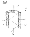
- den Randbereich einer abgewandelten Vakuumisolationsplatte in einer seitlichen Schnittansicht,
- Fig. 4
- zwei nebeneinanderliegende Vakuumisolationsplatten gemäß Fig. 3 in einer Teilansicht von vorne und
- Fig. 5
- zwei nebeneinanderliegende, erneut abgewandelte Vakuumisolationsplatten in einer der Fig. 4 entsprechenden Teilansicht von vorne.
- Das in Fig. 1 und 2 gezeigte Wandelement 13 umfaßt eine Vakuumisolationsplatte 38, eine äußere Holzschicht 71 und eine innere Holzschicht 25. Die äußere Holzschicht 71 kann aus Kerto, Holzwerkstoffplatten, Furnierplatten, Sperrholzplatten und/oder Vollholzplatten hergestellt sein. Die innere Holzschicht 25 kann aus KLH, HWP, VHP und/oder Dickholzplatten hergestellt sein, insbesondere aus Dickholzplatten mit statischer Tragfähigkeit. Vorteilhaft ist es, wenn die innere Holzschicht 25 aus statischen Lastabtrageplatten und die äußere Holzschicht 71 aus Fassadenplatten gebildet ist.
- Ferner sind die Vakuumisolationsplatte 38, die äußere Holzschicht 71 und die innere Holzschicht 25 durchdringende Verbindungselemente 49 vorgesehen, die als Schraubbolzen aus Metall ausgebildet sind. An den inneren Enden sind Muttern aufgeschraubt, die in entsprechenden Vertiefungen der inneren Holzschicht 25 versenkt sind. Die Außenseite der äußeren Holzschicht 71 ist durch eine diffusionsoffene Abdichtung 115 abgedeckt.
- Auf der äußeren Holzschicht 71 befindet sich eine Konterlattung 27, die ebenfalls von dem Verbindungselement 49 durchdrungen wird. Auf das äußere Ende des Verbindungselements 49 ist eine Mutter aufgeschraubt, die an der Außenseite der Konterlattung 27 anliegt.
- Auf der Konterlattung 27 befindet sich eine Lattung 34. Die Lattung 34 ist aus einem wärmedämmenden Material hergestellt, insbesondere einem wärmedämmenden Kunststoff, insbesondere einem wärmedämmenden Schaumkunststoff wie beispielsweise PUR. Sie besitzt auf ihrer zum Wandelement 13 weisenden Seite eine Aussparung für die Mutter, die auf das äußere Ende des Verbindungselements 49 aufgeschraubt ist. Auf der Lattung 34 ist eine Holzschalung 87 angebracht.
- Die Verbindungselemente 49 sind von jeweils einer Hülse 92 umgeben. Ferner ist im Bereich der Verbindungselemente 49 jeweils eine Abdeckscheibe 93 vorgesehen, die eine mittige Öffnung zum Durchtritt eines Verbindungselements 49 aufweist, die sich an den Enden der Hülse 92 nach außen anschließt und die den an die Hülse 92 anschließenden Bereich der Vakuumisolationsplatte 38 abdeckt. Die Abdeckscheiben 93 liegen an der Vakuumisolationsplatte 38 an, und zwar auf der der inneren Holzschicht 25 zugewandten Seite. Auf diese Weise liegen die Abdeckscheiben 93 zwischen der Vakuumisolationsplatte 38 und der inneren Holzschicht 29. Auf der anderen Seite der Vakuumisolationsplatte 38, also zwischen der Vakuumisolationsplatte 38 und der äußeren Holzschicht 71, können entsprechende Abdeckscheiben vorhanden sein (in der Zeichnung nicht dargestellt). Die Hülsen 92 und/oder die Abdeckscheiben 93 dienen zur Wärmeisolation der Verbindungselemente 49. Sie tragen dazu bei, daß durch die Verbindungselemente 49 keine Wärmebrücken gebildet werden.
- Zur Wärmeisolation dient ferner eine das Verbindungselement 49 umgebende Isolationsschicht 196. Der Außenumfang der Isolationsschicht 196 liegt an der Hülse 92 an. Die Isolationsschicht 196 kann vom einem Compriband gebildet werden.
- Die Vakuumisolationsplatte 38 umfaßt eine Vakuumdämmplatte 94, die auf beiden Seiten von jeweils einer Platte 95 aus Polyurethanschaum oder aus massivem Polyurethan umgeben ist. Die Außenseiten der Platten 95 sind von einer diffusionsdichten und gasdichten Umhüllung abgedeckt. Die Außenkanten der Vakuumdämmplatte 94 sind von einer druckstabilen Umrandung 96, insbesondere einem druckstabilen Konstruktionsschaum, umgeben. Die Umrandung 96 kann von einer Hochbarrierefolie umgeben sein. Die Hochbarrierefolie kann die Umrandung 96 und die äußeren Enden der Platten 95 einschließlich der Umhüllungen übergreifen, mit denen sie verbunden, insbesondere verklebt, sein kann.
- Nebeneinanderliegende Vakuumisolationsplatten können im Bereich der Durchführung für ein Verbindungselement 49, also im Bereich einer Hülse 92 für ein Verbindungselement 49, jeweils Aussparungen aufweisen, die einander gegenüberliegen und in denen sich die Hülse 92 befindet.
- Fig. 3 und 4 zeigen eine abgewandelte Ausführungsform, bei der mit der ersten Ausführungsform übereinstimmende Teile mit denselben Bezugszeichen versehen sind. Die Vakuumisolationsplatten 39, 39' umfassen jeweils eine Vakuumdämmplatte 94, die auf beiden Seiten von jeweils einer Platte 95 aus Polyurethanschaum oder aus massivem Polyurethan umgeben ist. Die Außenseiten der Platten 95 sind von einer diffusionsdichten und gasdichten Umhüllung 98 abgedeckt. Die Außenkanten der Vakuumdämmplatte 94 sind von einem Compriband 96' umgeben, das seinerseits von einem Butylband 97 umgeben ist. Das Butylband 97 übergreift das Compriband 96' und die äußeren Enden der Platten 95 einschließlich der Umhüllungen 98, mit denen es verbunden, insbesondere verklebt, ist. Das Compriband 96' ist gewölbt. Seine Stärke nimmt von der Mitte nach außen hin ab. Wenn benachbarte Vakuumisolationsplatten 39, 39' aneinandergelegt werden, werden die zugehörigen Compribänder 96' zusammengedrückt, wodurch ein Fugendichtschluß nebeneinanderliegender Vakuumisolationsplatten 39, 39' gewährleistet werden kann.
- In Fig. 4 sind Teilbereiche von zwei nebeneinanderliegenden Vakuumisolationsplatten 39, 39' dargestellt. Im Bereich der Durchführung für ein Verbindungselement 49, also im Bereich einer Hülse 92 für ein Verbindungselement 49, weisen die Vakuumisolationsplatten 39, 39' jeweils Aussparungen 99, 99' auf, die einander gegenüberliegen. Der Bereich zwischen den Aussparungen 99, 99' und der Hülse 92 wird ebenfalls durch die Compribänder 96' gefüllt.
- Die in Fig. 5 gezeigte Ausführungsform stimmt weitgehend mit derjenigen nach Fig. 4 überein, so daß gleiche Teile mit denselben Bezugszeichen versehen sind. Bei der Ausführungsform nach Fig. 5 sind keine Hülsen 92 und keine Isolationsschichten 196 vorhanden. Hier liegen die Compribänder 96' der Vakuumisolationsplatten 39, 39' unmittelbar an den Verbindungselementen 49 an.
- Bei dem die Isolationsschicht 196 bildenden Compriband und bei dem Compriband 96' handelt es sich vorzugsweise um ein vorkomprimiertes Fugendichtband aus offenzelligem Kunststoffschaum, insbesondere Polyurethan-Weichschaum, mit Polymerimprägnat oder mit einem Imprägnat auf Acrylatbasis.
- Die Wandelemente 13 bilden eine hinterlüftete Fassade, die demontierbar ist.
Claims (8)
- Wandelement, umfassend eine Vakuumisolationsplatte (38, 39, 39'), eine äußere Holzschicht (71) und/oder eine innere Holzschicht (25) und ein diese Teile durchdringendes Verbindungselement (49),
dadurch gekennzeichnet,
daß im Bereich des Verbindungselements (49) ein Isolationselement (34, 27, 92, 93, 196, 96') vorgesehen ist. - Wandelement nach Anspruch 1, dadurch gekennzeichnet, daß das Verbindungselement (49) an der Außenseite durch ein Isolationselement (34, 27) abgedeckt ist.
- Wandelement nach Anspruch 2, dadurch gekennzeichnet, daß das Isolationselement eine Lattung (34) und/oder eine Konterlattung (27) ist.
- Wandelement nach einem der vorhergehenden Ansprüche, gekennzeichnet durch eine das Verbindungselement (49) umgebende Hülse (92).
- Wandelement nach einem der vorhergehenden Ansprüche, gekennzeichnet durch eine oder mehrere Abdeckscheiben (93).
- Wandelement nach einem der vorhergehenden Ansprüche, gekennzeichnet durch eine das Verbindungselement (49) umgebende Isolationsschicht (196).
- Wandelement nach einem der vorhergehenden Ansprüche, gekennzeichnet durch ein die Außenkante der Vakuumisolationsplatte (39, 39') umgebendes Compriband (96').
- Fassade, gekennzeichnet durch Wandelemente (13) nach einem der Ansprüche 1 bis 7.
Applications Claiming Priority (1)
| Application Number | Priority Date | Filing Date | Title |
|---|---|---|---|
| DE102005027973A DE102005027973A1 (de) | 2005-06-16 | 2005-06-16 | Wandelement |
Publications (3)
| Publication Number | Publication Date |
|---|---|
| EP1734195A2 true EP1734195A2 (de) | 2006-12-20 |
| EP1734195A3 EP1734195A3 (de) | 2007-11-21 |
| EP1734195B1 EP1734195B1 (de) | 2010-08-18 |
Family
ID=37312454
Family Applications (1)
| Application Number | Title | Priority Date | Filing Date |
|---|---|---|---|
| EP06012115A Active EP1734195B1 (de) | 2005-06-16 | 2006-06-13 | Wandelement |
Country Status (3)
| Country | Link |
|---|---|
| EP (1) | EP1734195B1 (de) |
| AT (1) | ATE478207T1 (de) |
| DE (2) | DE102005027973A1 (de) |
Cited By (3)
| Publication number | Priority date | Publication date | Assignee | Title |
|---|---|---|---|---|
| EP2093340A1 (de) | 2008-02-22 | 2009-08-26 | Variotec Sandwichelemente GmbH & Co. KG | Verbundwärmedämmplatte und Wärmedämmverbundsystem |
| WO2016074658A1 (de) * | 2014-11-13 | 2016-05-19 | Fkn-Fassaden Gmbh+Co.Kg | Fassadensystem zur renovierung von altbauten mit feuerfesten fassadenelementen hoher wärme-dämmwirkung bei unebenem untergrund der gebäudewand und verfahren zu dessen herstellung |
| CN116497970A (zh) * | 2023-04-28 | 2023-07-28 | 中建八局装饰工程有限公司 | 弧形保温墙面结构及其施工方法 |
Families Citing this family (1)
| Publication number | Priority date | Publication date | Assignee | Title |
|---|---|---|---|---|
| DE202013005599U1 (de) | 2013-06-20 | 2014-09-22 | Variotec Gmbh & Co. Kg | Wandelement, Fassadenelement und Fassade mit einer Vakuumisolationsplatte |
Family Cites Families (3)
| Publication number | Priority date | Publication date | Assignee | Title |
|---|---|---|---|---|
| DE10225167B4 (de) * | 2002-06-06 | 2006-11-09 | Manuela Skorka-Dittrich | Raumhohes Außenwandelement |
| DE10333299B4 (de) * | 2003-07-22 | 2006-02-16 | Sto Ag | Wärmedämmsystem |
| DE10359005A1 (de) * | 2003-12-15 | 2005-07-14 | Va-Q-Tec Ag | Verbundwärmedämmplatte |
-
2005
- 2005-06-16 DE DE102005027973A patent/DE102005027973A1/de not_active Withdrawn
-
2006
- 2006-06-13 AT AT06012115T patent/ATE478207T1/de active
- 2006-06-13 DE DE502006007672T patent/DE502006007672D1/de active Active
- 2006-06-13 EP EP06012115A patent/EP1734195B1/de active Active
Cited By (3)
| Publication number | Priority date | Publication date | Assignee | Title |
|---|---|---|---|---|
| EP2093340A1 (de) | 2008-02-22 | 2009-08-26 | Variotec Sandwichelemente GmbH & Co. KG | Verbundwärmedämmplatte und Wärmedämmverbundsystem |
| WO2016074658A1 (de) * | 2014-11-13 | 2016-05-19 | Fkn-Fassaden Gmbh+Co.Kg | Fassadensystem zur renovierung von altbauten mit feuerfesten fassadenelementen hoher wärme-dämmwirkung bei unebenem untergrund der gebäudewand und verfahren zu dessen herstellung |
| CN116497970A (zh) * | 2023-04-28 | 2023-07-28 | 中建八局装饰工程有限公司 | 弧形保温墙面结构及其施工方法 |
Also Published As
| Publication number | Publication date |
|---|---|
| DE102005027973A1 (de) | 2006-12-21 |
| ATE478207T1 (de) | 2010-09-15 |
| EP1734195B1 (de) | 2010-08-18 |
| EP1734195A3 (de) | 2007-11-21 |
| DE502006007672D1 (de) | 2010-09-30 |
Similar Documents
| Publication | Publication Date | Title |
|---|---|---|
| EP1544367B1 (de) | Verbundwärmedämmplatte | |
| EP2183099B1 (de) | Wandaufbau und wärmedämmplatte | |
| EP2204513A2 (de) | Mehrschichtige Wärmedämmplatte und Verfahren zum Aufbau einer Wärmedammfassade | |
| DE19507732A1 (de) | Transparentes Bauelement, enthaltend mindestens eine faserverstärkte Aerogelplatte und/oder -matte | |
| EP2643534B2 (de) | Gebäudeumhüllungselement mit thermischem isolierelement | |
| EP2460945B1 (de) | Wärmedämmplatte mit eingelagerten Wärmedämmelementen geringer Wärmeleitfähigkeit sowie Bausatz dafür | |
| EP1734195B1 (de) | Wandelement | |
| DE69319256T2 (de) | Baueinheit | |
| AT12147U1 (de) | Wandelement | |
| EP0947638B1 (de) | Dämmplatte zur Verwendung an Aussenfassaden von Häusern | |
| EP2119841B1 (de) | Dämmelement und Verfahren zum Herstellen des Dämmelements | |
| DE10250665A1 (de) | Wandsystem | |
| DE3509514A1 (de) | Unterdachelement | |
| EP1734197B1 (de) | Wandelement mit zwischen zwei Betonfertigteilen angeordneten Vakuumisolierplatte | |
| EP2174776A1 (de) | Brandschutzeinrichtung | |
| DE10225167A1 (de) | Wandaufbau für Gebäudeaussenwände | |
| EP1734196A2 (de) | Durchdringungselement für ein Wandelement | |
| AT505575B1 (de) | Schweissvorrichtung mit nahtverfolgungssystem | |
| DE3308941C2 (de) | Plattenförmiges Wärmedämmelement | |
| DE2729232A1 (de) | Unbrennbares tragfaehiges leichtbau- element mit daemmstoffschicht ohne waermebruecken | |
| EP1734194A2 (de) | Wandelement und zugehöriges Ausgleichselement | |
| DE29922190U1 (de) | Dämmplattenelement für eine Wandungsverkleidung | |
| DE202006021154U1 (de) | Tür | |
| DE102011112644A1 (de) | Lichtdurchlässige Vakuumdämmplatte | |
| AT515886B1 (de) | Dämmplatte sowie Verfahren zur Herstellung einer Dämmplatte |
Legal Events
| Date | Code | Title | Description |
|---|---|---|---|
| PUAI | Public reference made under article 153(3) epc to a published international application that has entered the european phase |
Free format text: ORIGINAL CODE: 0009012 |
|
| AK | Designated contracting states |
Kind code of ref document: A2 Designated state(s): AT BE BG CH CY CZ DE DK EE ES FI FR GB GR HU IE IS IT LI LT LU LV MC NL PL PT RO SE SI SK TR |
|
| AX | Request for extension of the european patent |
Extension state: AL BA HR MK YU |
|
| PUAL | Search report despatched |
Free format text: ORIGINAL CODE: 0009013 |
|
| AK | Designated contracting states |
Kind code of ref document: A3 Designated state(s): AT BE BG CH CY CZ DE DK EE ES FI FR GB GR HU IE IS IT LI LT LU LV MC NL PL PT RO SE SI SK TR |
|
| AX | Request for extension of the european patent |
Extension state: AL BA HR MK YU |
|
| RIC1 | Information provided on ipc code assigned before grant |
Ipc: E04B 1/80 20060101AFI20061115BHEP Ipc: E04B 1/10 20060101ALI20071015BHEP |
|
| 17P | Request for examination filed |
Effective date: 20080207 |
|
| 17Q | First examination report despatched |
Effective date: 20080311 |
|
| AKX | Designation fees paid |
Designated state(s): AT BE BG CH CY CZ DE DK EE ES FI FR GB GR HU IE IS IT LI LT LU LV MC NL PL PT RO SE SI SK TR |
|
| AXX | Extension fees paid |
Extension state: MK Payment date: 20060613 Extension state: RS Payment date: 20060613 Extension state: HR Payment date: 20060613 Extension state: BA Payment date: 20060613 Extension state: AL Payment date: 20060613 |
|
| GRAP | Despatch of communication of intention to grant a patent |
Free format text: ORIGINAL CODE: EPIDOSNIGR1 |
|
| GRAC | Information related to communication of intention to grant a patent modified |
Free format text: ORIGINAL CODE: EPIDOSCIGR1 |
|
| GRAC | Information related to communication of intention to grant a patent modified |
Free format text: ORIGINAL CODE: EPIDOSCIGR1 |
|
| GRAS | Grant fee paid |
Free format text: ORIGINAL CODE: EPIDOSNIGR3 |
|
| GRAA | (expected) grant |
Free format text: ORIGINAL CODE: 0009210 |
|
| AK | Designated contracting states |
Kind code of ref document: B1 Designated state(s): AT BE BG CH CY CZ DE DK EE ES FI FR GB GR HU IE IS IT LI LT LU LV MC NL PL PT RO SE SI SK TR |
|
| AX | Request for extension of the european patent |
Extension state: AL BA HR MK RS |
|
| REG | Reference to a national code |
Ref country code: GB Ref legal event code: FG4D Free format text: NOT ENGLISH |
|
| REG | Reference to a national code |
Ref country code: CH Ref legal event code: NV Representative=s name: BOVARD AG PATENTANWAELTE Ref country code: CH Ref legal event code: EP |
|
| REG | Reference to a national code |
Ref country code: IE Ref legal event code: FG4D Free format text: LANGUAGE OF EP DOCUMENT: GERMAN |
|
| REF | Corresponds to: |
Ref document number: 502006007672 Country of ref document: DE Date of ref document: 20100930 Kind code of ref document: P |
|
| REG | Reference to a national code |
Ref country code: NL Ref legal event code: VDEP Effective date: 20100818 |
|
| LTIE | Lt: invalidation of european patent or patent extension |
Effective date: 20100818 |
|
| PG25 | Lapsed in a contracting state [announced via postgrant information from national office to epo] |
Ref country code: LT Free format text: LAPSE BECAUSE OF FAILURE TO SUBMIT A TRANSLATION OF THE DESCRIPTION OR TO PAY THE FEE WITHIN THE PRESCRIBED TIME-LIMIT Effective date: 20100818 Ref country code: FI Free format text: LAPSE BECAUSE OF FAILURE TO SUBMIT A TRANSLATION OF THE DESCRIPTION OR TO PAY THE FEE WITHIN THE PRESCRIBED TIME-LIMIT Effective date: 20100818 |
|
| PG25 | Lapsed in a contracting state [announced via postgrant information from national office to epo] |
Ref country code: PL Free format text: LAPSE BECAUSE OF FAILURE TO SUBMIT A TRANSLATION OF THE DESCRIPTION OR TO PAY THE FEE WITHIN THE PRESCRIBED TIME-LIMIT Effective date: 20100818 Ref country code: SI Free format text: LAPSE BECAUSE OF FAILURE TO SUBMIT A TRANSLATION OF THE DESCRIPTION OR TO PAY THE FEE WITHIN THE PRESCRIBED TIME-LIMIT Effective date: 20100818 Ref country code: PT Free format text: LAPSE BECAUSE OF FAILURE TO SUBMIT A TRANSLATION OF THE DESCRIPTION OR TO PAY THE FEE WITHIN THE PRESCRIBED TIME-LIMIT Effective date: 20101220 Ref country code: IS Free format text: LAPSE BECAUSE OF FAILURE TO SUBMIT A TRANSLATION OF THE DESCRIPTION OR TO PAY THE FEE WITHIN THE PRESCRIBED TIME-LIMIT Effective date: 20101218 Ref country code: CY Free format text: LAPSE BECAUSE OF FAILURE TO SUBMIT A TRANSLATION OF THE DESCRIPTION OR TO PAY THE FEE WITHIN THE PRESCRIBED TIME-LIMIT Effective date: 20100818 Ref country code: BG Free format text: LAPSE BECAUSE OF FAILURE TO SUBMIT A TRANSLATION OF THE DESCRIPTION OR TO PAY THE FEE WITHIN THE PRESCRIBED TIME-LIMIT Effective date: 20101118 |
|
| REG | Reference to a national code |
Ref country code: IE Ref legal event code: FD4D |
|
| PG25 | Lapsed in a contracting state [announced via postgrant information from national office to epo] |
Ref country code: GR Free format text: LAPSE BECAUSE OF FAILURE TO SUBMIT A TRANSLATION OF THE DESCRIPTION OR TO PAY THE FEE WITHIN THE PRESCRIBED TIME-LIMIT Effective date: 20101119 Ref country code: SE Free format text: LAPSE BECAUSE OF FAILURE TO SUBMIT A TRANSLATION OF THE DESCRIPTION OR TO PAY THE FEE WITHIN THE PRESCRIBED TIME-LIMIT Effective date: 20100818 Ref country code: LV Free format text: LAPSE BECAUSE OF FAILURE TO SUBMIT A TRANSLATION OF THE DESCRIPTION OR TO PAY THE FEE WITHIN THE PRESCRIBED TIME-LIMIT Effective date: 20100818 Ref country code: NL Free format text: LAPSE BECAUSE OF FAILURE TO SUBMIT A TRANSLATION OF THE DESCRIPTION OR TO PAY THE FEE WITHIN THE PRESCRIBED TIME-LIMIT Effective date: 20100818 |
|
| REG | Reference to a national code |
Ref country code: CH Ref legal event code: PFA Owner name: VARIOTEC SANDWICHELEMENTE GMBH & CO. KG Free format text: VARIOTEC SANDWICHELEMENTE GMBH & CO. KG#WEISSMARTER STRASSE 3#92318 NEUMARKT (DE) -TRANSFER TO- VARIOTEC SANDWICHELEMENTE GMBH & CO. KG#WEISSMARTER STRASSE 3#92318 NEUMARKT (DE) |
|
| PG25 | Lapsed in a contracting state [announced via postgrant information from national office to epo] |
Ref country code: IE Free format text: LAPSE BECAUSE OF FAILURE TO SUBMIT A TRANSLATION OF THE DESCRIPTION OR TO PAY THE FEE WITHIN THE PRESCRIBED TIME-LIMIT Effective date: 20100818 Ref country code: DK Free format text: LAPSE BECAUSE OF FAILURE TO SUBMIT A TRANSLATION OF THE DESCRIPTION OR TO PAY THE FEE WITHIN THE PRESCRIBED TIME-LIMIT Effective date: 20100818 |
|
| PG25 | Lapsed in a contracting state [announced via postgrant information from national office to epo] |
Ref country code: SK Free format text: LAPSE BECAUSE OF FAILURE TO SUBMIT A TRANSLATION OF THE DESCRIPTION OR TO PAY THE FEE WITHIN THE PRESCRIBED TIME-LIMIT Effective date: 20100818 Ref country code: CZ Free format text: LAPSE BECAUSE OF FAILURE TO SUBMIT A TRANSLATION OF THE DESCRIPTION OR TO PAY THE FEE WITHIN THE PRESCRIBED TIME-LIMIT Effective date: 20100818 Ref country code: RO Free format text: LAPSE BECAUSE OF FAILURE TO SUBMIT A TRANSLATION OF THE DESCRIPTION OR TO PAY THE FEE WITHIN THE PRESCRIBED TIME-LIMIT Effective date: 20100818 Ref country code: IT Free format text: LAPSE BECAUSE OF FAILURE TO SUBMIT A TRANSLATION OF THE DESCRIPTION OR TO PAY THE FEE WITHIN THE PRESCRIBED TIME-LIMIT Effective date: 20100818 Ref country code: EE Free format text: LAPSE BECAUSE OF FAILURE TO SUBMIT A TRANSLATION OF THE DESCRIPTION OR TO PAY THE FEE WITHIN THE PRESCRIBED TIME-LIMIT Effective date: 20100818 |
|
| PLBE | No opposition filed within time limit |
Free format text: ORIGINAL CODE: 0009261 |
|
| STAA | Information on the status of an ep patent application or granted ep patent |
Free format text: STATUS: NO OPPOSITION FILED WITHIN TIME LIMIT |
|
| PG25 | Lapsed in a contracting state [announced via postgrant information from national office to epo] |
Ref country code: ES Free format text: LAPSE BECAUSE OF FAILURE TO SUBMIT A TRANSLATION OF THE DESCRIPTION OR TO PAY THE FEE WITHIN THE PRESCRIBED TIME-LIMIT Effective date: 20101129 |
|
| 26N | No opposition filed |
Effective date: 20110519 |
|
| PGFP | Annual fee paid to national office [announced via postgrant information from national office to epo] |
Ref country code: CH Payment date: 20110627 Year of fee payment: 6 |
|
| PGFP | Annual fee paid to national office [announced via postgrant information from national office to epo] |
Ref country code: AT Payment date: 20110620 Year of fee payment: 6 |
|
| REG | Reference to a national code |
Ref country code: DE Ref legal event code: R097 Ref document number: 502006007672 Country of ref document: DE Effective date: 20110519 |
|
| BERE | Be: lapsed |
Owner name: VARIOTEC SANDWICHELEMENTE G.M.B.H. & CO. KG Effective date: 20110630 |
|
| GBPC | Gb: european patent ceased through non-payment of renewal fee |
Effective date: 20110613 |
|
| REG | Reference to a national code |
Ref country code: FR Ref legal event code: ST Effective date: 20120229 |
|
| PG25 | Lapsed in a contracting state [announced via postgrant information from national office to epo] |
Ref country code: BE Free format text: LAPSE BECAUSE OF NON-PAYMENT OF DUE FEES Effective date: 20110630 |
|
| REG | Reference to a national code |
Ref country code: DE Ref legal event code: R119 Ref document number: 502006007672 Country of ref document: DE Effective date: 20120103 |
|
| PG25 | Lapsed in a contracting state [announced via postgrant information from national office to epo] |
Ref country code: FR Free format text: LAPSE BECAUSE OF NON-PAYMENT OF DUE FEES Effective date: 20110630 Ref country code: DE Free format text: LAPSE BECAUSE OF NON-PAYMENT OF DUE FEES Effective date: 20120103 |
|
| PG25 | Lapsed in a contracting state [announced via postgrant information from national office to epo] |
Ref country code: GB Free format text: LAPSE BECAUSE OF NON-PAYMENT OF DUE FEES Effective date: 20110613 |
|
| REG | Reference to a national code |
Ref country code: CH Ref legal event code: PL |
|
| REG | Reference to a national code |
Ref country code: CH Ref legal event code: PL Ref country code: AT Ref legal event code: MM01 Ref document number: 478207 Country of ref document: AT Kind code of ref document: T Effective date: 20120613 |
|
| PG25 | Lapsed in a contracting state [announced via postgrant information from national office to epo] |
Ref country code: MC Free format text: LAPSE BECAUSE OF NON-PAYMENT OF DUE FEES Effective date: 20110630 Ref country code: LI Free format text: LAPSE BECAUSE OF NON-PAYMENT OF DUE FEES Effective date: 20120630 Ref country code: CH Free format text: LAPSE BECAUSE OF NON-PAYMENT OF DUE FEES Effective date: 20120630 |
|
| PG25 | Lapsed in a contracting state [announced via postgrant information from national office to epo] |
Ref country code: LU Free format text: LAPSE BECAUSE OF NON-PAYMENT OF DUE FEES Effective date: 20110613 |
|
| PG25 | Lapsed in a contracting state [announced via postgrant information from national office to epo] |
Ref country code: AT Free format text: LAPSE BECAUSE OF NON-PAYMENT OF DUE FEES Effective date: 20120613 |
|
| PG25 | Lapsed in a contracting state [announced via postgrant information from national office to epo] |
Ref country code: TR Free format text: LAPSE BECAUSE OF FAILURE TO SUBMIT A TRANSLATION OF THE DESCRIPTION OR TO PAY THE FEE WITHIN THE PRESCRIBED TIME-LIMIT Effective date: 20100818 |
|
| PG25 | Lapsed in a contracting state [announced via postgrant information from national office to epo] |
Ref country code: HU Free format text: LAPSE BECAUSE OF FAILURE TO SUBMIT A TRANSLATION OF THE DESCRIPTION OR TO PAY THE FEE WITHIN THE PRESCRIBED TIME-LIMIT Effective date: 20100818 |