EP1733993A1 - Elevator apparatus - Google Patents
Elevator apparatus Download PDFInfo
- Publication number
- EP1733993A1 EP1733993A1 EP04726642A EP04726642A EP1733993A1 EP 1733993 A1 EP1733993 A1 EP 1733993A1 EP 04726642 A EP04726642 A EP 04726642A EP 04726642 A EP04726642 A EP 04726642A EP 1733993 A1 EP1733993 A1 EP 1733993A1
- Authority
- EP
- European Patent Office
- Prior art keywords
- car
- main body
- disposed
- elevator apparatus
- guide rail
- Prior art date
- Legal status (The legal status is an assumption and is not a legal conclusion. Google has not performed a legal analysis and makes no representation as to the accuracy of the status listed.)
- Withdrawn
Links
Images


Classifications
-
- B—PERFORMING OPERATIONS; TRANSPORTING
- B66—HOISTING; LIFTING; HAULING
- B66B—ELEVATORS; ESCALATORS OR MOVING WALKWAYS
- B66B7/00—Other common features of elevators
- B66B7/02—Guideways; Guides
- B66B7/04—Riding means, e.g. Shoes, Rollers, between car and guiding means, e.g. rails, ropes
- B66B7/041—Riding means, e.g. Shoes, Rollers, between car and guiding means, e.g. rails, ropes including active attenuation system for shocks, vibrations
- B66B7/042—Riding means, e.g. Shoes, Rollers, between car and guiding means, e.g. rails, ropes including active attenuation system for shocks, vibrations with rollers, shoes
-
- B—PERFORMING OPERATIONS; TRANSPORTING
- B66—HOISTING; LIFTING; HAULING
- B66B—ELEVATORS; ESCALATORS OR MOVING WALKWAYS
- B66B11/00—Main component parts of lifts in, or associated with, buildings or other structures
- B66B11/02—Cages, i.e. cars
-
- B—PERFORMING OPERATIONS; TRANSPORTING
- B66—HOISTING; LIFTING; HAULING
- B66B—ELEVATORS; ESCALATORS OR MOVING WALKWAYS
- B66B7/00—Other common features of elevators
- B66B7/02—Guideways; Guides
- B66B7/04—Riding means, e.g. Shoes, Rollers, between car and guiding means, e.g. rails, ropes
Definitions
- the present invention relates to an elevator apparatus in which a gap between a doorsill of a car door and a doorsill of a landing door is reduced by displacing a car toward a landing.
- Conventional elevator apparatuses such as that described in Japanese Patent Laid-Open No. 2000-229773 (Gazette), for example, include: an elongated blocking member disposed on a car so as to block a gap between a doorsill of a car door and a doorsill of a landing door by pivoting; and a driving mechanism coupled between the blocking member and a car door motor so as to pivot the blocking member interdependently with opening and closing actions of the car door.
- the blocking member itself must be highly rigid in order to support heavy loads such as freight carts, hospital stretchers, etc., when they act directly on the blocking member, and one problem has been that the driving force of the car door motor must be increased in preparation for such large loads acting on the blocking member, increasing the size of the motor and also raising manufacturing costs.
- the present invention aims to solve the above problems and an object of the present invention is to provide an elevator apparatus eliminating a need for a blocking member, and also eliminating a need for an enlarged car door motor having a large driving force.
- an elevator apparatus including: a car main body guided by a guide rail so as to ascend and descend inside a hoistway; a car frame disposed outside the car main body; a guide shoe fixed to the car frame so as to move along the guide rail; and a pressing means for pressing the guide shoe toward the guide rail, wherein: the car main body is displaced toward a landing by a reaction force from the guide rail when the guide shoe is pressed against the guide rail by actuation of the pressing means.
- Figure 1 is a front elevation showing an elevator apparatus according to Embodiment 1 of the present invention. Please note that first depth direction rollers have been omitted from Figure 1.
- a car 2 suspended by a main rope 1 and moved vertically is disposed in a hoistway of the elevator apparatus.
- the car 2 includes: a car main body 3; a car frame 4 disposed outside the car main body 3; and rubber vibration isolators 20 disposed between the car main body 3 or the car frame 4 so as to suppress vibration of the car main body 3.
- Roller guides 5 constituting a guide shoe are fixed to each of four corners of the car frame 4.
- Each of the roller guides 5, as shown in Figure 2 includes: a lateral roller 7 for restricting movement of the car 2 in left and right directions (when viewed facing a car door 23 disposed on a front surface of the car main body 3) ; and a first depth direction roller 8 and a second depth direction roller 9 for restricting movement of the car 2 in a depth direction (toward the car 2 and toward a landing when viewed facing the car door 23), and the roller guides 5 are placed in contact with a pair of T-shaped guide rails 6 extending vertically on wall surfaces of the hoistway from each of three directions.
- Pressing means 10 for pressing the first depth direction rollers 8 toward the guide rails 6, as shown in Figure 3, are disposed on each of the first depth direction rollers 8 near the landing. These pressing means 10 are disposed on each of the first depth direction rollers 8 of the roller guides 5 at the four corners of the car frame 4.
- a generally L-shaped lever 11 is disposed such that a base end portion is pivotable around a pivot point 15 on the car frame 4.
- a leading end portion of the lever 11 is fixed to a shaft 21 of the first depth direction roller 8.
- a first end portion of an arm 12 is fixed to an intermediate portion of the lever 11.
- An expandable and contractible driving portion 13 fixed to the car frame 4 is placed in contact with a second end portion of the arm 12.
- a spring 14 for forcing an end portion of the lever 11 toward the guide rail 6 so as to place the first depth direction roller 8 in constant contact with the guide rail 6 is disposed in a vicinity of the shaft 21.
- the driving portion 13 is constituted by a voice coil motor made up of a coil and a magnet.
- other methods such as electromagnetic attraction, etc., are also acceptable.
- the car 2 is subjected to reaction forces from the guide rails 6 against the pressure from the four first depth direction rollers 8, whereby the car 2 displaces horizontally and approaches a landing 22, narrowing a gap between a doorsill of the car door 23 and a doorsill of a landing door (not shown), as shown in Figure 5.
- the pressing means 10 was disposed on each of the first depth direction rollers 8 of the roller guides 5 on the four corners of the car frame 4, but the pressing means may also be disposed in two places, on each of the right and left depth direction rollers near the car door doorsill.
- Figure 6 is a partial cross section showing an elevator apparatus according to Embodiment 2 of the present invention.
- an optical sensor 25 constituting a distance sensor for detecting a gap distance between a car main body 3 and a landing 22 is disposed on a car floor 24 of the car main body 3 near the landing 22.
- the gap distance between the main body 3 and the landing 22 is detected by the optical sensor 25, and driving of the driving portion 13 is stopped by a signal from the optical sensor 25 before the car main body 3 collides with the landing 22.
- the distance sensor may also be a mechanical sensor such as a micro switch, for example, instead of an optical sensor.
- the distance sensor may also be mounted to the landing so as to face the car floor 24.
- Figure 7 is a partial cross section showing an elevator apparatus according to Embodiment 3 of the present invention.
- a pressing means 26 is disposed between the car frame 4 and a car floor 24.
- a first magnetic pole 27 and a second magnetic pole 29 are mounted to the car frame 4.
- a first coil 28 facing the first magnetic pole 27 and a second coil 30 facing the second magnetic pole 29 are each mounted to the car floor 24.
- a first sensor 31 for detecting a distance between the first magnetic pole 27 and the first coil 28 is mounted to the first coil 28.
- a second sensor 32 for detecting a distance between the second magnetic pole 29 and the second coil 30 is mounted to the second coil 30.
- the car floor 24 and the car frame 4 are each connected at two end portions by deforming members 33 having a U-shaped cross section.
- a first coil and a second coil may also be mounted to a car frame, and a first magnetic pole and a second magnetic pole mounted to a car floor.
- an electric current is passed through the first coil 28, attracting the first magnetic pole 27 toward the first coil 28 as indicated by arrow C, and pressing the first depth direction rollers 8 toward the guide rails 6 through the car frame 4.
- the guide rails 6 are fixed to the wall surfaces of a hoistway, the car 2 is subjected to reaction forces from the guide rails 6 against the pressure through the first depth direction rollers 8 and the car frame 4, whereby the car 2 moves and approaches a landing 22, narrowing a gap between a doorsill of a car door 23 and a doorsill of a landing door.
- the passage of electric current to the first coil 28 and the second coil 30 is switched on and off by signals from the first sensor 31 and the second sensor 32 to ensure appropriate gaps between the doorsill of the car door and the doorsill of the landing door when the car door 23 is in an open state and a closed state.
Landscapes
- Engineering & Computer Science (AREA)
- Civil Engineering (AREA)
- Mechanical Engineering (AREA)
- Structural Engineering (AREA)
- Elevator Door Apparatuses (AREA)
- Lift-Guide Devices, And Elevator Ropes And Cables (AREA)
Abstract
An elevator apparatus includes: a car main body guided by a guide rail so as to ascend and descend inside a hoistway; a car frame disposed outside the car main body; a guide shoe fixed to the car frame so as to move along the guide rail; and a pressing means for pressing the guide shoe toward the guide rail. The car main body is displaced toward a landing by a reaction force from the guide rail when the guide shoe is pressed against the guide rail by actuation of the pressing means.
Description
- The present invention relates to an elevator apparatus in which a gap between a doorsill of a car door and a doorsill of a landing door is reduced by displacing a car toward a landing.
- Conventional elevator apparatuses such as that described in
Japanese Patent Laid-Open No. 2000-229773 - In such elevator apparatuses, even if a user getting on or off the car happens to drop something, it is prevented from falling through the gap into the hoistway because the blocking member pivots synchronously with the door opening action of the car on arrival at a floor so as to block the gap between the doorsill of the car door and the doorsill of the landing door.
- However, in such configurations, the blocking member itself must be highly rigid in order to support heavy loads such as freight carts, hospital stretchers, etc., when they act directly on the blocking member, and one problem has been that the driving force of the car door motor must be increased in preparation for such large loads acting on the blocking member, increasing the size of the motor and also raising manufacturing costs.
- The present invention aims to solve the above problems and an object of the present invention is to provide an elevator apparatus eliminating a need for a blocking member, and also eliminating a need for an enlarged car door motor having a large driving force.
- In order to achieve the above object, according to one aspect of the present invention, there is provided an elevator apparatus including: a car main body guided by a guide rail so as to ascend and descend inside a hoistway; a car frame disposed outside the car main body; a guide shoe fixed to the car frame so as to move along the guide rail; and a pressing means for pressing the guide shoe toward the guide rail, wherein: the car main body is displaced toward a landing by a reaction force from the guide rail when the guide shoe is pressed against the guide rail by actuation of the pressing means.
-
- Figure 1 is a front elevation showing an elevator apparatus according to Embodiment 1 of the present invention;
- Figure 2 is a plan showing a roller guide from Figure 1;
- Figure 3 is a front elevation of a pressing means for pressing a first depth direction roller from Figure 2;
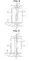
- Figure 4 is a side elevation showing a first service state of the elevator apparatus in Figure 1;
- Figure 5 is a side elevation showing a second service state of the elevator apparatus in Figure 1;
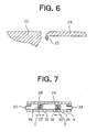
- Figure 6 is a partial cross section showing an elevator apparatus according to
Embodiment 2 of the present invention; and - Figure 7 is a partial cross section showing an elevator apparatus according to
Embodiment 3 of the present invention. - Preferred embodiments of the present invention will now be explained with reference to the drawings, and members and portions identical or equivalent in each of the embodiments will be given identical numbering.
- Figure 1 is a front elevation showing an elevator apparatus according to Embodiment 1 of the present invention. Please note that first depth direction rollers have been omitted from Figure 1.
- A
car 2 suspended by a main rope 1 and moved vertically is disposed in a hoistway of the elevator apparatus. Thecar 2 includes: a carmain body 3; acar frame 4 disposed outside the carmain body 3; andrubber vibration isolators 20 disposed between the carmain body 3 or thecar frame 4 so as to suppress vibration of the carmain body 3.Roller guides 5 constituting a guide shoe are fixed to each of four corners of thecar frame 4. - Each of the
roller guides 5, as shown in Figure 2, includes: alateral roller 7 for restricting movement of thecar 2 in left and right directions (when viewed facing acar door 23 disposed on a front surface of the car main body 3) ; and a firstdepth direction roller 8 and a seconddepth direction roller 9 for restricting movement of thecar 2 in a depth direction (toward thecar 2 and toward a landing when viewed facing the car door 23), and theroller guides 5 are placed in contact with a pair of T-shaped guide rails 6 extending vertically on wall surfaces of the hoistway from each of three directions. - Pressing means 10 for pressing the first
depth direction rollers 8 toward theguide rails 6, as shown in Figure 3, are disposed on each of the firstdepth direction rollers 8 near the landing. These pressingmeans 10 are disposed on each of the firstdepth direction rollers 8 of theroller guides 5 at the four corners of thecar frame 4. - In the
pressing means 10, a generally L-shaped lever 11 is disposed such that a base end portion is pivotable around apivot point 15 on thecar frame 4. A leading end portion of the lever 11 is fixed to ashaft 21 of the firstdepth direction roller 8. A first end portion of anarm 12 is fixed to an intermediate portion of the lever 11. An expandable andcontractible driving portion 13 fixed to thecar frame 4 is placed in contact with a second end portion of thearm 12. Aspring 14 for forcing an end portion of the lever 11 toward theguide rail 6 so as to place the firstdepth direction roller 8 in constant contact with theguide rail 6 is disposed in a vicinity of theshaft 21. Thedriving portion 13 is constituted by a voice coil motor made up of a coil and a magnet. Here, other methods such as electromagnetic attraction, etc., are also acceptable. - Next, action of an elevator apparatus having the above configuration will be explained.
- As shown in Figure 4, when the
car 2 arrives at a service floor, a door opening action is started by driving a door motor. Then, an electric current flows through thedriving portion 13, driving thedriving portion 13, whereby thedriving portion 13 extends in the direction of arrow A as shown in Figure 3, and the lever 11 integrated with thearm 12 begins to pivot around thepivot point 15 in a counterclockwise direction, pressing the firstdepth direction rollers 8 toward therespective guide rail 6 as indicated by arrow B. Here, because theguide rails 6 are fixed to the wall surfaces of the hoistway, thecar 2 is subjected to reaction forces from theguide rails 6 against the pressure from the four firstdepth direction rollers 8, whereby thecar 2 displaces horizontally and approaches alanding 22, narrowing a gap between a doorsill of thecar door 23 and a doorsill of a landing door (not shown), as shown in Figure 5. - On the other hand, as the doors are being closed, the
driving portion 13 contracts, the lever 11 integrated with thearm 12 pivots in a clockwise direction, and the pressure pressing the firstdepth direction roller 8 toward theguide rail 6 decreases. Consequently, because the reaction forces from theguide rails 6 toward thecar 2 against the pressure are also reduced, thecar 2 displaces horizontally away from thelanding 22, widening the gap between the doorsill of thecar door 23 and the doorsill of the landing door. - As explained above, using an elevator apparatus of this kind, because the
car 2 is displaced toward thelanding 22 by a reaction force from theguide rails 6 when the firstdepth direction rollers 8 press on theguide rails 6 due to actuation of thepressing means 10, the need for the blocking member required conventionally is eliminated, and problems expressly requiring an enlarged car door motor having a large driving force in anticipation of large loads acting on a blocking member can be solved. - Moreover, in the above embodiment, the
pressing means 10 was disposed on each of the firstdepth direction rollers 8 of theroller guides 5 on the four corners of thecar frame 4, but the pressing means may also be disposed in two places, on each of the right and left depth direction rollers near the car door doorsill. - Figure 6 is a partial cross section showing an elevator apparatus according to
Embodiment 2 of the present invention. - In this elevator apparatus, an
optical sensor 25 constituting a distance sensor for detecting a gap distance between a carmain body 3 and alanding 22 is disposed on acar floor 24 of the carmain body 3 near thelanding 22. - In this elevator apparatus, the gap distance between the
main body 3 and thelanding 22 is detected by theoptical sensor 25, and driving of thedriving portion 13 is stopped by a signal from theoptical sensor 25 before the carmain body 3 collides with thelanding 22. - Moreover, the distance sensor may also be a mechanical sensor such as a micro switch, for example, instead of an optical sensor.
- The distance sensor may also be mounted to the landing so as to face the
car floor 24. - Figure 7 is a partial cross section showing an elevator apparatus according to
Embodiment 3 of the present invention. - In this elevator apparatus, a
pressing means 26 is disposed between thecar frame 4 and acar floor 24. In this pressing means 26, a firstmagnetic pole 27 and a secondmagnetic pole 29 are mounted to thecar frame 4. Afirst coil 28 facing the firstmagnetic pole 27 and asecond coil 30 facing the secondmagnetic pole 29 are each mounted to thecar floor 24. Afirst sensor 31 for detecting a distance between the firstmagnetic pole 27 and thefirst coil 28 is mounted to thefirst coil 28. Asecond sensor 32 for detecting a distance between the secondmagnetic pole 29 and thesecond coil 30 is mounted to thesecond coil 30. Thecar floor 24 and thecar frame 4 are each connected at two end portions by deformingmembers 33 having a U-shaped cross section. - Moreover, a first coil and a second coil may also be mounted to a car frame, and a first magnetic pole and a second magnetic pole mounted to a car floor.
- In an elevator apparatus according to this embodiment, when a
car 2 arrives at a service floor, an electric current is passed through thefirst coil 28, attracting the firstmagnetic pole 27 toward thefirst coil 28 as indicated by arrow C, and pressing the firstdepth direction rollers 8 toward theguide rails 6 through thecar frame 4. Here, because theguide rails 6 are fixed to the wall surfaces of a hoistway, thecar 2 is subjected to reaction forces from theguide rails 6 against the pressure through the firstdepth direction rollers 8 and thecar frame 4, whereby thecar 2 moves and approaches alanding 22, narrowing a gap between a doorsill of acar door 23 and a doorsill of a landing door. - On the other hand, as the doors are being closed, an electric current is passed through the
second coil 30, attracting the secondmagnetic pole 29 toward thesecond coil 30 as indicated by arrow D and reducing the force pressing the firstdepth direction rollers 8 toward theguide rails 6, and because the reaction force against the pressure from theguide rails 6 toward thecar 2 is consequently also reduced, thecar 2 separates from thelanding 22, widening the gap between the doorsill of thecar door 23 and the doorsill of the landing door. - Moreover, the passage of electric current to the
first coil 28 and thesecond coil 30 is switched on and off by signals from thefirst sensor 31 and thesecond sensor 32 to ensure appropriate gaps between the doorsill of the car door and the doorsill of the landing door when thecar door 23 is in an open state and a closed state. - Moreover, in each of the above embodiments, cases in which roller guides are used have been explained, but of course the present invention can also be applied to sliding guides.
Claims (7)
- An elevator apparatus comprising:a car main body guided by a guide rail so as to ascend and descend inside a hoistway;a car frame disposed outside said car main body;a guide shoe fixed to said car frame so as to move along said guide rail; anda pressing means for pressing said guide shoe toward said guide rail,wherein:said car main body is displaced toward a landing by a reaction force from said guide rail when said guide shoe is pressed against said guide rail by actuation of said pressing means.
- The elevator apparatus according to Claim 1, wherein:said pressing means is disposed between said car frame and said guide shoe.
- The elevator apparatus according to Claim 1, wherein:said pressing means is disposed between said car main body and said car frame.
- The elevator apparatus according to any one of Claims 1 through 3,
wherein:a distance sensor for sensing a gap distance between said car main body and said landing is disposed between said car main body and said landing such that said car main body is stopped before colliding with said landing by a signal from said distance sensor. - The elevator apparatus according to Claim 2, wherein:said pressing means comprises:a lever having a base end portion disposed pivotably on said car frame and a leading end portion disposed pivotably on said guide shoe;an arm having a first end portion connected to said lever; anda driving portion disposed between a second end portion of said arm and said car frame, said driving portion pressing said guide shoe against said guide rail by extending to pivot said lever by means of said arm.
- The elevator apparatus according to Claim 3, wherein:said pressing means comprises:a magnetic pole disposed on a first part selected from said car frame and a car floor of said car main body; anda coil disposed so as to face said magnetic pole on a second part selected from said car frame and said car floor, andan attractive force is generated between said coil and said magnetic pole by passage of an electric current.
- The elevator apparatus according to Claim 6, wherein:a distance sensor for sensing a gap distance between said coil and said magnetic pole is disposed on a first part selected from said coil and said magnetic pole such that said car main body is stopped before colliding with said landing by a signal from said distance sensor.
Applications Claiming Priority (1)
| Application Number | Priority Date | Filing Date | Title |
|---|---|---|---|
| PCT/JP2004/005063 WO2005100226A1 (en) | 2004-04-08 | 2004-04-08 | Elevator apparatus |
Publications (2)
| Publication Number | Publication Date |
|---|---|
| EP1733993A1 true EP1733993A1 (en) | 2006-12-20 |
| EP1733993A4 EP1733993A4 (en) | 2009-11-25 |
Family
ID=35149898
Family Applications (1)
| Application Number | Title | Priority Date | Filing Date |
|---|---|---|---|
| EP04726642A Withdrawn EP1733993A4 (en) | 2004-04-08 | 2004-04-08 | ELEVATOR EQUIPMENT |
Country Status (4)
| Country | Link |
|---|---|
| EP (1) | EP1733993A4 (en) |
| JP (1) | JPWO2005100226A1 (en) |
| CN (1) | CN1787960A (en) |
| WO (1) | WO2005100226A1 (en) |
Cited By (1)
| Publication number | Priority date | Publication date | Assignee | Title |
|---|---|---|---|---|
| EP3517474A1 (en) * | 2018-01-30 | 2019-07-31 | KONE Corporation | Method and an elevator control unit for controlling a doorstep gap of an elevator and an elevator |
Families Citing this family (6)
| Publication number | Priority date | Publication date | Assignee | Title |
|---|---|---|---|---|
| WO2011076532A1 (en) * | 2009-12-21 | 2011-06-30 | Inventio Ag | Elevator having a counterweight |
| CN103591903A (en) * | 2013-11-22 | 2014-02-19 | 苏州大学 | System and method for measuring distance between elevator lift car sill and well inner surface |
| JP6560000B2 (en) * | 2015-04-02 | 2019-08-14 | 株式会社日立製作所 | Elevator guide device |
| CN111703998B (en) * | 2020-05-29 | 2024-07-05 | 上海领升自动化系统有限公司 | A hoist with precise parking function |
| JP7251588B1 (en) | 2021-09-27 | 2023-04-04 | フジテック株式会社 | elevator |
| CN114291678B (en) * | 2021-12-30 | 2024-05-03 | 成都科达光电技术有限责任公司 | Method for judging safety state of construction elevator by using multifunctional construction elevator safety monitoring equipment |
Family Cites Families (7)
| Publication number | Priority date | Publication date | Assignee | Title |
|---|---|---|---|---|
| JPS514057U (en) * | 1974-06-24 | 1976-01-13 | ||
| JPH01288593A (en) * | 1988-05-16 | 1989-11-20 | Mitsubishi Electric Corp | Movable cage floor device |
| DE58904201D1 (en) * | 1988-11-02 | 1993-06-03 | Inventio Ag | METHOD AND DEVICE FOR EXERCISING THE METHOD FOR VIBRATION ABSORBING ON CABS IN HIGH SPEED CABINS. |
| JPH06255948A (en) * | 1993-03-04 | 1994-09-13 | Toshiba Corp | Self-traveling elevator |
| JP4161063B2 (en) * | 1999-10-22 | 2008-10-08 | 三菱電機株式会社 | Elevator device and guide device for elevator device |
| JP2002179373A (en) * | 2000-12-14 | 2002-06-26 | Mitsubishi Electric Corp | Elevator equipment |
| JP4245389B2 (en) * | 2003-03-25 | 2009-03-25 | 東芝エレベータ株式会社 | Elevator threshold system |
-
2004
- 2004-04-08 JP JP2006519116A patent/JPWO2005100226A1/en active Pending
- 2004-04-08 EP EP04726642A patent/EP1733993A4/en not_active Withdrawn
- 2004-04-08 CN CN200480013210.9A patent/CN1787960A/en active Pending
- 2004-04-08 WO PCT/JP2004/005063 patent/WO2005100226A1/en not_active Ceased
Cited By (1)
| Publication number | Priority date | Publication date | Assignee | Title |
|---|---|---|---|---|
| EP3517474A1 (en) * | 2018-01-30 | 2019-07-31 | KONE Corporation | Method and an elevator control unit for controlling a doorstep gap of an elevator and an elevator |
Also Published As
| Publication number | Publication date |
|---|---|
| WO2005100226A1 (en) | 2005-10-27 |
| CN1787960A (en) | 2006-06-14 |
| EP1733993A4 (en) | 2009-11-25 |
| JPWO2005100226A1 (en) | 2007-08-30 |
Similar Documents
| Publication | Publication Date | Title |
|---|---|---|
| CN112867687B (en) | Emergency stop device and elevator | |
| US12280984B2 (en) | Elevator system | |
| CN1795137B (en) | Emergency stop device of elevator | |
| US20200207581A1 (en) | Elevator safety device | |
| WO2007080626A1 (en) | Elevator device | |
| EP1733993A1 (en) | Elevator apparatus | |
| US11235950B2 (en) | Elevator safety gear actuation device | |
| KR102211112B1 (en) | Elevator safety gear actuation device | |
| EP1627842A1 (en) | Door device of elevator | |
| CN116081428B (en) | Safety braking system | |
| JP4913145B2 (en) | Elevator door equipment | |
| CN102264625B (en) | elevator door control | |
| KR100668913B1 (en) | Elevator device | |
| JP2001322786A (en) | Elevator car soundproofing | |
| JP6502864B2 (en) | Passenger car door airtight apparatus and elevator apparatus | |
| SG189647A1 (en) | Elevator apparatus | |
| KR20210002990A (en) | Apparatus for preventing insertion of hands for elevator door | |
| JP2003081558A (en) | Elevator device for connecting bridge | |
| KR100903469B1 (en) | Elevator device | |
| KR20230150721A (en) | Apparatus for reducing elevator car bounce | |
| JP2017088372A (en) | Elevator apparatus | |
| CN116924182A (en) | Device for reducing shaking of elevator car | |
| HK1236021A1 (en) | Elevator apparatus | |
| JP2005075522A (en) | Elevator | |
| HK1141501B (en) | Braking device for elevator |
Legal Events
| Date | Code | Title | Description |
|---|---|---|---|
| PUAI | Public reference made under article 153(3) epc to a published international application that has entered the european phase |
Free format text: ORIGINAL CODE: 0009012 |
|
| 17P | Request for examination filed |
Effective date: 20050908 |
|
| AK | Designated contracting states |
Kind code of ref document: A1 Designated state(s): DE |
|
| RBV | Designated contracting states (corrected) |
Designated state(s): DE |
|
| DAX | Request for extension of the european patent (deleted) | ||
| RBV | Designated contracting states (corrected) |
Designated state(s): DE |
|
| STAA | Information on the status of an ep patent application or granted ep patent |
Free format text: STATUS: THE APPLICATION HAS BEEN WITHDRAWN |
|
| A4 | Supplementary search report drawn up and despatched |
Effective date: 20091023 |
|
| 18W | Application withdrawn |
Effective date: 20091113 |