EP1733862A1 - Mold clamping apparatus of injection molding machine and method of adjusting effective length of tie bar - Google Patents
Mold clamping apparatus of injection molding machine and method of adjusting effective length of tie bar Download PDFInfo
- Publication number
- EP1733862A1 EP1733862A1 EP05018922A EP05018922A EP1733862A1 EP 1733862 A1 EP1733862 A1 EP 1733862A1 EP 05018922 A EP05018922 A EP 05018922A EP 05018922 A EP05018922 A EP 05018922A EP 1733862 A1 EP1733862 A1 EP 1733862A1
- Authority
- EP
- European Patent Office
- Prior art keywords
- mold clamping
- tie bar
- tie bars
- mold
- tie
- Prior art date
- Legal status (The legal status is an assumption and is not a legal conclusion. Google has not performed a legal analysis and makes no representation as to the accuracy of the status listed.)
- Granted
Links
- 238000001746 injection moulding Methods 0.000 title claims abstract description 15
- 238000000034 method Methods 0.000 title claims description 18
- 238000010438 heat treatment Methods 0.000 claims abstract description 5
- 239000000758 substrate Substances 0.000 description 16
- 238000000465 moulding Methods 0.000 description 6
- 238000009826 distribution Methods 0.000 description 5
- 238000002474 experimental method Methods 0.000 description 4
- 238000010276 construction Methods 0.000 description 3
- 230000003247 decreasing effect Effects 0.000 description 2
- 238000004519 manufacturing process Methods 0.000 description 2
- 239000000463 material Substances 0.000 description 2
- 238000003825 pressing Methods 0.000 description 2
- 241001155961 Baris Species 0.000 description 1
- 238000010586 diagram Methods 0.000 description 1
- 239000011295 pitch Substances 0.000 description 1
Images


Classifications
-
- B—PERFORMING OPERATIONS; TRANSPORTING
- B29—WORKING OF PLASTICS; WORKING OF SUBSTANCES IN A PLASTIC STATE IN GENERAL
- B29C—SHAPING OR JOINING OF PLASTICS; SHAPING OF MATERIAL IN A PLASTIC STATE, NOT OTHERWISE PROVIDED FOR; AFTER-TREATMENT OF THE SHAPED PRODUCTS, e.g. REPAIRING
- B29C45/00—Injection moulding, i.e. forcing the required volume of moulding material through a nozzle into a closed mould; Apparatus therefor
- B29C45/17—Component parts, details or accessories; Auxiliary operations
- B29C45/1751—Adjustment means allowing the use of moulds of different thicknesses
-
- B—PERFORMING OPERATIONS; TRANSPORTING
- B29—WORKING OF PLASTICS; WORKING OF SUBSTANCES IN A PLASTIC STATE IN GENERAL
- B29C—SHAPING OR JOINING OF PLASTICS; SHAPING OF MATERIAL IN A PLASTIC STATE, NOT OTHERWISE PROVIDED FOR; AFTER-TREATMENT OF THE SHAPED PRODUCTS, e.g. REPAIRING
- B29C45/00—Injection moulding, i.e. forcing the required volume of moulding material through a nozzle into a closed mould; Apparatus therefor
- B29C45/17—Component parts, details or accessories; Auxiliary operations
- B29C45/76—Measuring, controlling or regulating
- B29C45/7653—Measuring, controlling or regulating mould clamping forces
Definitions
- the present invention relates to a mold clamping apparatus of an injection molding machine and to a method of adjusting effective lengths of tie bars.
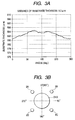
- FIG. 6 is a view schematically showing a related molding clamping apparatus, in which FIG. 6A is a front view thereof, and FIG. 6B is a sectional view taken along a line XI-XI of FIG. 6A.
- the mold clamping apparatus 101 shown in FIG. 6 includes a fixed platen 106 to which a fixed-side mold 106a is attached, a movable platen 107 to which a moving-side mold 107a is attached and which is capable of moving with respect to the fixed platen 106, and a mold clamping housing 108 which is connected to the movable platen 107 through a toggle link type or direct hydraulic pressing mechanism 111.
- Four tie bars 102A to 102D are provided between the fixed platen 106 and the mold clamping housing 108, and the movable platen 107 can move along the tie bars.
- each of the tie bars 102A to 102D Male screws are formed at both end portions of each of the tie bars 102A to 102D, tie bar nuts 110 are screwed to the male screws at the side of the fixed platen 106, and female screws formed in mold thickness adjusting units 109 are screwed to the male screws at the side of the mold clamping housing 108.
- the effective length of each of the tie bars can be adjusted by varying the distance between the tie bar nuts 110 and the mold thickness adjusting units 109.
- a first method of varying the distance between the tie bar nuts 110 and the mold thickness adjusting units 109 by providing die height adjusting nuts to the mold thickness adjusting units 109 and by rotating the die height adjusting nuts has been known.
- a second method of varying the distance between the tie bar nuts 110 and the mold thickness adjusting units 109 by forming the male screws formed at both end portions of each of the tie bars as screws inversed to each other or by forming pitches thereof different to each other, and by rotating only the tie bars in a state in which the tie bar nuts 110 and the mold thickness adjusting units 109 are fixed has been known.
- the first method is disclosed in Japanese Patent No. 3549280 .
- the balance of the extended amount of the four tie bars 102A to 102D when the mold clamping force is generated by operating the mold clamping apparatus 101, and furthermore the balance of the mold clamping force acting on the molds can be adjusted by adjusting individually the effective length of each of the tie bars by the above-described methods.
- the first method has following problems.
- the second method has following problems.
- a mold clamping apparatus of an injection molding machine comprises a fixed platen to which a fixed-side mold is attached, a mold clamping housing, at least one of tie bar provided between the fixed platen and the mold clamping housing, a movable platen to which a moving-side mold is attached and which is capable of moving with respect to the fixed platen along the tie bar, a heater for heating the tie bar, a sensor for sensing a temperature of a portion heated by the heater, the heater and the sensor being provided to each tie bar, and a temperature adjustor which is connected to the heater and the sensor and controls the temperature of the heated portion of the tie bar.
- the tie bar is heated by the heater.
- the tie bar heated by the heater is adjacent to thin portions of a molded product injected in the mold.
- the effective lengths of the tie bars themselves are varied due to the thermal expansion depending on the heated temperature.
- the effective length of each of the tie bars is adjusted individually such that the balance of the extended amount of each of the tie bars when the mold clamping force is generated by closing the mold, and furthermore the balance of the mold clamping force acting on the molds can be adjusted.
- the invention it is possible to adjust the effective lengths of the tie bars by a simple and inexpensive construction of the heaters, the sensors, and the temperature adjustor. Furthermore, it is possible to perform the adjustment of the effective lengths of the tie bars without disassembling the mold clamping apparatus, and furthermore it is possible to perform the adjustment during the time of the molding operation. Accordingly, according to the invention, it is possible to perform the adjustment of the effective lengths of the tie bars in a short time.
- FIG. 1 is a view schematically showing a mold clamping apparatus according to an embodiment of the invention, in which FIG. 1A is a front view thereof and FIG. 1B is a sectional view taken along a line I-I of FIG. 1A.
- the mold clamping apparatus 1 includes a fixed platen 6 to which a fixed-side mold 6a is attached, a movable platen 7 to which a moving-side mold 7a is attached and which is capable of moving with respect to the fixed platen 6, and a mold clamping housing 8 which is connected to the movable platen 7 through a toggle link type or direct hydraulic pressing mechanism 11, like the mold clamping apparatus 101 shown in FIG. 6.
- Four tie bars 2A to 2D are provided between the fixed platen 6 and the mold clamping housing 8, and the movable platen 7 can move along the tie bars.
- tie bar nuts 10 are screwed to the male screws at the side of the fixed platen 6, and female screws formed in mold thickness adjusting units 9 are screwed to the male screws at the side of the mold clamping housing 8.
- four tie bars 2A to 2D are provided with heaters 3A to 3D for heating predetermined regions of each of the tie bars, and sensors 4A to 4D for sensing the temperatures of regions heated by the heaters 3A to 3D, respectively.
- the heaters 3A to 3D and sensors 4A to 4D are connected to a temperature adjustor 5, which controls the temperatures of the heated regions of the tie bars. According to the above-described construction, it is possible to adjust individually temperature of the heated region of each of the tie bars. As a result, the effective lengths of the tie bars 2A to 2D themselves are varied due to the thermal expansion depending on the temperature of the heated regions.
- the effective length of each of the tie bars is adjusted individually such that the balance of the extended amount of each of the tie bars 2A to 2D when the mold clamping force is generated by closing the mold, and furthermore the balance of the mold clamping force acting on the molds 6a and 7a can be adjusted.
- the mold clamping apparatus 1 of the present embodiment it is possible to adjust the effective lengths of the tie bars 2A to 2D by a simple and inexpensive construction which includes the heaters 3A to 3D, the sensors 4A to 4D, and the temperature adjustor 5. Further, it is possible to perform the adjustment of the effective lengths of the tie bars 2A to 2D without disassembling the mold clamping apparatus 1, and furthermore it is possible to perform the adjustment during the time of the molding operation. Therefore, according to the present embodiment, it is possible to perform the adjustment of the effective lengths of the tie bars in a short time.
- the effective length adjustment is needed in case that it is desired to reduce the variance of substrate thickness generated when the molds are mounted and the DVD is molded actually, after the test working of the injection molding machine in the factory is finished and is supplied to a user.
- the substrate thickness of the DVD molded in the molds 6a and 7a is small at the side of the tie bar 2A, when the molds 6a and 7a are seen from I-I direction of FIG. 1A.
- the extended amount of the tie bar 2A at the time of the generation of the mold clamping force is made small, such that the clamping force of the molds 6a and 7a at the portion adjacent to the tie bar 2A is made small, whereby the substrate thickness of the molded product is made large. Therefore, the above-described problem can be removed.
- ⁇ means a coefficient of linear expansion
- H means a length of the tie bar of which temperature is controlled by the heater
- T means an initially set temperature of the heater
- ⁇ T means a variation of the set temperature of the heater
- ⁇ L means an extended amount of the tie bar at the time of the generation of the mold clamping force at the initially set temperature.
- the length H of the thermally adjusted tie bar is 120 mm
- the extended amount ⁇ L of the tie bar at the time of the generation of the mold clamping force at the initially set temperature is 0.3 mm (corresponding to 10t)
- FIG. 2 shows the theoretical value and measured value in case that the initially set temperature of the four tie bars 2A to 2D is 40°C and the temperature of only the tie bar 2A is raised.
- the theoretical value and the measured value are well coincided with each other, and it can be understood that the mold clamping force can be controlled by the temperature control.
Abstract

Description
- This application is based on
Japanese Patent Application No. 2005-178146 - The present invention relates to a mold clamping apparatus of an injection molding machine and to a method of adjusting effective lengths of tie bars.
- A mold clamping apparatus shown in FIG. 6 has been known as a mold clamping apparatus provided to an injection molding machine. FIG. 6 is a view schematically showing a related molding clamping apparatus, in which FIG. 6A is a front view thereof, and FIG. 6B is a sectional view taken along a line XI-XI of FIG. 6A.
- The
mold clamping apparatus 101 shown in FIG. 6 includes afixed platen 106 to which a fixed-side mold 106a is attached, amovable platen 107 to which a moving-side mold 107a is attached and which is capable of moving with respect to thefixed platen 106, and amold clamping housing 108 which is connected to themovable platen 107 through a toggle link type or directhydraulic pressing mechanism 111. Fourtie bars 102A to 102D are provided between the fixedplaten 106 and themold clamping housing 108, and themovable platen 107 can move along the tie bars. Male screws are formed at both end portions of each of thetie bars 102A to 102D,tie bar nuts 110 are screwed to the male screws at the side of the fixedplaten 106, and female screws formed in moldthickness adjusting units 109 are screwed to the male screws at the side of themold clamping housing 108. The effective length of each of the tie bars can be adjusted by varying the distance between thetie bar nuts 110 and the moldthickness adjusting units 109. - As the method of changing the effective lengths of the tie bars, a first method of varying the distance between the
tie bar nuts 110 and the moldthickness adjusting units 109 by providing die height adjusting nuts to the moldthickness adjusting units 109 and by rotating the die height adjusting nuts has been known. Further, a second method of varying the distance between thetie bar nuts 110 and the moldthickness adjusting units 109 by forming the male screws formed at both end portions of each of the tie bars as screws inversed to each other or by forming pitches thereof different to each other, and by rotating only the tie bars in a state in which thetie bar nuts 110 and the moldthickness adjusting units 109 are fixed has been known. The first method is disclosed inJapanese Patent No. 3549280 - The balance of the extended amount of the four
tie bars 102A to 102D when the mold clamping force is generated by operating themold clamping apparatus 101, and furthermore the balance of the mold clamping force acting on the molds can be adjusted by adjusting individually the effective length of each of the tie bars by the above-described methods. - However, the first method has following problems.
- (1) The operation of the injection molding machine needs to be stopped to adjust the effective lengths of the tie bars, and molded products cannot be manufactured during the adjustment.
- (2) Since a unit (such as servomotor) for driving each of the die height adjusting nuts is separately required, cost of manufacturing the mold clamping apparatus increases remarkably, whereby it is not practical.
- (3) Since the adjustment is rarely completed by performing the adjusting operation only one time, and it is needed to repeat many times the operation and the stoppage of the injection molding apparatus until the adjusting operation is completed, the adjusting operation takes labor and long time.
- (4) Since the product molded through a test during the adjustment cannot be shipped as a product and should be discarded, as the adjusting operation is repeated in many times, the amount of wasted material increases.
- Furthermore, the second method has following problems.
- (1) The operation of the injection molding machine needs to be stopped to adjust the effective lengths of the tie bars, and molded products cannot be manufactured during the adjustment.
- (2) Although the tie bar is fixed by any fixing means so that it is not rotated during the normal operation, it is necessary to disassemble the fixing means and to release the fixation during the time of performing the adjusting operation.
- (3) The adjustment is rarely completed by performing the adjusting operation only one time, and it is necessary to repeat many times the operation and the stoppage of the injection molding apparatus, and the disassembly and the assembly of the fixing means until the adjusting operation is completed. Therefore, the adjusting operation takes labor and long time.
- (4) Since the product molded through a test during the adjustment cannot be shipped as a product and should be discarded, as the adjusting operation is repeated in many times, the amount of wasted material increases.
- Therefore, it is object of the invention to provide a mold clamping unit of an injection molding machine, which is inexpensive and is capable of adjusting the effective lengths of the tie bars in a short time, even in the process of the molding operation, and a method of adjusting the effective lengths of the tie bars.
- In order to achieve the above-mentioned object, according to the invention, a mold clamping apparatus of an injection molding machine comprises a fixed platen to which a fixed-side mold is attached, a mold clamping housing, at least one of tie bar provided between the fixed platen and the mold clamping housing, a movable platen to which a moving-side mold is attached and which is capable of moving with respect to the fixed platen along the tie bar, a heater for heating the tie bar, a sensor for sensing a temperature of a portion heated by the heater, the heater and the sensor being provided to each tie bar, and a temperature adjustor which is connected to the heater and the sensor and controls the temperature of the heated portion of the tie bar.
- Further, in a method of adjusting effective lengths of tie bars in the mold clamping apparatus of the injection molding machine according to the invention, the tie baris heated by the heater. Incidentally, the tie bar heated by the heater is adjacent to thin portions of a molded product injected in the mold.
- According to the invention, since the temperature of each of the tie bars is individually adjusted, the effective lengths of the tie bars themselves are varied due to the thermal expansion depending on the heated temperature. In this way, the effective length of each of the tie bars is adjusted individually such that the balance of the extended amount of each of the tie bars when the mold clamping force is generated by closing the mold, and furthermore the balance of the mold clamping force acting on the molds can be adjusted. As a result, it is possible to manufacture an excellent molded product of which thickness variance is small.
- Therefore, according to the invention, it is possible to adjust the effective lengths of the tie bars by a simple and inexpensive construction of the heaters, the sensors, and the temperature adjustor. Furthermore, it is possible to perform the adjustment of the effective lengths of the tie bars without disassembling the mold clamping apparatus, and furthermore it is possible to perform the adjustment during the time of the molding operation. Accordingly, according to the invention, it is possible to perform the adjustment of the effective lengths of the tie bars in a short time.
- As described above, according to the present invention, it is possible to adjust the effective lengths of the tie bars, even in the process of the molding operation.
-
- FIG. 1 is a view schematically showing a mold clamping apparatus according to a first embodiment of the invention;
- FIG. 2 is a graph showing theoretical values and measured values of a mold clamping force as the temperature of a tie bar is increased;
- FIG. 3 is a graph showing a substrate thickness distribution on the periphery of a DVD (Digital Versatile Disk) at the time of an initial setting;
- FIG. 4 is a graph showing the substrate thickness distribution on the periphery of the DVD after the temperature of the upper tie bars is adjusted;
- FIG. 5 is a graph showing the substrate thickness distribution on the periphery of the DVD after the temperature of each of the tie bars is adjusted; and
- FIG. 6 is a diagram schematically showing a related mold clamping apparatus.
- An embodiment of the invention will be described with reference to accompanying drawings.
- FIG. 1 is a view schematically showing a mold clamping apparatus according to an embodiment of the invention, in which FIG. 1A is a front view thereof and FIG. 1B is a sectional view taken along a line I-I of FIG. 1A.
- The mold clamping apparatus 1 according to a embodiment of the invention includes a
fixed platen 6 to which a fixed-side mold 6a is attached, amovable platen 7 to which a moving-side mold 7a is attached and which is capable of moving with respect to thefixed platen 6, and a mold clamping housing 8 which is connected to themovable platen 7 through a toggle link type or direct hydraulic pressing mechanism 11, like themold clamping apparatus 101 shown in FIG. 6. Fourtie bars 2A to 2D are provided between thefixed platen 6 and the mold clamping housing 8, and themovable platen 7 can move along the tie bars. Male screws are formed at both end portions of each of thetie bars 2A to 2D, andtie bar nuts 10 are screwed to the male screws at the side of thefixed platen 6, and female screws formed in moldthickness adjusting units 9 are screwed to the male screws at the side of the mold clamping housing 8. - In the mold clamping apparatus 1 according to the present embodiment, four
tie bars 2A to 2D are provided withheaters 3A to 3D for heating predetermined regions of each of the tie bars, andsensors 4A to 4D for sensing the temperatures of regions heated by theheaters 3A to 3D, respectively. Theheaters 3A to 3D andsensors 4A to 4D are connected to atemperature adjustor 5, which controls the temperatures of the heated regions of the tie bars. According to the above-described construction, it is possible to adjust individually temperature of the heated region of each of the tie bars. As a result, the effective lengths of thetie bars 2A to 2D themselves are varied due to the thermal expansion depending on the temperature of the heated regions. In this way, the effective length of each of the tie bars is adjusted individually such that the balance of the extended amount of each of thetie bars 2A to 2D when the mold clamping force is generated by closing the mold, and furthermore the balance of the mold clamping force acting on themolds - In this way, according to the mold clamping apparatus 1 of the present embodiment, it is possible to adjust the effective lengths of the
tie bars 2A to 2D by a simple and inexpensive construction which includes theheaters 3A to 3D, thesensors 4A to 4D, and thetemperature adjustor 5. Further, it is possible to perform the adjustment of the effective lengths of thetie bars 2A to 2D without disassembling the mold clamping apparatus 1, and furthermore it is possible to perform the adjustment during the time of the molding operation. Therefore, according to the present embodiment, it is possible to perform the adjustment of the effective lengths of the tie bars in a short time. - Hereinafter, operation of adjusting the effective length will be described specifically with reference to a case in which a DVD is manufactured by the injection molding machine having the mold clamping apparatus 1 of the present embodiment, as an example.
- Generally, the effective length adjustment is needed in case that it is desired to reduce the variance of substrate thickness generated when the molds are mounted and the DVD is molded actually, after the test working of the injection molding machine in the factory is finished and is supplied to a user. For example, there has been generated a problem in that the substrate thickness of the DVD molded in the
molds tie bar 2A, when themolds tie bar 2A at the time of the generation of the mold clamping force is made small, such that the clamping force of themolds tie bar 2A is made small, whereby the substrate thickness of the molded product is made large. Therefore, the above-described problem can be removed. - Hereinafter, operation of adjusting the effective length of the tie bar by the above-described method will be described in detail. In the following description, α means a coefficient of linear expansion, H means a length of the tie bar of which temperature is controlled by the heater, T means an initially set temperature of the heater, ΔT means a variation of the set temperature of the heater, and ΔL means an extended amount of the tie bar at the time of the generation of the mold clamping force at the initially set temperature.
- (1) The set temperature of the tie bar is increased from T by ΔT.
- (2) The tie bar is extended by α·H·ΔT.
- (3) The mold clamping force of the tie bar is decreased by (α·H·ΔT/ΔL ratio.
- (4) Although the substrate thickness of the DVD is not increased in direct proportion to the reduced amount of the mold clamping force, it is varied to be increased as the molding clamping force is reduced.
- (5) The above-described processes (1) to (4) are repeatedly performed so that the substrate thickness variance satisfies a reference value, while measuring the substrate thickness of the molded DVD.
- Hereinafter, an example in which the theoretical calculation is performed by actually applying numerical values, and which is confirmed through a basic experiment and an application experiment will be described.
- Assuming that α is 11×10-6/°C, the length H of the thermally adjusted tie bar is 120 mm, and the extended amount ΔL of the tie bar at the time of the generation of the mold clamping force at the initially set temperature is 0.3 mm (corresponding to 10t), when the temperature within the temperature adjusting range of the tie bar is increased by 1 °C, the extended amount of the effective length of the tie bar due to the thermal expansion thereof is 11×10-6×120×1 = 0.00132 mm.
- Therefore, the reduced amount of the mold clamping force is 10×0.00132/0.3 = 0.044t, and it can be understood that when the temperature of the tie bar is increased by 1°C, the mold clamping force of the tie bar is theoretically decreased by 0.044t.
- FIG. 2 shows the theoretical value and measured value in case that the initially set temperature of the four
tie bars 2A to 2D is 40°C and the temperature of only thetie bar 2A is raised. The theoretical value and the measured value are well coincided with each other, and it can be understood that the mold clamping force can be controlled by the temperature control. -
- (1) FIG. 3A shows the substrate thickness distribution on the periphery (R = 58 mm) of the DVD at the initially set temperature (the initially set temperature of the every tie bar is 40°C). The variance of the substrate thickness (difference between the maximum and minimum values of the substrate thickness) in the initially set state is 8.2 µm. FIG. 3B is a view schematically illustrating the positional relationship between the DVD molded in the
molds molds - (2) From the result shown in FIG. 3, since it can be understood that the substrate thickness of the DVD becomes thin at the upper side thereof, the temperature of the temperature adjusting range of the upper tie bars 2A and 2B was varied to 45°C. The substrate thickness distribution of the DVD molded in the above-described state is shown in FIG. 4. As a result, the variance of the substrate thickness is reduced to 3.9 µm.
- (3) In addition, the variation of the set temperature is performed in several times, and finally, the set temperatures of the tie bars 2A, 2B, 2C, and 2D are made into 45°C, 48°C, 39°C, and 40°C, respectively. Therefore, as shown in FIG. 5, it is possible to set the variance of the substrate thickness to 2.0 µm. Until this time, the adjustment time takes about 1 hour.
- Such an adjustment takes 4 to 8 hours when it is performed by the related method. However, according to the present embodiment, it can be understood that it is possible to perform the adjustment of the effective length of the tie bar within a significantly short time.
Claims (3)
- A mold clamping apparatus of an injection molding machine comprising:a fixed platen to which a fixed-side mold is attached;a mold clamping housing;at least one tie bar provided between the fixed platen and the mold clamping housing;a movable platen to which a moving-side mold is attached and which is capable of moving with respect to the fixed platen along the tie bar;a heater for heating the tie bar;a sensor for sensing a temperature of a portion heated by the heater, the heater and the sensor being provided to each tie bar; anda temperature adjustor, which is connected to the heater and the sensor and controls the temperature of the heated portion of the tie bar.
- A method of adjusting effective lengths of tie bars in the mold clamping apparatus of the injection molding machine according to claim 1, comprising:heating the tie bar by the heater.
- The method of adjusting effective lengths of tie bars according to claim 2, wherein the tie bar heated by the heater is adjacent to a thin portion of a molded product injected in the mold.
Applications Claiming Priority (1)
| Application Number | Priority Date | Filing Date | Title |
|---|---|---|---|
| JP2005178146A JP2006347078A (en) | 2005-06-17 | 2005-06-17 | Mold clamping device of injection molding machine and effective length regulating method of tie bar |
Publications (2)
| Publication Number | Publication Date |
|---|---|
| EP1733862A1 true EP1733862A1 (en) | 2006-12-20 |
| EP1733862B1 EP1733862B1 (en) | 2013-11-27 |
Family
ID=37054740
Family Applications (1)
| Application Number | Title | Priority Date | Filing Date |
|---|---|---|---|
| EP05018922.4A Active EP1733862B1 (en) | 2005-06-17 | 2005-08-31 | Method of adjusting effective length of tie bars in a mold clamping apparatus of an injection molding machine |
Country Status (5)
| Country | Link |
|---|---|
| US (1) | US7458796B2 (en) |
| EP (1) | EP1733862B1 (en) |
| JP (1) | JP2006347078A (en) |
| CN (1) | CN1880045B (en) |
| TW (1) | TWI267437B (en) |
Cited By (1)
| Publication number | Priority date | Publication date | Assignee | Title |
|---|---|---|---|---|
| CN104416875A (en) * | 2013-08-29 | 2015-03-18 | 发那科株式会社 | Mold matching device of injection molding machine having center position adjustment function for mold plate |
Families Citing this family (10)
| Publication number | Priority date | Publication date | Assignee | Title |
|---|---|---|---|---|
| JP2009154454A (en) * | 2007-12-27 | 2009-07-16 | Japan Steel Works Ltd:The | Mold clamping device for injection molding machine |
| JP5602887B2 (en) * | 2013-01-09 | 2014-10-08 | ファナック株式会社 | Molding device for injection molding machine |
| JP2014162060A (en) | 2013-02-22 | 2014-09-08 | Fanuc Ltd | Mold tightening device in injection molding machine |
| JP5770317B2 (en) * | 2014-01-15 | 2015-08-26 | ファナック株式会社 | Mold clamping force setting device and mold clamping force setting method for injection molding machine |
| JP6517063B2 (en) * | 2015-03-27 | 2019-05-22 | 住友重機械工業株式会社 | Injection molding machine |
| JP6644473B2 (en) * | 2015-03-27 | 2020-02-12 | 住友重機械工業株式会社 | Injection molding machine |
| JP6587819B2 (en) * | 2015-03-27 | 2019-10-09 | 住友重機械工業株式会社 | Injection molding machine |
| JP6591303B2 (en) * | 2016-01-29 | 2019-10-16 | 住友重機械工業株式会社 | Injection molding machine |
| JP7175674B2 (en) * | 2018-08-27 | 2022-11-21 | 住友重機械工業株式会社 | Injection molding machine |
| US11224996B2 (en) * | 2019-03-01 | 2022-01-18 | The Boeing Company | Mold assembly |
Citations (6)
| Publication number | Priority date | Publication date | Assignee | Title |
|---|---|---|---|---|
| US4345890A (en) * | 1979-06-11 | 1982-08-24 | Netstal-Maschinen Ag | Injection molding machine having mold locking unit equipped with toggle drive and hydraulic locking mechanism |
| JPH0275499A (en) | 1988-09-08 | 1990-03-15 | Yotaro Hatamura | Adjusting method for die height |
| JPH0338320A (en) * | 1989-07-05 | 1991-02-19 | Nissei Plastics Ind Co | Injection compression molding machine |
| JPH0338320B2 (en) | 1982-01-14 | 1991-06-10 | Hasegawa T Co Ltd | |
| WO2002062554A1 (en) | 2001-02-06 | 2002-08-15 | O.T.B. Group B.V. | Method and installation for injection moulding a plastic article |
| JP2005178146A (en) | 2003-12-18 | 2005-07-07 | Calp Corp | Molding method for component of automobile |
Family Cites Families (10)
| Publication number | Priority date | Publication date | Assignee | Title |
|---|---|---|---|---|
| US4685876A (en) * | 1986-03-24 | 1987-08-11 | Cincinnati Milacron Inc. | Toggle injection molding clamping force monitor |
| SE462379B (en) * | 1987-08-07 | 1990-06-18 | Bo Nilsson | PROCEDURE FOR MANAGING CERTAIN PARAMETERS IN MANUFACTURE OF PLASTIC PRODUCTS |
| EP0333856B1 (en) * | 1987-09-29 | 1992-08-12 | Sumitomo Heavy Industries, Ltd | Toggle type die-fastening apparatus |
| JP2678929B2 (en) * | 1988-11-30 | 1997-11-19 | 東芝機械株式会社 | Mold clamping device of molding machine |
| US5161594A (en) * | 1988-12-21 | 1992-11-10 | Raymond Engineering Inc. | Tie bar monitoring system |
| JPH0326515A (en) | 1989-06-26 | 1991-02-05 | Toshiba Corp | Protective device for mold of resin molding device |
| US5059365A (en) * | 1990-05-17 | 1991-10-22 | Cincinnati Milacron Inc. | Method of setting and maintaining a desired mold clamping force |
| JP3549280B2 (en) | 1995-03-23 | 2004-08-04 | ファナック株式会社 | Method of adjusting mold clamping force balance of injection molding machine |
| JPH11240053A (en) | 1998-02-25 | 1999-09-07 | Sumitomo Heavy Ind Ltd | Mold clamping apparatus |
| JP2005029495A (en) | 2003-07-10 | 2005-02-03 | Toray Ind Inc | Method for adsorbing and separating phenol compounds |
-
2005
- 2005-06-17 JP JP2005178146A patent/JP2006347078A/en active Pending
- 2005-08-30 TW TW094129598A patent/TWI267437B/en active
- 2005-08-31 CN CN200510097665XA patent/CN1880045B/en active Active
- 2005-08-31 EP EP05018922.4A patent/EP1733862B1/en active Active
-
2006
- 2006-05-22 US US11/437,816 patent/US7458796B2/en active Active
Patent Citations (6)
| Publication number | Priority date | Publication date | Assignee | Title |
|---|---|---|---|---|
| US4345890A (en) * | 1979-06-11 | 1982-08-24 | Netstal-Maschinen Ag | Injection molding machine having mold locking unit equipped with toggle drive and hydraulic locking mechanism |
| JPH0338320B2 (en) | 1982-01-14 | 1991-06-10 | Hasegawa T Co Ltd | |
| JPH0275499A (en) | 1988-09-08 | 1990-03-15 | Yotaro Hatamura | Adjusting method for die height |
| JPH0338320A (en) * | 1989-07-05 | 1991-02-19 | Nissei Plastics Ind Co | Injection compression molding machine |
| WO2002062554A1 (en) | 2001-02-06 | 2002-08-15 | O.T.B. Group B.V. | Method and installation for injection moulding a plastic article |
| JP2005178146A (en) | 2003-12-18 | 2005-07-07 | Calp Corp | Molding method for component of automobile |
Non-Patent Citations (2)
| Title |
|---|
| PATENT ABSTRACTS OF JAPAN vol. 014, no. 262 (M - 0981) 6 June 1990 (1990-06-06) * |
| PATENT ABSTRACTS OF JAPAN vol. 015, no. 174 (M - 1109) 2 May 1991 (1991-05-02) * |
Cited By (1)
| Publication number | Priority date | Publication date | Assignee | Title |
|---|---|---|---|---|
| CN104416875A (en) * | 2013-08-29 | 2015-03-18 | 发那科株式会社 | Mold matching device of injection molding machine having center position adjustment function for mold plate |
Also Published As
| Publication number | Publication date |
|---|---|
| CN1880045B (en) | 2010-04-21 |
| TWI267437B (en) | 2006-12-01 |
| CN1880045A (en) | 2006-12-20 |
| TW200700213A (en) | 2007-01-01 |
| US20060286198A1 (en) | 2006-12-21 |
| US7458796B2 (en) | 2008-12-02 |
| EP1733862B1 (en) | 2013-11-27 |
| JP2006347078A (en) | 2006-12-28 |
Similar Documents
| Publication | Publication Date | Title |
|---|---|---|
| EP1733862B1 (en) | Method of adjusting effective length of tie bars in a mold clamping apparatus of an injection molding machine | |
| CN104002449B (en) | The mold closing mechanism of injection moulding machine | |
| EP1645395B1 (en) | Controller of injection molding machine | |
| JP5031867B2 (en) | Injection molding method and apparatus | |
| KR20070011529A (en) | Control system for utilizing active material elements in a molding system | |
| CN100475485C (en) | Mold protection method for mold clamping apparatus | |
| JP4509976B2 (en) | Control method of injection molding machine | |
| CN103802288B (en) | The mould thickness adjusting device of injection (mo(u)lding) machine | |
| JP4559315B2 (en) | Optical element molding method | |
| JPH10315292A (en) | Method and device for plastic molding | |
| TWI503219B (en) | A thin plate injection molding method and a thin plate injection press forming apparatus | |
| JP2009154454A (en) | Mold clamping device for injection molding machine | |
| JPH10180808A (en) | Device and method for molding resin | |
| JP2007261282A (en) | Die-clamping force controlling method for injection-molding machine | |
| JP6920494B1 (en) | How to adjust the mold clamping force of the toggle type mold clamping device | |
| KR101352703B1 (en) | Die for molding optical component and method for manufacturing optical component | |
| JP5890511B2 (en) | Molding device for injection molding machine | |
| JP2019107788A (en) | Mold fastening device with function to restrict mold fastening force and program for restricting mold fastening force | |
| JP2000318007A (en) | Mold clamping pressure adjusting method and device | |
| JPH11170323A (en) | Method and apparatus for controlling temperature of mold | |
| JP2003054969A (en) | Device and method for manufacturing optical element | |
| JP2004090654A (en) | Method for protecting mold of injection molding machine and method for controlling mold clamping force | |
| JP3277490B2 (en) | Control method of injection molding machine | |
| JP2010202471A (en) | Forming apparatus and forming method | |
| JP4839229B2 (en) | Method and apparatus for manufacturing molded product |
Legal Events
| Date | Code | Title | Description |
|---|---|---|---|
| PUAI | Public reference made under article 153(3) epc to a published international application that has entered the european phase |
Free format text: ORIGINAL CODE: 0009012 |
|
| 17P | Request for examination filed |
Effective date: 20050831 |
|
| AK | Designated contracting states |
Kind code of ref document: A1 Designated state(s): AT BE BG CH CY CZ DE DK EE ES FI FR GB GR HU IE IS IT LI LT LU LV MC NL PL PT RO SE SI SK TR |
|
| AX | Request for extension of the european patent |
Extension state: AL BA HR MK YU |
|
| AKX | Designation fees paid |
Designated state(s): AT BE BG CH CY CZ DE DK EE ES FI FR GB GR HU IE IS IT LI LT LU LV MC NL PL PT RO SE SI SK TR |
|
| 17Q | First examination report despatched |
Effective date: 20080206 |
|
| GRAP | Despatch of communication of intention to grant a patent |
Free format text: ORIGINAL CODE: EPIDOSNIGR1 |
|
| INTG | Intention to grant announced |
Effective date: 20130705 |
|
| RIN1 | Information on inventor provided before grant (corrected) |
Inventor name: MORII, AKIRA |
|
| GRAS | Grant fee paid |
Free format text: ORIGINAL CODE: EPIDOSNIGR3 |
|
| GRAA | (expected) grant |
Free format text: ORIGINAL CODE: 0009210 |
|
| AK | Designated contracting states |
Kind code of ref document: B1 Designated state(s): AT BE BG CH CY CZ DE DK EE ES FI FR GB GR HU IE IS IT LI LT LU LV MC NL PL PT RO SE SI SK TR |
|
| REG | Reference to a national code |
Ref country code: GB Ref legal event code: FG4D |
|
| REG | Reference to a national code |
Ref country code: CH Ref legal event code: EP |
|
| REG | Reference to a national code |
Ref country code: AT Ref legal event code: REF Ref document number: 642491 Country of ref document: AT Kind code of ref document: T Effective date: 20131215 |
|
| REG | Reference to a national code |
Ref country code: IE Ref legal event code: FG4D |
|
| REG | Reference to a national code |
Ref country code: DE Ref legal event code: R096 Ref document number: 602005041988 Country of ref document: DE Effective date: 20140123 |
|
| REG | Reference to a national code |
Ref country code: NL Ref legal event code: VDEP Effective date: 20131127 |
|
| REG | Reference to a national code |
Ref country code: AT Ref legal event code: MK05 Ref document number: 642491 Country of ref document: AT Kind code of ref document: T Effective date: 20131127 |
|
| REG | Reference to a national code |
Ref country code: LT Ref legal event code: MG4D |
|
| PG25 | Lapsed in a contracting state [announced via postgrant information from national office to epo] |
Ref country code: NL Free format text: LAPSE BECAUSE OF FAILURE TO SUBMIT A TRANSLATION OF THE DESCRIPTION OR TO PAY THE FEE WITHIN THE PRESCRIBED TIME-LIMIT Effective date: 20131127 Ref country code: SE Free format text: LAPSE BECAUSE OF FAILURE TO SUBMIT A TRANSLATION OF THE DESCRIPTION OR TO PAY THE FEE WITHIN THE PRESCRIBED TIME-LIMIT Effective date: 20131127 Ref country code: IS Free format text: LAPSE BECAUSE OF FAILURE TO SUBMIT A TRANSLATION OF THE DESCRIPTION OR TO PAY THE FEE WITHIN THE PRESCRIBED TIME-LIMIT Effective date: 20140327 Ref country code: FI Free format text: LAPSE BECAUSE OF FAILURE TO SUBMIT A TRANSLATION OF THE DESCRIPTION OR TO PAY THE FEE WITHIN THE PRESCRIBED TIME-LIMIT Effective date: 20131127 Ref country code: LT Free format text: LAPSE BECAUSE OF FAILURE TO SUBMIT A TRANSLATION OF THE DESCRIPTION OR TO PAY THE FEE WITHIN THE PRESCRIBED TIME-LIMIT Effective date: 20131127 |
|
| PG25 | Lapsed in a contracting state [announced via postgrant information from national office to epo] |
Ref country code: ES Free format text: LAPSE BECAUSE OF FAILURE TO SUBMIT A TRANSLATION OF THE DESCRIPTION OR TO PAY THE FEE WITHIN THE PRESCRIBED TIME-LIMIT Effective date: 20131127 Ref country code: LV Free format text: LAPSE BECAUSE OF FAILURE TO SUBMIT A TRANSLATION OF THE DESCRIPTION OR TO PAY THE FEE WITHIN THE PRESCRIBED TIME-LIMIT Effective date: 20131127 Ref country code: BE Free format text: LAPSE BECAUSE OF FAILURE TO SUBMIT A TRANSLATION OF THE DESCRIPTION OR TO PAY THE FEE WITHIN THE PRESCRIBED TIME-LIMIT Effective date: 20131127 Ref country code: CY Free format text: LAPSE BECAUSE OF FAILURE TO SUBMIT A TRANSLATION OF THE DESCRIPTION OR TO PAY THE FEE WITHIN THE PRESCRIBED TIME-LIMIT Effective date: 20131127 Ref country code: AT Free format text: LAPSE BECAUSE OF FAILURE TO SUBMIT A TRANSLATION OF THE DESCRIPTION OR TO PAY THE FEE WITHIN THE PRESCRIBED TIME-LIMIT Effective date: 20131127 |
|
| PG25 | Lapsed in a contracting state [announced via postgrant information from national office to epo] |
Ref country code: PT Free format text: LAPSE BECAUSE OF FAILURE TO SUBMIT A TRANSLATION OF THE DESCRIPTION OR TO PAY THE FEE WITHIN THE PRESCRIBED TIME-LIMIT Effective date: 20140327 |
|
| PG25 | Lapsed in a contracting state [announced via postgrant information from national office to epo] |
Ref country code: EE Free format text: LAPSE BECAUSE OF FAILURE TO SUBMIT A TRANSLATION OF THE DESCRIPTION OR TO PAY THE FEE WITHIN THE PRESCRIBED TIME-LIMIT Effective date: 20131127 |
|
| REG | Reference to a national code |
Ref country code: DE Ref legal event code: R097 Ref document number: 602005041988 Country of ref document: DE |
|
| PG25 | Lapsed in a contracting state [announced via postgrant information from national office to epo] |
Ref country code: PL Free format text: LAPSE BECAUSE OF FAILURE TO SUBMIT A TRANSLATION OF THE DESCRIPTION OR TO PAY THE FEE WITHIN THE PRESCRIBED TIME-LIMIT Effective date: 20131127 Ref country code: CZ Free format text: LAPSE BECAUSE OF FAILURE TO SUBMIT A TRANSLATION OF THE DESCRIPTION OR TO PAY THE FEE WITHIN THE PRESCRIBED TIME-LIMIT Effective date: 20131127 Ref country code: SK Free format text: LAPSE BECAUSE OF FAILURE TO SUBMIT A TRANSLATION OF THE DESCRIPTION OR TO PAY THE FEE WITHIN THE PRESCRIBED TIME-LIMIT Effective date: 20131127 Ref country code: RO Free format text: LAPSE BECAUSE OF FAILURE TO SUBMIT A TRANSLATION OF THE DESCRIPTION OR TO PAY THE FEE WITHIN THE PRESCRIBED TIME-LIMIT Effective date: 20131127 |
|
| PG25 | Lapsed in a contracting state [announced via postgrant information from national office to epo] |
Ref country code: DK Free format text: LAPSE BECAUSE OF FAILURE TO SUBMIT A TRANSLATION OF THE DESCRIPTION OR TO PAY THE FEE WITHIN THE PRESCRIBED TIME-LIMIT Effective date: 20131127 |
|
| PLBE | No opposition filed within time limit |
Free format text: ORIGINAL CODE: 0009261 |
|
| STAA | Information on the status of an ep patent application or granted ep patent |
Free format text: STATUS: NO OPPOSITION FILED WITHIN TIME LIMIT |
|
| 26N | No opposition filed |
Effective date: 20140828 |
|
| REG | Reference to a national code |
Ref country code: DE Ref legal event code: R097 Ref document number: 602005041988 Country of ref document: DE Effective date: 20140828 |
|
| PG25 | Lapsed in a contracting state [announced via postgrant information from national office to epo] |
Ref country code: SI Free format text: LAPSE BECAUSE OF FAILURE TO SUBMIT A TRANSLATION OF THE DESCRIPTION OR TO PAY THE FEE WITHIN THE PRESCRIBED TIME-LIMIT Effective date: 20131127 |
|
| PG25 | Lapsed in a contracting state [announced via postgrant information from national office to epo] |
Ref country code: LU Free format text: LAPSE BECAUSE OF FAILURE TO SUBMIT A TRANSLATION OF THE DESCRIPTION OR TO PAY THE FEE WITHIN THE PRESCRIBED TIME-LIMIT Effective date: 20140831 Ref country code: MC Free format text: LAPSE BECAUSE OF FAILURE TO SUBMIT A TRANSLATION OF THE DESCRIPTION OR TO PAY THE FEE WITHIN THE PRESCRIBED TIME-LIMIT Effective date: 20131127 |
|
| REG | Reference to a national code |
Ref country code: CH Ref legal event code: PL |
|
| GBPC | Gb: european patent ceased through non-payment of renewal fee |
Effective date: 20140831 |
|
| PG25 | Lapsed in a contracting state [announced via postgrant information from national office to epo] |
Ref country code: LI Free format text: LAPSE BECAUSE OF NON-PAYMENT OF DUE FEES Effective date: 20140831 Ref country code: IT Free format text: LAPSE BECAUSE OF FAILURE TO SUBMIT A TRANSLATION OF THE DESCRIPTION OR TO PAY THE FEE WITHIN THE PRESCRIBED TIME-LIMIT Effective date: 20131127 Ref country code: CH Free format text: LAPSE BECAUSE OF NON-PAYMENT OF DUE FEES Effective date: 20140831 |
|
| REG | Reference to a national code |
Ref country code: IE Ref legal event code: MM4A |
|
| PG25 | Lapsed in a contracting state [announced via postgrant information from national office to epo] |
Ref country code: GB Free format text: LAPSE BECAUSE OF NON-PAYMENT OF DUE FEES Effective date: 20140831 |
|
| PG25 | Lapsed in a contracting state [announced via postgrant information from national office to epo] |
Ref country code: IE Free format text: LAPSE BECAUSE OF NON-PAYMENT OF DUE FEES Effective date: 20140831 |
|
| PG25 | Lapsed in a contracting state [announced via postgrant information from national office to epo] |
Ref country code: BG Free format text: LAPSE BECAUSE OF FAILURE TO SUBMIT A TRANSLATION OF THE DESCRIPTION OR TO PAY THE FEE WITHIN THE PRESCRIBED TIME-LIMIT Effective date: 20131127 |
|
| PG25 | Lapsed in a contracting state [announced via postgrant information from national office to epo] |
Ref country code: GR Free format text: LAPSE BECAUSE OF FAILURE TO SUBMIT A TRANSLATION OF THE DESCRIPTION OR TO PAY THE FEE WITHIN THE PRESCRIBED TIME-LIMIT Effective date: 20140228 |
|
| REG | Reference to a national code |
Ref country code: FR Ref legal event code: PLFP Year of fee payment: 12 |
|
| PG25 | Lapsed in a contracting state [announced via postgrant information from national office to epo] |
Ref country code: TR Free format text: LAPSE BECAUSE OF FAILURE TO SUBMIT A TRANSLATION OF THE DESCRIPTION OR TO PAY THE FEE WITHIN THE PRESCRIBED TIME-LIMIT Effective date: 20131127 Ref country code: HU Free format text: LAPSE BECAUSE OF FAILURE TO SUBMIT A TRANSLATION OF THE DESCRIPTION OR TO PAY THE FEE WITHIN THE PRESCRIBED TIME-LIMIT; INVALID AB INITIO Effective date: 20050831 |
|
| REG | Reference to a national code |
Ref country code: FR Ref legal event code: PLFP Year of fee payment: 13 |
|
| REG | Reference to a national code |
Ref country code: FR Ref legal event code: PLFP Year of fee payment: 14 |
|
| P01 | Opt-out of the competence of the unified patent court (upc) registered |
Effective date: 20230515 |
|
| PGFP | Annual fee paid to national office [announced via postgrant information from national office to epo] |
Ref country code: FR Payment date: 20230703 Year of fee payment: 19 Ref country code: DE Payment date: 20230705 Year of fee payment: 19 |