EP1733672A2 - Multi-cyclone dust separating apparatus - Google Patents
Multi-cyclone dust separating apparatus Download PDFInfo
- Publication number
- EP1733672A2 EP1733672A2 EP06290378A EP06290378A EP1733672A2 EP 1733672 A2 EP1733672 A2 EP 1733672A2 EP 06290378 A EP06290378 A EP 06290378A EP 06290378 A EP06290378 A EP 06290378A EP 1733672 A2 EP1733672 A2 EP 1733672A2
- Authority
- EP
- European Patent Office
- Prior art keywords
- air
- cyclone
- separating apparatus
- dust separating
- secondary cyclones
- Prior art date
- Legal status (The legal status is an assumption and is not a legal conclusion. Google has not performed a legal analysis and makes no representation as to the accuracy of the status listed.)
- Granted
Links
Images


Classifications
-
- A—HUMAN NECESSITIES
- A47—FURNITURE; DOMESTIC ARTICLES OR APPLIANCES; COFFEE MILLS; SPICE MILLS; SUCTION CLEANERS IN GENERAL
- A47L—DOMESTIC WASHING OR CLEANING; SUCTION CLEANERS IN GENERAL
- A47L9/00—Details or accessories of suction cleaners, e.g. mechanical means for controlling the suction or for effecting pulsating action; Storing devices specially adapted to suction cleaners or parts thereof; Carrying-vehicles specially adapted for suction cleaners
- A47L9/10—Filters; Dust separators; Dust removal; Automatic exchange of filters
- A47L9/16—Arrangement or disposition of cyclones or other devices with centrifugal action
- A47L9/1658—Construction of outlets
-
- A—HUMAN NECESSITIES
- A47—FURNITURE; DOMESTIC ARTICLES OR APPLIANCES; COFFEE MILLS; SPICE MILLS; SUCTION CLEANERS IN GENERAL
- A47L—DOMESTIC WASHING OR CLEANING; SUCTION CLEANERS IN GENERAL
- A47L9/00—Details or accessories of suction cleaners, e.g. mechanical means for controlling the suction or for effecting pulsating action; Storing devices specially adapted to suction cleaners or parts thereof; Carrying-vehicles specially adapted for suction cleaners
- A47L9/10—Filters; Dust separators; Dust removal; Automatic exchange of filters
- A47L9/16—Arrangement or disposition of cyclones or other devices with centrifugal action
-
- A—HUMAN NECESSITIES
- A47—FURNITURE; DOMESTIC ARTICLES OR APPLIANCES; COFFEE MILLS; SPICE MILLS; SUCTION CLEANERS IN GENERAL
- A47L—DOMESTIC WASHING OR CLEANING; SUCTION CLEANERS IN GENERAL
- A47L9/00—Details or accessories of suction cleaners, e.g. mechanical means for controlling the suction or for effecting pulsating action; Storing devices specially adapted to suction cleaners or parts thereof; Carrying-vehicles specially adapted for suction cleaners
- A47L9/10—Filters; Dust separators; Dust removal; Automatic exchange of filters
- A47L9/16—Arrangement or disposition of cyclones or other devices with centrifugal action
- A47L9/1616—Multiple arrangement thereof
- A47L9/1625—Multiple arrangement thereof for series flow
-
- A—HUMAN NECESSITIES
- A47—FURNITURE; DOMESTIC ARTICLES OR APPLIANCES; COFFEE MILLS; SPICE MILLS; SUCTION CLEANERS IN GENERAL
- A47L—DOMESTIC WASHING OR CLEANING; SUCTION CLEANERS IN GENERAL
- A47L9/00—Details or accessories of suction cleaners, e.g. mechanical means for controlling the suction or for effecting pulsating action; Storing devices specially adapted to suction cleaners or parts thereof; Carrying-vehicles specially adapted for suction cleaners
- A47L9/10—Filters; Dust separators; Dust removal; Automatic exchange of filters
- A47L9/16—Arrangement or disposition of cyclones or other devices with centrifugal action
- A47L9/1616—Multiple arrangement thereof
- A47L9/1641—Multiple arrangement thereof for parallel flow
-
- A—HUMAN NECESSITIES
- A47—FURNITURE; DOMESTIC ARTICLES OR APPLIANCES; COFFEE MILLS; SPICE MILLS; SUCTION CLEANERS IN GENERAL
- A47L—DOMESTIC WASHING OR CLEANING; SUCTION CLEANERS IN GENERAL
- A47L9/00—Details or accessories of suction cleaners, e.g. mechanical means for controlling the suction or for effecting pulsating action; Storing devices specially adapted to suction cleaners or parts thereof; Carrying-vehicles specially adapted for suction cleaners
- A47L9/10—Filters; Dust separators; Dust removal; Automatic exchange of filters
- A47L9/16—Arrangement or disposition of cyclones or other devices with centrifugal action
- A47L9/1658—Construction of outlets
- A47L9/1666—Construction of outlets with filtering means
-
- B—PERFORMING OPERATIONS; TRANSPORTING
- B04—CENTRIFUGAL APPARATUS OR MACHINES FOR CARRYING-OUT PHYSICAL OR CHEMICAL PROCESSES
- B04C—APPARATUS USING FREE VORTEX FLOW, e.g. CYCLONES
- B04C5/00—Apparatus in which the axial direction of the vortex is reversed
- B04C5/12—Construction of the overflow ducting, e.g. diffusing or spiral exits
- B04C5/13—Construction of the overflow ducting, e.g. diffusing or spiral exits formed as a vortex finder and extending into the vortex chamber; Discharge from vortex finder otherwise than at the top of the cyclone; Devices for controlling the overflow
-
- B—PERFORMING OPERATIONS; TRANSPORTING
- B04—CENTRIFUGAL APPARATUS OR MACHINES FOR CARRYING-OUT PHYSICAL OR CHEMICAL PROCESSES
- B04C—APPARATUS USING FREE VORTEX FLOW, e.g. CYCLONES
- B04C5/00—Apparatus in which the axial direction of the vortex is reversed
- B04C5/24—Multiple arrangement thereof
-
- Y—GENERAL TAGGING OF NEW TECHNOLOGICAL DEVELOPMENTS; GENERAL TAGGING OF CROSS-SECTIONAL TECHNOLOGIES SPANNING OVER SEVERAL SECTIONS OF THE IPC; TECHNICAL SUBJECTS COVERED BY FORMER USPC CROSS-REFERENCE ART COLLECTIONS [XRACs] AND DIGESTS
- Y10—TECHNICAL SUBJECTS COVERED BY FORMER USPC
- Y10S—TECHNICAL SUBJECTS COVERED BY FORMER USPC CROSS-REFERENCE ART COLLECTIONS [XRACs] AND DIGESTS
- Y10S55/00—Gas separation
- Y10S55/03—Vacuum cleaner
Definitions
- the present invention relates to a vacuum cleaner, and more particularly, to a multi-cyclone dust separating apparatus that can centrifugally separate impurities from the sucked air.
- a vacuum cleaner in general, includes a suction brush for sucking the air containing impurities from the bottom, a dust separating apparatus for separating the impurities from the air sucked through the suction brush, and a suction motor that generates a suction driving source.
- the dust separating apparatus normally uses a dust bag. The dust bag is frequently replaced and unsanitary. Accordingly, a multi-cyclone dust separating apparatus that can be semipermanently used without a dust bag has been recently widely used.
- the cyclone dust separating apparatus is a dust separating apparatus that centrifugally separates impurities from the air by rotating the air containing the impurities.
- the cyclone dust separating apparatus includes a cyclone body (not shown), an air inflow hole formed on the side of the cyclone body, and a discharge guide tube (not shown) installed at the upper portion thereof.
- the air supplied to the cyclone body rotates and collides with the discharge air discharged through the discharge guide tube, thereby causing a pressure drop and a reduction in the suction force.
- a multi-cyclone dust separating apparatus having a plurality of cyclones to improve the dust collecting efficiency has such problems in the secondary or tertiary cyclones composed of a plurality of small cyclones.
- a multi-cyclone dust separating apparatus (having a primary cyclone and a plurality of secondary cyclones) filed by the present applicant ( Korean Publication No. 10-2005-0025711 ) will now be briefly explained with reference to FIG. 1. Referring to FIG. 1,
- the multi-cyclone dust separating apparatus 10 includes a primary cyclone 30 for primarily centrifugally separating impurities from the sucked air, secondary cyclones 40 for secondarily centrifugally separating impurities from the air supplied from the primary cyclone 30, a dust collecting vessel 20 for collecting the impurities separated from the air in the primary and secondary cyclones 30 and 40, an inflow/outflow cover 50 for guiding the air discharged from the primary cyclone 30 to the secondary cyclones 40, and a cyclone cover 60 for externally discharging the air from the inflow/outflow cover 50 to the outer space of the dust separating apparatus.
- the plurality of secondary cyclones 40 are disposed on the outer circumference of the primary cyclone 30 at predetermined intervals, for centrifugally separating minute dusts that have not been separated from the air in the primary cyclone 30.
- a grill member 34 is installed in the primary cyclone 30, for preventing the impurities from flowing backward and being discharged through an air outflow hole 33 of the primary cyclone 30.
- the inflow/outflow cover 50 includes inflow guide tubes 52 for guiding the air discharged from the primary cyclone 30 to the secondary cyclones 40, and discharge guide tubes 53 for externally discharging the air of the secondary cyclones 40. The predetermined portions of the discharge guide tubes 53 are inserted into the secondary cyclones 40.
- a suction motor (not shown) of a vacuum cleaner is directly or indirectly connected to a discharge port 61 of the cyclone cover 60.
- the operation of the multi-cyclone dust separating apparatus 10 will now be described.
- the outside air is supplied to the primary cyclone 30 through the suction port 37, and the impurities in the outside air are primarily centrifugally separated and collected in the dust collecting vessel 20.
- the air separated from the impurities passes through the grill member 34, is distributed along the inflow guide tubes 52 of the inflow/outflow cover 50, and supplied to the plurality of secondary cyclones 20.
- the impurities of the air are secondarily centrifugally separated and collected in the dust collecting vessel 20.
- the air separated from the impurities is ascended, collected in the cyclone cover 60 through the discharge guide tubes 53, and externally discharged from the multi-cyclone dust separating apparatus 10 through the discharge port 61.
- the multi-cyclone dust separating apparatus 10 has high dust collecting efficiency because the plurality of secondary cyclones 40 are disposed on the outer circumference of the primary cyclone 30, for sequentially centrifugally separating the impurities of the air.
- the multi-cyclone dust separating apparatus 10 has the following problems.
- the discharge guide tubes 53 can be inserted deeper into the secondary cyclones 40.
- the air supplied to the secondary cyclones 40 seriously collides with the discharge guide tubes 53 to cause the pressure drop and reduce the suction force. If the suction force decreases, the secondary cyclones 40 cannot form a proper rotary current, thereby reducing the dust collecting efficiency.
- the air centrifugally separated from the impurities in the primary cyclone 30 is ascended through the grill member 34 and supplied to the secondary cyclones 40 through the air outflow hole 33.
- the air supplied from the four directions is mixed and eddied inside the grill member 34, to generate an eddy current.
- the pressure drop is generated in the air, and the suction force of the suction motor is reduced due to the air pressure drop.
- Another object of the present invention is to provide a multi-cyclone dust separating apparatus that can prevent pressure drop by collision of the air passing through a grill member for filtering off dusts from different directions.
- a cyclone dust separating apparatus including: a cyclone body having an air inflow hole through that the outside air containing impurities is sucked; and a discharge guide tube for discharging the air from the cyclone body, the discharge guide tube including a cylindrical portion, and an intercepting portion extended from the bottom end of the cylindrical portion for preventing the air supplied to the cyclone body from being directly discharged to the discharge guide tube. Therefore, the cyclone dust separating apparatus can maintain an appropriate suction force, restricting mixing of the air supplied to the cyclone body and the discharged air.
- the intercepting portion is installed at the lower end of the cylindrical portion vertically under the end point of the air inflow hole of the cyclone body, and is circular-arc-shaped.
- a multi-cyclone dust separating apparatus including: a primary cyclone for centrifugally separating impurities from the sucked air; a plurality of secondary cyclones for centrifugally separating impurities from the air supplied from the primary cyclone; inflow guide paths for guiding the air discharged from the primary cyclone to the plurality of secondary cyclones; and discharge guide tubes partially inserted into the secondary cyclones, for externally discharging the air of the secondary cyclones.
- the discharge guide tubes include cylindrical portions, and intercepting portions extended from the bottom ends of the cylindrical portions, for preventing the air supplied to the secondary cyclones from being directly discharged to the discharge guide tubes.
- the multi-cyclone dust separating apparatus further includes an inflow/outflow cover installed on the top ends of the secondary cyclones, wherein the plurality of secondary cyclones are disposed at an outer circumference of the primary cyclone at predetermined intervals, and the inflow guide paths and the discharge guide tubes are integrally formed on the inflow/outflow cover.
- the intercepting portions are installed at the lower ends of the cylindrical portions vertically under the end points of the air inflow holes of the secondary cyclones, and are circular-arc-shaped.
- the length of the circular arc of the intercepting portion ranges from 1/3 to 2/3 of the circular circumference of the cylindrical portion, and more preferably, the length of the intercepting portion ranges from 1/4 to 1/2 of the length of the cylindrical portion.
- the primary cyclone includes a cylindrical grill member installed on an air outflow hole through which the air is discharged, for preventing backflow of impurities.
- the grill member includes an air guide member protruded from the bottom in the height direction, for guiding the air passing through the grill member to the air outflow hole.
- the air guide member divides the inside area of the grill member into a plurality of uniform areas. More preferably, the air guide member has a cross-shaped section to divide the inside area of the grill member into four areas.
- FIG. 1 is a cross-sectional view illustrating a conventional multi-cyclone dust separating apparatus.
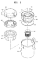
- FIG. 2 is a disassembled perspective view illustrating a multi-cyclone dust separating apparatus in accordance with the present invention.
- FIG. 3 is a partially-cut assembly perspective view illustrating the multi-cyclone dust separating apparatus in accordance with the present invention.
- FIG. 4 is a plane perspective view illustrating a grill member of FIG. 2.
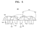
- FIG. 5 is a front view illustrating an inflow/outflow cover of FIG. 2.
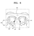
- FIG. 6 is a bottom enlarged perspective view illustrating major elements of FIG. 5.
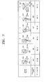
- FIG. 7 is a table showing the pressure drop and the dust collecting efficiency of the multi-cyclone dust separating apparatus of the present invention and the conventional multi-cyclone dust separating apparatuses.
- the multi-cyclone dust separating apparatus 100 includes a dust collecting housing 200, a primary cyclone 300 installed in the dust collecting housing 200, a plurality of secondary cyclones 400 installed in the dust collecting housing 200 on the outer circumference of the primary cyclone 300 at predetermined intervals, an inflow/outflow cover 500 coupled to the upper portions of the primary and secondary cyclones 300 and 400, and a cyclone cover 600 coupled to the upper portion of the inflow/outflow cover 500.
- the primary cyclone 300 primarily centrifugally separates and removes relatively large impurities of the sucked air, and the secondary cyclones 400 secondarily centrifugally separate and remove minute impurities of the air supplied from the primary cyclone 300.
- the dust collecting housing 200 collects the impurities separated from the air in the primary and secondary cyclones 300 and 400.
- the inflow/outflow cover 500 distributes the air from the primary cyclone 300 to the plurality of secondary cyclones 400 and discharges the air from the secondary cyclones 400.
- the cyclone cover 600 collects the air discharged through the inflow/outflow cover 500 and externally discharges the collected air from the multi-cyclone dust separating apparatus 100.
- the dust collecting housing 200 is formed in a cylindrical shape having its top end opened and its bottom end closed, and composes the outer appearance of the multi-cyclone dust separating apparatus 100.
- a handle 210 is installed on one side wall of the dust collecting housing 200.
- a through hole 220 is formed on the other side wall of the dust collecting housing 200, so that the outside air can be sucked into the multi-cyclone dust separating apparatus 100.
- the primary cyclone 300 includes a first chamber outer wall 320 for forming a primary cyclone chamber 310, an air outflow hole 330 for discharging the air from the primary cyclone chamber 310, and a grill member 340.
- the first chamber outer wall 320 is formed in a cylindrical shape.
- the first chamber outer wall 320 has its lower portion opened and its upper portion opened through the air outflow hole 330.
- An inflow port 372 is connected to one side of the first chamber outer wall 320 for inflow of the outside air.
- the outside air supplied through the inflow port 372 forms a rotary current in the primary cyclone chamber 310.
- the impurities in the air are concentrated on the primary chamber outer wall 320 by the centrifugal force and separated from the air.
- the air separated from the impurities in the primary cyclone 310 is discharged from the primary cyclone 300 through the air outflow hole 330.
- the air outflow hole 330 is formed smaller than the diameter of the first chamber outer wall 320.
- the grill member 340 prevents relatively large impurities centrifugally separated in the primary cyclone chamber 310 from flowing backward and being discharged through the air outflow hole 330.
- the grill member 340 is formed in a cylindrical shape having its top end opened and its bottom end closed.
- a plurality of minute holes 341a are formed on the side 341 of the grill member 340.
- grill member 340 includes an air guide member 344 protruding from the bottom 342 of the grill member 340 by a predetermined height.
- the air guide member 344 maintains upward flow of the air passing through the plurality of minute holes 341a of the side 341.
- the air guide member 344 protrudes from the bottom 342 to a predetermined height that is substantially equal to the uppermost holes 341a of the side 341.
- the air guide member 344 includes a plurality of members for uniformly dividing the inside area of the grill member 340.
- the air guide member 344 includes a first member 344a, a second member 344b, a third member 344c, and a fourth member 344d to divide the grill member 340 into four areas. That is, the air guide member 344 has a cross-shaped section. Accordingly, the air supplied from the four directions by the air guide member 344 is not mixed in the grill member 340.
- the first to fourth members 344a to 344d have their ends coupled to each other or are formed as a single body.
- the air supplied from the grill member 34 is mixed together in the grill member 34, thereby generating an eddy current.
- a pressure drop is generated within the grill member 34, which reduces the suction force.
- the air and dusts passing through the minute holes 341a are not mixed in the grill member 340 due to the air guide member 344, but rather is upwardly guided to the air outflow hole 330 without generating an eddy current.
- reduction of the suction force can be minimized.
- an isolating member 350 is coupled to the bottom end of the first chamber outer wall 320.
- the end of the isolating member 350 is connected to the inside surface of the dust collecting housing 200.
- the isolating member 350 isolates the inside of the dust collecting housing 200 in order to individually collect the impurities separated from the air in the primary cyclone 300 and the secondary cyclones 400.
- a cyclone housing 370 has cyclone insertion holes 371 outside the first chamber outer wall 320 into which the plurality of secondary cyclones 400 are inserted.
- the plurality of cyclones 400 are inserted into the cyclone insertion holes 371, and the cyclone housing 370 surrounds the predetermined portions of the upper portions of the cyclones 400.
- the inflow port 372 is installed in the cyclone housing 370 to correspond to the through hole 220 of the dust collecting housing 200.
- the inflow port 372 is extended to the first chamber outer wall 320, for supplying the outside air sucked through the through hole 220 to the primary cyclone 300.
- the secondary cyclones 400 are disposed on an outer circumference of a plate-shaped support body 401 having an opening on its center at predetermined intervals. In the case that the secondary cyclones 400 are inserted into the dust collecting housing 200, the secondary cyclones 400 are installed on the outer circumference of the first chamber outer wall 320 of the primary cyclone 300.
- Each of the plurality of secondary cyclones 400 includes a second chamber outer wall 420 composing a secondary cyclone chamber 410, and an air inflow hole 430.
- the second chamber outer walls 420 are formed in an inverse circular conical shape having their diameter downwardly reduced and their one end partially cut.
- the air containing the minute impurities that have not been filtered in the primary cyclone 300 is descended to form a rotary current in the secondary cyclone chambers 410.
- the minute impurities contained in the air are centrifugally separated and discharged to the bottom ends of the second chamber outer walls 420.
- the air whose impurities have been centrifugally separated and removed in the secondary cyclone chambers 410 is discharged through discharge guide tubes 530 of the inflow/outflow cover 500.
- the inflow/outflow cover 500 includes an inflow/outflow cover body 510, inflow guide paths 520, and discharge guide tubes 530.
- the inflow/outflow cover body 510 includes an air guide unit 511 protruded from the center in a hemispherical shape having a predetermined radius, and a plate-shaped support unit 512 disposed around the air guide unit 511.
- the diameter of the air guide unit 511 is almost identical to the diameter of the air outflow hole 330 of the primary cyclone 300. The air discharged through the air outflow hole 330 is ascended to the air guide unit 511.
- the inflow guide paths 520 are disposed in the radial direction from the air guide unit 511.
- the inflow guide paths 520 link the air outflow hole 330 of the primary cyclone 300 to the air inflow holes 430 of the secondary cyclones 400.
- the inflow guide paths 520 are extended from the outside surface of the air guide unit 511 to the support unit 512 in a downwardly-inclined spiral shape.
- the air discharged through the air outflow hole 330 is induced as small air flow in the radial direction in the air guide unit 511 by the inflow guide paths 520, and supplied to each secondary cyclone 400.
- the discharge guide tubes 530 are formed in a tube shape having a predetermined length and pass through the support unit 512 of the inflow/outflow cover body 510 in the vertical direction.
- the predetermined portions of the discharge guide tubes 530 downwardly protrude from the support unit 512 into the secondary cyclones 400. Accordingly, the air whose minute impurities have been centrifugally separated in the secondary cyclone chambers 410 of the secondary cyclones 400 ascends and discharged through the discharge guide tubes 530.
- the portions of the discharge guide tubes 530 downwardly protruding from the support unit 512 include cylindrical portions 531 having a predetermined length and intercepting portions 532 extending from the bottom ends of the cylindrical portions 531.
- the intercepting portions 532 may be circular-arc-shaped.
- Each of the intercepting portions 532 is formed by cutting a cylinder having the same diameter as the cylindrical portion 531 approximately in half. That is, the length of the circular arc of the intercepting portion 532 ranges from 1/3 to 2/3, preferably, about 1/2 of the circular circumference of the cylindrical portion 531.
- the intercepting portions 532 serve to prevent the air supplied to the secondary cyclones 400 through the inflow guide paths 520 from being directly discharged to the discharge guide tubes 530.
- the intercepting portions 532 are connected to or integrally formed with the cylindrical portions 531 under the end points 537 of the air inflow holes 430 of each secondary cyclone 400.
- the intercepting portions 532 are installed at the lower ends of the cylindrical portions 531 vertically under the end points 537 of the air inflow holes 430, and the cutting units 535 are installed at the lower ends of the cylindrical portions 531 under the opposite sides to the end points 537 of the air inflow holes 430.
- a suction motor (not shown) for generating a suction driving source is connected to a discharge port 610 of the cyclone cover 600.
- the suction force of the suction motor is transmitted through the discharge guide tubes 530.
- the air supplied to the secondary cyclones 400 through the inflow guide paths 520 must descend to the lower portions of the secondary cyclones 400, forming the rotary current, and ascend and discharge through the discharge guide tubes 530.
- the air discharged from the inflow guide paths is directly discharged to the discharge guide tubes by the suction force of the suction motor (not shown).
- the air containing the impurities is not centrifugally separated in the secondary cyclones but directly externally discharged from the multi-cyclone dust separating apparatus.
- the air supplied to the secondary cyclones 400 through the inflow guide paths 520 collides with the intercepting portions 532. Therefore, the air is not directly supplied to the discharge guide tubes 530, but descends to the secondary cyclones 400, forming the rotary current.
- the intercepting portions 532 are formed in a circular arc shape, the intercepting portions 532 can minimize the pressure drop of the air.
- FIG. 7 shows experimental data of the dust collecting efficiency and the pressure drop of the multi-cyclone dust separating apparatuses using the discharge guide tubes 530 of the present invention and the general discharge guide tubes 530 that do not have the intercepting portions 532.
- columns (i) to (v) show discharge guide tubes 530' that do not have the intercepting portions 532.
- the shape and length of the inflow guide paths 520' are identical and the length of the discharge guide tubes 530' are different.
- the discharge guide tubes 530' are formed in a cylindrical shape.
- Column (vi) shows the discharge guide tubes 530 having the intercepting portions 532 in accordance with the present invention.
- the pressure drop shown in millimeters of water illustrates the numerical values of the pressure drop of the air when the air is sucked by the same suction motor with the same power.
- the dust collecting efficiency shows the impurity filtering efficiency of the multi-cyclone dust collecting device 100 in percent (%) unit. For example, when 100g of impurities are supplied to the multi-cyclone dust collecting device 100, if the amount of the impurities that are not externally discharged but collected in the dust collecting housing 200 is 95g, the dust collecting efficiency is 95%.
- the discharge guide tubes 530' do not have the intercepting portions 532 as in columns (i) to (v), when the discharge guide tubes 530' are lengthened, the dust collecting efficiency is improved. That is, when the discharge guide tubes 530' are lengthened, less of the air supplied to the secondary cyclones 400 is supplied to the discharge guide tubes 530'. However, when the length of the discharge guide tubes 530' exceeds 15mm, the pressure drop increases. That is, when the discharge guide tubes 530' are lengthened, the air supplied to the secondary cyclones 400 collides more with the discharge guide tubes 530'.
- the length of the intercepting portions 532 is preferably about 1/3 of the length of the cylindrical portions 531, but can be 1/4 to 1/2.
- the intercepting portions 532 are shortened, more of the air is supplied to the discharge guide tubes 530, to reduce the suction efficiency, and when the intercepting portions 532 are lengthened, the air supplied to the secondary cyclones 400 collides more with the intercepting portions 532, to increase the pressure drop.
- the length of the cylindrical portions 531 was set to be 15mm showing the minimum pressure drop among column (i) to (v), and the length of the intercepting portions 532 was set to be 5mm, namely, 1/3 of the length of the cylindrical portions 531.
- the cyclone cover 600 is coupled to cover the inflow/outflow cover 500, and includes the discharge port 610 for collecting the air from the plurality of discharge guide tubes 530 and externally discharging the air from the multi-cyclone dust separating apparatus 100.
- the suction motor (not shown) of the vacuum cleaner for proving the suction force is directly or indirectly connected to the discharge port 610.
- the air containing the impurities is supplied to the primary cyclone 100 through the inflow port 372 (refer to FIG. 2).
- the air is descended in the primary cyclone chamber 310, forming the rotary current.
- the relatively large impurities of the air are centrifugally separated, descended and collected in the dust collecting housing 200.
- the air whose large impurities have been removed is ascended again, passed through the side 341 of the grill member 340, guided by the air guide member 344, and discharged through the air outflow hole 330.
- the air ascended through the air outflow hole 330 is diffused by collision with the air guide unit 511, and supplied to each secondary cyclone 400 through the inflow guide paths 520.
- the air discharged through the air inflow holes 430 is not directly supplied to the discharge guide tubes 530 by the intercepting portions 532 of the discharge guide tubes 530 but guided to the lower portions of the secondary cyclone chambers 410.
- the air is descended, forming the rotary current.
- the minute impurities of the air that have not been separated in the primary cyclone 300 are centrifugally separated, descended and collected in the dust collecting housing 200.
- the air whose minute dusts have been removed is ascended and discharged through the discharge guide tubes 530.
- the air discharged from each discharge guide tube 530 is mixed in the cyclone cover 600, and externally discharged from the multi-cyclone dust separating apparatus 100 through the discharge port 610.
- the multi-cyclone dust separating apparatus 100 in accordance with the present invention can be selectively applied to various types of cleaners, such as upright type or canister type vacuum cleaners.
- the multi-cyclone having the primary cyclone and the plurality of secondary cyclones has been explained in the above embodiment.
- the present invention can be applied to any kinds of cyclone dust separating apparatuses including the discharge guide tubes 530 having the intercepting portions 532 and the cylindrical portions 531 (refer to FIG. 5).
- the present invention can be applied to the cyclone dust separating apparatus having one cyclone including an air inflow hole (not shown) for forming a rotary current like the inflow guide paths, a cyclone body (not shown) for providing an airtight space for separating impurities by rotating the sucked air, and a discharge guide tube 530 having cylindrical portions and intercepting portions, and guiding the air from the cyclone body.
- the intercepting portions are formed at the bottom ends of the cylindrical portions, the sucked air is not directly discharged to the discharge guide tubes.
- the air supplied to the secondary cyclones is not directly discharged to the discharge guide tubes, by installing the predetermined length of intercepting portions of the discharge guide tubes for discharge the air of the secondary cyclones at the lower portions of the ends of the air inflow holes of the secondary cyclones.
- the dust collecting efficiency is improved, and the air pressure drop is reduced by restricting collision of the sucked air and the discharged air.
- the air guide member for guiding ascent of the air is installed in the grill member, the air flow is constantly maintained in the grill member by restricting generation of the eddy current, thereby preventing the pressure drop.
Abstract
Description
- This application claims benefit under 35 U.S.C. § 119(a) of
Korean Patent Application No. 2005-50917, filed June 14, 2005 - The present invention relates to a vacuum cleaner, and more particularly, to a multi-cyclone dust separating apparatus that can centrifugally separate impurities from the sucked air.
- In general, a vacuum cleaner includes a suction brush for sucking the air containing impurities from the bottom, a dust separating apparatus for separating the impurities from the air sucked through the suction brush, and a suction motor that generates a suction driving source. The dust separating apparatus normally uses a dust bag. The dust bag is frequently replaced and unsanitary. Accordingly, a multi-cyclone dust separating apparatus that can be semipermanently used without a dust bag has been recently widely used.
- The cyclone dust separating apparatus is a dust separating apparatus that centrifugally separates impurities from the air by rotating the air containing the impurities. The cyclone dust separating apparatus includes a cyclone body (not shown), an air inflow hole formed on the side of the cyclone body, and a discharge guide tube (not shown) installed at the upper portion thereof. However, the air supplied to the cyclone body rotates and collides with the discharge air discharged through the discharge guide tube, thereby causing a pressure drop and a reduction in the suction force. Particularly, a multi-cyclone dust separating apparatus having a plurality of cyclones to improve the dust collecting efficiency has such problems in the secondary or tertiary cyclones composed of a plurality of small cyclones.
- A multi-cyclone dust separating apparatus (having a primary cyclone and a plurality of secondary cyclones) filed by the present applicant (
Korean Publication No. 10-2005-0025711 dust separating apparatus 10 includes aprimary cyclone 30 for primarily centrifugally separating impurities from the sucked air,secondary cyclones 40 for secondarily centrifugally separating impurities from the air supplied from theprimary cyclone 30, adust collecting vessel 20 for collecting the impurities separated from the air in the primary andsecondary cyclones outflow cover 50 for guiding the air discharged from theprimary cyclone 30 to thesecondary cyclones 40, and acyclone cover 60 for externally discharging the air from the inflow/outflow cover 50 to the outer space of the dust separating apparatus. - The plurality of
secondary cyclones 40 are disposed on the outer circumference of theprimary cyclone 30 at predetermined intervals, for centrifugally separating minute dusts that have not been separated from the air in theprimary cyclone 30. On the other hand, agrill member 34 is installed in theprimary cyclone 30, for preventing the impurities from flowing backward and being discharged through anair outflow hole 33 of theprimary cyclone 30. The inflow/outflow cover 50 includesinflow guide tubes 52 for guiding the air discharged from theprimary cyclone 30 to thesecondary cyclones 40, anddischarge guide tubes 53 for externally discharging the air of thesecondary cyclones 40. The predetermined portions of thedischarge guide tubes 53 are inserted into thesecondary cyclones 40. A suction motor (not shown) of a vacuum cleaner is directly or indirectly connected to adischarge port 61 of thecyclone cover 60. - The operation of the multi-cyclone
dust separating apparatus 10 will now be described. When power is applied to the vacuum cleaner and the suction motor (not shown) is driven, the outside air is supplied to theprimary cyclone 30 through the suction port 37, and the impurities in the outside air are primarily centrifugally separated and collected in thedust collecting vessel 20. The air separated from the impurities passes through thegrill member 34, is distributed along theinflow guide tubes 52 of the inflow/outflow cover 50, and supplied to the plurality ofsecondary cyclones 20. The impurities of the air are secondarily centrifugally separated and collected in thedust collecting vessel 20. The air separated from the impurities is ascended, collected in thecyclone cover 60 through thedischarge guide tubes 53, and externally discharged from the multi-cyclonedust separating apparatus 10 through thedischarge port 61. - The multi-cyclone
dust separating apparatus 10 has high dust collecting efficiency because the plurality ofsecondary cyclones 40 are disposed on the outer circumference of theprimary cyclone 30, for sequentially centrifugally separating the impurities of the air. - However, the multi-cyclone
dust separating apparatus 10 has the following problems. - First, when the air discharged from the
primary cyclone 30 is supplied to thesecondary cyclones 40 through theinflow guide tubes 52, as indicated by arrows A, most of the air is not supplied to the lower portions of thesecondary cyclones 40 but directly discharged to thedischarge guide tubes 53 by the suction force of thedischarge guide tubes 53. Therefore, the minute impurities that have not been filtered in theprimary cyclone 30 are externally discharged through thecyclone cover 60 with the air, thereby reducing the dust collecting efficiency of the multi-cyclonedust separating apparatus 10. - In order to solve the foregoing problem, the
discharge guide tubes 53 can be inserted deeper into thesecondary cyclones 40. However, the air supplied to thesecondary cyclones 40 seriously collides with thedischarge guide tubes 53 to cause the pressure drop and reduce the suction force. If the suction force decreases, thesecondary cyclones 40 cannot form a proper rotary current, thereby reducing the dust collecting efficiency. - Second, the air centrifugally separated from the impurities in the
primary cyclone 30 is ascended through thegrill member 34 and supplied to thesecondary cyclones 40 through theair outflow hole 33. Here, the air supplied from the four directions is mixed and eddied inside thegrill member 34, to generate an eddy current. As a result, the pressure drop is generated in the air, and the suction force of the suction motor is reduced due to the air pressure drop. - Accordingly, it is an object of the present invention to provide a multi-cyclone dust separating apparatus that can maintain an appropriate suction force and prevent pressure drop, by restricting mixing of the air supplied to cyclones and the air discharged through discharge guide tubes.
- Another object of the present invention is to provide a multi-cyclone dust separating apparatus that can prevent pressure drop by collision of the air passing through a grill member for filtering off dusts from different directions.
- In order to achieve the above objects of the invention, there is provided a cyclone dust separating apparatus, including: a cyclone body having an air inflow hole through that the outside air containing impurities is sucked; and a discharge guide tube for discharging the air from the cyclone body, the discharge guide tube including a cylindrical portion, and an intercepting portion extended from the bottom end of the cylindrical portion for preventing the air supplied to the cyclone body from being directly discharged to the discharge guide tube. Therefore, the cyclone dust separating apparatus can maintain an appropriate suction force, restricting mixing of the air supplied to the cyclone body and the discharged air.
- Preferably, the intercepting portion is installed at the lower end of the cylindrical portion vertically under the end point of the air inflow hole of the cyclone body, and is circular-arc-shaped.
- According to one aspect of the invention, there is provided a multi-cyclone dust separating apparatus, including: a primary cyclone for centrifugally separating impurities from the sucked air; a plurality of secondary cyclones for centrifugally separating impurities from the air supplied from the primary cyclone; inflow guide paths for guiding the air discharged from the primary cyclone to the plurality of secondary cyclones; and discharge guide tubes partially inserted into the secondary cyclones, for externally discharging the air of the secondary cyclones. The discharge guide tubes include cylindrical portions, and intercepting portions extended from the bottom ends of the cylindrical portions, for preventing the air supplied to the secondary cyclones from being directly discharged to the discharge guide tubes.
- Preferably, the multi-cyclone dust separating apparatus further includes an inflow/outflow cover installed on the top ends of the secondary cyclones, wherein the plurality of secondary cyclones are disposed at an outer circumference of the primary cyclone at predetermined intervals, and the inflow guide paths and the discharge guide tubes are integrally formed on the inflow/outflow cover.
- Preferably, the intercepting portions are installed at the lower ends of the cylindrical portions vertically under the end points of the air inflow holes of the secondary cyclones, and are circular-arc-shaped.
- Preferably, the length of the circular arc of the intercepting portion ranges from 1/3 to 2/3 of the circular circumference of the cylindrical portion, and more preferably, the length of the intercepting portion ranges from 1/4 to 1/2 of the length of the cylindrical portion.
- Preferably, in the multi-cyclone dust separating apparatus, the primary cyclone includes a cylindrical grill member installed on an air outflow hole through which the air is discharged, for preventing backflow of impurities. The grill member includes an air guide member protruded from the bottom in the height direction, for guiding the air passing through the grill member to the air outflow hole.
- Preferably, the air guide member divides the inside area of the grill member into a plurality of uniform areas. More preferably, the air guide member has a cross-shaped section to divide the inside area of the grill member into four areas.
- The above aspects and features of the present invention will be more apparent by describing certain embodiments of the present invention with reference to the accompanying drawings, in which:
- FIG. 1 is a cross-sectional view illustrating a conventional multi-cyclone dust separating apparatus.
- FIG. 2 is a disassembled perspective view illustrating a multi-cyclone dust separating apparatus in accordance with the present invention.
- FIG. 3 is a partially-cut assembly perspective view illustrating the multi-cyclone dust separating apparatus in accordance with the present invention.
- FIG. 4 is a plane perspective view illustrating a grill member of FIG. 2.
- FIG. 5 is a front view illustrating an inflow/outflow cover of FIG. 2.
- FIG. 6 is a bottom enlarged perspective view illustrating major elements of FIG. 5.
- FIG. 7 is a table showing the pressure drop and the dust collecting efficiency of the multi-cyclone dust separating apparatus of the present invention and the conventional multi-cyclone dust separating apparatuses.
- A multi-cyclone dust separating apparatus in accordance with the present invention will now be described in detail with reference to the accompanying drawings.
- As illustrated in FIG. 2, the multi-cyclone
dust separating apparatus 100 includes adust collecting housing 200, aprimary cyclone 300 installed in thedust collecting housing 200, a plurality ofsecondary cyclones 400 installed in thedust collecting housing 200 on the outer circumference of theprimary cyclone 300 at predetermined intervals, an inflow/outflow cover 500 coupled to the upper portions of the primary andsecondary cyclones cyclone cover 600 coupled to the upper portion of the inflow/outflow cover 500. - The
primary cyclone 300 primarily centrifugally separates and removes relatively large impurities of the sucked air, and thesecondary cyclones 400 secondarily centrifugally separate and remove minute impurities of the air supplied from theprimary cyclone 300. Thedust collecting housing 200 collects the impurities separated from the air in the primary andsecondary cyclones outflow cover 500 distributes the air from theprimary cyclone 300 to the plurality ofsecondary cyclones 400 and discharges the air from thesecondary cyclones 400. Thecyclone cover 600 collects the air discharged through the inflow/outflow cover 500 and externally discharges the collected air from the multi-cyclonedust separating apparatus 100. - The
dust collecting housing 200 is formed in a cylindrical shape having its top end opened and its bottom end closed, and composes the outer appearance of the multi-cyclonedust separating apparatus 100. Ahandle 210 is installed on one side wall of thedust collecting housing 200. On the other hand, a throughhole 220 is formed on the other side wall of thedust collecting housing 200, so that the outside air can be sucked into the multi-cyclonedust separating apparatus 100. - As shown in FIGS. 2 and 3, the
primary cyclone 300 includes a first chamberouter wall 320 for forming aprimary cyclone chamber 310, anair outflow hole 330 for discharging the air from theprimary cyclone chamber 310, and agrill member 340. - Identically to the
dust collecting housing 200, the first chamberouter wall 320 is formed in a cylindrical shape. The first chamberouter wall 320 has its lower portion opened and its upper portion opened through theair outflow hole 330. Aninflow port 372 is connected to one side of the first chamberouter wall 320 for inflow of the outside air. The outside air supplied through theinflow port 372 forms a rotary current in theprimary cyclone chamber 310. The impurities in the air are concentrated on the primary chamberouter wall 320 by the centrifugal force and separated from the air. The air separated from the impurities in theprimary cyclone 310 is discharged from theprimary cyclone 300 through theair outflow hole 330. Theair outflow hole 330 is formed smaller than the diameter of the first chamberouter wall 320. - As depicted in FIGS. 3 and 4, the
grill member 340 prevents relatively large impurities centrifugally separated in theprimary cyclone chamber 310 from flowing backward and being discharged through theair outflow hole 330. Thegrill member 340 is formed in a cylindrical shape having its top end opened and its bottom end closed. In addition, a plurality ofminute holes 341a are formed on theside 341 of thegrill member 340. - In addition,
grill member 340 includes anair guide member 344 protruding from thebottom 342 of thegrill member 340 by a predetermined height. Theair guide member 344 maintains upward flow of the air passing through the plurality ofminute holes 341a of theside 341. Preferably, theair guide member 344 protrudes from the bottom 342 to a predetermined height that is substantially equal to theuppermost holes 341a of theside 341. - Preferably, the
air guide member 344 includes a plurality of members for uniformly dividing the inside area of thegrill member 340. In this manner, the air containing the minute dusts enters theside 341 of thegrill member 340 from four directions as indicated by arrows B, C, D and E. Therefore, still referring to FIG. 4, theair guide member 344 includes a first member 344a, a second member 344b, athird member 344c, and a fourth member 344d to divide thegrill member 340 into four areas. That is, theair guide member 344 has a cross-shaped section. Accordingly, the air supplied from the four directions by theair guide member 344 is not mixed in thegrill member 340. The first to fourth members 344a to 344d have their ends coupled to each other or are formed as a single body. - As described above, in the conventional multi-cyclone dust separating apparatus using the grill member 34 (refer to FIG. 1), the air supplied from the
grill member 34 is mixed together in thegrill member 34, thereby generating an eddy current. As a result, a pressure drop is generated within thegrill member 34, which reduces the suction force. However, in accordance with the present invention, the air and dusts passing through theminute holes 341a are not mixed in thegrill member 340 due to theair guide member 344, but rather is upwardly guided to theair outflow hole 330 without generating an eddy current. Thus, reduction of the suction force can be minimized. - Still referring to FIGS. 2 and 3, an isolating
member 350 is coupled to the bottom end of the first chamberouter wall 320. The end of the isolatingmember 350 is connected to the inside surface of thedust collecting housing 200. The isolatingmember 350 isolates the inside of thedust collecting housing 200 in order to individually collect the impurities separated from the air in theprimary cyclone 300 and thesecondary cyclones 400. - On the other hand, a
cyclone housing 370 has cyclone insertion holes 371 outside the first chamberouter wall 320 into which the plurality ofsecondary cyclones 400 are inserted. When theprimary cyclone 300 and thesecondary cyclones 400 are coupled in thedust collecting housing 200, the plurality ofcyclones 400 are inserted into the cyclone insertion holes 371, and thecyclone housing 370 surrounds the predetermined portions of the upper portions of thecyclones 400. Theinflow port 372 is installed in thecyclone housing 370 to correspond to the throughhole 220 of thedust collecting housing 200. Theinflow port 372 is extended to the first chamberouter wall 320, for supplying the outside air sucked through the throughhole 220 to theprimary cyclone 300. - The
secondary cyclones 400 are disposed on an outer circumference of a plate-shapedsupport body 401 having an opening on its center at predetermined intervals. In the case that thesecondary cyclones 400 are inserted into thedust collecting housing 200, thesecondary cyclones 400 are installed on the outer circumference of the first chamberouter wall 320 of theprimary cyclone 300. - Each of the plurality of
secondary cyclones 400 includes a second chamberouter wall 420 composing asecondary cyclone chamber 410, and anair inflow hole 430. The second chamberouter walls 420 are formed in an inverse circular conical shape having their diameter downwardly reduced and their one end partially cut. The air containing the minute impurities that have not been filtered in theprimary cyclone 300 is descended to form a rotary current in thesecondary cyclone chambers 410. The minute impurities contained in the air are centrifugally separated and discharged to the bottom ends of the second chamberouter walls 420. The air whose impurities have been centrifugally separated and removed in thesecondary cyclone chambers 410 is discharged throughdischarge guide tubes 530 of the inflow/outflow cover 500. - As illustrated in FIGS. 2, 5 and 6, the inflow/
outflow cover 500 includes an inflow/outflow cover body 510,inflow guide paths 520, and dischargeguide tubes 530. - The inflow/
outflow cover body 510 includes anair guide unit 511 protruded from the center in a hemispherical shape having a predetermined radius, and a plate-shapedsupport unit 512 disposed around theair guide unit 511. The diameter of theair guide unit 511 is almost identical to the diameter of theair outflow hole 330 of theprimary cyclone 300. The air discharged through theair outflow hole 330 is ascended to theair guide unit 511. - The
inflow guide paths 520 are disposed in the radial direction from theair guide unit 511. Theinflow guide paths 520 link theair outflow hole 330 of theprimary cyclone 300 to the air inflow holes 430 of thesecondary cyclones 400. Also, theinflow guide paths 520 are extended from the outside surface of theair guide unit 511 to thesupport unit 512 in a downwardly-inclined spiral shape. The air discharged through theair outflow hole 330 is induced as small air flow in the radial direction in theair guide unit 511 by theinflow guide paths 520, and supplied to eachsecondary cyclone 400. - The
discharge guide tubes 530 are formed in a tube shape having a predetermined length and pass through thesupport unit 512 of the inflow/outflow cover body 510 in the vertical direction. When the inflow/outflow cover 500 is coupled to the upper portions of thesecondary cyclones 400, the predetermined portions of thedischarge guide tubes 530 downwardly protrude from thesupport unit 512 into thesecondary cyclones 400. Accordingly, the air whose minute impurities have been centrifugally separated in thesecondary cyclone chambers 410 of thesecondary cyclones 400 ascends and discharged through thedischarge guide tubes 530. - As shown in FIG. 5, the portions of the
discharge guide tubes 530 downwardly protruding from thesupport unit 512 includecylindrical portions 531 having a predetermined length and interceptingportions 532 extending from the bottom ends of thecylindrical portions 531. - Preferably, the intercepting
portions 532 may be circular-arc-shaped. Each of the interceptingportions 532 is formed by cutting a cylinder having the same diameter as thecylindrical portion 531 approximately in half. That is, the length of the circular arc of the interceptingportion 532 ranges from 1/3 to 2/3, preferably, about 1/2 of the circular circumference of thecylindrical portion 531. The interceptingportions 532 serve to prevent the air supplied to thesecondary cyclones 400 through theinflow guide paths 520 from being directly discharged to thedischarge guide tubes 530. As illustrated in FIG. 6, the interceptingportions 532 are connected to or integrally formed with thecylindrical portions 531 under theend points 537 of the air inflow holes 430 of eachsecondary cyclone 400. That is, the interceptingportions 532 are installed at the lower ends of thecylindrical portions 531 vertically under theend points 537 of the air inflow holes 430, and the cuttingunits 535 are installed at the lower ends of thecylindrical portions 531 under the opposite sides to theend points 537 of the air inflow holes 430. - In general, a suction motor (not shown) for generating a suction driving source is connected to a
discharge port 610 of thecyclone cover 600. The suction force of the suction motor is transmitted through thedischarge guide tubes 530. On the other hand, the air supplied to thesecondary cyclones 400 through theinflow guide paths 520 must descend to the lower portions of thesecondary cyclones 400, forming the rotary current, and ascend and discharge through thedischarge guide tubes 530. However, in the conventional art, the air discharged from the inflow guide paths is directly discharged to the discharge guide tubes by the suction force of the suction motor (not shown). Thus in the conventional art, the air containing the impurities is not centrifugally separated in the secondary cyclones but directly externally discharged from the multi-cyclone dust separating apparatus. - In accordance with the present invention, as indicated by arrows F and G of FIG. 6, the air supplied to the
secondary cyclones 400 through theinflow guide paths 520 collides with the interceptingportions 532. Therefore, the air is not directly supplied to thedischarge guide tubes 530, but descends to thesecondary cyclones 400, forming the rotary current. On the other hand, since the interceptingportions 532 are formed in a circular arc shape, the interceptingportions 532 can minimize the pressure drop of the air. - FIG. 7 shows experimental data of the dust collecting efficiency and the pressure drop of the multi-cyclone dust separating apparatuses using the
discharge guide tubes 530 of the present invention and the generaldischarge guide tubes 530 that do not have the interceptingportions 532. - Referring to FIG. 7, columns (i) to (v) show discharge guide tubes 530' that do not have the intercepting
portions 532. Here, the shape and length of the inflow guide paths 520' are identical and the length of the discharge guide tubes 530' are different. The discharge guide tubes 530' are formed in a cylindrical shape. Column (vi) shows thedischarge guide tubes 530 having the interceptingportions 532 in accordance with the present invention. The pressure drop shown in millimeters of water illustrates the numerical values of the pressure drop of the air when the air is sucked by the same suction motor with the same power. The dust collecting efficiency shows the impurity filtering efficiency of the multi-cyclonedust collecting device 100 in percent (%) unit. For example, when 100g of impurities are supplied to the multi-cyclonedust collecting device 100, if the amount of the impurities that are not externally discharged but collected in thedust collecting housing 200 is 95g, the dust collecting efficiency is 95%. - In the case that the discharge guide tubes 530' do not have the intercepting
portions 532 as in columns (i) to (v), when the discharge guide tubes 530' are lengthened, the dust collecting efficiency is improved. That is, when the discharge guide tubes 530' are lengthened, less of the air supplied to thesecondary cyclones 400 is supplied to the discharge guide tubes 530'. However, when the length of the discharge guide tubes 530' exceeds 15mm, the pressure drop increases. That is, when the discharge guide tubes 530' are lengthened, the air supplied to thesecondary cyclones 400 collides more with the discharge guide tubes 530'. - Conversely, when the discharge guide tubes 530' have the intercepting
portions 532 as in column (vi), the dust collecting efficiency is improved and the pressure drop is remarkably reduced. On the other hand, the length of the interceptingportions 532 is preferably about 1/3 of the length of thecylindrical portions 531, but can be 1/4 to 1/2. When the interceptingportions 532 are shortened, more of the air is supplied to thedischarge guide tubes 530, to reduce the suction efficiency, and when the interceptingportions 532 are lengthened, the air supplied to thesecondary cyclones 400 collides more with the interceptingportions 532, to increase the pressure drop. In this experiment, the length of thecylindrical portions 531 was set to be 15mm showing the minimum pressure drop among column (i) to (v), and the length of the interceptingportions 532 was set to be 5mm, namely, 1/3 of the length of thecylindrical portions 531. - Referring back to FIG. 2, the
cyclone cover 600 is coupled to cover the inflow/outflow cover 500, and includes thedischarge port 610 for collecting the air from the plurality ofdischarge guide tubes 530 and externally discharging the air from the multi-cyclonedust separating apparatus 100. The suction motor (not shown) of the vacuum cleaner for proving the suction force is directly or indirectly connected to thedischarge port 610. - The operation of the multi-cyclone
dust separating apparatus 100 in accordance with the present invention will now be described with reference to FIG. 3. - When the suction motor (not shown) of the vacuum cleaner is driven, the air containing the impurities is supplied to the
primary cyclone 100 through the inflow port 372 (refer to FIG. 2). The air is descended in theprimary cyclone chamber 310, forming the rotary current. The relatively large impurities of the air are centrifugally separated, descended and collected in thedust collecting housing 200. The air whose large impurities have been removed is ascended again, passed through theside 341 of thegrill member 340, guided by theair guide member 344, and discharged through theair outflow hole 330. - The air ascended through the
air outflow hole 330 is diffused by collision with theair guide unit 511, and supplied to eachsecondary cyclone 400 through theinflow guide paths 520. Here, the air discharged through the air inflow holes 430 is not directly supplied to thedischarge guide tubes 530 by the interceptingportions 532 of thedischarge guide tubes 530 but guided to the lower portions of thesecondary cyclone chambers 410. The air is descended, forming the rotary current. The minute impurities of the air that have not been separated in theprimary cyclone 300 are centrifugally separated, descended and collected in thedust collecting housing 200. - The air whose minute dusts have been removed is ascended and discharged through the
discharge guide tubes 530. The air discharged from eachdischarge guide tube 530 is mixed in thecyclone cover 600, and externally discharged from the multi-cyclonedust separating apparatus 100 through thedischarge port 610. - Although not illustrated, the multi-cyclone
dust separating apparatus 100 in accordance with the present invention can be selectively applied to various types of cleaners, such as upright type or canister type vacuum cleaners. - The multi-cyclone having the primary cyclone and the plurality of secondary cyclones has been explained in the above embodiment. However, the present invention can be applied to any kinds of cyclone dust separating apparatuses including the
discharge guide tubes 530 having the interceptingportions 532 and the cylindrical portions 531 (refer to FIG. 5). That is, it is easily understood by those skilled in the art that the present invention can be applied to the cyclone dust separating apparatus having one cyclone including an air inflow hole (not shown) for forming a rotary current like the inflow guide paths, a cyclone body (not shown) for providing an airtight space for separating impurities by rotating the sucked air, and adischarge guide tube 530 having cylindrical portions and intercepting portions, and guiding the air from the cyclone body. - As discussed earlier, in accordance with the present invention, in the multi-cyclone dust separating apparatus, since the intercepting portions are formed at the bottom ends of the cylindrical portions, the sucked air is not directly discharged to the discharge guide tubes.
- In addition, in the multi-cyclone of the above embodiment, the air supplied to the secondary cyclones is not directly discharged to the discharge guide tubes, by installing the predetermined length of intercepting portions of the discharge guide tubes for discharge the air of the secondary cyclones at the lower portions of the ends of the air inflow holes of the secondary cyclones. As a result, the dust collecting efficiency is improved, and the air pressure drop is reduced by restricting collision of the sucked air and the discharged air.
- Furthermore, since the air guide member for guiding ascent of the air is installed in the grill member, the air flow is constantly maintained in the grill member by restricting generation of the eddy current, thereby preventing the pressure drop.
- The foregoing embodiment and advantages are merely exemplary and are not to be construed as limiting the present invention. The present teaching can be readily applied to other types of apparatuses. Also, the description of the embodiments of the present invention is intended to be illustrative, and not to limit the scope of the claims, and many alternatives, modifications, and variations will be apparent to those skilled in the art.
Claims (12)
- A multi-cyclone dust separating apparatus, comprising:a primary cyclone for centrifugally separating impurities from the sucked air;a plurality of secondary cyclones for centrifugally separating impurities from the air supplied from the primary cyclone;inflow guide paths for guiding the air discharged from the primary cyclone to the plurality of secondary cyclones; anddischarge guide tubes partially inserted into the plurality of secondary cyclones, for externally discharging the air from the plurality of secondary cyclones,wherein the discharge guide tubes comprise cylindrical portions and intercepting portions extending from bottom ends of the cylindrical portions for preventing the air supplied to the plurality of secondary cyclones from being directly discharged to the discharge guide tubes.
- The multi-cyclone dust separating apparatus as claimed in claim 1, further comprising an inflow/outflow cover installed on the top ends of the secondary cyclones,
wherein the plurality of secondary cyclones are disposed at an outer circumference of the primary cyclone at predetermined intervals, and the inflow guide paths and the discharge guide tubes are integrally formed on the inflow/outflow cover. - The multi-cyclone dust separating apparatus as claimed in any of claims 1 and 2, wherein the intercepting portions are installed at the bottom ends of the cylindrical portions vertically under end points of air inflow holes of the plurality of secondary cyclones.
- The multi-cyclone dust separating apparatus as claimed in any of claims 1 to 3, wherein the intercepting portions are circular-arc-shaped.
- The multi-cyclone dust separating apparatus as claimed in any of claims 3 and 4, wherein the length of the circular arc of the intercepting portion substantially ranges from 1/3 to 2/3 of the circular circumference of the plurality of cylindrical portions.
- The multi-cyclone dust separating apparatus as claimed in any of claims 3 to 5, wherein the height of the intercepting portion substantially ranges from 1/4 to 1/2 of the height of the plurality of cylindrical portions.
- The multi-cyclone dust separating apparatus as claimed in any of claims 1 to 6, wherein the primary cyclone comprises a cylindrical grill member installed on an air outflow hole through which the air is discharged, the cylindrical grill member preventing backflow of impurities, and wherein the grill member comprises an air guide member protruded from the bottom of the grill member, the air guide member guiding the air passing through the grill member to the air outflow hole.
- The multi-cyclone dust separating apparatus as claimed in claim 7, wherein the air guide member divides an inside area of the grill member into a plurality of areas.
- The multi-cyclone dust separating apparatus as claimed in any of claims 7 and 8, wherein the air guide member has a cross-shaped section to divide the inside area of the grill member into four areas.
- A cyclone dust separating apparatus, comprising:a cyclone body having an air inflow hole through which outside air containing impurities is sucked; anda discharge guide tube for discharging the air from the cyclone body, the discharge guide tube including a cylindrical portion and an intercepting portion, the intercepting portion extended from a bottom end of the cylindrical portion for preventing the air supplied to the cyclone body from being directly discharged to the discharge guide tube.
- The cyclone dust separating apparatus as claimed in claim 10, wherein the intercepting portion is installed at the bottom end of the cylindrical portion vertically under an end point of the air inflow hole of the cyclone body.
- The cyclone dust separating apparatus as claimed in any of claims 10 and 11,
wherein the intercepting portion is circular-arc-shaped.
Applications Claiming Priority (1)
| Application Number | Priority Date | Filing Date | Title |
|---|---|---|---|
| KR1020050050917A KR100647197B1 (en) | 2005-06-14 | 2005-06-14 | Multi cyclone dust collecting apparatus |
Publications (3)
| Publication Number | Publication Date |
|---|---|
| EP1733672A2 true EP1733672A2 (en) | 2006-12-20 |
| EP1733672A3 EP1733672A3 (en) | 2007-09-05 |
| EP1733672B1 EP1733672B1 (en) | 2013-05-22 |
Family
ID=36215544
Family Applications (1)
| Application Number | Title | Priority Date | Filing Date |
|---|---|---|---|
| EP06290378.6A Expired - Fee Related EP1733672B1 (en) | 2005-06-14 | 2006-03-07 | Multi-cyclone dust separating apparatus |
Country Status (7)
| Country | Link |
|---|---|
| US (1) | US7563297B2 (en) |
| EP (1) | EP1733672B1 (en) |
| JP (1) | JP2006346669A (en) |
| KR (1) | KR100647197B1 (en) |
| CN (1) | CN1879541A (en) |
| AU (1) | AU2006200986B2 (en) |
| RU (1) | RU2316993C2 (en) |
Cited By (5)
| Publication number | Priority date | Publication date | Assignee | Title |
|---|---|---|---|---|
| EP2119387A1 (en) | 2008-04-24 | 2009-11-18 | Suzhou Clean Bloom Electric Co. Ltd | Cyclonic dust collecting apparatus and vacuum cleaner |
| US7749292B2 (en) | 2006-11-16 | 2010-07-06 | Suzhou Clean Bloom Electric Co., Ltd. | Cyclonic dust collecting apparatus |
| US7892305B2 (en) | 2005-08-17 | 2011-02-22 | Lg Electronics Inc. | Dust collecting device for vacuum cleaner |
| EP3443879A4 (en) * | 2016-04-14 | 2019-11-20 | LG Electronics Inc. -1- | Dust collecting apparatus and vacuum cleaner having same |
| EP3443881A4 (en) * | 2016-04-14 | 2019-11-20 | LG Electronics Inc. -1- | Collecting apparatus and vacuum cleaner having same |
Families Citing this family (42)
| Publication number | Priority date | Publication date | Assignee | Title |
|---|---|---|---|---|
| KR100647197B1 (en) | 2005-06-14 | 2006-11-23 | 삼성광주전자 주식회사 | Multi cyclone dust collecting apparatus |
| GB2440125A (en) * | 2006-07-18 | 2008-01-23 | Dyson Technology Ltd | Cyclonic separating apparatus |
| GB2478155B (en) | 2010-02-26 | 2014-05-14 | Dyson Technology Ltd | A vortex finder plate for a cyclonic separating apparatus |
| US20120047682A1 (en) * | 2010-09-01 | 2012-03-01 | Makarov Sergey V | Vacuum cleaner with exhaust tube having an increasing cross-sectional area |
| CN102551607B (en) * | 2010-12-16 | 2014-01-22 | 莱克电气股份有限公司 | Dust removal device of dust collector |
| JP2013236671A (en) * | 2012-05-11 | 2013-11-28 | Toshiba Corp | Electric vacuum cleaner |
| JP5367886B1 (en) * | 2012-08-07 | 2013-12-11 | 株式会社東芝 | Dust collector and vacuum cleaner |
| JP5362889B1 (en) * | 2012-08-08 | 2013-12-11 | 株式会社東芝 | Dust collector and vacuum cleaner |
| JP5368645B1 (en) * | 2013-02-07 | 2013-12-18 | 株式会社東芝 | Dust collector and vacuum cleaner |
| US10631697B2 (en) | 2014-02-14 | 2020-04-28 | Techtronic Industries Co. Ltd. | Separator configuration |
| WO2016065146A1 (en) | 2014-10-22 | 2016-04-28 | Techtronic Industries Co. Ltd. | Vacuum cleaner having cyclonic separator |
| CN110123203A (en) | 2014-10-22 | 2019-08-16 | 创科实业有限公司 | Vacuum cleaner with cyclone separator |
| WO2016065151A1 (en) | 2014-10-22 | 2016-04-28 | Techtronic Industries Co. Ltd. | Handheld vacuum cleaner |
| EP3508275B1 (en) | 2015-01-26 | 2023-04-26 | Hayward Industries, Inc. | Swimming pool cleaner with hydrocyclonic particle separator and roller drive system |
| US9885196B2 (en) | 2015-01-26 | 2018-02-06 | Hayward Industries, Inc. | Pool cleaner power coupling |
| KR101709465B1 (en) * | 2015-03-09 | 2017-02-23 | (주)신영프레시젼 | Cyclone for removing dust |
| JP6461737B2 (en) * | 2015-07-17 | 2019-01-30 | シャープ株式会社 | Electric vacuum cleaner |
| KR102409218B1 (en) * | 2015-10-21 | 2022-06-16 | 삼성전자주식회사 | Cyclone dust collector and vacuum cleaner having the same |
| CN105662274B (en) * | 2016-01-20 | 2019-04-26 | 江苏美的清洁电器股份有限公司 | Hand held cleaner |
| CA2971070A1 (en) | 2016-01-20 | 2017-07-20 | Jiangsu Midea Cleaning Appliances Co., Ltd. | Hand-held vacuum cleaner |
| KR102290894B1 (en) * | 2016-04-14 | 2021-08-19 | 엘지전자 주식회사 | Dust collector and vacuum cleaner having the same |
| US10201260B2 (en) | 2016-04-25 | 2019-02-12 | Omachron Intellectual Property Inc. | Cyclone assembly for surface cleaning apparatus and a surface cleaning apparatus having same |
| US10537219B2 (en) | 2016-04-25 | 2020-01-21 | Omachron Intellectual Property Inc. | Cyclone assembly for surface cleaning apparatus and a surface cleaning apparatus having same |
| US9936846B2 (en) * | 2016-04-25 | 2018-04-10 | Omachron Intellectual Property Inc. | Cyclone assembly for surface cleaning apparatus and a surface cleaning apparatus having same |
| US10251521B2 (en) | 2016-04-25 | 2019-04-09 | Omachron Intellectual Property Inc. | Cyclone assembly for surface cleaning apparatus and a surface cleaning apparatus having same |
| US10149587B2 (en) | 2016-04-25 | 2018-12-11 | Omachron Intellectual Property Inc. | Cyclone assembly for surface cleaning apparatus and a surface cleaning apparatus having same |
| DE102016120311B4 (en) * | 2016-10-25 | 2023-03-30 | Robert Thomas Metall- Und Elektrowerke Gmbh & Co. Kg | Vacuum cleaner |
| GB2561598B (en) * | 2017-04-20 | 2022-10-05 | Techtronic Floor Care Tech Ltd | Suction cleaner |
| US10156083B2 (en) | 2017-05-11 | 2018-12-18 | Hayward Industries, Inc. | Pool cleaner power coupling |
| US9896858B1 (en) | 2017-05-11 | 2018-02-20 | Hayward Industries, Inc. | Hydrocyclonic pool cleaner |
| US9885194B1 (en) | 2017-05-11 | 2018-02-06 | Hayward Industries, Inc. | Pool cleaner impeller subassembly |
| KR102333024B1 (en) * | 2018-03-28 | 2021-12-01 | 엘지전자 주식회사 | Dust collector and vacuum cleaner having the same |
| US11007541B2 (en) | 2018-04-23 | 2021-05-18 | X'pole Precision Tools Inc. | Dust collecting device using multi-cyclone dust filtration |
| EP3560403B1 (en) | 2018-04-26 | 2020-12-23 | X'Pole Precision Tools Inc. | Dust collecting device using multi-cyclone dust filtration |
| KR102081942B1 (en) * | 2018-05-31 | 2020-02-26 | 엘지전자 주식회사 | Cleaning Appliance |
| US10828650B2 (en) | 2018-09-21 | 2020-11-10 | Omachron Intellectual Property Inc. | Multi cyclone array for surface cleaning apparatus and a surface cleaning apparatus having same |
| CN110338704A (en) * | 2019-07-31 | 2019-10-18 | 苏州诚河清洁设备有限公司 | Cyclone separator |
| JP7247806B2 (en) * | 2019-07-31 | 2023-03-29 | 工機ホールディングス株式会社 | Cleaner |
| US11154873B2 (en) | 2019-09-19 | 2021-10-26 | X'pole Precision Tools Inc. | Multi-cyclonic dust filter device |
| EP3795257A1 (en) | 2019-09-19 | 2021-03-24 | X'Pole Precision Tools Inc. | Multi-cyclonic dust filter device |
| CN113731653B (en) * | 2021-08-13 | 2023-06-30 | 临沂方烁环保科技有限公司 | Anti-blocking cyclone dust collector |
| CN117537112B (en) * | 2024-01-09 | 2024-04-05 | 江苏特一机械股份有限公司 | Self-adaptive dust removal quick-cutting gate valve |
Citations (2)
| Publication number | Priority date | Publication date | Assignee | Title |
|---|---|---|---|---|
| WO2002067756A1 (en) | 2001-02-24 | 2002-09-06 | Dyson Ltd | Cyclonic separating apparatus |
| KR100647197B1 (en) | 2005-06-14 | 2006-11-23 | 삼성광주전자 주식회사 | Multi cyclone dust collecting apparatus |
Family Cites Families (14)
| Publication number | Priority date | Publication date | Assignee | Title |
|---|---|---|---|---|
| US3200568A (en) * | 1963-09-06 | 1965-08-17 | Dalph C Mcneil | Flash separator |
| US3960734A (en) * | 1972-10-10 | 1976-06-01 | Antoni Zagorski | High efficiency cyclone separator |
| KR20010014570A (en) | 1999-04-23 | 2001-02-26 | 구자홍 | reduction device for the pressure of loss in cyclone dust collector |
| GB2360719B (en) | 2000-03-31 | 2003-04-30 | Notetry Ltd | A domestic vacuum cleaner for separating particles from a fluid flow |
| GB0104668D0 (en) * | 2001-02-24 | 2001-04-11 | Dyson Ltd | Cyclonic separating apparatus |
| KR100445804B1 (en) * | 2002-02-27 | 2004-08-25 | 삼성광주전자 주식회사 | Grille assemble for a cyclone-type dust collecting apparatus for a vacuum cleaner |
| KR20040050618A (en) | 2002-12-10 | 2004-06-16 | 엘지전자 주식회사 | Vacuum cleaner |
| KR100536506B1 (en) * | 2003-09-09 | 2005-12-14 | 삼성광주전자 주식회사 | A cyclone separating apparatus and vacumm cleaner equipped whth such a device |
| KR100554237B1 (en) * | 2003-09-08 | 2006-02-22 | 삼성광주전자 주식회사 | A cyclone separating apparatus and vacumm cleaner equipped whth such a device |
| KR100536503B1 (en) * | 2003-09-09 | 2005-12-14 | 삼성광주전자 주식회사 | A cyclone separating apparatus and vacumm cleaner equipped whth such a device |
| KR100536504B1 (en) | 2003-09-09 | 2005-12-14 | 삼성광주전자 주식회사 | A cyclone separating apparatus and vacumm cleaner equipped whth such a device |
| KR100595918B1 (en) * | 2004-02-11 | 2006-07-05 | 삼성광주전자 주식회사 | Cyclone dust-collecting apparatus |
| KR100592098B1 (en) * | 2004-02-11 | 2006-06-22 | 삼성광주전자 주식회사 | Cyclone Dust Collector of Vacuum Cleaner |
| KR100633617B1 (en) * | 2004-08-23 | 2006-10-11 | 엘지전자 주식회사 | A dust collector for vacuum cleaner |
-
2005
- 2005-06-14 KR KR1020050050917A patent/KR100647197B1/en active IP Right Grant
-
2006
- 2006-01-18 JP JP2006010151A patent/JP2006346669A/en not_active Withdrawn
- 2006-02-08 US US11/349,784 patent/US7563297B2/en not_active Expired - Fee Related
- 2006-03-06 AU AU2006200986A patent/AU2006200986B2/en not_active Ceased
- 2006-03-07 EP EP06290378.6A patent/EP1733672B1/en not_active Expired - Fee Related
- 2006-03-16 RU RU2006108111/12A patent/RU2316993C2/en not_active IP Right Cessation
- 2006-03-17 CN CNA200610057080XA patent/CN1879541A/en active Pending
Patent Citations (2)
| Publication number | Priority date | Publication date | Assignee | Title |
|---|---|---|---|---|
| WO2002067756A1 (en) | 2001-02-24 | 2002-09-06 | Dyson Ltd | Cyclonic separating apparatus |
| KR100647197B1 (en) | 2005-06-14 | 2006-11-23 | 삼성광주전자 주식회사 | Multi cyclone dust collecting apparatus |
Cited By (7)
| Publication number | Priority date | Publication date | Assignee | Title |
|---|---|---|---|---|
| US7892305B2 (en) | 2005-08-17 | 2011-02-22 | Lg Electronics Inc. | Dust collecting device for vacuum cleaner |
| US7749292B2 (en) | 2006-11-16 | 2010-07-06 | Suzhou Clean Bloom Electric Co., Ltd. | Cyclonic dust collecting apparatus |
| EP2119387A1 (en) | 2008-04-24 | 2009-11-18 | Suzhou Clean Bloom Electric Co. Ltd | Cyclonic dust collecting apparatus and vacuum cleaner |
| EP3443879A4 (en) * | 2016-04-14 | 2019-11-20 | LG Electronics Inc. -1- | Dust collecting apparatus and vacuum cleaner having same |
| EP3443881A4 (en) * | 2016-04-14 | 2019-11-20 | LG Electronics Inc. -1- | Collecting apparatus and vacuum cleaner having same |
| EP4052628A1 (en) * | 2016-04-14 | 2022-09-07 | LG Electronics Inc. | Dust collecting apparatus and vacuum cleaner having same |
| EP4124275A1 (en) * | 2016-04-14 | 2023-02-01 | LG Electronics Inc. | Dust collecting apparatus and vacuum cleaner having same |
Also Published As
| Publication number | Publication date |
|---|---|
| AU2006200986A1 (en) | 2007-01-04 |
| US20060286499A1 (en) | 2006-12-21 |
| EP1733672A3 (en) | 2007-09-05 |
| US7563297B2 (en) | 2009-07-21 |
| AU2006200986B2 (en) | 2007-11-29 |
| RU2316993C2 (en) | 2008-02-20 |
| EP1733672B1 (en) | 2013-05-22 |
| KR100647197B1 (en) | 2006-11-23 |
| CN1879541A (en) | 2006-12-20 |
| JP2006346669A (en) | 2006-12-28 |
Similar Documents
| Publication | Publication Date | Title |
|---|---|---|
| EP1733672B1 (en) | Multi-cyclone dust separating apparatus | |
| EP1707273B1 (en) | Cyclone dust separating apparatus | |
| US7335242B2 (en) | Multi cyclone dust-collecting apparatus | |
| US7261754B2 (en) | Cyclone dust collecting apparatus for a vacuum cleaner | |
| AU2004202416B2 (en) | Cyclone Dust Collector and Handle Assembly for Vacuum Cleaner having the same | |
| EP2085011B1 (en) | Cyclone dust-collecting apparatus | |
| EP1779761B1 (en) | Multi-cyclone dust separating apparatus | |
| KR100598600B1 (en) | Multi cyclone dust collecting apparatus | |
| JP2005081137A (en) | Cyclone separator and vacuum cleaner provided with the same | |
| EP1969986A1 (en) | Dust serarating apparatus of vacuum cleaner | |
| US20090133370A1 (en) | Cyclone dust collecting apparatus for vacuum cleaner | |
| JP2005081134A (en) | Cyclone separator and vacuum cleaner provided with the same | |
| KR100606845B1 (en) | Cyclone Collector | |
| JP2006320713A (en) | Multi-cyclone dust collector | |
| KR20050026217A (en) | A cyclone separating apparatus and vacumm cleaner equipped whth such a device | |
| KR20050080918A (en) | Cyclone dust-collecting apparatus | |
| KR100577679B1 (en) | Cyclone separating apparatus and vacuum cleaner having the same | |
| KR100606842B1 (en) | multi cyclone dust collector | |
| EP1938734A2 (en) | Dust collecting apparatus for vacuum cleaner | |
| CN113915759A (en) | Air purifier | |
| EP1707272B1 (en) | Multi dust-collecting apparatus | |
| KR100628164B1 (en) | Cyclone Collector | |
| EP1707097A2 (en) | Mutli cyclone dust separating apparatus |
Legal Events
| Date | Code | Title | Description |
|---|---|---|---|
| PUAI | Public reference made under article 153(3) epc to a published international application that has entered the european phase |
Free format text: ORIGINAL CODE: 0009012 |
|
| AK | Designated contracting states |
Kind code of ref document: A2 Designated state(s): AT BE BG CH CY CZ DE DK EE ES FI FR GB GR HU IE IS IT LI LT LU LV MC NL PL PT RO SE SI SK TR |
|
| AX | Request for extension of the european patent |
Extension state: AL BA HR MK YU |
|
| PUAL | Search report despatched |
Free format text: ORIGINAL CODE: 0009013 |
|
| AK | Designated contracting states |
Kind code of ref document: A3 Designated state(s): AT BE BG CH CY CZ DE DK EE ES FI FR GB GR HU IE IS IT LI LT LU LV MC NL PL PT RO SE SI SK TR |
|
| AX | Request for extension of the european patent |
Extension state: AL BA HR MK YU |
|
| 17P | Request for examination filed |
Effective date: 20080223 |
|
| AKX | Designation fees paid |
Designated state(s): DE FR GB IT |
|
| RAP1 | Party data changed (applicant data changed or rights of an application transferred) |
Owner name: SAMSUNG ELECTRONICS CO., LTD. |
|
| 17Q | First examination report despatched |
Effective date: 20120507 |
|
| RAP1 | Party data changed (applicant data changed or rights of an application transferred) |
Owner name: SAMSUNG ELECTRONICS CO., LTD. |
|
| GRAP | Despatch of communication of intention to grant a patent |
Free format text: ORIGINAL CODE: EPIDOSNIGR1 |
|
| GRAS | Grant fee paid |
Free format text: ORIGINAL CODE: EPIDOSNIGR3 |
|
| GRAA | (expected) grant |
Free format text: ORIGINAL CODE: 0009210 |
|
| AK | Designated contracting states |
Kind code of ref document: B1 Designated state(s): DE FR GB IT |
|
| REG | Reference to a national code |
Ref country code: GB Ref legal event code: FG4D |
|
| REG | Reference to a national code |
Ref country code: DE Ref legal event code: R096 Ref document number: 602006036388 Country of ref document: DE Effective date: 20130718 |
|
| PG25 | Lapsed in a contracting state [announced via postgrant information from national office to epo] |
Ref country code: IT Free format text: LAPSE BECAUSE OF FAILURE TO SUBMIT A TRANSLATION OF THE DESCRIPTION OR TO PAY THE FEE WITHIN THE PRESCRIBED TIME-LIMIT Effective date: 20130522 |
|
| PLBE | No opposition filed within time limit |
Free format text: ORIGINAL CODE: 0009261 |
|
| STAA | Information on the status of an ep patent application or granted ep patent |
Free format text: STATUS: NO OPPOSITION FILED WITHIN TIME LIMIT |
|
| 26N | No opposition filed |
Effective date: 20140225 |
|
| REG | Reference to a national code |
Ref country code: DE Ref legal event code: R097 Ref document number: 602006036388 Country of ref document: DE Effective date: 20140225 |
|
| REG | Reference to a national code |
Ref country code: FR Ref legal event code: ST Effective date: 20141128 |
|
| PG25 | Lapsed in a contracting state [announced via postgrant information from national office to epo] |
Ref country code: FR Free format text: LAPSE BECAUSE OF NON-PAYMENT OF DUE FEES Effective date: 20140331 |
|
| PGFP | Annual fee paid to national office [announced via postgrant information from national office to epo] |
Ref country code: DE Payment date: 20160223 Year of fee payment: 11 |
|
| PGFP | Annual fee paid to national office [announced via postgrant information from national office to epo] |
Ref country code: GB Payment date: 20160224 Year of fee payment: 11 |
|
| REG | Reference to a national code |
Ref country code: DE Ref legal event code: R119 Ref document number: 602006036388 Country of ref document: DE |
|
| GBPC | Gb: european patent ceased through non-payment of renewal fee |
Effective date: 20170307 |
|
| PG25 | Lapsed in a contracting state [announced via postgrant information from national office to epo] |
Ref country code: DE Free format text: LAPSE BECAUSE OF NON-PAYMENT OF DUE FEES Effective date: 20171003 |
|
| PG25 | Lapsed in a contracting state [announced via postgrant information from national office to epo] |
Ref country code: GB Free format text: LAPSE BECAUSE OF NON-PAYMENT OF DUE FEES Effective date: 20170307 |