EP1733464B1 - Method and device tolerant to direct current source fluctuation for pulse charging a battery - Google Patents
Method and device tolerant to direct current source fluctuation for pulse charging a battery Download PDFInfo
- Publication number
- EP1733464B1 EP1733464B1 EP05716304A EP05716304A EP1733464B1 EP 1733464 B1 EP1733464 B1 EP 1733464B1 EP 05716304 A EP05716304 A EP 05716304A EP 05716304 A EP05716304 A EP 05716304A EP 1733464 B1 EP1733464 B1 EP 1733464B1
- Authority
- EP
- European Patent Office
- Prior art keywords
- battery
- voltage
- charging
- current source
- capacitor
- Prior art date
- Legal status (The legal status is an assumption and is not a legal conclusion. Google has not performed a legal analysis and makes no representation as to the accuracy of the status listed.)
- Expired - Lifetime
Links
Images


Classifications
-
- H—ELECTRICITY
- H02—GENERATION; CONVERSION OR DISTRIBUTION OF ELECTRIC POWER
- H02J—ELECTRIC POWER NETWORKS; CIRCUIT ARRANGEMENTS OR SYSTEMS FOR SUPPLYING OR DISTRIBUTING ELECTRIC POWER; SYSTEMS FOR STORING ELECTRIC ENERGY
- H02J7/00—Circuit arrangements for charging or discharging batteries or for supplying loads from batteries
- H02J7/34—Parallel operation in networks using both storage and other DC sources, e.g. providing buffering
- H02J7/345—Parallel operation in networks using both storage and other DC sources, e.g. providing buffering using capacitors as storage or buffering devices
-
- H—ELECTRICITY
- H01—ELECTRIC ELEMENTS
- H01M—PROCESSES OR MEANS, e.g. BATTERIES, FOR THE DIRECT CONVERSION OF CHEMICAL ENERGY INTO ELECTRICAL ENERGY
- H01M10/00—Secondary cells; Manufacture thereof
- H01M10/42—Methods or arrangements for servicing or maintenance of secondary cells or secondary half-cells
- H01M10/44—Methods for charging or discharging
-
- H—ELECTRICITY
- H01—ELECTRIC ELEMENTS
- H01M—PROCESSES OR MEANS, e.g. BATTERIES, FOR THE DIRECT CONVERSION OF CHEMICAL ENERGY INTO ELECTRICAL ENERGY
- H01M10/00—Secondary cells; Manufacture thereof
- H01M10/42—Methods or arrangements for servicing or maintenance of secondary cells or secondary half-cells
- H01M10/46—Accumulators structurally combined with charging apparatus
- H01M10/465—Accumulators structurally combined with charging apparatus with solar battery as charging system
-
- H—ELECTRICITY
- H02—GENERATION; CONVERSION OR DISTRIBUTION OF ELECTRIC POWER
- H02J—ELECTRIC POWER NETWORKS; CIRCUIT ARRANGEMENTS OR SYSTEMS FOR SUPPLYING OR DISTRIBUTING ELECTRIC POWER; SYSTEMS FOR STORING ELECTRIC ENERGY
- H02J7/00—Circuit arrangements for charging or discharging batteries or for supplying loads from batteries
- H02J7/34—Parallel operation in networks using both storage and other DC sources, e.g. providing buffering
- H02J7/35—Parallel operation in networks using both storage and other DC sources, e.g. providing buffering with light sensitive cells
-
- H—ELECTRICITY
- H02—GENERATION; CONVERSION OR DISTRIBUTION OF ELECTRIC POWER
- H02J—ELECTRIC POWER NETWORKS; CIRCUIT ARRANGEMENTS OR SYSTEMS FOR SUPPLYING OR DISTRIBUTING ELECTRIC POWER; SYSTEMS FOR STORING ELECTRIC ENERGY
- H02J7/00—Circuit arrangements for charging or discharging batteries or for supplying loads from batteries
- H02J7/90—Regulation of charging or discharging current or voltage
- H02J7/927—Regulation of charging or discharging current or voltage with introduction of pulses during the charging process
-
- Y—GENERAL TAGGING OF NEW TECHNOLOGICAL DEVELOPMENTS; GENERAL TAGGING OF CROSS-SECTIONAL TECHNOLOGIES SPANNING OVER SEVERAL SECTIONS OF THE IPC; TECHNICAL SUBJECTS COVERED BY FORMER USPC CROSS-REFERENCE ART COLLECTIONS [XRACs] AND DIGESTS
- Y02—TECHNOLOGIES OR APPLICATIONS FOR MITIGATION OR ADAPTATION AGAINST CLIMATE CHANGE
- Y02E—REDUCTION OF GREENHOUSE GAS [GHG] EMISSIONS, RELATED TO ENERGY GENERATION, TRANSMISSION OR DISTRIBUTION
- Y02E60/00—Enabling technologies; Technologies with a potential or indirect contribution to GHG emissions mitigation
- Y02E60/10—Energy storage using batteries
Definitions
- the invention aim is of a process and device for charging a battery specifically adapted to any primary energy source that can exhibit slow or fast fluctuation of the available power.
- a typical application of the invention is charging from a photovoltaic cells source.
- one waits until an electric energy source has charged a capacitor up to a predetermined level for allowing the stored energy to flow to a charge by means of a switching device.
- a plurality of methods are known as well for changing a direct current voltage by means of transformers or switched capacitors, such as the « Villard » voltage multiplier.
- the generic naming for devices operated according to such methods is: direct current/direct current converters or DC/DC as an acronym.
- Bedini's method claim 1 provides a characteristic step of disconnecting the capacitor from the source at discharge time, this step being un-necessary within the present invention.
- the periodic nature of the capacitor discharge according to Bedini is not tolerant to substantial source fluctuations, while the present invention is based on a non periodic method of capacitor charging and triggering the discharge that automatically self adapts to such fluctuations.
- Figure 1 shows a block diagram of a charger according to the invention, exhibiting the fluctuating source tolerant step charging device together with the comparator and discharge triggering device, those two devices being the essential modules in the invention.
- FIG. 2 is the full electronic diagram of a charger according to the invention, showing the high simplicity of implementing the invention.
- Figure 3 is a timing diagram explaining the mechanism that allows the charger to self-adapt to the source fluctuations.
- Figure 4 is a variation of the Figure 2 diagram showing how switching an only one resistor allows to determine the threshold of discharging the capacitor depending on the battery type.
- a charger using the invention method splits into :
- the source may exhibit substantial fluctuations without compromising the quality of the battery charge.
- a first example of such fluctuation can be of changing the direct current primary source.
- Such a charger input may be indifferently hooked to:
- Charging a battery from a « panel » assembly of photovoltaic cells is an especially attractive application of the invention.
- Bicycle lighting - an obvious safety issue - is another typical application of the invention.
- a well-known alternative is to power the bicycle lights from batteries, allowing continuous lighting regardless of the speed. Conversely the user has the burden of changing or charging the batteries in due time; otherwise, batteries exhaustion results in no lighting at all.
- the charger shall be hooked to the lamp batteries therefore compensating the lamp consumption and/or charging those batteries depending on the instant speed.
- the bicycle user thus benefits from both an autonomous energy source (the "dynamo") and a continuous lighting (from batteries).
- Figure 2 is the electronic schematic of a fully documented implementation of the invention supporting as a source:
- the rough filtering block comprises an only one low voltage capacitor (21); the only constraint is to filter source disturbances too short to be absorbed by the control logic or the DC/DC converting stage.
- the voltage stabilizing block uses an integrated, serial regulator (22) of known type and a filter capacitor (23) so as to provide a stable 5 volt to the control logic parts, which are specified for this voltage (named HCMOS and TTL technologies).
- the DC/DC converter and step-charging stage is built from:
- the clock frequency is nearly 65 kHz (not critical) and the voltage over the storage capacitor (31) would reach more than 150 volt if it were not timely discharged into the battery under control of the comparator stage that triggers the MOSFET type transistor (32) acting as a switch.
- the comparator stage comprises a differential amplifier (33); the comparator inputs are polarized respectively:
- a triggering threshold of roughly 25 volt has been found empirically convenient for charging a 12 volt nominal lead/acid battery.
- the control pulse for the discharge switching transistor (32) is generated by means of another "RC” symmetrical, sampling clock generated by a “Schmidt-trigger” inverter (38); its frequency is set by the resistor (39) end the capacitor (40). This clock signal is buffered by the inverter (41).
- the trigger clock has roughly a 1 kHz frequency and therefore a half-period of 500 ⁇ s (not critical) empirically found long enough to secure the discharge of the storage capacitor down to the instant battery voltage.
- this storage capacitor is step charged in ramp shape until the variable time (110b) when the voltage exceeds the predetermined threshold.
- This event is detected by the comparator, resulting into a transistor control pulse of fixed time (120a) to (120b) allowing the capacitor discharge; this is the end of the cycle and the start of a new cycle.
- the source is a photovoltaic cells panel exposed to the sun light
- this panel behaves as a "current source” roughly proportional to the incoming light flow. Therefore the time to charge the storage capacitor will in turn be variable and essentially proportional to the said light flow at the moment.
- discharge control pulse duration and amplitude shall remain substantially stable.
- the maximum voltage over the storage capacitor is slightly variable, the only uncertainty factor being the sampling clock period.
- the charger described as an example in Figure 2 performs charging of a nominal 12 volt lead/acid battery from a solar panel source so designed as to deliver 14 volt under best light condition, as soon as this source generates some 5.6 volt, that is, enough to activate the control logic through the regulator.
- the same charger is able to indifferently charging lead/acid, nickel cadmium of NiMH technology batteries etc. with various nominal voltages.
- Most existing chargers do not exhibit such a flexibility because they are designed for a given battery type and a given nominal voltage.
- the said control logic may obviously be implemented for large series within a single, dedicated circuit, integrating clocks generation and the functionality of comparing the voltage over the storage capacitor terminals with a predetermined (or switch chosen) threshold.
Landscapes
- Engineering & Computer Science (AREA)
- Power Engineering (AREA)
- General Chemical & Material Sciences (AREA)
- Chemical & Material Sciences (AREA)
- Chemical Kinetics & Catalysis (AREA)
- Electrochemistry (AREA)
- Manufacturing & Machinery (AREA)
- Life Sciences & Earth Sciences (AREA)
- Sustainable Development (AREA)
- Sustainable Energy (AREA)
- Charge And Discharge Circuits For Batteries Or The Like (AREA)
- Secondary Cells (AREA)
- Electrical Discharge Machining, Electrochemical Machining, And Combined Machining (AREA)
- Stand-By Power Supply Arrangements (AREA)
Abstract
Description
- The invention aim is of a process and device for charging a battery specifically adapted to any primary energy source that can exhibit slow or fast fluctuation of the available power.
- It allows various sources of un-stabilized direct current though providing a constant quality of charge according to the technique of current pulsing from a switched capacitor.
- A typical application of the invention is charging from a photovoltaic cells source.
- The method of transferring electrical energy by means of a switched capacitor is not new. This is known since the early
Nikola Tesla's US # 685,958 patent (1901, 5 November). - According to this method, one waits until an electric energy source has charged a capacitor up to a predetermined level for allowing the stored energy to flow to a charge by means of a switching device.
- A plurality of methods are known as well for changing a direct current voltage by means of transformers or switched capacitors, such as the « Villard » voltage multiplier. The generic naming for devices operated according to such methods is: direct current/direct current converters or DC/DC as an acronym.
- The provisional patent application by
John Bedini (US 2003/0117111 A1, June 26 - 2003 ) is based on a capacitor which is periodically charged from some DC/DC converter up to a voltage greater than the battery voltage, and then discharged as a pulse into the battery. - It is our understanding that this purely periodic method is not new in itself since it juxtaposes in an obvious fashion the cited Nikola Tesla's invention and the well known process of periodically pulse battery charging.
- It should be noticed that Bedini's
method claim 1 provides a characteristic step of disconnecting the capacitor from the source at discharge time, this step being un-necessary within the present invention. - Furthermore, the periodic nature of the capacitor discharge according to Bedini is not tolerant to substantial source fluctuations, while the present invention is based on a non periodic method of capacitor charging and triggering the discharge that automatically self adapts to such fluctuations.
- The invention shall be described based on
Figures 1 to 4 . -
Figure 1 shows a block diagram of a charger according to the invention, exhibiting the fluctuating source tolerant step charging device together with the comparator and discharge triggering device, those two devices being the essential modules in the invention. -
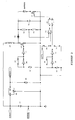
Figure 2 is the full electronic diagram of a charger according to the invention, showing the high simplicity of implementing the invention. -
Figure 3 is a timing diagram explaining the mechanism that allows the charger to self-adapt to the source fluctuations. -
Figure 4 is a variation of theFigure 2 diagram showing how switching an only one resistor allows to determine the threshold of discharging the capacitor depending on the battery type. - According with
Figure 1 , a charger using the invention method splits into : - a rough filtering block (11) useful for such fast fluctuating direct current power sources as a photovoltaic panel,
- a voltage stabilizing block (12) suitable for providing stable voltage to the charger control logic parts,
- a DC/DC conversion stage (13) suitable for step charging a storage capacitor (14) up to a predetermined energy level though tolerating fluctuations of the source,
- a controlled switch (15) suitable for discharging the capacitor (14) into the battery (16),
- a comparator device (17) that triggers the switch (15) as soon as the predetermined level of energy is attained.
- According to the invention, the source may exhibit substantial fluctuations without compromising the quality of the battery charge.
- A first example of such fluctuation can be of changing the direct current primary source.
- So, such a charger input may be indifferently hooked to:
- various battery types within a large range of nominal voltage and capacity,
- various types of "adapters" (rectifiers) operated from the mains AC current, and not necessarily stabilized,
- various types of photovoltaic cells.
- Charging a battery from a « panel » assembly of photovoltaic cells is an especially attractive application of the invention.
- It is well known that a photovoltaic cell behaves as a constant current source under a constant light flow level, but exhibits significant fluctuations when the light flow varies on short or long term condition (time of day, orientation, moisture). The description thereafter shows how the charger reacts quite instantly to such variations of the available input power.
- Bicycle lighting - an obvious safety issue - is another typical application of the invention.
- Conventional bicycle lighting systems use a so-called "dynamo" (that is, a small size alternator) to directly power front and back lights. This "dynamo" is by essence a very fluctuating source, so that the user has poor or no light at low speed.
- A well-known alternative is to power the bicycle lights from batteries, allowing continuous lighting regardless of the speed. Conversely the user has the burden of changing or charging the batteries in due time; otherwise, batteries exhaustion results in no lighting at all.
- The best of both systems can be achieved by means of the invention. By means of a well known diode full bridge rectifier or by means of a well-know diodes and capacitors voltage multiplier, the "dynamo" will source fluctuating DC current.
- In turn, the charger shall be hooked to the lamp batteries therefore compensating the lamp consumption and/or charging those batteries depending on the instant speed.
- The bicycle user thus benefits from both an autonomous energy source (the "dynamo") and a continuous lighting (from batteries).
-
Figure 2 is the electronic schematic of a fully documented implementation of the invention supporting as a source: - any type of battery within a voltage range from 5.6 volt up to more than 12 volt, or
- any type of mains "adapter" (rectifier) - possibly unfiltered - within the same voltage range, or
- any photovoltaic panel experiencing voltage variation within the same range,
- The rough filtering block comprises an only one low voltage capacitor (21); the only constraint is to filter source disturbances too short to be absorbed by the control logic or the DC/DC converting stage.
- The voltage stabilizing block uses an integrated, serial regulator (22) of known type and a filter capacitor (23) so as to provide a stable 5 volt to the control logic parts, which are specified for this voltage (named HCMOS and TTL technologies).
- Such filtering and supply blocks are fully known and play only a utility role in the invention.
- The DC/DC converter and step-charging stage is built from:
- a "RC" oscillator based on a "Schmidt trigger" type inverter (24) providing a symmetric clock signal output which frequency is set by the resistor (25) and the capacitor (26),
- an inverter (27) playing the role of a buffer for the said clock signal and controlling a MOSFET type switching transistor (28),
- an inductive coil (29) that reacts under high voltage pulses form to the primary current cut-off by the transistor (28),
- a protection and rectifying diode (30) that step charges the storage capacitor (31) from the said high voltage pulses.
- Generating high voltage pulses by reaction to current cut-off within an inductive coil is in itself a well known technique.
- With the parts as in the thereafter list, the clock frequency is nearly 65 kHz (not critical) and the voltage over the storage capacitor (31) would reach more than 150 volt if it were not timely discharged into the battery under control of the comparator stage that triggers the MOSFET type transistor (32) acting as a switch.
- The comparator stage comprises a differential amplifier (33); the comparator inputs are polarized respectively:
- by the divider bridge made of the resistors (34) and (35), reflecting the voltage over the storage capacitor (31) terminals,
- by the equal resistors (36) and (37) acting as a divider by half of the logic supply, that is 2.5 volt.
- The values if the (34) and (35) resistors are so chosen as to:
- ensure that the voltage into the (33) amplifier does not exceed the supply voltage of this amplifier (which could damage it), and
- provide a voltage slightly greater than the 2.5 volt reference voltage when the voltage over the storage capacitor terminal exceeds a predetermined, triggering threshold.
- As an example a triggering threshold of roughly 25 volt has been found empirically convenient for charging a 12 volt nominal lead/acid battery.
- The control pulse for the discharge switching transistor (32) is generated by means of another "RC" symmetrical, sampling clock generated by a "Schmidt-trigger" inverter (38); its frequency is set by the resistor (39) end the capacitor (40). This clock signal is buffered by the inverter (41).
- When the comparator (33) detects a voltage exceeding the predetermined voltage threshold for discharge, a half period of the latter clock is locked by means of the "D" type flip-flop (42); its "Q" output triggers on the transistor (32).
- Using the chosen parts the trigger clock has roughly a 1 kHz frequency and therefore a half-period of 500 µs (not critical) empirically found long enough to secure the discharge of the storage capacitor down to the instant battery voltage.
- The thereafter list names all electronic parts used for the example implementation as described by the
Figure 3 schematic diagram. - A person skilled in the art will view those parts as commonplace, low cost and available from numerous sources:
- filter capacitor (21): 1000
µF 36 volt, - logic voltage regulator (22): integrated 78L05 circuit,
- logic voltage filter capacitor (23): 100
µF 36 volt, - induction coil (29): 50 µH,
- rectifying diode (30): 1N4007,
- storage capacitor (31): 100 µF 160 volt,
- "Schmidt trigger" inverters (24) (27) (38) and (41): four gates from an only one 74CH14 integrated circuit,
- step charging oscillator resistor (25) and capacitor (26): 2,2 k ohm et 10 nF respectively,
- discharge pulse oscillator resistor (39) and capacitor (40): 10 k ohm and 100 nF respectively,
- differential amplifier/comparator: LM324 integrated circuit,
- "D" type flip/flop (42): 74HC175 integrated circuit,
- MOSFET power transistors (36) and (37): IRF740,
- trigger threshold divider resistors (34) and (35): 100 k ohm and 10 k ohm respectively,
- reference voltage divider resistors (36) and (37): both 10 k ohm.
- The charger behaviour shall be described based on the
Figure 3 timing diagram, which shows a full cycle of operation. - On this timing diagram the horizontal coordinate is time, and the vertical, voltage coordinate shows two signals:
- the voltage (101) over the storage capacitor (31) terminals,
- the discharge trigger control signal (102) coming from the flip/flop (43).
- According to a non periodic cycle that begins after a capacitor discharge (
time 110a), this storage capacitor is step charged in ramp shape until the variable time (110b) when the voltage exceeds the predetermined threshold. - This event is detected by the comparator, resulting into a transistor control pulse of fixed time (120a) to (120b) allowing the capacitor discharge; this is the end of the cycle and the start of a new cycle.
- The step charge duration (110a) to (110b) depends on the instant power available from the source. This is because the high voltage pulses generating process yields a voltage that depends directly on the intensity of the current cut off according to the well known formula dU = L × dI / dt. Therefore the time to charge the storage capacitor up to the threshold is directly related to the available source current.
- In case the source is a photovoltaic cells panel exposed to the sun light, it is known that this panel behaves as a "current source" roughly proportional to the incoming light flow. Therefore the time to charge the storage capacitor will in turn be variable and essentially proportional to the said light flow at the moment.
- Conversely, the discharge control pulse duration and amplitude shall remain substantially stable. The maximum voltage over the storage capacitor is slightly variable, the only uncertainty factor being the sampling clock period.
- Therefore the objectives are met:
- on the one hand, self adaptation to the power available from a direct current source submitted to large fluctuations,
- on the other hand, a stable and insensitive to the source fluctuations quality of charge thanks to almost constant calibration of the discharge control pulses.
- This results from the invention characteristic combination of:
- a stage of voltage step up for step charging a storage capacitor,
- a comparator stage designed for triggering the said capacitor discharge into a battery when the voltage over the capacitor terminal exceeds a threshold predetermined as a function of the battery type.
- The charger described as an example in
Figure 2 performs charging of a nominal 12 volt lead/acid battery from a solar panel source so designed as to deliver 14 volt under best light condition, as soon as this source generates some 5.6 volt, that is, enough to activate the control logic through the regulator. - Depending on the lighting condition, full charge of the battery is attained in a global delay adapting itself to the light flow fluctuations, including under such conditions that would block existing chargers due to "insufficient" voltage over the solar source terminals and therefore would waste a significant amount of the available energy.
- It is feasible as well to deliberately « undersize » the photovoltaic source power (which cost per watt remains high) when much time is known to be available for charging a given battery, as in the case of sunny countries where sun light will be present all day long so as to provide night lighting from the battery.
- If desirable, charging various types of batteries of different technology or of different nominal voltage may be obtained through a slight change of the
Figure 2 diagram, introducing as inFigure 4 an additional switch for selecting various threshold voltages by means of inserting in the divider bridge one of the resistors (35a) (35b) (35c) etc. as a function of either foreseen battery type or model. - According to this variation the same charger is able to indifferently charging lead/acid, nickel cadmium of NiMH technology batteries etc. with various nominal voltages. Most existing chargers do not exhibit such a flexibility because they are designed for a given battery type and a given nominal voltage.
- People skilled in the art will notice evidence that sizing chargers in accordance with the invention only depends on properly sizing the following parts:
- the filtering and storage capacitors,
- the switching transistors (or parallel setup of such transistors),
- the induction coil,
- People skilled in the art may also add without questioning the domain of the invention various known features such as:
- a charge limiter causing source disconnection based on the battery voltage,
- thermal protection,
- state of charge display, etc.
- People skilled in the art will see as well that a load can be hooked on the battery terminals provided known safety features are used, without questioning the charger operation.
- At last, people skilled in the art will consider such low voltage logic parts as from the 3.3 volt standard for controls, since the lowest operation point only depends of having enough power to run the control logic. In case the source is photovoltaic, this allows battery charging from even lower light flow.
- The said control logic may obviously be implemented for large series within a single, dedicated circuit, integrating clocks generation and the functionality of comparing the voltage over the storage capacitor terminals with a predetermined (or switch chosen) threshold.
Claims (8)
- A method for charging a battery (16) from a direct-current source liable to significant fluctuations,- wherein the DC voltage from said direct-current source is step-up converted into a DC voltage which is higher than the nominal voltage of said battery and is applied for progressively charging a storage capacitorcomprising the steps of:- detecting a predetermined voltage threshold over the terminals of said storage capacitor (14), and ,- discharging said storage capacitor (14) into said battery (16) without disconnecting the capacitor from the source at discharge me, said discharging being controlled by said threshold detection.
- The method of claim 1, implemented for charging a battery from a photovoltaic cells source.
- The method of claim 1, implemented for electrically supplying a lighting equipment for a vehicle, from a bicycle dynamo-electric generator.
- A device for charging a battery (16) from a direct-current source liable to significant fluctuations, implementing the method according to any of preceding claims, comprising:- means (14) for storing capacitive energy,- means (13) for step up converting the DC voltage from said direct-current source into a DC voltage which is higher than the nominal voltage of said battery,- means (13) for progressively charging said capacitive storage means at said DC voltage provided by said converting means,- means (17) for detecting a predetermined voltage threshold over the terminals of said capacitive storage means (14), and- means (15) for discharging said capacitive storage means into said battery, without disconnecting the capacitor from the source at discharge time, said discharging means being controlled by said threshold detection means.
- The device of claim 4, characterized in that it further comprises filtering means (11) arranged between said direct-current source and said progressively-charging means (13).
- The device according to claim 4 or 5, characterized in that it further comprises means for adapting the predetermined voltage threshold at the terminals of said capacitive storage means (14), in function of the type of battery to be charged.
- The device according to claim 6, characterized in that the threshold-adapting means comprise a commutable resistor (35a, 35b, 35c).
- The device of any of claims 4 to 7, characterized in that the progressively-charging means (13) comprise inductive storage means (29) cooperating with controlled switching means (28).
Applications Claiming Priority (2)
| Application Number | Priority Date | Filing Date | Title |
|---|---|---|---|
| FR0403012A FR2868218A1 (en) | 2004-03-23 | 2004-03-23 | METHOD AND DEVICE FOR PULSE BATTERY CHARGING TOLERATING FLUCTUATIONS OF A CONTINUOUS CURRENT SOURCE |
| PCT/EP2005/003059 WO2005091462A1 (en) | 2004-03-23 | 2005-03-22 | Method and device tolerant to direct current source fluctuation for pulse charging a battery |
Publications (2)
| Publication Number | Publication Date |
|---|---|
| EP1733464A1 EP1733464A1 (en) | 2006-12-20 |
| EP1733464B1 true EP1733464B1 (en) | 2010-06-30 |
Family
ID=34967917
Family Applications (1)
| Application Number | Title | Priority Date | Filing Date |
|---|---|---|---|
| EP05716304A Expired - Lifetime EP1733464B1 (en) | 2004-03-23 | 2005-03-22 | Method and device tolerant to direct current source fluctuation for pulse charging a battery |
Country Status (6)
| Country | Link |
|---|---|
| US (1) | US7928700B2 (en) |
| EP (1) | EP1733464B1 (en) |
| AT (1) | ATE472842T1 (en) |
| DE (1) | DE602005022059D1 (en) |
| FR (1) | FR2868218A1 (en) |
| WO (1) | WO2005091462A1 (en) |
Families Citing this family (24)
| Publication number | Priority date | Publication date | Assignee | Title |
|---|---|---|---|---|
| FR2891094A1 (en) * | 2005-09-20 | 2007-03-23 | Jean Michel Cour | Battery charging method, involves tracking maximum power point of source by indirectly measuring consumed power and modulating duty factor of input stage based on measurement of consumed power |
| US20080258674A1 (en) * | 2007-04-23 | 2008-10-23 | David Hui | Quickly charging power supply apparatus |
| EP2081274A2 (en) | 2007-12-07 | 2009-07-22 | Reelight APS | Electric driver circuit for bi-cycle applications |
| MY159639A (en) * | 2008-07-09 | 2017-01-13 | Access Business Group Int Llc | Wireless charging system |
| GB0814414D0 (en) * | 2008-08-06 | 2008-09-10 | G24 Innovations Ltd | Recharging batteries |
| GB0814415D0 (en) * | 2008-08-06 | 2008-09-10 | G24 Innovations Ltd | Recharging batteries |
| DE102008044902A1 (en) * | 2008-08-29 | 2010-03-04 | Siemens Aktiengesellschaft | Apparatus and method for generating, storing and transmitting electrical energy |
| FR2936110B1 (en) | 2008-09-16 | 2010-10-01 | Commissariat Energie Atomique | AUTONOMOUS SYSTEM COMPRISING A BATTERY AND A SUPERCAPACITY AND A CHARGING METHOD. |
| US8143845B2 (en) * | 2008-12-17 | 2012-03-27 | Fairchild Semiconductor Corporation | Cable voltage drop compensation for battery chargers |
| US8183834B2 (en) * | 2009-01-28 | 2012-05-22 | Atmel Corporation | Current to frequency conversion, apparatus and methods |
| US8773083B2 (en) | 2011-01-24 | 2014-07-08 | Sunrise Micro Devices, Inc. | Detection of insufficient current sourcing capability of supplied power |
| US10007286B2 (en) | 2011-01-24 | 2018-06-26 | Sunrise Micro Devices, Inc. | Switching regulator overload detector |
| JP2013038941A (en) * | 2011-08-09 | 2013-02-21 | Nippon Dengyo Kosaku Co Ltd | Charge voltage control circuit and power supply circuit |
| FR2984033B1 (en) * | 2011-12-13 | 2015-04-17 | Intesens | ELECTRIC POWER TRANSFER DEVICE, ELECTRIC POWER GENERATING AND STORAGE SYSTEM, AND TELEMETRY APPARATUS |
| JP5829999B2 (en) * | 2012-11-12 | 2015-12-09 | Fdk株式会社 | Charger |
| US10121533B2 (en) | 2012-11-21 | 2018-11-06 | Nano-Retina, Inc. | Techniques for data retention in memory cells during power interruption |
| US9720477B2 (en) * | 2012-11-21 | 2017-08-01 | Nano-Retina, Inc. | Weak power supply operation and control |
| US9536205B2 (en) * | 2013-01-24 | 2017-01-03 | Nec Corporation | Adaptive control of hybrid ultracapacitor-battery storage system for photovoltaic output smoothing |
| US10374447B2 (en) * | 2013-03-14 | 2019-08-06 | Infineon Technologies Austria Ag | Power converter circuit including at least one battery |
| CN103312001B (en) * | 2013-06-25 | 2015-03-25 | 安科智慧城市技术(中国)有限公司 | Battery-charging method and system with super capacitor for energy storage system |
| TWI489760B (en) * | 2013-07-03 | 2015-06-21 | Richtek Technology Corp | Voltage converter controller and voltage converter circuit with voltage drops compensation |
| US9966790B2 (en) | 2013-08-21 | 2018-05-08 | University Of North Dakota | Conformal body capacitors suitable for vehicles |
| JP6176791B2 (en) * | 2014-02-28 | 2017-08-09 | 浩平 速水 | Environmental energy storage system |
| US10205374B2 (en) | 2016-02-01 | 2019-02-12 | Toan Cong Tran | Tran principles, methods of DC pulse electric device without moving parts |
Family Cites Families (8)
| Publication number | Priority date | Publication date | Assignee | Title |
|---|---|---|---|---|
| US685957A (en) | 1901-03-21 | 1901-11-05 | Nikola Tesla | Apparatus for the utilization of radiant energy. |
| DK160359C (en) | 1986-11-14 | 1991-08-12 | Herluf Jakob Larsen | LIGHTING FOR A BIKE |
| DE9309287U1 (en) * | 1993-06-22 | 1993-08-19 | Bauer, Michael, Dipl.-Phys., 76337 Waldbronn | Solar charger for charging bicycle accumulators |
| JP3019248B2 (en) * | 1995-11-17 | 2000-03-13 | 重雄 山本 | Portable power supply with battery charger |
| US5747967A (en) | 1996-02-22 | 1998-05-05 | Midwest Research Institute | Apparatus and method for maximizing power delivered by a photovoltaic array |
| DE19617397A1 (en) * | 1996-05-02 | 1997-11-13 | Manfred Schwitajewski | Charging up lead/acid batteries by solar cells |
| TW472426B (en) * | 1998-10-06 | 2002-01-11 | Hitachi Ltd | Battery apparatus and control system therefor |
| US6677730B2 (en) | 2001-12-21 | 2004-01-13 | Energenx, Inc. | Device and method for pulse charging a battery and for driving other devices with a pulse |
-
2004
- 2004-03-23 FR FR0403012A patent/FR2868218A1/en active Pending
-
2005
- 2005-03-22 AT AT05716304T patent/ATE472842T1/en not_active IP Right Cessation
- 2005-03-22 DE DE602005022059T patent/DE602005022059D1/en not_active Expired - Lifetime
- 2005-03-22 EP EP05716304A patent/EP1733464B1/en not_active Expired - Lifetime
- 2005-03-22 US US10/593,825 patent/US7928700B2/en not_active Expired - Fee Related
- 2005-03-22 WO PCT/EP2005/003059 patent/WO2005091462A1/en not_active Ceased
Also Published As
| Publication number | Publication date |
|---|---|
| WO2005091462A1 (en) | 2005-09-29 |
| EP1733464A1 (en) | 2006-12-20 |
| US20070222411A1 (en) | 2007-09-27 |
| FR2868218A1 (en) | 2005-09-30 |
| US7928700B2 (en) | 2011-04-19 |
| DE602005022059D1 (en) | 2010-08-12 |
| ATE472842T1 (en) | 2010-07-15 |
Similar Documents
| Publication | Publication Date | Title |
|---|---|---|
| EP1733464B1 (en) | Method and device tolerant to direct current source fluctuation for pulse charging a battery | |
| US5498951A (en) | Method and apparatus for charging electric double layer capacitor | |
| US5254929A (en) | Intermediate storage battery charging system | |
| KR101197243B1 (en) | Portable Power Supply Device | |
| KR101516193B1 (en) | Apparatus for controlling solar charging and method therefor | |
| EP2343788A2 (en) | Power control system and method for charging battery using fluctuating power source | |
| CN103545907B (en) | Office photovoltaic DC power-supply system and control method | |
| CN111146847B (en) | A charging and discharging protection circuit for a lithium battery management system and a lithium battery management system | |
| CN203690963U (en) | Portable energy storage power supply | |
| JP2004064855A (en) | Power supply using photocell | |
| JP4977805B1 (en) | Stand-alone power supply | |
| JP2003209936A (en) | Charger for solar battery powered mobile device | |
| CN201341036Y (en) | Intelligent charger controller for electromobile | |
| JPH0738130A (en) | Storage Battery Control Method for Solar Power System | |
| RU2726735C1 (en) | Self-contained power supply system with combined energy storage unit | |
| JPH08308144A (en) | Portable battery with battery charger | |
| CN106100066B (en) | A kind of miniature charging station of thin film solar | |
| CN206472357U (en) | A solar street light device with external charging function | |
| CN221978665U (en) | Dual-power switching charging circuit | |
| CN221177979U (en) | Photovoltaic power supply street lamp of intelligent regulation load | |
| CN217036822U (en) | Solar power supply device for children electric toy | |
| JPH09215224A (en) | Portable power supply unit with battery charger | |
| CN114499153B (en) | PFC output slow start circuit and PFC output slow start time sequence control method | |
| CN214543765U (en) | Auxiliary power supply timely control device for unmanned automatic weather station | |
| CN216252238U (en) | Charging starting circuit for BMS battery management system and electric vehicle |
Legal Events
| Date | Code | Title | Description |
|---|---|---|---|
| PUAI | Public reference made under article 153(3) epc to a published international application that has entered the european phase |
Free format text: ORIGINAL CODE: 0009012 |
|
| 17P | Request for examination filed |
Effective date: 20061019 |
|
| AK | Designated contracting states |
Kind code of ref document: A1 Designated state(s): AT BE BG CH CY CZ DE DK EE ES FI FR GB GR HU IE IS IT LI LT LU MC NL PL PT RO SE SI SK TR |
|
| AX | Request for extension of the european patent |
Extension state: AL BA HR LV MK YU |
|
| GRAP | Despatch of communication of intention to grant a patent |
Free format text: ORIGINAL CODE: EPIDOSNIGR1 |
|
| GRAS | Grant fee paid |
Free format text: ORIGINAL CODE: EPIDOSNIGR3 |
|
| 111L | Licence recorded |
Free format text: 0101 TUNECHARGER S.A.S. Effective date: 20100303 |
|
| RAP1 | Party data changed (applicant data changed or rights of an application transferred) |
Owner name: COUR, ESTHER Owner name: MARTY, MARGUERITE ANNIE Owner name: COUR, EDOUARD Owner name: COUR, SOPHIE |
|
| RIN1 | Information on inventor provided before grant (corrected) |
Inventor name: COUR, EDOUARD Inventor name: COUR, ESTHER Inventor name: MARTY, MARGUERITE ANNIE Inventor name: COUR, SOPHIE |
|
| GRAA | (expected) grant |
Free format text: ORIGINAL CODE: 0009210 |
|
| AK | Designated contracting states |
Kind code of ref document: B1 Designated state(s): AT BE BG CH CY CZ DE DK EE ES FI FR GB GR HU IE IS IT LI LT LU MC NL PL PT RO SE SI SK TR |
|
| AX | Request for extension of the european patent |
Extension state: AL BA HR LV MK YU |
|
| REG | Reference to a national code |
Ref country code: GB Ref legal event code: FG4D Ref country code: CH Ref legal event code: EP Ref country code: CH Ref legal event code: PK Free format text: ERGAENZUNG LIZENZEINTRAG: NICHT AUSSCHLIESSLICHE LIZENZ |
|
| REG | Reference to a national code |
Ref country code: IE Ref legal event code: FG4D |
|
| REF | Corresponds to: |
Ref document number: 602005022059 Country of ref document: DE Date of ref document: 20100812 Kind code of ref document: P |
|
| REG | Reference to a national code |
Ref country code: NL Ref legal event code: VDEP Effective date: 20100630 |
|
| PG25 | Lapsed in a contracting state [announced via postgrant information from national office to epo] |
Ref country code: LT Free format text: LAPSE BECAUSE OF FAILURE TO SUBMIT A TRANSLATION OF THE DESCRIPTION OR TO PAY THE FEE WITHIN THE PRESCRIBED TIME-LIMIT Effective date: 20100630 Ref country code: SE Free format text: LAPSE BECAUSE OF FAILURE TO SUBMIT A TRANSLATION OF THE DESCRIPTION OR TO PAY THE FEE WITHIN THE PRESCRIBED TIME-LIMIT Effective date: 20100630 |
|
| LTIE | Lt: invalidation of european patent or patent extension |
Effective date: 20100630 |
|
| PG25 | Lapsed in a contracting state [announced via postgrant information from national office to epo] |
Ref country code: AT Free format text: LAPSE BECAUSE OF FAILURE TO SUBMIT A TRANSLATION OF THE DESCRIPTION OR TO PAY THE FEE WITHIN THE PRESCRIBED TIME-LIMIT Effective date: 20100630 Ref country code: SI Free format text: LAPSE BECAUSE OF FAILURE TO SUBMIT A TRANSLATION OF THE DESCRIPTION OR TO PAY THE FEE WITHIN THE PRESCRIBED TIME-LIMIT Effective date: 20100630 Ref country code: FI Free format text: LAPSE BECAUSE OF FAILURE TO SUBMIT A TRANSLATION OF THE DESCRIPTION OR TO PAY THE FEE WITHIN THE PRESCRIBED TIME-LIMIT Effective date: 20100630 |
|
| PG25 | Lapsed in a contracting state [announced via postgrant information from national office to epo] |
Ref country code: PL Free format text: LAPSE BECAUSE OF FAILURE TO SUBMIT A TRANSLATION OF THE DESCRIPTION OR TO PAY THE FEE WITHIN THE PRESCRIBED TIME-LIMIT Effective date: 20100630 Ref country code: GR Free format text: LAPSE BECAUSE OF FAILURE TO SUBMIT A TRANSLATION OF THE DESCRIPTION OR TO PAY THE FEE WITHIN THE PRESCRIBED TIME-LIMIT Effective date: 20101001 |
|
| PG25 | Lapsed in a contracting state [announced via postgrant information from national office to epo] |
Ref country code: NL Free format text: LAPSE BECAUSE OF FAILURE TO SUBMIT A TRANSLATION OF THE DESCRIPTION OR TO PAY THE FEE WITHIN THE PRESCRIBED TIME-LIMIT Effective date: 20100630 Ref country code: EE Free format text: LAPSE BECAUSE OF FAILURE TO SUBMIT A TRANSLATION OF THE DESCRIPTION OR TO PAY THE FEE WITHIN THE PRESCRIBED TIME-LIMIT Effective date: 20100630 |
|
| PG25 | Lapsed in a contracting state [announced via postgrant information from national office to epo] |
Ref country code: CY Free format text: LAPSE BECAUSE OF FAILURE TO SUBMIT A TRANSLATION OF THE DESCRIPTION OR TO PAY THE FEE WITHIN THE PRESCRIBED TIME-LIMIT Effective date: 20100630 Ref country code: BE Free format text: LAPSE BECAUSE OF FAILURE TO SUBMIT A TRANSLATION OF THE DESCRIPTION OR TO PAY THE FEE WITHIN THE PRESCRIBED TIME-LIMIT Effective date: 20100630 Ref country code: RO Free format text: LAPSE BECAUSE OF FAILURE TO SUBMIT A TRANSLATION OF THE DESCRIPTION OR TO PAY THE FEE WITHIN THE PRESCRIBED TIME-LIMIT Effective date: 20100630 Ref country code: PT Free format text: LAPSE BECAUSE OF FAILURE TO SUBMIT A TRANSLATION OF THE DESCRIPTION OR TO PAY THE FEE WITHIN THE PRESCRIBED TIME-LIMIT Effective date: 20101102 Ref country code: IS Free format text: LAPSE BECAUSE OF FAILURE TO SUBMIT A TRANSLATION OF THE DESCRIPTION OR TO PAY THE FEE WITHIN THE PRESCRIBED TIME-LIMIT Effective date: 20101030 Ref country code: CZ Free format text: LAPSE BECAUSE OF FAILURE TO SUBMIT A TRANSLATION OF THE DESCRIPTION OR TO PAY THE FEE WITHIN THE PRESCRIBED TIME-LIMIT Effective date: 20100630 Ref country code: SK Free format text: LAPSE BECAUSE OF FAILURE TO SUBMIT A TRANSLATION OF THE DESCRIPTION OR TO PAY THE FEE WITHIN THE PRESCRIBED TIME-LIMIT Effective date: 20100630 |
|
| PG25 | Lapsed in a contracting state [announced via postgrant information from national office to epo] |
Ref country code: DK Free format text: LAPSE BECAUSE OF FAILURE TO SUBMIT A TRANSLATION OF THE DESCRIPTION OR TO PAY THE FEE WITHIN THE PRESCRIBED TIME-LIMIT Effective date: 20100630 |
|
| PLBE | No opposition filed within time limit |
Free format text: ORIGINAL CODE: 0009261 |
|
| STAA | Information on the status of an ep patent application or granted ep patent |
Free format text: STATUS: NO OPPOSITION FILED WITHIN TIME LIMIT |
|
| 26N | No opposition filed |
Effective date: 20110331 |
|
| PG25 | Lapsed in a contracting state [announced via postgrant information from national office to epo] |
Ref country code: ES Free format text: LAPSE BECAUSE OF FAILURE TO SUBMIT A TRANSLATION OF THE DESCRIPTION OR TO PAY THE FEE WITHIN THE PRESCRIBED TIME-LIMIT Effective date: 20101011 |
|
| REG | Reference to a national code |
Ref country code: DE Ref legal event code: R097 Ref document number: 602005022059 Country of ref document: DE Effective date: 20110330 |
|
| PG25 | Lapsed in a contracting state [announced via postgrant information from national office to epo] |
Ref country code: MC Free format text: LAPSE BECAUSE OF NON-PAYMENT OF DUE FEES Effective date: 20110331 |
|
| REG | Reference to a national code |
Ref country code: CH Ref legal event code: PL |
|
| GBPC | Gb: european patent ceased through non-payment of renewal fee |
Effective date: 20110322 |
|
| REG | Reference to a national code |
Ref country code: FR Ref legal event code: ST Effective date: 20111130 |
|
| REG | Reference to a national code |
Ref country code: IE Ref legal event code: MM4A |
|
| PG25 | Lapsed in a contracting state [announced via postgrant information from national office to epo] |
Ref country code: LI Free format text: LAPSE BECAUSE OF NON-PAYMENT OF DUE FEES Effective date: 20110331 Ref country code: FR Free format text: LAPSE BECAUSE OF NON-PAYMENT OF DUE FEES Effective date: 20110331 Ref country code: IE Free format text: LAPSE BECAUSE OF NON-PAYMENT OF DUE FEES Effective date: 20110322 Ref country code: DE Free format text: LAPSE BECAUSE OF NON-PAYMENT OF DUE FEES Effective date: 20111001 Ref country code: CH Free format text: LAPSE BECAUSE OF NON-PAYMENT OF DUE FEES Effective date: 20110331 |
|
| REG | Reference to a national code |
Ref country code: DE Ref legal event code: R119 Ref document number: 602005022059 Country of ref document: DE Effective date: 20111001 |
|
| PG25 | Lapsed in a contracting state [announced via postgrant information from national office to epo] |
Ref country code: IT Free format text: LAPSE BECAUSE OF NON-PAYMENT OF DUE FEES Effective date: 20110322 Ref country code: GB Free format text: LAPSE BECAUSE OF NON-PAYMENT OF DUE FEES Effective date: 20110322 |
|
| PG25 | Lapsed in a contracting state [announced via postgrant information from national office to epo] |
Ref country code: LU Free format text: LAPSE BECAUSE OF NON-PAYMENT OF DUE FEES Effective date: 20110322 |
|
| PG25 | Lapsed in a contracting state [announced via postgrant information from national office to epo] |
Ref country code: BG Free format text: LAPSE BECAUSE OF FAILURE TO SUBMIT A TRANSLATION OF THE DESCRIPTION OR TO PAY THE FEE WITHIN THE PRESCRIBED TIME-LIMIT Effective date: 20100930 Ref country code: TR Free format text: LAPSE BECAUSE OF FAILURE TO SUBMIT A TRANSLATION OF THE DESCRIPTION OR TO PAY THE FEE WITHIN THE PRESCRIBED TIME-LIMIT Effective date: 20100630 |
|
| PG25 | Lapsed in a contracting state [announced via postgrant information from national office to epo] |
Ref country code: HU Free format text: LAPSE BECAUSE OF FAILURE TO SUBMIT A TRANSLATION OF THE DESCRIPTION OR TO PAY THE FEE WITHIN THE PRESCRIBED TIME-LIMIT Effective date: 20100630 |