EP1731940A1 - Zoom lens system and image pickup apparatus including the same - Google Patents
Zoom lens system and image pickup apparatus including the same Download PDFInfo
- Publication number
- EP1731940A1 EP1731940A1 EP06252875A EP06252875A EP1731940A1 EP 1731940 A1 EP1731940 A1 EP 1731940A1 EP 06252875 A EP06252875 A EP 06252875A EP 06252875 A EP06252875 A EP 06252875A EP 1731940 A1 EP1731940 A1 EP 1731940A1
- Authority
- EP
- European Patent Office
- Prior art keywords
- lens
- zoom lens
- zoom
- lens unit
- lens system
- Prior art date
- Legal status (The legal status is an assumption and is not a legal conclusion. Google has not performed a legal analysis and makes no representation as to the accuracy of the status listed.)
- Granted
Links
- 230000003287 optical effect Effects 0.000 claims abstract description 29
- 210000001747 pupil Anatomy 0.000 claims abstract description 12
- 239000000463 material Substances 0.000 claims abstract description 10
- 230000004075 alteration Effects 0.000 description 36
- 238000003384 imaging method Methods 0.000 description 8
- 230000005499 meniscus Effects 0.000 description 8
- 238000005549 size reduction Methods 0.000 description 6
- 230000001413 cellular effect Effects 0.000 description 3
- 238000010586 diagram Methods 0.000 description 2
- 230000004907 flux Effects 0.000 description 2
- 239000004973 liquid crystal related substance Substances 0.000 description 2
- 201000009310 astigmatism Diseases 0.000 description 1
- 230000008859 change Effects 0.000 description 1
- 238000006243 chemical reaction Methods 0.000 description 1
- 230000000295 complement effect Effects 0.000 description 1
- 239000006185 dispersion Substances 0.000 description 1
- 238000006073 displacement reaction Methods 0.000 description 1
- 230000006870 function Effects 0.000 description 1
- 239000011521 glass Substances 0.000 description 1
- 239000007788 liquid Substances 0.000 description 1
- 229910044991 metal oxide Inorganic materials 0.000 description 1
- 150000004706 metal oxides Chemical class 0.000 description 1
- 230000004048 modification Effects 0.000 description 1
- 238000012986 modification Methods 0.000 description 1
- 230000002093 peripheral effect Effects 0.000 description 1
- 239000010453 quartz Substances 0.000 description 1
- 239000011347 resin Substances 0.000 description 1
- 229920005989 resin Polymers 0.000 description 1
- 239000004065 semiconductor Substances 0.000 description 1
- VYPSYNLAJGMNEJ-UHFFFAOYSA-N silicon dioxide Inorganic materials O=[Si]=O VYPSYNLAJGMNEJ-UHFFFAOYSA-N 0.000 description 1
Images




Classifications
-
- G—PHYSICS
- G02—OPTICS
- G02B—OPTICAL ELEMENTS, SYSTEMS OR APPARATUS
- G02B13/00—Optical objectives specially designed for the purposes specified below
- G02B13/001—Miniaturised objectives for electronic devices, e.g. portable telephones, webcams, PDAs, small digital cameras
- G02B13/009—Miniaturised objectives for electronic devices, e.g. portable telephones, webcams, PDAs, small digital cameras having zoom function
-
- G—PHYSICS
- G02—OPTICS
- G02B—OPTICAL ELEMENTS, SYSTEMS OR APPARATUS
- G02B15/00—Optical objectives with means for varying the magnification
- G02B15/14—Optical objectives with means for varying the magnification by axial movement of one or more lenses or groups of lenses relative to the image plane for continuously varying the equivalent focal length of the objective
- G02B15/143—Optical objectives with means for varying the magnification by axial movement of one or more lenses or groups of lenses relative to the image plane for continuously varying the equivalent focal length of the objective having three groups only
- G02B15/1435—Optical objectives with means for varying the magnification by axial movement of one or more lenses or groups of lenses relative to the image plane for continuously varying the equivalent focal length of the objective having three groups only the first group being negative
- G02B15/143507—Optical objectives with means for varying the magnification by axial movement of one or more lenses or groups of lenses relative to the image plane for continuously varying the equivalent focal length of the objective having three groups only the first group being negative arranged -++
-
- G—PHYSICS
- G02—OPTICS
- G02B—OPTICAL ELEMENTS, SYSTEMS OR APPARATUS
- G02B15/00—Optical objectives with means for varying the magnification
- G02B15/14—Optical objectives with means for varying the magnification by axial movement of one or more lenses or groups of lenses relative to the image plane for continuously varying the equivalent focal length of the objective
- G02B15/16—Optical objectives with means for varying the magnification by axial movement of one or more lenses or groups of lenses relative to the image plane for continuously varying the equivalent focal length of the objective with interdependent non-linearly related movements between one lens or lens group, and another lens or lens group
- G02B15/177—Optical objectives with means for varying the magnification by axial movement of one or more lenses or groups of lenses relative to the image plane for continuously varying the equivalent focal length of the objective with interdependent non-linearly related movements between one lens or lens group, and another lens or lens group having a negative front lens or group of lenses
-
- G—PHYSICS
- G02—OPTICS
- G02B—OPTICAL ELEMENTS, SYSTEMS OR APPARATUS
- G02B13/00—Optical objectives specially designed for the purposes specified below
- G02B13/001—Miniaturised objectives for electronic devices, e.g. portable telephones, webcams, PDAs, small digital cameras
- G02B13/0015—Miniaturised objectives for electronic devices, e.g. portable telephones, webcams, PDAs, small digital cameras characterised by the lens design
- G02B13/002—Miniaturised objectives for electronic devices, e.g. portable telephones, webcams, PDAs, small digital cameras characterised by the lens design having at least one aspherical surface
- G02B13/004—Miniaturised objectives for electronic devices, e.g. portable telephones, webcams, PDAs, small digital cameras characterised by the lens design having at least one aspherical surface having four lenses
-
- G—PHYSICS
- G02—OPTICS
- G02B—OPTICAL ELEMENTS, SYSTEMS OR APPARATUS
- G02B13/00—Optical objectives specially designed for the purposes specified below
- G02B13/001—Miniaturised objectives for electronic devices, e.g. portable telephones, webcams, PDAs, small digital cameras
- G02B13/0015—Miniaturised objectives for electronic devices, e.g. portable telephones, webcams, PDAs, small digital cameras characterised by the lens design
- G02B13/002—Miniaturised objectives for electronic devices, e.g. portable telephones, webcams, PDAs, small digital cameras characterised by the lens design having at least one aspherical surface
- G02B13/0045—Miniaturised objectives for electronic devices, e.g. portable telephones, webcams, PDAs, small digital cameras characterised by the lens design having at least one aspherical surface having five or more lenses
Definitions
- the present invention relates to zoom lens systems suitable for, for example, compact image pickup apparatuses such as digital cameras and image pickup units for cellular phones and personal digital assistants (PDAs).
- compact image pickup apparatuses such as digital cameras and image pickup units for cellular phones and personal digital assistants (PDAs).
- PDAs personal digital assistants
- Image pickup apparatuses such as digital cameras and image pickup units for cellular phones and PDAs have an imaging optical system including an image pickup element such as a charge-coupled device (CCD) sensor or a complementary metal oxide semiconductor (CMOS) sensor.
- CCD charge-coupled device
- CMOS complementary metal oxide semiconductor
- a lens system with a relatively long back focus is demanded of the imaging optical system because it also includes various optical members, such as a low-pass filter and a color correction filter, between the image pickup element and the rearmost lens part.
- a compact, wide-angle lens system is demanded for size reduction of the entire apparatus using an image pickup element having a relatively small effective light-receiving area.
- Simple, compact zoom lenses for use in compact image pickup apparatuses are disclosed in, for example, Japanese Patent Laid-Open Nos. 2003-177314 (Patent Document 1), 2004-4765 (Patent Document 2), 2003-177315 (Patent Document 3), 2004-133058 (Patent Document 4), and 2004-318098 (Patent Document 5).
- These zoom lenses are negative-lead zoom lenses, including a frontmost lens unit with a negative refractive power.
- Zoom lenses according to embodiments disclosed in Patent Document 1 include only three lenses and exhibit poor optical performance.
- Zoom lenses according to embodiments disclosed in Patent Document 2 include six lenses and exhibit relatively good optical performance. These zoom lenses, however, have a large total lens length and are thus unsatisfactory in terms of size reduction.
- Lens systems according to embodiments disclosed in Patent Document 3 have a relatively high zoom ratio, namely, about 2.5x, but are unsatisfactory in terms of size reduction.
- Lens systems according to embodiments disclosed in Patent Document 4 are satisfactory in terms of size reduction, but have a relatively low zoom ratio, namely, about 2.0x.
- these lens systems are difficult to use directly for image pickup elements of optical apparatuses such as digital cameras because the systems are mainly intended for image pickup elements of cellular phones and PDAs.
- Lens systems according to embodiments disclosed in Patent Document 5 have a high zoom ratio, namely, about 3.0x to 5.0x, although these systems include many lenses and are thus unsatisfactory in terms of size reduction.
- a larger number of lenses of each lens unit included in a zoom lens increases the length of the lens unit along the optical axis thereof, and a larger amount of movement of each lens unit in zooming and focusing increases the total lens length of the zoom lens.
- the present invention provides a zoom lens system having a desired zoom ratio and high optical performance despite including fewer lenses.
- a zoom lens system as specified in claims 1 to 9.
- an image pickup apparatus as specified in claim 10.
- Fig. 1 is a sectional view of a zoom lens according to a first embodiment of the present invention.
- Fig. 2 is a set of graphs of aberrations caused at the wide-angle end of the zoom lens according to the first embodiment.
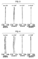
- Fig. 3 is a set of graphs of aberrations caused at an intermediate zoom position of the zoom lens according to the first embodiment.
- Fig. 4 is a set of graphs of aberrations caused at the telephoto end of the zoom lens according to the first embodiment.
- Fig. 5 is a sectional view of a zoom lens according to a second embodiment of the present invention.
- Fig. 6 is a set of graphs of aberrations caused at the wide-angle end of the zoom lens according to the second embodiment.
- Fig. 7 is a set of graphs of aberrations caused at an intermediate zoom position of the zoom lens according to the second embodiment.
- Fig. 8 is a set of graphs of aberrations caused at the telephoto end of the zoom lens according to the second embodiment.
- Fig. 9 is a sectional view of a zoom lens according to a third embodiment of the present invention.
- Fig. 10 is a set of graphs of aberrations caused at the wide-angle end of the zoom lens according to the third embodiment.
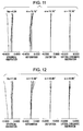
- Fig. 11 is a set of graphs of aberrations caused at an intermediate zoom position of the zoom lens according to the third embodiment.
- Fig. 12 is a set of graphs of aberrations caused at the telephoto end of the zoom lens according to the third embodiment.
- Fig. 13 is a schematic diagram of an image pickup apparatus according to an embodiment of the present invention.
- Fig. 1 is a sectional view of a zoom lens according to a first embodiment of the present invention at a wide-angle end (the end of the zoom range with the smallest focal length).
- Fig. 2 is a set of graphs of aberrations caused at the wide-angle end of the zoom lens.
- Fig. 3 is a set of graphs of aberrations caused at an intermediate zoom position of the zoom lens.
- Fig. 4 is a set of graphs of aberrations caused at the telephoto end of the zoom lens (the end of the zoom range with the largest focal length).
- the zoom lens according to the first embodiment has a zoom ratio of 2.82x and an F-number of about 2.95 to 5.44.
- Fig. 5 is a sectional view of a zoom lens according to a second embodiment of the present invention at the wide-angle end.
- Fig. 6 is a set of graphs of aberrations caused at the wide-angle end of the zoom lens.
- Fig. 7 is a set of graphs of aberrations caused at an intermediate zoom position of the zoom lens.
- Fig. 8 is a set of graphs of aberrations caused at the telephoto end of the zoom lens.
- the zoom lens according to the second embodiment has a zoom ratio of 2.83x and an F-number of about 2.95 to 5.48.
- Fig. 9 is a sectional view of a zoom lens according to a third embodiment of the present invention at the wide-angle end.
- Fig. 10 is a set of graphs of aberrations caused at the wide-angle end of the zoom lens.
- Fig. 11 is a set of graphs of aberrations caused at an intermediate zoom position of the zoom lens.
- Fig. 12 is a set of graphs of aberrations caused at the telephoto end of the zoom lens.
- the zoom lens according to the third embodiment has a zoom ratio of 2.83x and an F-number of about 3.99 to 7.46.
- Fig. 13 is a schematic diagram of a digital still camera (image pickup apparatus) including a zoom lens according to an embodiment of the present invention.
- the zoom lenses according to the embodiments are imaging lens systems for use in image pickup apparatuses.
- the left side of the zoom lens system is the object (front) side
- the right side is the image (rear) side.
- Zoom lens systems according to the present invention may also be applied to, for example, projection lenses for use in liquid crystal projectors.
- the front side of the systems corresponds to the screen side
- the rear side corresponds to the original image (liquid crystal panel) side.
- the zoom lenses each include a first lens unit L1 having a negative refractive power (an optical power represented as the reciprocal of focal length), a second lens unit L2 having a positive refractive power, a third lens unit L3 having a positive or negative refractive power, and an aperture stop (diaphragm) SP disposed on the object side of the second lens unit L2.
- the zoom lens also includes an optical block GB including an optical filter, a faceplate, a quartz low-pass filter, and an infrared cut filter, for example, and an image plane IP. If the zoom lens is used as an imaging optical system for camcorders or digital still cameras, an imaging surface of a solid-state image pickup element (photoelectric transducer), such as a CCD sensor or a CMOS sensor, is positioned in the image plane IP.
- a solid-state image pickup element photoelectric transducer
- fno indicates an F-number and ⁇ indicates a half-angle of view.
- the solid line indicates the d-line
- the chain line indicates the F-line
- the one-dot chain line indicates the C-line
- the two-dot chain line indicates the g-line.
- the solid line indicates a sagittal plane of the d-line
- the chain line indicates a meridional plane of the d-line
- the one-dot chain line indicates a sagittal plane of the g-line
- the two-dot chain line indicates a meridional plane of the g-line.
- the solid line indicates the d-line.
- the chain line indicates the F-line
- the one-dot chain line indicates the C-line
- the two-dot chain line indicates the g-line.
- the wide-angle end and the telephoto end refer to the zoom positions corresponding to the limits of a range in which a lens unit for changing magnification (the second lens unit L2) can be mechanically moved along the optical axis.
- the zoom lens according to each of the embodiments includes, in order from the object side to the image side, the first lens unit L1, the second lens unit L2, and the third lens unit L3.
- the first lens unit L1 is composed of a single negative lens G11.
- the zoom lens includes five or less lens elements in total.
- the zoom lens satisfies the following conditions: 58 ⁇ ⁇ d 1 0.10 ⁇ t k w / t l w ⁇ 0.70
- vd1 is the Abbe number of the material for the negative lens G11 of the first lens unit L1
- tkw is the exit pupil distance of the zoom lens at the wide-angle end
- tlw is the total lens length of the zoom lens at the wide-angle end.
- the exit pupil distance tkw is the distance from the rearmost lens surface to an exit pupil at the wide-angle end.
- the exit pupil distance tkw is positive if the exit pupil is positioned on the image side of the rearmost lens surface and is negative if the exit pupil is positioned on the object side of the rearmost lens surface.
- the total lens length tlw is the distance from the first lens surface (the frontmost lens surface) to the image plane IP.
- the condition (1) specifies the Abbe number of the material for the negative lens G11 of the first lens unit L1.
- a typical zoom lens corrects different types of aberrations within each lens unit to some extent to minimize variations in the aberrations occurring in zooming.
- the first lens unit L1 has difficulty in correcting the aberrations, particularly longitudinal chromatic aberration, by itself because the lens unit L1 is composed of the single negative lens G11.
- the zoom lens according to each of the embodiments allows longitudinal chromatic aberrations occurring in the first lens unit L1 and the other lens units to cancel each other out so that the aberrations can be balanced.
- Abbe numbers falling below the lower limit of the condition (1) are undesirable because variations in the longitudinal chromatic aberration occurring in the first lens unit L1 can no longer be successfully corrected using the other lens units.
- the numerical range of the condition (1) can be advantageously limited to the following range: ⁇ d 1 > 60
- the numerical range of the condition (1) can be further preferably limited to the following range: ⁇ d 1 > 80
- an extra-low-dispersion material is used for the negative lens G11 to successfully correct chromatic aberration.
- the material used is not limited to glass and may be any material, such as resin, that satisfies the condition (1).
- the condition (2) specifies the position of the exit pupil over the zoom lens. If the resultant value falls below the lower limit of the condition (2), the exit pupil is excessively close to the image plane IP at the wide-angle end. The zoom lens then undesirably provides insufficient peripheral brightness. If the resultant value exceeds the upper limit of the condition (2), the total lens length becomes undesirably large.
- the numerical range of the condition (2) can be advantageously limited to the following range: 0.20 ⁇ t k w / t l w ⁇ 0.50
- the zoom lens according to each of the embodiments further satisfies the following condition: 1.10 ⁇ f 1 / f w ⁇ 3.00 where f1 is the focal length of the first lens unit L1 and fw is the focal length of the entire system at the wide-angle end.
- the condition (3) specifies the focal length of the first lens unit L1. If the resultant value exceeds the upper limit of the condition (3), the zoom lens has a smaller total lens length, but undesirably poses difficulty in correcting aberrations, particularly distortion, over the zoom range thereof. If the resultant value falls below the lower limit of the condition (3), the amount of movement of the first lens unit L1 in zooming increases, and thus the total lens length becomes undesirably large.
- the numerical range of the condition (3) can be advantageously limited to the following range: 1.30 ⁇ f 1 / f w ⁇ 2.20
- the zoom lens according to each of the embodiments further satisfies the following condition: 0.01 ⁇ t l t ⁇ t l w / t l w ⁇ 0.15 where tlt is the total lens length of the zoom lens at the telephoto end.
- the condition (4) specifies the amount of movement of the lens unit L1 in zooming from the wide-angle end to the telephoto end. If the resultant value exceeds the upper limit of the condition (4), the zoom lens becomes undesirably long when retracted. If the resultant value falls below the lower limit of the condition (4), the lens units L1 to L3 have an excessively high refractive power and thus undesirably pose difficulty in correcting variations in aberrations occurring in zooming.
- the numerical range of the condition (4) can be advantageously limited to the following range: 0.02 ⁇ t l t ⁇ t l w / t l w ⁇ 0.10
- the zoom lens according to each of the embodiments further satisfies the following condition: 0.30 ⁇ f 3 / f w ⁇ f t ⁇ 2.00
- f3 is the focal length of the third lens unit L3
- fw is the focal length of the entire system at the wide-angle end
- ft is the focal length of the entire system at the telephoto end.
- the condition (5) specifies the focal length of the third lens unit L3. If the resultant value exceeds the upper limit of the condition (5), the third lens unit L3 has a low refractive power, and the amount of movement of the third lens unit L3 in zooming increases accordingly. As a result, the total length of the zoom lens becomes undesirably large. If the resultant value falls below the lower limit of the condition (5), the third lens unit L3 has an excessively high refractive power and thus undesirably poses difficulty in correcting aberrations over the zoom range.
- the numerical range of the condition (5) can be advantageously limited to the following range: 0.60 ⁇ f 3 / f w ⁇ f t ⁇ 1.80
- the zoom lens according to each of the embodiments further satisfies the following condition: 0.20 ⁇ f 2 / f w ⁇ f t ⁇ 1.00 where f2 is the focal length of the second lens unit L2.
- the condition (6) specifies the focal length of the second lens unit L2. If the resultant value exceeds the upper limit of the condition (6), the second lens unit L2 has a low refractive power, and the amount of movement of the second lens unit L2 in zooming increases accordingly. As a result, the total length of the zoom lens becomes undesirably large. If the resultant value falls below the lower limit of the condition (6), the second lens unit L2 has an excessively high refractive power and thus undesirably poses difficulty in correcting aberrations over the zoom range.
- the numerical range of the condition (6) can be advantageously limited to the following range: 0.50 ⁇ f 3 / f w ⁇ f t ⁇ 0.80
- the zoom lenses according to the first and second embodiments shown in Figs. 1 and 5, respectively, include, in order from the object side to the image side, the first lens unit L1, which has a negative refractive power, the second lens unit L2, which has a positive refractive power, and the third lens unit L3, which has a positive refractive power.
- the first lens unit L1 moves in a convex locus or path toward the image side, and the other two lens units L2 and L3 move toward the object side.
- the first lens unit L1, the third lens unit L3, or all lens units L1 to L3 move so as to extend the zoom lenses.
- the zoom lens according to the third embodiment shown in Fig. 9 includes, in order from the object side to the image side, the first lens unit L1, which has a negative refractive power, the second lens unit L2, which has a positive refractive power, and the third lens unit L3, which has a negative refractive power.
- the first lens unit L1 moves in a convex locus toward the image side, and the other two lens units L2 and L3 move toward the object side.
- the first lens unit L1, the third lens unit L3, or all lens units L1 to L3 move so as to extend the zoom lens.
- the first lens unit L1 is composed of the single negative lens G11, which has two aspherical concave surfaces.
- the frontmost lens thereof tends to have the largest diameter so that a luminous flux specifying the F-number of the zoom lens can enter the zoom lens.
- the effective lens diameter thereof must be increased to ensure entry of the required luminous flux.
- the first lens unit L1 may be composed of the minimum number of lenses, namely, a single lens.
- the first lens unit L1 moves toward and away from the image side in a convex path to successfully correct field curvature at the intermediate zoom position.
- the second lens unit L2 includes three lens elements in total.
- the second lens unit L2 includes, in order from the object side to the image side, a cemented lens including a biconvex positive lens and a meniscus negative lens having a concave surface on the object side and a meniscus negative lens having a concave surface on the image side.
- the second lens unit L2 includes, in order from the object side to the image side, a meniscus positive lens having a convex surface on the object side, a biconvex positive lens, and a meniscus negative lens having a concave surface on the image side.
- the second lens unit L2 includes, in order from the object side to the image side, a cemented lens including a biconvex positive lens and a meniscus negative lens having a concave surface on the object side and a meniscus negative lens having a concave surface on the object side.
- a positive lens is disposed on the frontmost side of the second lens unit L2 to decrease the angles of refraction of off-axis principal rays passing through the first lens unit L1, thus reducing off-axis aberrations.
- the aperture stop SP is disposed on the object side of the second lens unit L2 to reduce the distance between the first lens unit L1 and an entrance pupil at the wide-angle end. This arrangement inhibits an increase in the effective lens diameter of the first lens unit L1 and allows off-axis aberrations caused by the first lens unit L1 and the third lens unit L3 to cancel each other out.
- the second lens unit L2 which mainly serves to change magnification, moves to the object side to reduce variations in aberrations.
- the third lens unit L3 is composed of a single positive or negative lens.
- the third lens unit L3 is composed of a meniscus positive lens having a concave surface on the object side.
- the third lens unit L3 is composed of a meniscus negative lens having a concave surface on the image side.
- the third lens unit L3 moves to the object side to assist in changing magnification, thus contributing to the size reduction of the entire optical system.
- the zoom lenses according to the embodiments deliver excellent optical performance over the zoom range thereof despite including fewer lenses.
- inventions described above may also be applied to zoom lenses in which the distances between three lens units are changed in zooming by moving two of them (for example, first and second, first and third, or second and third lens units) rather than by moving all three lens units.
- another lens unit having a low refractive power may be disposed on the image side of the third lens unit L3.
- a digital still camera image pickup apparatus
- This digital still camera includes a zoom lens system according to the present invention as an imaging optical system.
- the digital still camera includes a camera body 20, an imaging optical system 21 including the zoom lens according to the present invention, a solid-state image pickup element (photoelectric transducer) 22, such as a CCD sensor or a CMOS sensor, incorporated in the camera body 20 to receive a subject image formed by the imaging optical system 21, a memory 23 for recording information on the subject image after photoelectric conversion by the image pickup element 22, and a viewfinder 24 including, for example, a liquid display panel to allow the observation of the subject image formed on the image pickup element 22.
- a solid-state image pickup element photoelectric transducer 22
- a viewfinder 24 including, for example, a liquid display panel to allow the observation of the subject image formed on the image pickup element 22.
- Zoom lens systems according to the present invention can thus be applied to image pickup apparatuses such as digital still cameras to provide compact image pickup apparatuses with high optical performance.
- x h 1 / r h 2 1 + 1 ⁇ 1 + k h / r 2 + A h 4 + B h 6 + C h 8 + D h 10 ⁇
- x is a displacement from the apex of the surface in the optical-axis direction
- h is a height from the optical axis in a direction perpendicular thereto
- r is a paraxial radius of curvature
- k is a conic constant
- B, C, D, E, and the subsequent symbols are aspherical coefficients of different orders.
- the two rearmost surfaces are flat surfaces (radius of curvature: ⁇ ) that define the optical block GB.
- Table 1 shows the resultant values of the conditions (1) to (6) in the embodiments.
Landscapes
- Physics & Mathematics (AREA)
- General Physics & Mathematics (AREA)
- Optics & Photonics (AREA)
- Nonlinear Science (AREA)
- Lenses (AREA)
Abstract


wherein vdl is the Abbe number of the material of the negative lens element, tkw is the distance from the rearmost lens surface to an exit pupil at a wide-angle end, and tlw is the total lens length of the zoom lens system at the wide-angle end.
Description
- The present invention relates to zoom lens systems suitable for, for example, compact image pickup apparatuses such as digital cameras and image pickup units for cellular phones and personal digital assistants (PDAs).
- Image pickup apparatuses such as digital cameras and image pickup units for cellular phones and PDAs have an imaging optical system including an image pickup element such as a charge-coupled device (CCD) sensor or a complementary metal oxide semiconductor (CMOS) sensor. A lens system with a relatively long back focus is demanded of the imaging optical system because it also includes various optical members, such as a low-pass filter and a color correction filter, between the image pickup element and the rearmost lens part. On the other hand, a compact, wide-angle lens system is demanded for size reduction of the entire apparatus using an image pickup element having a relatively small effective light-receiving area.
- Simple, compact zoom lenses for use in compact image pickup apparatuses are disclosed in, for example,
Japanese Patent Laid-Open Nos. 2003-177314 2004-4765 2003-177315 2004-133058 2004-318098 - Zoom lenses according to embodiments disclosed in Patent Document 1 include only three lenses and exhibit poor optical performance.
- Zoom lenses according to embodiments disclosed in Patent Document 2 include six lenses and exhibit relatively good optical performance. These zoom lenses, however, have a large total lens length and are thus unsatisfactory in terms of size reduction.
- Lens systems according to embodiments disclosed in Patent Document 3 have a relatively high zoom ratio, namely, about 2.5x, but are unsatisfactory in terms of size reduction.
- Lens systems according to embodiments disclosed in Patent Document 4 are satisfactory in terms of size reduction, but have a relatively low zoom ratio, namely, about 2.0x. In addition, these lens systems are difficult to use directly for image pickup elements of optical apparatuses such as digital cameras because the systems are mainly intended for image pickup elements of cellular phones and PDAs.
- Lens systems according to embodiments disclosed in Patent Document 5 have a high zoom ratio, namely, about 3.0x to 5.0x, although these systems include many lenses and are thus unsatisfactory in terms of size reduction.
- In general, a larger number of lenses of each lens unit included in a zoom lens increases the length of the lens unit along the optical axis thereof, and a larger amount of movement of each lens unit in zooming and focusing increases the total lens length of the zoom lens.
- The present invention provides a zoom lens system having a desired zoom ratio and high optical performance despite including fewer lenses.
- According to a first aspect of the present invention, there is provided a zoom lens system as specified in claims 1 to 9. According to a second aspect of the present invention, there is provided an image pickup apparatus as specified in claim 10.
- Further features of the present invention will become apparent from the following description of exemplary embodiments with reference to the attached drawings.
- Fig. 1 is a sectional view of a zoom lens according to a first embodiment of the present invention.
- Fig. 2 is a set of graphs of aberrations caused at the wide-angle end of the zoom lens according to the first embodiment.
- Fig. 3 is a set of graphs of aberrations caused at an intermediate zoom position of the zoom lens according to the first embodiment.
- Fig. 4 is a set of graphs of aberrations caused at the telephoto end of the zoom lens according to the first embodiment.
- Fig. 5 is a sectional view of a zoom lens according to a second embodiment of the present invention.
- Fig. 6 is a set of graphs of aberrations caused at the wide-angle end of the zoom lens according to the second embodiment.
- Fig. 7 is a set of graphs of aberrations caused at an intermediate zoom position of the zoom lens according to the second embodiment.
- Fig. 8 is a set of graphs of aberrations caused at the telephoto end of the zoom lens according to the second embodiment.
- Fig. 9 is a sectional view of a zoom lens according to a third embodiment of the present invention.
- Fig. 10 is a set of graphs of aberrations caused at the wide-angle end of the zoom lens according to the third embodiment.
- Fig. 11 is a set of graphs of aberrations caused at an intermediate zoom position of the zoom lens according to the third embodiment.
- Fig. 12 is a set of graphs of aberrations caused at the telephoto end of the zoom lens according to the third embodiment.
- Fig. 13 is a schematic diagram of an image pickup apparatus according to an embodiment of the present invention.
- Zoom lens systems and an image pickup apparatus according to embodiments of the present invention will now be described with reference to the drawings.
- Fig. 1 is a sectional view of a zoom lens according to a first embodiment of the present invention at a wide-angle end (the end of the zoom range with the smallest focal length). Fig. 2 is a set of graphs of aberrations caused at the wide-angle end of the zoom lens. Fig. 3 is a set of graphs of aberrations caused at an intermediate zoom position of the zoom lens. Fig. 4 is a set of graphs of aberrations caused at the telephoto end of the zoom lens (the end of the zoom range with the largest focal length). The zoom lens according to the first embodiment has a zoom ratio of 2.82x and an F-number of about 2.95 to 5.44.
- Fig. 5 is a sectional view of a zoom lens according to a second embodiment of the present invention at the wide-angle end. Fig. 6 is a set of graphs of aberrations caused at the wide-angle end of the zoom lens. Fig. 7 is a set of graphs of aberrations caused at an intermediate zoom position of the zoom lens. Fig. 8 is a set of graphs of aberrations caused at the telephoto end of the zoom lens. The zoom lens according to the second embodiment has a zoom ratio of 2.83x and an F-number of about 2.95 to 5.48.
- Fig. 9 is a sectional view of a zoom lens according to a third embodiment of the present invention at the wide-angle end. Fig. 10 is a set of graphs of aberrations caused at the wide-angle end of the zoom lens. Fig. 11 is a set of graphs of aberrations caused at an intermediate zoom position of the zoom lens. Fig. 12 is a set of graphs of aberrations caused at the telephoto end of the zoom lens. The zoom lens according to the third embodiment has a zoom ratio of 2.83x and an F-number of about 3.99 to 7.46.
- Fig. 13 is a schematic diagram of a digital still camera (image pickup apparatus) including a zoom lens according to an embodiment of the present invention.
- The zoom lenses according to the embodiments are imaging lens systems for use in image pickup apparatuses. In the sectional views of Figs. 1, 5, and 9, the left side of the zoom lens system is the object (front) side, and the right side is the image (rear) side. Zoom lens systems according to the present invention may also be applied to, for example, projection lenses for use in liquid crystal projectors. In such a case, the front side of the systems corresponds to the screen side and the rear side corresponds to the original image (liquid crystal panel) side.
- In the sectional views of Figs. 1, 5, and 9, the zoom lenses each include a first lens unit L1 having a negative refractive power (an optical power represented as the reciprocal of focal length), a second lens unit L2 having a positive refractive power, a third lens unit L3 having a positive or negative refractive power, and an aperture stop (diaphragm) SP disposed on the object side of the second lens unit L2.
- The zoom lens also includes an optical block GB including an optical filter, a faceplate, a quartz low-pass filter, and an infrared cut filter, for example, and an image plane IP. If the zoom lens is used as an imaging optical system for camcorders or digital still cameras, an imaging surface of a solid-state image pickup element (photoelectric transducer), such as a CCD sensor or a CMOS sensor, is positioned in the image plane IP.
- In the graphs of aberrations, fno indicates an F-number and ω indicates a half-angle of view. In the graphs of spherical aberration, the solid line indicates the d-line, the chain line indicates the F-line, the one-dot chain line indicates the C-line, and the two-dot chain line indicates the g-line. In the graphs of astigmatism, the solid line indicates a sagittal plane of the d-line, the chain line indicates a meridional plane of the d-line, the one-dot chain line indicates a sagittal plane of the g-line, and the two-dot chain line indicates a meridional plane of the g-line. In the graphs of distortion, the solid line indicates the d-line. In the graphs of lateral chromatic aberration, the chain line indicates the F-line, the one-dot chain line indicates the C-line, and the two-dot chain line indicates the g-line.
- In the description of the embodiments below, the wide-angle end and the telephoto end refer to the zoom positions corresponding to the limits of a range in which a lens unit for changing magnification (the second lens unit L2) can be mechanically moved along the optical axis.
- Features of the zoom lenses according to the embodiments are described below.
- The zoom lens according to each of the embodiments includes, in order from the object side to the image side, the first lens unit L1, the second lens unit L2, and the third lens unit L3. The first lens unit L1 is composed of a single negative lens G11. The zoom lens includes five or less lens elements in total. The zoom lens satisfies the following conditions:


where vd1 is the Abbe number of the material for the negative lens G11 of the first lens unit L1, tkw is the exit pupil distance of the zoom lens at the wide-angle end, and tlw is the total lens length of the zoom lens at the wide-angle end. It should be noted that the term "lens" herein refers to any optical element having a finite power. The exit pupil distance tkw is the distance from the rearmost lens surface to an exit pupil at the wide-angle end. The exit pupil distance tkw is positive if the exit pupil is positioned on the image side of the rearmost lens surface and is negative if the exit pupil is positioned on the object side of the rearmost lens surface. The total lens length tlw is the distance from the first lens surface (the frontmost lens surface) to the image plane IP. - The Abbe number νd1 is represented by the following equation:

where nd1, nF1, and nC1 are the refractive indices of the material for the negative lens G11 at the wavelengths of Fraunhofer lines, namely, the d-line, the F-line, and the C-line, respectively. - The condition (1) specifies the Abbe number of the material for the negative lens G11 of the first lens unit L1. A typical zoom lens corrects different types of aberrations within each lens unit to some extent to minimize variations in the aberrations occurring in zooming.
- The first lens unit L1, however, has difficulty in correcting the aberrations, particularly longitudinal chromatic aberration, by itself because the lens unit L1 is composed of the single negative lens G11.
- The zoom lens according to each of the embodiments allows longitudinal chromatic aberrations occurring in the first lens unit L1 and the other lens units to cancel each other out so that the aberrations can be balanced.
- Abbe numbers falling below the lower limit of the condition (1) are undesirable because variations in the longitudinal chromatic aberration occurring in the first lens unit L1 can no longer be successfully corrected using the other lens units.
- The numerical range of the condition (1) can be advantageously limited to the following range:

- The numerical range of the condition (1) can be further preferably limited to the following range:

- In the embodiments, as described above, an extra-low-dispersion material is used for the negative lens G11 to successfully correct chromatic aberration. The material used is not limited to glass and may be any material, such as resin, that satisfies the condition (1).
- The condition (2) specifies the position of the exit pupil over the zoom lens. If the resultant value falls below the lower limit of the condition (2), the exit pupil is excessively close to the image plane IP at the wide-angle end. The zoom lens then undesirably provides insufficient peripheral brightness. If the resultant value exceeds the upper limit of the condition (2), the total lens length becomes undesirably large.
- The numerical range of the condition (2) can be advantageously limited to the following range:

- The zoom lens according to each of the embodiments further satisfies the following condition:

where f1 is the focal length of the first lens unit L1 and fw is the focal length of the entire system at the wide-angle end. - The condition (3) specifies the focal length of the first lens unit L1. If the resultant value exceeds the upper limit of the condition (3), the zoom lens has a smaller total lens length, but undesirably poses difficulty in correcting aberrations, particularly distortion, over the zoom range thereof. If the resultant value falls below the lower limit of the condition (3), the amount of movement of the first lens unit L1 in zooming increases, and thus the total lens length becomes undesirably large.
- The numerical range of the condition (3) can be advantageously limited to the following range:

- The zoom lens according to each of the embodiments further satisfies the following condition:

where tlt is the total lens length of the zoom lens at the telephoto end. - The condition (4) specifies the amount of movement of the lens unit L1 in zooming from the wide-angle end to the telephoto end. If the resultant value exceeds the upper limit of the condition (4), the zoom lens becomes undesirably long when retracted. If the resultant value falls below the lower limit of the condition (4), the lens units L1 to L3 have an excessively high refractive power and thus undesirably pose difficulty in correcting variations in aberrations occurring in zooming.
- The numerical range of the condition (4) can be advantageously limited to the following range:

- The zoom lens according to each of the embodiments further satisfies the following condition:

where f3 is the focal length of the third lens unit L3, fw is the focal length of the entire system at the wide-angle end, and ft is the focal length of the entire system at the telephoto end. - The condition (5) specifies the focal length of the third lens unit L3. If the resultant value exceeds the upper limit of the condition (5), the third lens unit L3 has a low refractive power, and the amount of movement of the third lens unit L3 in zooming increases accordingly. As a result, the total length of the zoom lens becomes undesirably large. If the resultant value falls below the lower limit of the condition (5), the third lens unit L3 has an excessively high refractive power and thus undesirably poses difficulty in correcting aberrations over the zoom range.
- The numerical range of the condition (5) can be advantageously limited to the following range:

- The zoom lens according to each of the embodiments further satisfies the following condition:

- The condition (6) specifies the focal length of the second lens unit L2. If the resultant value exceeds the upper limit of the condition (6), the second lens unit L2 has a low refractive power, and the amount of movement of the second lens unit L2 in zooming increases accordingly. As a result, the total length of the zoom lens becomes undesirably large. If the resultant value falls below the lower limit of the condition (6), the second lens unit L2 has an excessively high refractive power and thus undesirably poses difficulty in correcting aberrations over the zoom range.
- The numerical range of the condition (6) can be advantageously limited to the following range:

- The zoom lenses according to the embodiments are specifically described below with reference to the drawings.
- The zoom lenses according to the first and second embodiments shown in Figs. 1 and 5, respectively, include, in order from the object side to the image side, the first lens unit L1, which has a negative refractive power, the second lens unit L2, which has a positive refractive power, and the third lens unit L3, which has a positive refractive power. In zooming from the wide-angle end to the telephoto end, the first lens unit L1 moves in a convex locus or path toward the image side, and the other two lens units L2 and L3 move toward the object side. In focusing, the first lens unit L1, the third lens unit L3, or all lens units L1 to L3 move so as to extend the zoom lenses.
- The zoom lens according to the third embodiment shown in Fig. 9 includes, in order from the object side to the image side, the first lens unit L1, which has a negative refractive power, the second lens unit L2, which has a positive refractive power, and the third lens unit L3, which has a negative refractive power. In zooming from the wide-angle end to the telephoto end, the first lens unit L1 moves in a convex locus toward the image side, and the other two lens units L2 and L3 move toward the object side. In focusing, the first lens unit L1, the third lens unit L3, or all lens units L1 to L3 move so as to extend the zoom lens.
- In each of the embodiments, the first lens unit L1 is composed of the single negative lens G11, which has two aspherical concave surfaces. For a general zoom lens including a first lens unit having a negative refractive power, the frontmost lens thereof tends to have the largest diameter so that a luminous flux specifying the F-number of the zoom lens can enter the zoom lens.
- If the first lens unit is composed of a plurality of lenses, the effective lens diameter thereof must be increased to ensure entry of the required luminous flux.
- In addition, as the lenses of the first lens unit have a larger curvature (a higher refractive power), they have a larger thickness and are separated by larger axial air spaces. Accordingly, the first lens unit L1 may be composed of the minimum number of lenses, namely, a single lens.
- In zooming, the first lens unit L1 moves toward and away from the image side in a convex path to successfully correct field curvature at the intermediate zoom position.
- In each of the embodiments, the second lens unit L2 includes three lens elements in total.
- In the first embodiment, the second lens unit L2 includes, in order from the object side to the image side, a cemented lens including a biconvex positive lens and a meniscus negative lens having a concave surface on the object side and a meniscus negative lens having a concave surface on the image side.
- In the second embodiment, the second lens unit L2 includes, in order from the object side to the image side, a meniscus positive lens having a convex surface on the object side, a biconvex positive lens, and a meniscus negative lens having a concave surface on the image side.
- In the third embodiment, the second lens unit L2 includes, in order from the object side to the image side, a cemented lens including a biconvex positive lens and a meniscus negative lens having a concave surface on the object side and a meniscus negative lens having a concave surface on the object side.
- In each of the embodiments, as described above, a positive lens is disposed on the frontmost side of the second lens unit L2 to decrease the angles of refraction of off-axis principal rays passing through the first lens unit L1, thus reducing off-axis aberrations. In addition, the aperture stop SP is disposed on the object side of the second lens unit L2 to reduce the distance between the first lens unit L1 and an entrance pupil at the wide-angle end. This arrangement inhibits an increase in the effective lens diameter of the first lens unit L1 and allows off-axis aberrations caused by the first lens unit L1 and the third lens unit L3 to cancel each other out.
- In zooming, the second lens unit L2, which mainly serves to change magnification, moves to the object side to reduce variations in aberrations.
- The third lens unit L3 is composed of a single positive or negative lens. In the first and second embodiments, the third lens unit L3 is composed of a meniscus positive lens having a concave surface on the object side. In the third embodiment, the third lens unit L3 is composed of a meniscus negative lens having a concave surface on the image side.
- In zooming, the third lens unit L3 moves to the object side to assist in changing magnification, thus contributing to the size reduction of the entire optical system.
- With the lens configurations described above, the zoom lenses according to the embodiments deliver excellent optical performance over the zoom range thereof despite including fewer lenses.
- The embodiments described above may also be applied to zoom lenses in which the distances between three lens units are changed in zooming by moving two of them (for example, first and second, first and third, or second and third lens units) rather than by moving all three lens units.
- In addition, another lens unit having a low refractive power may be disposed on the image side of the third lens unit L3.
- A digital still camera (image pickup apparatus) according to an embodiment of the present invention will be described below with reference to Fig. 13. This digital still camera includes a zoom lens system according to the present invention as an imaging optical system.
- In Fig. 13, the digital still camera includes a
camera body 20, an imagingoptical system 21 including the zoom lens according to the present invention, a solid-state image pickup element (photoelectric transducer) 22, such as a CCD sensor or a CMOS sensor, incorporated in thecamera body 20 to receive a subject image formed by the imagingoptical system 21, amemory 23 for recording information on the subject image after photoelectric conversion by theimage pickup element 22, and aviewfinder 24 including, for example, a liquid display panel to allow the observation of the subject image formed on theimage pickup element 22. - Zoom lens systems according to the present invention can thus be applied to image pickup apparatuses such as digital still cameras to provide compact image pickup apparatuses with high optical performance.
- Numerical data on the first to third embodiments of the present invention are shown below. In the data on the embodiments, i indicates the order of optical surfaces from the object side to the image side; ri indicates the radius of curvature of the i-th optical surface; di indicates the axial distance between the i-th and (i+1)th surfaces; ni indicates the refractive index of the material for the i-th optical element for the d-line; vi indicates the Abbe number of the material for the i-th optical element; f indicates a focal length; fno indicate an F-number; and ω indicates a half-angle of view.
- The shape of an aspherical surface is represented by the following equation:

wherein x is a displacement from the apex of the surface in the optical-axis direction, h is a height from the optical axis in a direction perpendicular thereto, r is a paraxial radius of curvature, k is a conic constant, and B, C, D, E, and the subsequent symbols are aspherical coefficients of different orders. - The symbol "D±XX" used in the values of aspherical coefficients refers to multiplication by 10 to the ±XX-th power. The symbol "asphi" indicates that the i-th surface has an aspherical shape.
- In the embodiments, the two rearmost surfaces are flat surfaces (radius of curvature: ∞) that define the optical block GB. Table 1 shows the resultant values of the conditions (1) to (6) in the embodiments.
-
f= 6.55005 ∼18.50976 fno=1: 2.95∼5.44 2ω= 56.91° ∼21.71° r 1= -1650.695 d 1= 1.00 n 1=1.43425 ν 1= 95.0 r 2= 5.654 d 2= Variable r 3= (Aperture) d 3= 0.15 r 4= 3.062 d 4= 3.33 n 2=1.59240 ν 2= 68.3 r 5= -2.457 d 5= 1.00 n 3=1.60970 ν 3= 57.8 r 6= -24.900 d 6= 0.54 r 7= 24.219 d 7= 1.00 n 4=2.00330 ν 4= 28.3 r 8= 3.341 d 8= Variable r 9= -34.161 d 9= 1.73 n 5=1.69320 ν 5= 33.7 r10= -6.806 d10= Variable r11= ∞ d11= 1.00 n 6=1.51633 ν 6= 64.1 r12= ∞ 
no asph 1 r-1.65069D+03 k-6.35771D+20 B-4.62747D-03 C3.39569D-04 D-1.18838D-05 E1.61985D-07 asph 2 r5.65440D+00 k-2.89909D+00 B-3.94637D-03 C3.57276D-04 D-9.93460D-6 E0.00000D+00 asph 4 r3.06208D+00 k-6.63995D-01 B1.65728D-03 C1.35204D-04 D-2.33714D-06 E2.66930D-06 asph 7 r2.42194D+01 k-2.28578D+03 B-1.25376D-02 C-1.89498D-02 D1.38343D-02 E-625315D-03 no asph 8 r3.34055D+00 k1.43887D+00 B-3.18311D-02 C2.01422D-03 D-4.41138D-04 E0.00000D+00 asph 9 r-3.41608D+01 k-9.81585D+02 B2.76159D-03 C1.19125D-03 D-8.52723D-05 E0.00000D+00 asph 10 r-6.80610D+00 k-1.83610D+00 B8.51306D04 C2.44700D-04 D4.24945D-05 E0.00000D+00 -
f= 6. 55022 ∼18.51052 fno=1 : 2.95∼5.48 2ω=56.91°∼21.71° r 1= -1297.328 d 1= 1.00 n 1=1.43425 ν 1= 95.0 r 2= 5.825 d 2= Variable r 3= (Aperture) d 3= 0.15 r 4= 3.085 d 4= 2.12 n 2=1.56907 ν 2= 71. 3 r 5= 92.239 d 5= 0.68 r 6= 12.015 d 6= 1.65 n 3=1.43425 ν 3= 95.0 r 7= -11.330 d 7= 0.15 r 8= 73.097 d 8= 1.00 n 4=2.00330 ν 4= 28.3 r 9= 3.362 d 9 = Variable r10= -18.925 d10= 1.57 n 5=1.90680 ν 5= 21.2 r11= -9.145 d11=Variable r12= ∞ d12= 1.00 n 6=1.51633 ν 6= 64.1 r13= ∞ 
no asph 1 r-1.29733D+03 k-7.03043D+20 B-4.88347D-03 C3.66090-04 D-1.27745D-05 E1.81740D-07 asph 2 r5.82529D+00 k-6.24871D+00 B-2.34942D-03 C2.51874D-04 D-5.72564D-06 E0.00000D+00 asph 4 r3.08475D+00 k-7.91850D-01 B1.26893D-03 C9.20108D-05 D9.36884D-06 E0.00000D+00 asph 5 r9.22388D+01 k-6.40865D+03 B1.42632D-03 C7.07792-D05 D4.59889D-05 E0.00000D+00 no asph 6 r1.20152D+01 k3.40860D+01 B3.79165D-03 C2.79351D-04 D0.00000D+00 E0.00000D+00 asph 7 r-1.13296D+01 k5.20987D+01 B-1.23155D-02 C-5.60822D-03 D2.83344D-03 E0.00000D+00 asph 8 r7.30974D+01 k-4.91272D+04 B-3.81304D02 C-1.79743D-02 D1.37313D-02 E-5.95963D-03 asph 9 r3.36157D+00 k6.37297D-01 B-4.08260D-02 C6.08501D-03 D-4.70385D-04 E0.00000D+00 -
f= 6. 55004 ∼18.50973 fno=1 : 3.99∼7.46 2ω=56.91° ∼21.71° r 1= -75.378 d 1= 1. 00 n 1=1.43425 ν 1= 95.0 r 2= 4. 625 d 2= Variable r 3= (Aperture) d 3= 0.10 r 4= 3.783 d 4= 2.95 n 2=1.48563 ν 2= 85.2 r 5= -4.850 d 5= 1.00 n 3=1.83500 ν 3= 43.0 r 6= -8.289 d 6= 0.71 r 7= -33. 622 d 7= 1.57 n 4=1.43425 ν 4= 95.0 r 8= -15.669 d 8= Variable r 9= 5.169 d 9= 1.00 n 5=1.77250 ν 5= 49.6 r10= 2. 654 d10=Variable r11= ∞ d11= 1.00 n 6=1.51633 ν 6= 64.1 r12= ∞ 
asph 1 r-7.53778D+01 k-3.04304D+03 B0.00000D+00 C0.00000D+00 D0.00000D+00 E0.00000D+00 asph 2 r4.62468D+00 k2.20884D-01 B2.91753D-04 C-9.51856D-05 D0.00000D+00 E0.00000D+00 asph 4 r3.78283D+00 k1.73138D-01 B-7.20561D-04 C0.00000D+00 D0.00000D+00 E0.00000D+00 asph 7 r-3.36219D+01 k1.86176D+02 B-7.92408D-03 C-1.57435D-03 D0.00000D+00 E0.00000D+00 asph 8 r-1.56691D+01 k4.62121D+01 B-2.85427D-02 C2.27792D-03 D0.00000D+00 E0.00000D+00 asph 9 r5.16862D+00 k-7.79561D+00 B-3.04906D-02 C3.40941D-04 D4.61770D-04 E0.00000D+00 asph 10 r2.65370D+00 k-2.13577D+00 B-2.35197D-02 C2.62956D-03 D0.00000D+00 E0.00000D+00 Table 1 Condition / First embodiment Second embodiment Third embodiment (1) 95.00000 95.00000 95.00000 (2) 0. 39075 0. 35600 0. 32032 (3) 1. 98079 2. 03833 1. 52615 (4) 0. 06745 0. 09762 0. 03920 (5) 1.08549 1. 64674 0. 77559 (6) 0. 65964 0. 61441 0. 60402 - While the present invention has been described with reference to exemplary embodiments, it is to be understood that the invention is not limited to the disclosed exemplary embodiments. The scope of the following claims is to be accorded the broadest interpretation so as to encompass all modifications, equivalent structures and functions.
Claims (10)
- A zoom lens system comprising a frontmost first lens unit (L1) having a negative optical power and a plurality of lens units (L2, L3) on the rear side of the first lens unit, the distances between the adjacent lens units being changed in zooming, the zoom lens system being characterized in that
the first lens unit consists of a negative lens element;
the zoom lens system includes five or less lens elements in total; and
the zoom lens system satisfies the following conditions:

wherein vd1 is the Abbe number of the material of the negative lens element, tkw is the distance from the rearmost lens surface to an exit pupil at a wide-angle end, and tlw is the total lens length of the zoom lens system at the wide-angle end. - The zoom lens system according to Claim 1, further satisfying the following condition:

wherein f1 is the focal length of the first lens unit and fw is the focal length of the entire system at the wide-angle end. - The zoom lens system according to Claim 1 or 2, further satisfying the following condition:

wherein tlt is the total lens length of the zoom lens system at a telephoto end. - The zoom lens system according to any one of Claims 1 to 3, wherein the rear lens units include, in order from an object side to an image side:a second lens unit (L2) having a positive optical power; anda third lens unit (L3).
- The zoom lens system according to Claim 4, further satisfying the following condition:

wherein f3 is the focal length of the third lens unit, fw is the focal length of the entire system at the wide-angle end, and ft is the focal length of the entire system at the telephoto end. - The zoom lens system according to Claims 4 or 5, further satisfying the following condition:

wherein f2 is the focal length of the second lens unit, fw is the focal length of the entire system at the wide-angle end, and ft is the focal length of the entire system at the telephoto end. - The zoom lens system according to any one of Claims 4 to 6, further comprising an aperture stop between the first and second lens units.
- The zoom lens system according to any one of Claims 4 to 7, wherein at least one of the second and third lens units includes an aspherical lens.
- The zoom lens system according to any one of Claims 1 to 8, wherein the negative lens element has an aspherical surface.
- An image pickup apparatus comprising:a solid-state image pickup element; andthe zoom lens system according to any one of Claims 1 to 9, for forming an image on the solid-state image pickup element in use.
Applications Claiming Priority (1)
| Application Number | Priority Date | Filing Date | Title |
|---|---|---|---|
| JP2005169344A JP4794915B2 (en) | 2005-06-09 | 2005-06-09 | Zoom lens and imaging apparatus having the same |
Publications (2)
| Publication Number | Publication Date |
|---|---|
| EP1731940A1 true EP1731940A1 (en) | 2006-12-13 |
| EP1731940B1 EP1731940B1 (en) | 2012-08-08 |
Family
ID=37038253
Family Applications (1)
| Application Number | Title | Priority Date | Filing Date |
|---|---|---|---|
| EP06252875A Not-in-force EP1731940B1 (en) | 2005-06-09 | 2006-06-02 | Zoom lens system and image pickup apparatus including the same |
Country Status (4)
| Country | Link |
|---|---|
| US (1) | US7221519B2 (en) |
| EP (1) | EP1731940B1 (en) |
| JP (1) | JP4794915B2 (en) |
| CN (1) | CN100562773C (en) |
Families Citing this family (12)
| Publication number | Priority date | Publication date | Assignee | Title |
|---|---|---|---|---|
| JP2007187737A (en) * | 2006-01-11 | 2007-07-26 | Opt Design:Kk | Zoom lens |
| JP4916198B2 (en) * | 2006-03-20 | 2012-04-11 | 株式会社リコー | Zoom lens, imaging device having zoom lens, camera device, and portable information terminal device |
| JP5196822B2 (en) * | 2007-03-26 | 2013-05-15 | キヤノン株式会社 | Zoom lens and imaging apparatus having the same |
| JP5274877B2 (en) * | 2008-04-11 | 2013-08-28 | Hoya株式会社 | Zoom lens system and electronic imaging apparatus using the same |
| JP2010107627A (en) * | 2008-10-29 | 2010-05-13 | Kyocera Corp | Zoom lens and imaging module |
| JP2011197636A (en) * | 2010-02-26 | 2011-10-06 | Hoya Corp | Zoom lens system |
| JP5778284B2 (en) * | 2011-08-25 | 2015-09-16 | 富士フイルム株式会社 | Imaging lens and imaging apparatus using the same |
| JP6545021B2 (en) * | 2015-07-02 | 2019-07-17 | キヤノン株式会社 | Zoom lens and imaging device having the same |
| CN105137579B (en) * | 2015-08-12 | 2018-01-12 | 山东眼神智能科技有限公司 | Varifocal imaging camera lens, imaging modules and iris identification device |
| JP6816370B2 (en) * | 2016-03-11 | 2021-01-20 | 株式会社ニコン | Optical system and optical equipment |
| CN112485883B (en) * | 2019-09-11 | 2022-03-29 | 信泰光学(深圳)有限公司 | Imaging lens |
| CN113325560B (en) * | 2021-06-28 | 2024-12-24 | 中山联合光电研究院有限公司 | Telescopic three-group continuous zoom lens and mobile phone |
Citations (4)
| Publication number | Priority date | Publication date | Assignee | Title |
|---|---|---|---|---|
| US20050013016A1 (en) * | 2003-07-18 | 2005-01-20 | Minolta Co., Ltd. | Imaging lens device |
| EP1505423A1 (en) * | 2003-08-06 | 2005-02-09 | Sony Corporation | Zoom lens |
| US20050046960A1 (en) | 2003-09-01 | 2005-03-03 | Pentax Corporation | Zoom lens system |
| US20050046961A1 (en) * | 2003-09-01 | 2005-03-03 | Pentax Corporation | Zoom lens system |
Family Cites Families (18)
| Publication number | Priority date | Publication date | Assignee | Title |
|---|---|---|---|---|
| JPH01191820A (en) * | 1988-01-28 | 1989-08-01 | Olympus Optical Co Ltd | Variable power lens |
| JP3173277B2 (en) * | 1994-03-15 | 2001-06-04 | キヤノン株式会社 | Zoom lens |
| US5745301A (en) * | 1994-12-19 | 1998-04-28 | Benopcon, Inc. | Variable power lens systems for producing small images |
| JP2002014285A (en) * | 2000-06-29 | 2002-01-18 | Asahi Optical Co Ltd | Endoscope objective variable power optical system |
| JP2003177314A (en) | 2001-12-10 | 2003-06-27 | Minolta Co Ltd | Zoom lens |
| JP2003177315A (en) | 2001-12-11 | 2003-06-27 | Konica Corp | Zoom lens |
| JP4189257B2 (en) | 2002-04-19 | 2008-12-03 | Hoya株式会社 | Zoom lens system |
| US6917476B2 (en) | 2002-04-19 | 2005-07-12 | Pentax Corporation | Zoom lens system |
| JP4048904B2 (en) | 2002-10-08 | 2008-02-20 | ソニー株式会社 | Imaging lens |
| JP2004318099A (en) * | 2003-03-31 | 2004-11-11 | Konica Minolta Photo Imaging Inc | Zoom lens device |
| US7304804B2 (en) | 2003-03-31 | 2007-12-04 | Minolta Co., Ltd. | Zoom lens device |
| JP2004318098A (en) | 2003-03-31 | 2004-11-11 | Konica Minolta Photo Imaging Inc | Zoom lens device |
| JP3757223B2 (en) * | 2003-08-29 | 2006-03-22 | 京セラ株式会社 | Variable magnification imaging lens |
| JP4428991B2 (en) * | 2003-11-26 | 2010-03-10 | Hoya株式会社 | Zoom lens system |
| JP2005173313A (en) * | 2003-12-12 | 2005-06-30 | Olympus Corp | Variable power optical system and electronic equipment using the same |
| JP4468748B2 (en) * | 2004-06-09 | 2010-05-26 | オリンパス株式会社 | Variable magnification optical system and electronic apparatus using the same |
| TWI251714B (en) * | 2004-12-08 | 2006-03-21 | Ind Tech Res Inst | Zoom lens |
| JP2006337806A (en) * | 2005-06-03 | 2006-12-14 | Matsushita Electric Ind Co Ltd | Zoom lens |
-
2005
- 2005-06-09 JP JP2005169344A patent/JP4794915B2/en not_active Expired - Fee Related
-
2006
- 2006-05-31 US US11/445,068 patent/US7221519B2/en not_active Expired - Fee Related
- 2006-06-02 EP EP06252875A patent/EP1731940B1/en not_active Not-in-force
- 2006-06-09 CN CNB2006100916831A patent/CN100562773C/en not_active Expired - Fee Related
Patent Citations (4)
| Publication number | Priority date | Publication date | Assignee | Title |
|---|---|---|---|---|
| US20050013016A1 (en) * | 2003-07-18 | 2005-01-20 | Minolta Co., Ltd. | Imaging lens device |
| EP1505423A1 (en) * | 2003-08-06 | 2005-02-09 | Sony Corporation | Zoom lens |
| US20050046960A1 (en) | 2003-09-01 | 2005-03-03 | Pentax Corporation | Zoom lens system |
| US20050046961A1 (en) * | 2003-09-01 | 2005-03-03 | Pentax Corporation | Zoom lens system |
Also Published As
| Publication number | Publication date |
|---|---|
| CN100562773C (en) | 2009-11-25 |
| EP1731940B1 (en) | 2012-08-08 |
| JP4794915B2 (en) | 2011-10-19 |
| US7221519B2 (en) | 2007-05-22 |
| US20060279851A1 (en) | 2006-12-14 |
| JP2006343552A (en) | 2006-12-21 |
| CN1877386A (en) | 2006-12-13 |
Similar Documents
| Publication | Publication Date | Title |
|---|---|---|
| US7486448B2 (en) | Zoom lens and image pickup apparatus | |
| US7522350B2 (en) | Zoom lens system and image pickup apparatus including the same | |
| JP5084775B2 (en) | Zoom lens and imaging apparatus having the same | |
| JP2013178410A (en) | Zoom lens | |
| JP2005077771A (en) | Variable magnification optical system | |
| JP4917922B2 (en) | Zoom lens system, imaging device and camera | |
| JP4914136B2 (en) | Zoom lens and imaging apparatus having the same | |
| JP4708734B2 (en) | Zoom lens and imaging apparatus having the same | |
| US8248703B2 (en) | Zoom lens and optical apparatus having the zoom lens | |
| EP1731940B1 (en) | Zoom lens system and image pickup apparatus including the same | |
| JP2005134746A (en) | Zoom lens and imaging apparatus having the same | |
| JP4630577B2 (en) | Zoom lens and imaging apparatus having the same | |
| JP2005077770A (en) | Variable magnification optical system | |
| JP4537114B2 (en) | Zoom lens | |
| JP5924956B2 (en) | Zoom lens and imaging apparatus having the same | |
| JP4829629B2 (en) | Zoom lens and imaging apparatus having the same | |
| JP2017116702A (en) | Zoom lens and imaging apparatus including the same | |
| JP4902179B2 (en) | Zoom lens and imaging apparatus having the same | |
| JP4847091B2 (en) | Zoom lens and imaging apparatus having the same | |
| JP3548545B2 (en) | Zoom lens and optical device using the same | |
| JP4913634B2 (en) | Zoom lens system, imaging device and camera | |
| JP4928288B2 (en) | Zoom lens and imaging apparatus having the same | |
| EP2482112A1 (en) | Zoom lens, optical apparatus and method for manufacturing zoom lens | |
| JP6425482B2 (en) | Zoom lens and image pickup apparatus using the same | |
| JP4865212B2 (en) | Zoom lens and imaging apparatus having the same |
Legal Events
| Date | Code | Title | Description |
|---|---|---|---|
| PUAI | Public reference made under article 153(3) epc to a published international application that has entered the european phase |
Free format text: ORIGINAL CODE: 0009012 |
|
| AK | Designated contracting states |
Kind code of ref document: A1 Designated state(s): AT BE BG CH CY CZ DE DK EE ES FI FR GB GR HU IE IS IT LI LT LU LV MC NL PL PT RO SE SI SK TR |
|
| AX | Request for extension of the european patent |
Extension state: AL BA HR MK YU |
|
| 17P | Request for examination filed |
Effective date: 20070613 |
|
| AKX | Designation fees paid |
Designated state(s): DE FR GB IT |
|
| 17Q | First examination report despatched |
Effective date: 20110711 |
|
| REG | Reference to a national code |
Ref country code: DE Ref legal event code: R079 Ref document number: 602006031245 Country of ref document: DE Free format text: PREVIOUS MAIN CLASS: G02B0015177000 Ipc: G02B0013000000 |
|
| GRAP | Despatch of communication of intention to grant a patent |
Free format text: ORIGINAL CODE: EPIDOSNIGR1 |
|
| RIC1 | Information provided on ipc code assigned before grant |
Ipc: G02B 13/00 20060101AFI20120111BHEP Ipc: G02B 15/177 20060101ALI20120111BHEP |
|
| GRAS | Grant fee paid |
Free format text: ORIGINAL CODE: EPIDOSNIGR3 |
|
| GRAA | (expected) grant |
Free format text: ORIGINAL CODE: 0009210 |
|
| AK | Designated contracting states |
Kind code of ref document: B1 Designated state(s): DE FR GB IT |
|
| REG | Reference to a national code |
Ref country code: GB Ref legal event code: FG4D |
|
| REG | Reference to a national code |
Ref country code: DE Ref legal event code: R096 Ref document number: 602006031245 Country of ref document: DE Effective date: 20121011 |
|
| PG25 | Lapsed in a contracting state [announced via postgrant information from national office to epo] |
Ref country code: IT Free format text: LAPSE BECAUSE OF FAILURE TO SUBMIT A TRANSLATION OF THE DESCRIPTION OR TO PAY THE FEE WITHIN THE PRESCRIBED TIME-LIMIT Effective date: 20120808 |
|
| PLBE | No opposition filed within time limit |
Free format text: ORIGINAL CODE: 0009261 |
|
| STAA | Information on the status of an ep patent application or granted ep patent |
Free format text: STATUS: NO OPPOSITION FILED WITHIN TIME LIMIT |
|
| 26N | No opposition filed |
Effective date: 20130510 |
|
| REG | Reference to a national code |
Ref country code: DE Ref legal event code: R097 Ref document number: 602006031245 Country of ref document: DE Effective date: 20130510 |
|
| REG | Reference to a national code |
Ref country code: FR Ref legal event code: ST Effective date: 20140228 |
|
| PG25 | Lapsed in a contracting state [announced via postgrant information from national office to epo] |
Ref country code: FR Free format text: LAPSE BECAUSE OF NON-PAYMENT OF DUE FEES Effective date: 20130701 |
|
| PGFP | Annual fee paid to national office [announced via postgrant information from national office to epo] |
Ref country code: GB Payment date: 20180629 Year of fee payment: 13 Ref country code: DE Payment date: 20180831 Year of fee payment: 13 |
|
| REG | Reference to a national code |
Ref country code: DE Ref legal event code: R119 Ref document number: 602006031245 Country of ref document: DE |
|
| GBPC | Gb: european patent ceased through non-payment of renewal fee |
Effective date: 20190602 |
|
| PG25 | Lapsed in a contracting state [announced via postgrant information from national office to epo] |
Ref country code: DE Free format text: LAPSE BECAUSE OF NON-PAYMENT OF DUE FEES Effective date: 20200101 Ref country code: GB Free format text: LAPSE BECAUSE OF NON-PAYMENT OF DUE FEES Effective date: 20190602 |