EP1731884A1 - Procédé de mesure de l'epaisseur d'une couche d'un canal de mesure de débit par ultrasons - Google Patents
Procédé de mesure de l'epaisseur d'une couche d'un canal de mesure de débit par ultrasons Download PDFInfo
- Publication number
- EP1731884A1 EP1731884A1 EP05012518A EP05012518A EP1731884A1 EP 1731884 A1 EP1731884 A1 EP 1731884A1 EP 05012518 A EP05012518 A EP 05012518A EP 05012518 A EP05012518 A EP 05012518A EP 1731884 A1 EP1731884 A1 EP 1731884A1
- Authority
- EP
- European Patent Office
- Prior art keywords
- ultrasonic
- ultrasonic transducer
- measuring
- ultrasound
- transducer
- Prior art date
- Legal status (The legal status is an assumption and is not a legal conclusion. Google has not performed a legal analysis and makes no representation as to the accuracy of the status listed.)
- Granted
Links
Images
Classifications
-
- G—PHYSICS
- G01—MEASURING; TESTING
- G01F—MEASURING VOLUME, VOLUME FLOW, MASS FLOW OR LIQUID LEVEL; METERING BY VOLUME
- G01F1/00—Measuring the volume flow or mass flow of fluid or fluent solid material wherein the fluid passes through a meter in a continuous flow
- G01F1/66—Measuring the volume flow or mass flow of fluid or fluent solid material wherein the fluid passes through a meter in a continuous flow by measuring frequency, phase shift or propagation time of electromagnetic or other waves, e.g. using ultrasonic flowmeters
- G01F1/662—Constructional details
-
- G—PHYSICS
- G01—MEASURING; TESTING
- G01F—MEASURING VOLUME, VOLUME FLOW, MASS FLOW OR LIQUID LEVEL; METERING BY VOLUME
- G01F25/00—Testing or calibration of apparatus for measuring volume, volume flow or liquid level or for metering by volume
- G01F25/10—Testing or calibration of apparatus for measuring volume, volume flow or liquid level or for metering by volume of flowmeters
Definitions
- the invention relates to a measuring method for an ultrasonic measuring channel for determining a thickness of a geometric change on ultrasound reflecting surfaces arranged within an ultrasound measuring path. Furthermore, the invention relates to a measuring arrangement for carrying out the measuring method.
- the flowing medium is detected integrating taking into account its flow behavior, d. H.
- the flow rate of the volumetric flow which is variable over the entire cross section of the measuring channel, is summarily detected by a suitable measuring structure and averaged (integral mean value).
- This "integrating detection of the total volume flow” is currently achieved via the most complete possible detection of the sound emitted from the ultrasonic transmitter sound field by utilizing the reflection properties at boundary layers or on the generation of nearly flat waves and absorption of all disturbing wave trains.
- a well-known phenomenon in ultrasonic flow measurement is that ultrasound pulses emitted "keulenförmig" from a first ultrasonic transducer are detected by a second, receiving ultrasonic transducer as an overlay of a direct beam and at least one reflection beam.
- the direct beam is that portion of the receiving ultrasonic wave signal which arrives directly through the applied flow medium at the second ultrasonic transducer.
- the portion of the received ultrasonic wave signal which is reflected at the wall of the flowed through measurement channel, sets a compared to the direct jet increased trajectory back and thus meets with a time lag or phase-shifted in the second ultrasonic transducer.
- the invention has the object of developing a measuring method and a measuring arrangement for an ultrasonic measuring channel of the aforementioned type such that even with a change in geometry of an ultrasonic measuring channel in the flowing medium an accurate measurement is possible.
- the core of the present invention can be seen in the fact that by means of an ultrasonic signal which impinges on a calibration reflex wall and on a surface to be examined, a thickness of a geometric change can be determined by simply measuring the transit times of the ultrasonic signal to the calibration reflex wall and to the surface to be examined, taking into account geometric proportionality factors. Once this thickness of the geometric change has been determined, it can be taken into account with advantage over conventional measuring methods in a flow measurement according to the entrainment principle by ultrasound, so that the influence of the geometry change can be eliminated.
- geometric change means any change on walls of an ultrasonic measuring channel, such as, for example, contamination or erosion.
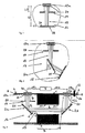
- FIG. 1 shows a sectional view of an ultrasonic measuring arrangement with a calibration reflex wall according to the invention and a surface to be examined;
- Fig. 2 an embodiment of the invention
- FIG. 3 shows a further embodiment of the invention with an ultrasonic measuring tube for flow measurement.
- FIG. 1 shows an ultrasound head 12a to which a calibration reflex wall 17 is arranged at a distance L / 2 and a surface 18 to be examined is arranged at a distance 1/2. Both the calibration reflex wall 17 and the surface 18 to be examined have a geometric change layer 20 with a thickness d. An ultrasonic signal 19 emitted from the ultrasonic head 12a is reflected by the calibration reflex wall 17 and the surface 18 and sent back to the ultrasonic transducer 12a.
- the lengths L / 2 and 1/2 between ultrasound head 12a and the elk reflex wall 17 or the surface 18 to be examined are determined and stored with high precision (for example by means of sound measurement at a precisely known speed of sound).
- the values for k and m must be determined for the respective measuring arrangement (geometry, geometric degree of change of the different reflection sites empirically) and stored.
- FIG. 3 shows a further embodiment variant of the invention with reference to an application in an ultrasonic flow measurement.
- Fig. 3 shows an ultrasonic flow meter 1, the z. B. is used as a water or heat meter in households use.
- industrial uses eg. B. for flow measurement of other liquid or gaseous media, in particular chemical liquids or gases possible.
- the ultrasonic flowmeter 1 is hereinafter referred to as flowmeter 1.
- the flow meter 1 initially comprises a measuring tube 3, which is interposed in a not shown in detail line of a supply system, such as a domestic water supply. It has end-side connecting flanges 5, which are provided on the outside with threads 6.
- the measuring tube 3 has on the inside over the region B a narrowing of its inner cross section.
- the ultrasonic heads 12a and 12b may be generally configured in the prior art.
- the ultrasonic heads 12a and 12b are preferably designed as so-called pot converters with a metal housing, in particular of brass material.
- Such ultrasonic heads are for example from the EP 0 679 874 and the EP 0 858 844 A2 known.
- the flanges with the associated ultrasonic heads 12a and 12b are attached to the measuring tube 1 in such a way that the ultrasonic heads 12a and 12b project into the interior of the measuring tube 1 perpendicular to the direction of flow of the medium.
- the ultrasonic heads 12a and 12b are connected to a processing device 7 via their respective connection lugs 4a and 4b and lines 15a, 15b.
- the processing device 7 serves to control the ultrasound heads 12a, 12b and to evaluate their received signals.
- a temperature sensor 13 which is also connected to the processing device 7 via a line 15c and protrudes with its sensor end 14 into the measuring tube 3 and thus into the medium flow.
- the ultrasonic signal is sent from one of the ultrasonic heads 12a, 12b to the other and vice versa. From the transit time difference of the signals - with and against the medium flow - the FIieBieri is determined in the processing device 7. Taking into account the cross section of the measuring section 8, the flow rate can then be calculated. In order to guide the ultrasonic signal from the ultrasonic heads 12a, 12b longitudinally through the measuring section 8, it is deflected via deflecting mirrors 2a and 2b.
Landscapes
- Physics & Mathematics (AREA)
- Fluid Mechanics (AREA)
- General Physics & Mathematics (AREA)
- Electromagnetism (AREA)
- Length Measuring Devices Characterised By Use Of Acoustic Means (AREA)
- Measurement Of Velocity Or Position Using Acoustic Or Ultrasonic Waves (AREA)
- Ultra Sonic Daignosis Equipment (AREA)
Priority Applications (4)
| Application Number | Priority Date | Filing Date | Title |
|---|---|---|---|
| DE502005007846T DE502005007846D1 (de) | 2005-06-10 | 2005-06-10 | Schichtdickenmessverfahren für einen Ultraschalldurchflussmesskanal |
| AT05012518T ATE438841T1 (de) | 2005-06-10 | 2005-06-10 | Schichtdickenmessverfahren für einen ultraschalldurchflussmesskanal |
| DK05012518T DK1731884T3 (da) | 2005-06-10 | 2005-06-10 | Målemetode for en ultralydmålekanal |
| EP05012518A EP1731884B1 (fr) | 2005-06-10 | 2005-06-10 | Procédé de mesure de l'epaisseur d'une couche d'un canal de mesure de débit par ultrasons |
Applications Claiming Priority (1)
| Application Number | Priority Date | Filing Date | Title |
|---|---|---|---|
| EP05012518A EP1731884B1 (fr) | 2005-06-10 | 2005-06-10 | Procédé de mesure de l'epaisseur d'une couche d'un canal de mesure de débit par ultrasons |
Publications (2)
| Publication Number | Publication Date |
|---|---|
| EP1731884A1 true EP1731884A1 (fr) | 2006-12-13 |
| EP1731884B1 EP1731884B1 (fr) | 2009-08-05 |
Family
ID=35456910
Family Applications (1)
| Application Number | Title | Priority Date | Filing Date |
|---|---|---|---|
| EP05012518A Active EP1731884B1 (fr) | 2005-06-10 | 2005-06-10 | Procédé de mesure de l'epaisseur d'une couche d'un canal de mesure de débit par ultrasons |
Country Status (4)
| Country | Link |
|---|---|
| EP (1) | EP1731884B1 (fr) |
| AT (1) | ATE438841T1 (fr) |
| DE (1) | DE502005007846D1 (fr) |
| DK (1) | DK1731884T3 (fr) |
Cited By (2)
| Publication number | Priority date | Publication date | Assignee | Title |
|---|---|---|---|---|
| US7819021B2 (en) | 2007-03-09 | 2010-10-26 | Hydrometer Gmbh | Fluid meter |
| CN116499539A (zh) * | 2023-03-15 | 2023-07-28 | 杭州山科智能科技股份有限公司 | 一种超声水表及测量方法 |
Citations (4)
| Publication number | Priority date | Publication date | Assignee | Title |
|---|---|---|---|---|
| EP0437872A2 (fr) * | 1989-12-14 | 1991-07-24 | Anadrill International SA | Procédé et système pour la mesure du débit dans une conduite de retour d'un puits |
| DE4027030A1 (de) * | 1990-08-27 | 1992-03-05 | Honeywell Regelsysteme Gmbh | Verfahren und vorrichtung zur messung der stroemungsgeschwindigkeit |
| EP0773431A2 (fr) | 1995-11-13 | 1997-05-14 | Siemens Aktiengesellschaft | Débitmètre ultrasonique pour des milieux liquides ou gazeux |
| US6381549B1 (en) | 1999-01-28 | 2002-04-30 | Dolphin Technology, Inc. | System and method using digital filters and neural networks to determine fluid flow |
-
2005
- 2005-06-10 AT AT05012518T patent/ATE438841T1/de not_active IP Right Cessation
- 2005-06-10 DK DK05012518T patent/DK1731884T3/da active
- 2005-06-10 EP EP05012518A patent/EP1731884B1/fr active Active
- 2005-06-10 DE DE502005007846T patent/DE502005007846D1/de active Active
Patent Citations (4)
| Publication number | Priority date | Publication date | Assignee | Title |
|---|---|---|---|---|
| EP0437872A2 (fr) * | 1989-12-14 | 1991-07-24 | Anadrill International SA | Procédé et système pour la mesure du débit dans une conduite de retour d'un puits |
| DE4027030A1 (de) * | 1990-08-27 | 1992-03-05 | Honeywell Regelsysteme Gmbh | Verfahren und vorrichtung zur messung der stroemungsgeschwindigkeit |
| EP0773431A2 (fr) | 1995-11-13 | 1997-05-14 | Siemens Aktiengesellschaft | Débitmètre ultrasonique pour des milieux liquides ou gazeux |
| US6381549B1 (en) | 1999-01-28 | 2002-04-30 | Dolphin Technology, Inc. | System and method using digital filters and neural networks to determine fluid flow |
Cited By (3)
| Publication number | Priority date | Publication date | Assignee | Title |
|---|---|---|---|---|
| US7819021B2 (en) | 2007-03-09 | 2010-10-26 | Hydrometer Gmbh | Fluid meter |
| CN116499539A (zh) * | 2023-03-15 | 2023-07-28 | 杭州山科智能科技股份有限公司 | 一种超声水表及测量方法 |
| CN116499539B (zh) * | 2023-03-15 | 2024-01-19 | 杭州山科智能科技股份有限公司 | 一种超声水表及测量方法 |
Also Published As
| Publication number | Publication date |
|---|---|
| ATE438841T1 (de) | 2009-08-15 |
| DK1731884T3 (da) | 2009-11-02 |
| EP1731884B1 (fr) | 2009-08-05 |
| DE502005007846D1 (de) | 2009-09-17 |
Similar Documents
| Publication | Publication Date | Title |
|---|---|---|
| EP1554549B1 (fr) | Débitmètre | |
| EP1993742B1 (fr) | Dispositif pour déterminer et/ou surveiller le débit volumique ou massique d'une substance dans une conduite tubulaire | |
| EP1337810B1 (fr) | Debitmetre par ultrasons | |
| EP3404372B1 (fr) | Débitmètre ultrasonique | |
| DE102019110514B4 (de) | Fluidmesseinrichtung | |
| DE102014004747B4 (de) | Ultraschall-Durchflussmesser | |
| WO2014191136A1 (fr) | Dispositif pour déterminer et/ou surveiller le débit volumique et/ou massique d'un fluide | |
| EP1955019B1 (fr) | Dispositif de mesure à ultrasons pour déterminer et/ou surveiller l'écoulement volumique ou massique d'une substance dans une conduite tubulaire | |
| EP3940346B1 (fr) | Débitmètre et procédé de mesure du débit d'un fluide | |
| EP1608939B1 (fr) | Dispositif permettant de determiner et/ou de surveiller le debit volumetrique et/ou massique d'un milieu | |
| DE102008013224A1 (de) | Messsystem und Verfahren zur Bestimmung und/oder Überwachung eines Durchflusses eines Messmediums durch ein Messrohr | |
| EP1701140B1 (fr) | Canal de mesure ultrasonique | |
| DE10335665B4 (de) | Massendurchflussmessgerät | |
| WO2014026723A1 (fr) | Appareil de mesure d'écoulement à vortex | |
| DE102007062913A1 (de) | Ultraschallwandler zur Bestimmung und/oder Überwachung eines Durchflusses eines Messmediums durch ein Messrohr | |
| EP1731884B1 (fr) | Procédé de mesure de l'epaisseur d'une couche d'un canal de mesure de débit par ultrasons | |
| DE19535848C1 (de) | Vorrichtung zur Messung der akustischen Impedanz von flüssigen Medien | |
| DE19503714A1 (de) | Anordnung zur Bestimmung der Strömungsgeschwindigkeit eines Fluides in Rohren mit kreisförmigem Querschnitt mittels Ultraschall | |
| DE102007053105A1 (de) | Verfahren und Vorrichtung zur Volumenstrommessung von Fluiden in Rohrleitungen | |
| DE19648784C2 (de) | Ultraschall-Durchflußmesser | |
| WO2018015218A1 (fr) | Procédé et ensemble de mesure de débit par ultrasons de manière serrée sur le tube et corps permettant de réaliser la mesure | |
| DE102013103518A1 (de) | Vorgefertigtes In-Line Messgerät | |
| DE19633558C2 (de) | Ultraschall-Durchflußmeßverfahren | |
| EP1731883B1 (fr) | Procédé pour détecter un changement géométrique d'un canal de mesure de débit par ultrasons | |
| EP3748308A1 (fr) | Débitmètre à ultrasons, utilisation d'un débitmètre à ultrasons dans un organe d'arrêt et organe d'arrêt |
Legal Events
| Date | Code | Title | Description |
|---|---|---|---|
| PUAI | Public reference made under article 153(3) epc to a published international application that has entered the european phase |
Free format text: ORIGINAL CODE: 0009012 |
|
| AK | Designated contracting states |
Kind code of ref document: A1 Designated state(s): AT BE BG CH CY CZ DE DK EE ES FI FR GB GR HU IE IS IT LI LT LU MC NL PL PT RO SE SI SK TR |
|
| AX | Request for extension of the european patent |
Extension state: AL BA HR LV MK YU |
|
| 17P | Request for examination filed |
Effective date: 20070511 |
|
| AKX | Designation fees paid |
Designated state(s): AT BE BG CH CY CZ DE DK EE ES FI FR GB GR HU IE IS IT LI LT LU MC NL PL PT RO SE SI SK TR |
|
| 17Q | First examination report despatched |
Effective date: 20080709 |
|
| RIN1 | Information on inventor provided before grant (corrected) |
Inventor name: GRUENLEITNER, JOHANN Inventor name: ROTHER, STEPHAN DR. RER. NAT. Inventor name: GAERTNER, FRANZ-GEORG Inventor name: REISSINGER, ACHIM |
|
| GRAP | Despatch of communication of intention to grant a patent |
Free format text: ORIGINAL CODE: EPIDOSNIGR1 |
|
| GRAS | Grant fee paid |
Free format text: ORIGINAL CODE: EPIDOSNIGR3 |
|
| GRAA | (expected) grant |
Free format text: ORIGINAL CODE: 0009210 |
|
| AK | Designated contracting states |
Kind code of ref document: B1 Designated state(s): AT BE BG CH CY CZ DE DK EE ES FI FR GB GR HU IE IS IT LI LT LU MC NL PL PT RO SE SI SK TR |
|
| REG | Reference to a national code |
Ref country code: GB Ref legal event code: FG4D Free format text: NOT ENGLISH |
|
| REG | Reference to a national code |
Ref country code: CH Ref legal event code: EP |
|
| REG | Reference to a national code |
Ref country code: IE Ref legal event code: FG4D |
|
| REF | Corresponds to: |
Ref document number: 502005007846 Country of ref document: DE Date of ref document: 20090917 Kind code of ref document: P |
|
| REG | Reference to a national code |
Ref country code: DK Ref legal event code: T3 |
|
| LTIE | Lt: invalidation of european patent or patent extension |
Effective date: 20090805 |
|
| PG25 | Lapsed in a contracting state [announced via postgrant information from national office to epo] |
Ref country code: LT Free format text: LAPSE BECAUSE OF FAILURE TO SUBMIT A TRANSLATION OF THE DESCRIPTION OR TO PAY THE FEE WITHIN THE PRESCRIBED TIME-LIMIT Effective date: 20090805 Ref country code: FI Free format text: LAPSE BECAUSE OF FAILURE TO SUBMIT A TRANSLATION OF THE DESCRIPTION OR TO PAY THE FEE WITHIN THE PRESCRIBED TIME-LIMIT Effective date: 20090805 Ref country code: ES Free format text: LAPSE BECAUSE OF FAILURE TO SUBMIT A TRANSLATION OF THE DESCRIPTION OR TO PAY THE FEE WITHIN THE PRESCRIBED TIME-LIMIT Effective date: 20091116 Ref country code: SE Free format text: LAPSE BECAUSE OF FAILURE TO SUBMIT A TRANSLATION OF THE DESCRIPTION OR TO PAY THE FEE WITHIN THE PRESCRIBED TIME-LIMIT Effective date: 20090805 Ref country code: IS Free format text: LAPSE BECAUSE OF FAILURE TO SUBMIT A TRANSLATION OF THE DESCRIPTION OR TO PAY THE FEE WITHIN THE PRESCRIBED TIME-LIMIT Effective date: 20091205 |
|
| NLV1 | Nl: lapsed or annulled due to failure to fulfill the requirements of art. 29p and 29m of the patents act | ||
| PG25 | Lapsed in a contracting state [announced via postgrant information from national office to epo] |
Ref country code: SI Free format text: LAPSE BECAUSE OF FAILURE TO SUBMIT A TRANSLATION OF THE DESCRIPTION OR TO PAY THE FEE WITHIN THE PRESCRIBED TIME-LIMIT Effective date: 20090805 Ref country code: NL Free format text: LAPSE BECAUSE OF FAILURE TO SUBMIT A TRANSLATION OF THE DESCRIPTION OR TO PAY THE FEE WITHIN THE PRESCRIBED TIME-LIMIT Effective date: 20090805 Ref country code: PL Free format text: LAPSE BECAUSE OF FAILURE TO SUBMIT A TRANSLATION OF THE DESCRIPTION OR TO PAY THE FEE WITHIN THE PRESCRIBED TIME-LIMIT Effective date: 20090805 |
|
| REG | Reference to a national code |
Ref country code: IE Ref legal event code: FD4D |
|
| PG25 | Lapsed in a contracting state [announced via postgrant information from national office to epo] |
Ref country code: BG Free format text: LAPSE BECAUSE OF FAILURE TO SUBMIT A TRANSLATION OF THE DESCRIPTION OR TO PAY THE FEE WITHIN THE PRESCRIBED TIME-LIMIT Effective date: 20091105 Ref country code: PT Free format text: LAPSE BECAUSE OF FAILURE TO SUBMIT A TRANSLATION OF THE DESCRIPTION OR TO PAY THE FEE WITHIN THE PRESCRIBED TIME-LIMIT Effective date: 20091205 |
|
| PG25 | Lapsed in a contracting state [announced via postgrant information from national office to epo] |
Ref country code: RO Free format text: LAPSE BECAUSE OF FAILURE TO SUBMIT A TRANSLATION OF THE DESCRIPTION OR TO PAY THE FEE WITHIN THE PRESCRIBED TIME-LIMIT Effective date: 20090805 Ref country code: CZ Free format text: LAPSE BECAUSE OF FAILURE TO SUBMIT A TRANSLATION OF THE DESCRIPTION OR TO PAY THE FEE WITHIN THE PRESCRIBED TIME-LIMIT Effective date: 20090805 Ref country code: IE Free format text: LAPSE BECAUSE OF FAILURE TO SUBMIT A TRANSLATION OF THE DESCRIPTION OR TO PAY THE FEE WITHIN THE PRESCRIBED TIME-LIMIT Effective date: 20090805 Ref country code: EE Free format text: LAPSE BECAUSE OF FAILURE TO SUBMIT A TRANSLATION OF THE DESCRIPTION OR TO PAY THE FEE WITHIN THE PRESCRIBED TIME-LIMIT Effective date: 20090805 |
|
| PG25 | Lapsed in a contracting state [announced via postgrant information from national office to epo] |
Ref country code: SK Free format text: LAPSE BECAUSE OF FAILURE TO SUBMIT A TRANSLATION OF THE DESCRIPTION OR TO PAY THE FEE WITHIN THE PRESCRIBED TIME-LIMIT Effective date: 20090805 |
|
| PLBE | No opposition filed within time limit |
Free format text: ORIGINAL CODE: 0009261 |
|
| STAA | Information on the status of an ep patent application or granted ep patent |
Free format text: STATUS: NO OPPOSITION FILED WITHIN TIME LIMIT |
|
| 26N | No opposition filed |
Effective date: 20100507 |
|
| PG25 | Lapsed in a contracting state [announced via postgrant information from national office to epo] |
Ref country code: GR Free format text: LAPSE BECAUSE OF FAILURE TO SUBMIT A TRANSLATION OF THE DESCRIPTION OR TO PAY THE FEE WITHIN THE PRESCRIBED TIME-LIMIT Effective date: 20091106 |
|
| BERE | Be: lapsed |
Owner name: LANDIS+GYR G.M.B.H. Effective date: 20100630 |
|
| PG25 | Lapsed in a contracting state [announced via postgrant information from national office to epo] |
Ref country code: MC Free format text: LAPSE BECAUSE OF NON-PAYMENT OF DUE FEES Effective date: 20100630 |
|
| REG | Reference to a national code |
Ref country code: CH Ref legal event code: PL |
|
| GBPC | Gb: european patent ceased through non-payment of renewal fee |
Effective date: 20100610 |
|
| REG | Reference to a national code |
Ref country code: FR Ref legal event code: ST Effective date: 20110228 |
|
| PG25 | Lapsed in a contracting state [announced via postgrant information from national office to epo] |
Ref country code: IT Free format text: LAPSE BECAUSE OF FAILURE TO SUBMIT A TRANSLATION OF THE DESCRIPTION OR TO PAY THE FEE WITHIN THE PRESCRIBED TIME-LIMIT Effective date: 20090805 |
|
| PG25 | Lapsed in a contracting state [announced via postgrant information from national office to epo] |
Ref country code: LI Free format text: LAPSE BECAUSE OF NON-PAYMENT OF DUE FEES Effective date: 20100630 Ref country code: CH Free format text: LAPSE BECAUSE OF NON-PAYMENT OF DUE FEES Effective date: 20100630 |
|
| PG25 | Lapsed in a contracting state [announced via postgrant information from national office to epo] |
Ref country code: FR Free format text: LAPSE BECAUSE OF NON-PAYMENT OF DUE FEES Effective date: 20100630 |
|
| PG25 | Lapsed in a contracting state [announced via postgrant information from national office to epo] |
Ref country code: BE Free format text: LAPSE BECAUSE OF NON-PAYMENT OF DUE FEES Effective date: 20100630 |
|
| PG25 | Lapsed in a contracting state [announced via postgrant information from national office to epo] |
Ref country code: GB Free format text: LAPSE BECAUSE OF NON-PAYMENT OF DUE FEES Effective date: 20100610 |
|
| PG25 | Lapsed in a contracting state [announced via postgrant information from national office to epo] |
Ref country code: AT Free format text: LAPSE BECAUSE OF NON-PAYMENT OF DUE FEES Effective date: 20100610 |
|
| PG25 | Lapsed in a contracting state [announced via postgrant information from national office to epo] |
Ref country code: CY Free format text: LAPSE BECAUSE OF FAILURE TO SUBMIT A TRANSLATION OF THE DESCRIPTION OR TO PAY THE FEE WITHIN THE PRESCRIBED TIME-LIMIT Effective date: 20090805 |
|
| PG25 | Lapsed in a contracting state [announced via postgrant information from national office to epo] |
Ref country code: HU Free format text: LAPSE BECAUSE OF FAILURE TO SUBMIT A TRANSLATION OF THE DESCRIPTION OR TO PAY THE FEE WITHIN THE PRESCRIBED TIME-LIMIT Effective date: 20100206 Ref country code: LU Free format text: LAPSE BECAUSE OF NON-PAYMENT OF DUE FEES Effective date: 20100610 |
|
| PG25 | Lapsed in a contracting state [announced via postgrant information from national office to epo] |
Ref country code: TR Free format text: LAPSE BECAUSE OF FAILURE TO SUBMIT A TRANSLATION OF THE DESCRIPTION OR TO PAY THE FEE WITHIN THE PRESCRIBED TIME-LIMIT Effective date: 20090805 |
|
| REG | Reference to a national code |
Ref country code: DE Ref legal event code: R082 Ref document number: 502005007846 Country of ref document: DE Representative=s name: PROCK, THOMAS, DR., GB Ref country code: DE Ref legal event code: R082 Ref document number: 502005007846 Country of ref document: DE |
|
| REG | Reference to a national code |
Ref country code: DE Ref legal event code: R082 Ref document number: 502005007846 Country of ref document: DE Representative=s name: PROCK, THOMAS, DR., GB |
|
| P01 | Opt-out of the competence of the unified patent court (upc) registered |
Effective date: 20230517 |
|
| PGFP | Annual fee paid to national office [announced via postgrant information from national office to epo] |
Ref country code: DK Payment date: 20230622 Year of fee payment: 19 Ref country code: DE Payment date: 20230620 Year of fee payment: 19 |