EP1731884A1 - Schichtdickenmessverfahren für einen Ultraschalldurchflussmesskanal - Google Patents
Schichtdickenmessverfahren für einen Ultraschalldurchflussmesskanal Download PDFInfo
- Publication number
- EP1731884A1 EP1731884A1 EP05012518A EP05012518A EP1731884A1 EP 1731884 A1 EP1731884 A1 EP 1731884A1 EP 05012518 A EP05012518 A EP 05012518A EP 05012518 A EP05012518 A EP 05012518A EP 1731884 A1 EP1731884 A1 EP 1731884A1
- Authority
- EP
- European Patent Office
- Prior art keywords
- ultrasonic
- ultrasonic transducer
- measuring
- ultrasound
- transducer
- Prior art date
- Legal status (The legal status is an assumption and is not a legal conclusion. Google has not performed a legal analysis and makes no representation as to the accuracy of the status listed.)
- Granted
Links
Images
Classifications
-
- G—PHYSICS
- G01—MEASURING; TESTING
- G01F—MEASURING VOLUME, VOLUME FLOW, MASS FLOW OR LIQUID LEVEL; METERING BY VOLUME
- G01F1/00—Measuring the volume flow or mass flow of fluid or fluent solid material wherein the fluid passes through a meter in a continuous flow
- G01F1/66—Measuring the volume flow or mass flow of fluid or fluent solid material wherein the fluid passes through a meter in a continuous flow by measuring frequency, phase shift or propagation time of electromagnetic or other waves, e.g. using ultrasonic flowmeters
- G01F1/662—Constructional details
-
- G—PHYSICS
- G01—MEASURING; TESTING
- G01F—MEASURING VOLUME, VOLUME FLOW, MASS FLOW OR LIQUID LEVEL; METERING BY VOLUME
- G01F25/00—Testing or calibration of apparatus for measuring volume, volume flow or liquid level or for metering by volume
- G01F25/10—Testing or calibration of apparatus for measuring volume, volume flow or liquid level or for metering by volume of flowmeters
Definitions
- the invention relates to a measuring method for an ultrasonic measuring channel for determining a thickness of a geometric change on ultrasound reflecting surfaces arranged within an ultrasound measuring path. Furthermore, the invention relates to a measuring arrangement for carrying out the measuring method.
- the flowing medium is detected integrating taking into account its flow behavior, d. H.
- the flow rate of the volumetric flow which is variable over the entire cross section of the measuring channel, is summarily detected by a suitable measuring structure and averaged (integral mean value).
- This "integrating detection of the total volume flow” is currently achieved via the most complete possible detection of the sound emitted from the ultrasonic transmitter sound field by utilizing the reflection properties at boundary layers or on the generation of nearly flat waves and absorption of all disturbing wave trains.
- a well-known phenomenon in ultrasonic flow measurement is that ultrasound pulses emitted "keulenförmig" from a first ultrasonic transducer are detected by a second, receiving ultrasonic transducer as an overlay of a direct beam and at least one reflection beam.
- the direct beam is that portion of the receiving ultrasonic wave signal which arrives directly through the applied flow medium at the second ultrasonic transducer.
- the portion of the received ultrasonic wave signal which is reflected at the wall of the flowed through measurement channel, sets a compared to the direct jet increased trajectory back and thus meets with a time lag or phase-shifted in the second ultrasonic transducer.
- the invention has the object of developing a measuring method and a measuring arrangement for an ultrasonic measuring channel of the aforementioned type such that even with a change in geometry of an ultrasonic measuring channel in the flowing medium an accurate measurement is possible.
- the core of the present invention can be seen in the fact that by means of an ultrasonic signal which impinges on a calibration reflex wall and on a surface to be examined, a thickness of a geometric change can be determined by simply measuring the transit times of the ultrasonic signal to the calibration reflex wall and to the surface to be examined, taking into account geometric proportionality factors. Once this thickness of the geometric change has been determined, it can be taken into account with advantage over conventional measuring methods in a flow measurement according to the entrainment principle by ultrasound, so that the influence of the geometry change can be eliminated.
- geometric change means any change on walls of an ultrasonic measuring channel, such as, for example, contamination or erosion.
- FIG. 1 shows a sectional view of an ultrasonic measuring arrangement with a calibration reflex wall according to the invention and a surface to be examined;
- Fig. 2 an embodiment of the invention
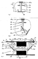
- FIG. 3 shows a further embodiment of the invention with an ultrasonic measuring tube for flow measurement.
- FIG. 1 shows an ultrasound head 12a to which a calibration reflex wall 17 is arranged at a distance L / 2 and a surface 18 to be examined is arranged at a distance 1/2. Both the calibration reflex wall 17 and the surface 18 to be examined have a geometric change layer 20 with a thickness d. An ultrasonic signal 19 emitted from the ultrasonic head 12a is reflected by the calibration reflex wall 17 and the surface 18 and sent back to the ultrasonic transducer 12a.
- the lengths L / 2 and 1/2 between ultrasound head 12a and the elk reflex wall 17 or the surface 18 to be examined are determined and stored with high precision (for example by means of sound measurement at a precisely known speed of sound).
- the values for k and m must be determined for the respective measuring arrangement (geometry, geometric degree of change of the different reflection sites empirically) and stored.
- FIG. 3 shows a further embodiment variant of the invention with reference to an application in an ultrasonic flow measurement.
- Fig. 3 shows an ultrasonic flow meter 1, the z. B. is used as a water or heat meter in households use.
- industrial uses eg. B. for flow measurement of other liquid or gaseous media, in particular chemical liquids or gases possible.
- the ultrasonic flowmeter 1 is hereinafter referred to as flowmeter 1.
- the flow meter 1 initially comprises a measuring tube 3, which is interposed in a not shown in detail line of a supply system, such as a domestic water supply. It has end-side connecting flanges 5, which are provided on the outside with threads 6.
- the measuring tube 3 has on the inside over the region B a narrowing of its inner cross section.
- the ultrasonic heads 12a and 12b may be generally configured in the prior art.
- the ultrasonic heads 12a and 12b are preferably designed as so-called pot converters with a metal housing, in particular of brass material.
- Such ultrasonic heads are for example from the EP 0 679 874 and the EP 0 858 844 A2 known.
- the flanges with the associated ultrasonic heads 12a and 12b are attached to the measuring tube 1 in such a way that the ultrasonic heads 12a and 12b project into the interior of the measuring tube 1 perpendicular to the direction of flow of the medium.
- the ultrasonic heads 12a and 12b are connected to a processing device 7 via their respective connection lugs 4a and 4b and lines 15a, 15b.
- the processing device 7 serves to control the ultrasound heads 12a, 12b and to evaluate their received signals.
- a temperature sensor 13 which is also connected to the processing device 7 via a line 15c and protrudes with its sensor end 14 into the measuring tube 3 and thus into the medium flow.
- the ultrasonic signal is sent from one of the ultrasonic heads 12a, 12b to the other and vice versa. From the transit time difference of the signals - with and against the medium flow - the FIieBieri is determined in the processing device 7. Taking into account the cross section of the measuring section 8, the flow rate can then be calculated. In order to guide the ultrasonic signal from the ultrasonic heads 12a, 12b longitudinally through the measuring section 8, it is deflected via deflecting mirrors 2a and 2b.
Landscapes
- Physics & Mathematics (AREA)
- Fluid Mechanics (AREA)
- General Physics & Mathematics (AREA)
- Electromagnetism (AREA)
- Length Measuring Devices Characterised By Use Of Acoustic Means (AREA)
- Measurement Of Velocity Or Position Using Acoustic Or Ultrasonic Waves (AREA)
- Ultra Sonic Daignosis Equipment (AREA)
Abstract
Description
- Die Erfindung bezieht sich auf ein Messverfahren für einen Ultraschallmesskanal zur Bestimmung einer Dicke einer geometrischen Veränderung auf innerhalb eines Ultraschallmessweges angeordneten, Ultraschall reflektierenden Flächen. Des Weiteren bezieht sich die Erfindung auf eine Messanordnung zur Durchführung des Messverfahrens.
- Stand der Technik
- Allen bekannten Messverfahren für Ultraschallmesskanäle liegt die gemeinsame Aufgabe zugrunde, dass möglichst verlustfrei hochfrequente akustische Signale, vorzugsweise Ultraschallsignale, in ein zu untersuchendes Medium eingekoppelt werden, um zumeist nach dem Prinzip der Laufzeitdifferenzmessung (Mitnahmeeffekt) die Laufzeit von innerhalb des Mediums reflektierten Ultraschallwellen zu erfassen. Aus der Laufzeitdifferenz der mit dem bzw. gegen das Medium ausgesandten Ultraschallsignale kann dann die Fliessgeschwindigkeit des Mediums selbst ermittelt werden.
- Im Messkanal einer Ultraschallmessanordnung wird das durchfliessende Medium unter Berücksichtigung seines Strömungsverhaltens integrierend erfasst, d. h. die über den gesamten Querschnitt des Messkanals variable Strömungsgeschwindigkeit des Volumenstroms wird durch einen geeigneten Messaufbau summarisch erfasst und gemittelt (Integralmittelwert).
- Diese "integrierende Erfassung des gesamten Volumenstroms" wird gegenwärtig über die möglichst vollständige Erfassung des vom Ultraschallsender abgegebenen Schallfeldes unter Ausnutzung der Reflexionseigenschaften an Grenzschichten oder über die Erzeugung nahezu ebener Wellen und Absorption aller störenden Wellenzüge erreicht.
- Die Messung mittels Ultraschall geniesst wegen ihrer Genauigkeit und der geringen Messdauer eine besondere Stellung im Bereich der Durchflussmessverfahren, zu denen beispielsweise auch die Durchflussmessung nach dem Flügelradprinzip gehört. Ein bekanntes Phänomen bei der Ultraschalldurchflussmessung ist, dass von einem ersten Ultraschallwandler "keulenförmlg" ausgesandte Ultraschallimpulse bei einem zweiten, empfangenden Ultraschallwandler als eine Überlagerung aus einem Direktstrahl und mindestens einem Reflektionsstrahl erfasst wird. Der Direktstrahl ist derjenige Anteil des empfangenden Ultraschallwellensignals, der unmittelbar durch das beaufschlagte Strömungsmedium beim zweiten Ultraschallwandler eintrifft. Derjenige Anteil des empfangenen Ultraschallwellensignals, der an der Wandung des durchströmten Messkanals reflektiert wird, legt einen gegenüber dem Direktstrahl vergrösserten Laufweg zurück und trifft demzufolge mit zeitlichem Versatz bzw. phasenverschoben bei dem zweiten Ultraschallwandler ein.
- Mit der Kenntnis, dass das empfangene Signal am zweiten Ultraschallwandler eine derartig Überlagerung darstellt, die von der Kanalgeometrie und damit einer Geometrieänderung abhängig ist, gehört diese exakte Laufzeitmessung bereits seit geraumer Zeit zum Stand der Technik.
- Da üblicherweise Ultraschallmessanordnungen unter Berücksichtigung zweier turnusmässiger Funktionsüberprüfungen bis zu 15 Jahre im Einsatz verbleiben, muss aber die Messgenauigkeit langzeitstabil gewährleistet werden.
- Hingegen hat sich gezeigt, dass nicht nur Flügelraddurchflussmesser sondern auch Ultraschalldurchflussmesser auf Geometrieänderungen durch das sie umströmende bzw. durchströmende Medium empfindlich reagieren können.
- Diese geometrischen Änderungsphänomene können ohne weiteres während der Einsatzdauer eines Durchflussmessers einen signifikanten Einfluss gewinnen. Dieser Einfluss der Geometrieänderung ist dann insbesondere spürbar für diejenigen Anteile eines empfangenen Ultraschallwellensignals, die mit den geometrisch veränderten Wandungen in Kontakt treten, nämlich der Refilektionsstrahl -wie bereits oben angesprochen. Die Laufzeit dieses Reflektionsstrahls verändert sich dann aufgrund der geometrischen Laufwegänderung.
- Darstellung der Erfindung
- Der Erfindung liegt die Aufgabe zugrunde, ein Messverfahren und eine Messanordnung für einen Ultraschallmesskanal der vorstehend genannten Gattung derart weiterzubilden, dass selbst bei einer Geometrieänderung eines Ultraschallmesskanals im strömenden Medium eine genaue Messung ermöglicht wird.
- Die Lösung der der Erfindung zugrunde liegenden Aufgabe ist für das Messverfahren im Anspruch 1 und für die Messanordnung im Anspruch 3 angegeben. Den Erfindungsgedanken vorteilhaft weiterbildende Merkmale für das Messverfahren ist Gegenstand des Unteranspruchs 2.
- Der Kern der vorliegenden Erfindung ist darin zu sehen, dass mittels eines Ultraschallsignals, welches auf eine Eichreflexwandung und auf eine zu untersuchende Oberfläche trifft, eine Dicke einer geometrischen Veränderung bestimmbar ist, und zwar durch einfache Messung der Laufzeiten des Ultraschallsignals zu der Eichreflexwandung und zu der zu untersuchenden Oberfläche unter Berücksichtigung geometrischer Proportionalitätsfaktoren. Ist diese Dicke der geometrischen Veränderung einmal bestimmt, kann sie mit Vorteil gegenüber herkömmlichen Messverfahren bei einer Durchflussmessung nach dem Mitnahmeprinzip durch Ultraschall entsprechend berücksichtigt werden, so dass der Einfluss der Geometrieänderung eliminiert werden kann. Unter geometrischer Veränderung im Sinne der Erfindung wird jede Veränderung an Wandungen eines Ultraschallmesskanals verstanden, wie zum Beispiel eine Verschmutzung oder eine Abtragung.
- Kurze Beschreibung der Figuren
- Die Erfindung wird nachstehend ohne Beschränkung des allgemeinen Erfindungsgedankens anhand von Ausführungsbeispielen unter Bezugnahme auf die Zeichnungen exemplarisch beschrieben. Es zeigen die
- Fig. 1: eine Schnittdarstellung einer Ultraschallmessanordnung mit einer erfindungsgemässen Eichreflexwandung und einer zu untersuchenden Oberfläche;
- Fig. 2: eine Ausführungsvariante der Erfindung, und
- Fig. 3: eine weitere Ausführungsvariante der Erfindung mit einem Ultraschallmessrohr zur Durchflussmessung.
- Wege zur Ausführung der Erfindung, gewerbliche Verwendbarkeit
- Fig. 1 zeigt einen Ultraschallkopf 12a, zu dem in einem Abstand L/2 eine Eichreflexwandung 17 und in einem Abstand 1/2 eine zu untersuchende Oberfläche 18 angeordnet ist. Sowohl die Eichreflexwandung 17 als auch die zu untersuchende Oberfläche 18 weisen eine geometrische Veränderungsschicht 20 mit einer Dicke d auf. Ein von dem Ultraschallkopf 12a ausgesandtes Ultraschallsignal 19 wird von der Eichreflexwandung 17 und der Oberfläche 18 reflektiert und zurückgesendet zum Ultraschallwandler 12a.
- Im unveränderten Zustand der gesamten Messanordnung werden die Längen L/2 und 1/2 zwischen Ultraschallkopf 12a und der Elchreflexwandung 17 bzw. der zu untersuchender Oberfläche 18 hochgenau (z.B. mittels Schallmessung bei exakt bekannter Schallgeschwindigkeit) ermittelt und gespeichert.
- Bildet sich auf der zu untersuchenden Oberfläche 18 eine geometrische Veränderungsschicht der Dicke d, verändern sich die Abstände L/2 und 1/2 je nach Geometrie des Systems um ΔL bzw. Δl. Die Längenänderungen sind proportional zur Schichtdicke d, wobei entsprechende Proportionalitätsfaktoren mit k und m bezeichnet werden; somit ergibt sich für ΔL bzw. Δl:

- Die Werte für k und m müssen für die jeweilige Messanordnung ermittelt (Geometrie, geometrischer Änderungsgrad der verschiedenen Reflexionsstellen empirisch) und gespeichert werden.
- Beispiele für k und m:
- direkte Bestrahlung wie in Fig. 1 gezeigt, identische geometrische Änderung von Ultraschallkopf 12a, Eichreflexwandung 17 und zu untersuchender Oberfläche 18:

- direkte Bestrahlung, identische geometrische Änderung von Ultraschallkopf 12a und Oberfläche 18:
- Eichreflexwandung 17 verändert sich nur halb so stark (aufgrund unterschiedlichen Materials):

- Eichreflexwandung 17 verändert sich nur halb so stark (aufgrund unterschiedlichen Materials):
- direkte Bestrahlung der Eichreflexwandung, Oberfläche wird über einen Umlenkspiegel (Winkel a) bestrahlt, wie eine erste Ausführungsvariante in Fig. 2 zeigt:
- identische geometrische Änderung von Ultraschallkopf 12a, Eichreflexwandung 17 und Oberfläche 18:

- identische geometrische Änderung von Ultraschallkopf 12a, Eichreflexwandung 17 und Oberfläche 18:
- Im Zustand mit einer geometrischen Änderung werden nun die Laufzeiten T und t ermittelt, die das Schallsignal benötigt, um die Strecken L mit L=2 L/2 (Ultraschallkopf 12a - Eichreflexwandung 17 - Ultraschallkopf 12a) und I mit 1=2 1/2 (Ultraschallkopf 12a - Oberfläche 18 - Ultraschallkopf 12a) zu durchlaufen. Mit der Schallgeschwindigkeit c und den gespeicherten Werten L/2 bzw. L, 1/2 bzw. 1, m und k lässt sich die Schichtdicke d berechnen:


- Fig. 3 zeigt eine weitere Ausführungsvariante der Erfindung anhand einer Anwendung bei einer Ultraschalldurchflussmessung. Fig. 3 zeigt einen Ultraschall-Durchflussmesser 1, der z. B. als Wasser- oder Wärmemengenzähler in Haushalten Verwendung findet. Prinzipiell sind auch industrielle Verwendungen, z. B. zur Durchflussmessung von sonstigen flüssigen oder gasförmigen Medien, insbesondere chemischen Flüssigkeiten oder Gasen, möglich. Der Ultraschall-Durchflussmesser 1 wird nachfolgend mit Durchflussmesser 1 bezeichnet. Der Durchflussmesser 1 umfasst zunächst ein Messrohr 3, das in eine nicht näher gezeigte Leitung einer Versorgungsanlage, z.B. einer Hauswasserversorgung, zwischengeschaltet wird. Er weist dazu endseitige Anschlussflansche 5 auf, die außenseitig mit Gewinden 6 versehen sind. Das Messrohr 3 weist innenseitig über den Bereich B eine Verengung seines Innenquerschnitts auf. Dieser von dem Medium zu durchströmende Bereich ist als Messkanal 8 bezeichnet. An den Enden des Messkanals 8 sind in der nicht näher bezeichneten Außenwand des Messrohres 3 zueinander beabstandete Flansche angeordnet, In denen jeweils ein zugehöriger Ultraschallkopf 12a und 12b angeordnet ist. Die Ultraschallköpfe 12a und 12b können allgemein nach dem Stand der Technik ausgestaltet sein. Bevorzugt sind die Ultraschallköpfe 12a und 12b als so genannte Topfwandler mit einem Metallgehäuse, Insbesondere aus Messingwerkstoff, ausgeführt. Derartige Ultraschallköpfe (auch Schallsensoren genannt) sind beispielsweise aus der
EP 0 679 874 und derEP 0 858 844 A2 bekannt. - Die Flansche mit den dazugehörigen Ultraschallköpfen 12a bzw. 12b sind derart am Messrohr 1 befestigt, dass die Ultraschallköpfe 12a und 12b senkrecht zur Fliessrichtung des Mediums in das Innere des Messrohres 1 hineinschallen. Selbstverständlich sind die Ultraschallköpfe 12a und 12b über ihre jeweiligen Anschlussfahnen 4a und 4b und Leitungen 15a, 15b mit einer Verarbeitungseinrichtung 7 verbunden. Die Verarbeitungseinrichtung 7 dient dabei wie allgemein aus dem Stand der Technik bekannt zum Ansteuern der Ultraschallköpfe 12a, 12b und zum Auswerten ihrer Empfangssignate.
- Beim Einsatz des Durchflussmessers 1 als Wärmemengenzähler kann zusätzlich auch ein Temperatursensor 13 vorgesehen sein, der ebenfalls mit der Verarbeitungseinrichtung 7 über eine Leitung 15c verbunden ist und mit seinem Fühlerende 14 in das Messrohr 3 und somit in den Mediumsstrom hineinragt.
- Zur Messung der Durchflussmenge wird das Ultraschallsignal von einem der Ultraschallköpfe 12a, 12b zum anderen und umgekehrt gesendet. Aus dem Laufzeitunterschied der Signale - mit und gegen den Mediumsstrom - wird in der Verarbeitungseinrichtung 7 die FIieBgeschwindigkeit ermittelt. Unter Berücksichtigung des Querschnitts der Messstrecke 8 kann dann rechnerisch die Durchflussmenge ermittelt werden. Um das Ultraschallsignal von den Ultraschallköpfen 12a, 12b längs durch die Messstrecke 8 zu führen, wird es über Umlenkspiegel 2a und 2b umgelenkt.
- Wie bereits oben zu den Figuren 1 und 2 beschrieben, werden im unveränderten Zustand der gesamten Messanordnung die Längen L/2 und l/2 zwischen Ultraschallkopf 12a und der Eichreflexwandung 17 bzw. zwischen dem ersten Ultraschallwandler 12a, dem ersten und zweiten Umlenkspiegel 2a, 2b und dem zweiten Ultraschallwandler 12b hochgenau ermittelt und in der Verarbeitungseinrichtung 7 gespeichert. Im Falle einer geometrischen Veränderung (20) der Eichreflexwandung 17, der Umlenkspiegel 2a, 2b und einer Oberfläche 11 des Messrohrs 8 lässt sich die Dicke d der geometrischen Änderungsschicht nach obiger Gleichung bestimmen, wobei bei identischer Änderung aller Reflexionsstellen für die Proportionalitätsfaktoren k und m gilt:

- Die Ergebnisse aus der Dickenberechnung der geometrischen Änderungsschicht 20 finden somit unmittelbare Anwendung in dem oben beschriebenen Durchflussmessverfahren, sodass die exakte Durchflüssmessung völlig unbeeinflusst bleibt von jeder Art und der Quantität einer Geometrieänderung innerhalb des gesamten Messweges.
- 1
- Durchflussmesser
- 2a, 2b
- Umlenkspiegel
- 3
- Messrohr
- 4a, 4b
- Anschlussfahne
- 5
- Anschlussflansch
- 6
- Gewinde
- 7
- Verarbeitungseinrichtung
- 8
- Messkanal
- 11
- Oberfläche des Messkanals 8
- 12a, 12b
- Ultraschallkopf
- 13
- Temperatursensor
- 14
- Fühlerende
- 15a, 15b, 15c
- Leitung
- 16
- Medium
- 17
- Eichreflexwandung
- 18
- zu untersuchende Oberfläche
- 19
- Schallsignal
- 20
- geometrische Änderungsschicht; Geometrieänderung
Claims (3)
- Messverfahren für einen Ultraschallmesskanal (8) zur Bestimmung einer Dicke (d) einer geometrischen Änderungsschicht (20) auf innerhalb eines Ultraschallmessweges (L/2, I/2) angeordneten, Ultraschall reflektierenden Flächen (2a,2b, 11, 12a, 12b, 17, 18),
dadurch gekennzeichnet,- dass ein erstes Ultraschallsignal von einem Ultraschallwandler (12a) zu einer Eichreflexwandung (17) ausgesendet und von dieser Eichreflexwandung (17) zu dem Ultraschallwandler (12a) reflektiert wird, wobei diese Elchreflexwandung (17) in einem ersten Abstand (L/2) zu dem Ultraschallwandler (12a) angeordnet ist und wobei eine erste Laufzeit (T) des Ultraschallsignals von und zu dem Ultraschallwandler (12a) gemessen wird;- dass ein zweites Ultraschallsignal von dem Ultraschallwandler (12a) zu einer zu untersuchenden Oberfläche (2a, 2b, 11, 12a, 12b, 18) ausgesendet und von dieser Oberfläche (2a, 2b, 11, 12a, 12b, 18) zu dem Ultraschallwandler (12a) reflektiert wird, wobei diese Oberfläche (2a, 2b, 11, 12a, 12b, 18) in einem zweiten Abstand (1/2) zu dem Ultraschallwandler (12a) angeordnet ist und wobei eine zweite Laufzeit (t) des Ultraschallsignals von und zu dem Ultraschallwandler (12a) gemessen wird, und- dass sich die Schichtdicke (d) der geometrischen Änderung auf den Flächen (2a, 2b, 11, 12a, 12b, 18) ergibt zumit k als einem empirischen Geometriefaktor zur Eichreflexwandung (17) gehörig und mit m als einem empirischen Geometriefaktor zur zu untersuchenden Oberfläche (2a, 2b, 11, 12a, 12b, 18) gehörig.
- Messverfahren nach Anspruch 1,
dadurch gekennzeichnet,
dass das erste und das zweite Ultraschallsignal gleichzeitig ausgesendet wird. - Messanordnung zur Durchführung des Messverfahrens nach einem der vorhergehenden Ansprüche,
dadurch gekennzeichnet,
dass eine Eichreflexwandung (17) in einem ersten Abstand (L/2) von einem Ultraschallwandler (12a) zum Reflektieren eines von dem Ultraschallwandler (12a) aussendbaren Ultraschallsignals angeordnet ist und dass mindestens eine auf eine geometrische Änderung zu untersuchende Oberfläche (18) in einem zweiten Abstand (1/2) von dem Ultraschallwandler (12a) zum Reflektieren eines von dem Ultraschallwandler (12a) aussendbaren Ultraschallsignals angeordnet ist.
Priority Applications (4)
| Application Number | Priority Date | Filing Date | Title |
|---|---|---|---|
| AT05012518T ATE438841T1 (de) | 2005-06-10 | 2005-06-10 | Schichtdickenmessverfahren für einen ultraschalldurchflussmesskanal |
| DK05012518T DK1731884T3 (da) | 2005-06-10 | 2005-06-10 | Målemetode for en ultralydmålekanal |
| EP05012518A EP1731884B1 (de) | 2005-06-10 | 2005-06-10 | Schichtdickenmessverfahren für einen Ultraschalldurchflussmesskanal |
| DE502005007846T DE502005007846D1 (de) | 2005-06-10 | 2005-06-10 | Schichtdickenmessverfahren für einen Ultraschalldurchflussmesskanal |
Applications Claiming Priority (1)
| Application Number | Priority Date | Filing Date | Title |
|---|---|---|---|
| EP05012518A EP1731884B1 (de) | 2005-06-10 | 2005-06-10 | Schichtdickenmessverfahren für einen Ultraschalldurchflussmesskanal |
Publications (2)
| Publication Number | Publication Date |
|---|---|
| EP1731884A1 true EP1731884A1 (de) | 2006-12-13 |
| EP1731884B1 EP1731884B1 (de) | 2009-08-05 |
Family
ID=35456910
Family Applications (1)
| Application Number | Title | Priority Date | Filing Date |
|---|---|---|---|
| EP05012518A Expired - Lifetime EP1731884B1 (de) | 2005-06-10 | 2005-06-10 | Schichtdickenmessverfahren für einen Ultraschalldurchflussmesskanal |
Country Status (4)
| Country | Link |
|---|---|
| EP (1) | EP1731884B1 (de) |
| AT (1) | ATE438841T1 (de) |
| DE (1) | DE502005007846D1 (de) |
| DK (1) | DK1731884T3 (de) |
Cited By (2)
| Publication number | Priority date | Publication date | Assignee | Title |
|---|---|---|---|---|
| US7819021B2 (en) | 2007-03-09 | 2010-10-26 | Hydrometer Gmbh | Fluid meter |
| CN116499539A (zh) * | 2023-03-15 | 2023-07-28 | 杭州山科智能科技股份有限公司 | 一种超声水表及测量方法 |
Citations (4)
| Publication number | Priority date | Publication date | Assignee | Title |
|---|---|---|---|---|
| EP0437872A2 (de) * | 1989-12-14 | 1991-07-24 | Anadrill International SA | Verfahren und Vorrichtung zur Messung der Flüssigkeitsströmung in der Rücklaufleitung einer Bohranlage |
| DE4027030A1 (de) * | 1990-08-27 | 1992-03-05 | Honeywell Regelsysteme Gmbh | Verfahren und vorrichtung zur messung der stroemungsgeschwindigkeit |
| EP0773431A2 (de) | 1995-11-13 | 1997-05-14 | Siemens Aktiengesellschaft | Ultraschalldurchflussmesser für flüssige oder gasförmige Medien |
| US6381549B1 (en) | 1999-01-28 | 2002-04-30 | Dolphin Technology, Inc. | System and method using digital filters and neural networks to determine fluid flow |
-
2005
- 2005-06-10 DK DK05012518T patent/DK1731884T3/da active
- 2005-06-10 EP EP05012518A patent/EP1731884B1/de not_active Expired - Lifetime
- 2005-06-10 AT AT05012518T patent/ATE438841T1/de not_active IP Right Cessation
- 2005-06-10 DE DE502005007846T patent/DE502005007846D1/de not_active Expired - Lifetime
Patent Citations (4)
| Publication number | Priority date | Publication date | Assignee | Title |
|---|---|---|---|---|
| EP0437872A2 (de) * | 1989-12-14 | 1991-07-24 | Anadrill International SA | Verfahren und Vorrichtung zur Messung der Flüssigkeitsströmung in der Rücklaufleitung einer Bohranlage |
| DE4027030A1 (de) * | 1990-08-27 | 1992-03-05 | Honeywell Regelsysteme Gmbh | Verfahren und vorrichtung zur messung der stroemungsgeschwindigkeit |
| EP0773431A2 (de) | 1995-11-13 | 1997-05-14 | Siemens Aktiengesellschaft | Ultraschalldurchflussmesser für flüssige oder gasförmige Medien |
| US6381549B1 (en) | 1999-01-28 | 2002-04-30 | Dolphin Technology, Inc. | System and method using digital filters and neural networks to determine fluid flow |
Cited By (3)
| Publication number | Priority date | Publication date | Assignee | Title |
|---|---|---|---|---|
| US7819021B2 (en) | 2007-03-09 | 2010-10-26 | Hydrometer Gmbh | Fluid meter |
| CN116499539A (zh) * | 2023-03-15 | 2023-07-28 | 杭州山科智能科技股份有限公司 | 一种超声水表及测量方法 |
| CN116499539B (zh) * | 2023-03-15 | 2024-01-19 | 杭州山科智能科技股份有限公司 | 一种超声水表及测量方法 |
Also Published As
| Publication number | Publication date |
|---|---|
| DE502005007846D1 (de) | 2009-09-17 |
| EP1731884B1 (de) | 2009-08-05 |
| DK1731884T3 (da) | 2009-11-02 |
| ATE438841T1 (de) | 2009-08-15 |
Similar Documents
| Publication | Publication Date | Title |
|---|---|---|
| EP1554549B1 (de) | Durchflussmessgerät | |
| EP1993742B1 (de) | Vorrichtung zur bestimmung und/oder überwachung des volumen- oder des massedurchflusses eines mediums in einer rohrleitung | |
| DE10312034B3 (de) | Ultraschalldurchflußmeßverfahren | |
| EP3404372B1 (de) | Ultraschalldurchflussmessgerät | |
| EP1807680A1 (de) | Vorrichtung zur bestimmung und/oder überwachung des volumen- und/ oder massendurchflusses eines mediums | |
| EP1608939B1 (de) | Vorrichtung zur bestimmung und/oder überwachung des volumen- und/oder massenstroms eines mediums | |
| WO2014191136A1 (de) | Vorrichtung zur bestimmung und/oder überwachung des volumen- und/oder massedurchflusses eines mediums | |
| DE10335665B4 (de) | Massendurchflussmessgerät | |
| EP2871449A1 (de) | Ultraschall-Durchflussmesser | |
| DE102008013224A1 (de) | Messsystem und Verfahren zur Bestimmung und/oder Überwachung eines Durchflusses eines Messmediums durch ein Messrohr | |
| DE102007062913A1 (de) | Ultraschallwandler zur Bestimmung und/oder Überwachung eines Durchflusses eines Messmediums durch ein Messrohr | |
| EP3940346B1 (de) | Durchflussmessgerät und verfahren zur messung des durchflusses eines fluids | |
| DE202012104853U1 (de) | Durchflussmengenmesser zur Bestimmung der Durchflussmenge eines Fluids | |
| DE102007053105A1 (de) | Verfahren und Vorrichtung zur Volumenstrommessung von Fluiden in Rohrleitungen | |
| EP2883021A1 (de) | Vortex-durchflussmessgerät | |
| EP3855134B1 (de) | Vorrichtung zur messung der flussgeschwindigkeit eines fluids | |
| EP2653857B1 (de) | Trübungssensor sowie Durchflusszähler für Fluid | |
| DE202020104105U1 (de) | Durchflussmessgerät zur Messung des Durchflusses eines Fluids | |
| DE19535848C1 (de) | Vorrichtung zur Messung der akustischen Impedanz von flüssigen Medien | |
| DE19503714A1 (de) | Anordnung zur Bestimmung der Strömungsgeschwindigkeit eines Fluides in Rohren mit kreisförmigem Querschnitt mittels Ultraschall | |
| DE102013103518A1 (de) | Vorgefertigtes In-Line Messgerät | |
| EP1731884B1 (de) | Schichtdickenmessverfahren für einen Ultraschalldurchflussmesskanal | |
| EP1955019B1 (de) | Ultraschallmessvorrichtung zur bestimmung und/oder überwachung des volumen- oder massedurchflusses eines mediums durch eine rohrleitung | |
| DE19648784C2 (de) | Ultraschall-Durchflußmesser | |
| EP1701140B1 (de) | Ultraschallmesskanal |
Legal Events
| Date | Code | Title | Description |
|---|---|---|---|
| PUAI | Public reference made under article 153(3) epc to a published international application that has entered the european phase |
Free format text: ORIGINAL CODE: 0009012 |
|
| AK | Designated contracting states |
Kind code of ref document: A1 Designated state(s): AT BE BG CH CY CZ DE DK EE ES FI FR GB GR HU IE IS IT LI LT LU MC NL PL PT RO SE SI SK TR |
|
| AX | Request for extension of the european patent |
Extension state: AL BA HR LV MK YU |
|
| 17P | Request for examination filed |
Effective date: 20070511 |
|
| AKX | Designation fees paid |
Designated state(s): AT BE BG CH CY CZ DE DK EE ES FI FR GB GR HU IE IS IT LI LT LU MC NL PL PT RO SE SI SK TR |
|
| 17Q | First examination report despatched |
Effective date: 20080709 |
|
| RIN1 | Information on inventor provided before grant (corrected) |
Inventor name: GRUENLEITNER, JOHANN Inventor name: ROTHER, STEPHAN DR. RER. NAT. Inventor name: GAERTNER, FRANZ-GEORG Inventor name: REISSINGER, ACHIM |
|
| GRAP | Despatch of communication of intention to grant a patent |
Free format text: ORIGINAL CODE: EPIDOSNIGR1 |
|
| GRAS | Grant fee paid |
Free format text: ORIGINAL CODE: EPIDOSNIGR3 |
|
| GRAA | (expected) grant |
Free format text: ORIGINAL CODE: 0009210 |
|
| AK | Designated contracting states |
Kind code of ref document: B1 Designated state(s): AT BE BG CH CY CZ DE DK EE ES FI FR GB GR HU IE IS IT LI LT LU MC NL PL PT RO SE SI SK TR |
|
| REG | Reference to a national code |
Ref country code: GB Ref legal event code: FG4D Free format text: NOT ENGLISH |
|
| REG | Reference to a national code |
Ref country code: CH Ref legal event code: EP |
|
| REG | Reference to a national code |
Ref country code: IE Ref legal event code: FG4D |
|
| REF | Corresponds to: |
Ref document number: 502005007846 Country of ref document: DE Date of ref document: 20090917 Kind code of ref document: P |
|
| REG | Reference to a national code |
Ref country code: DK Ref legal event code: T3 |
|
| LTIE | Lt: invalidation of european patent or patent extension |
Effective date: 20090805 |
|
| PG25 | Lapsed in a contracting state [announced via postgrant information from national office to epo] |
Ref country code: LT Free format text: LAPSE BECAUSE OF FAILURE TO SUBMIT A TRANSLATION OF THE DESCRIPTION OR TO PAY THE FEE WITHIN THE PRESCRIBED TIME-LIMIT Effective date: 20090805 Ref country code: FI Free format text: LAPSE BECAUSE OF FAILURE TO SUBMIT A TRANSLATION OF THE DESCRIPTION OR TO PAY THE FEE WITHIN THE PRESCRIBED TIME-LIMIT Effective date: 20090805 Ref country code: ES Free format text: LAPSE BECAUSE OF FAILURE TO SUBMIT A TRANSLATION OF THE DESCRIPTION OR TO PAY THE FEE WITHIN THE PRESCRIBED TIME-LIMIT Effective date: 20091116 Ref country code: SE Free format text: LAPSE BECAUSE OF FAILURE TO SUBMIT A TRANSLATION OF THE DESCRIPTION OR TO PAY THE FEE WITHIN THE PRESCRIBED TIME-LIMIT Effective date: 20090805 Ref country code: IS Free format text: LAPSE BECAUSE OF FAILURE TO SUBMIT A TRANSLATION OF THE DESCRIPTION OR TO PAY THE FEE WITHIN THE PRESCRIBED TIME-LIMIT Effective date: 20091205 |
|
| NLV1 | Nl: lapsed or annulled due to failure to fulfill the requirements of art. 29p and 29m of the patents act | ||
| PG25 | Lapsed in a contracting state [announced via postgrant information from national office to epo] |
Ref country code: SI Free format text: LAPSE BECAUSE OF FAILURE TO SUBMIT A TRANSLATION OF THE DESCRIPTION OR TO PAY THE FEE WITHIN THE PRESCRIBED TIME-LIMIT Effective date: 20090805 Ref country code: NL Free format text: LAPSE BECAUSE OF FAILURE TO SUBMIT A TRANSLATION OF THE DESCRIPTION OR TO PAY THE FEE WITHIN THE PRESCRIBED TIME-LIMIT Effective date: 20090805 Ref country code: PL Free format text: LAPSE BECAUSE OF FAILURE TO SUBMIT A TRANSLATION OF THE DESCRIPTION OR TO PAY THE FEE WITHIN THE PRESCRIBED TIME-LIMIT Effective date: 20090805 |
|
| REG | Reference to a national code |
Ref country code: IE Ref legal event code: FD4D |
|
| PG25 | Lapsed in a contracting state [announced via postgrant information from national office to epo] |
Ref country code: BG Free format text: LAPSE BECAUSE OF FAILURE TO SUBMIT A TRANSLATION OF THE DESCRIPTION OR TO PAY THE FEE WITHIN THE PRESCRIBED TIME-LIMIT Effective date: 20091105 Ref country code: PT Free format text: LAPSE BECAUSE OF FAILURE TO SUBMIT A TRANSLATION OF THE DESCRIPTION OR TO PAY THE FEE WITHIN THE PRESCRIBED TIME-LIMIT Effective date: 20091205 |
|
| PG25 | Lapsed in a contracting state [announced via postgrant information from national office to epo] |
Ref country code: RO Free format text: LAPSE BECAUSE OF FAILURE TO SUBMIT A TRANSLATION OF THE DESCRIPTION OR TO PAY THE FEE WITHIN THE PRESCRIBED TIME-LIMIT Effective date: 20090805 Ref country code: CZ Free format text: LAPSE BECAUSE OF FAILURE TO SUBMIT A TRANSLATION OF THE DESCRIPTION OR TO PAY THE FEE WITHIN THE PRESCRIBED TIME-LIMIT Effective date: 20090805 Ref country code: IE Free format text: LAPSE BECAUSE OF FAILURE TO SUBMIT A TRANSLATION OF THE DESCRIPTION OR TO PAY THE FEE WITHIN THE PRESCRIBED TIME-LIMIT Effective date: 20090805 Ref country code: EE Free format text: LAPSE BECAUSE OF FAILURE TO SUBMIT A TRANSLATION OF THE DESCRIPTION OR TO PAY THE FEE WITHIN THE PRESCRIBED TIME-LIMIT Effective date: 20090805 |
|
| PG25 | Lapsed in a contracting state [announced via postgrant information from national office to epo] |
Ref country code: SK Free format text: LAPSE BECAUSE OF FAILURE TO SUBMIT A TRANSLATION OF THE DESCRIPTION OR TO PAY THE FEE WITHIN THE PRESCRIBED TIME-LIMIT Effective date: 20090805 |
|
| PLBE | No opposition filed within time limit |
Free format text: ORIGINAL CODE: 0009261 |
|
| STAA | Information on the status of an ep patent application or granted ep patent |
Free format text: STATUS: NO OPPOSITION FILED WITHIN TIME LIMIT |
|
| 26N | No opposition filed |
Effective date: 20100507 |
|
| PG25 | Lapsed in a contracting state [announced via postgrant information from national office to epo] |
Ref country code: GR Free format text: LAPSE BECAUSE OF FAILURE TO SUBMIT A TRANSLATION OF THE DESCRIPTION OR TO PAY THE FEE WITHIN THE PRESCRIBED TIME-LIMIT Effective date: 20091106 |
|
| BERE | Be: lapsed |
Owner name: LANDIS+GYR G.M.B.H. Effective date: 20100630 |
|
| PG25 | Lapsed in a contracting state [announced via postgrant information from national office to epo] |
Ref country code: MC Free format text: LAPSE BECAUSE OF NON-PAYMENT OF DUE FEES Effective date: 20100630 |
|
| REG | Reference to a national code |
Ref country code: CH Ref legal event code: PL |
|
| GBPC | Gb: european patent ceased through non-payment of renewal fee |
Effective date: 20100610 |
|
| REG | Reference to a national code |
Ref country code: FR Ref legal event code: ST Effective date: 20110228 |
|
| PG25 | Lapsed in a contracting state [announced via postgrant information from national office to epo] |
Ref country code: IT Free format text: LAPSE BECAUSE OF FAILURE TO SUBMIT A TRANSLATION OF THE DESCRIPTION OR TO PAY THE FEE WITHIN THE PRESCRIBED TIME-LIMIT Effective date: 20090805 |
|
| PG25 | Lapsed in a contracting state [announced via postgrant information from national office to epo] |
Ref country code: LI Free format text: LAPSE BECAUSE OF NON-PAYMENT OF DUE FEES Effective date: 20100630 Ref country code: CH Free format text: LAPSE BECAUSE OF NON-PAYMENT OF DUE FEES Effective date: 20100630 |
|
| PG25 | Lapsed in a contracting state [announced via postgrant information from national office to epo] |
Ref country code: FR Free format text: LAPSE BECAUSE OF NON-PAYMENT OF DUE FEES Effective date: 20100630 |
|
| PG25 | Lapsed in a contracting state [announced via postgrant information from national office to epo] |
Ref country code: BE Free format text: LAPSE BECAUSE OF NON-PAYMENT OF DUE FEES Effective date: 20100630 |
|
| PG25 | Lapsed in a contracting state [announced via postgrant information from national office to epo] |
Ref country code: GB Free format text: LAPSE BECAUSE OF NON-PAYMENT OF DUE FEES Effective date: 20100610 |
|
| PG25 | Lapsed in a contracting state [announced via postgrant information from national office to epo] |
Ref country code: AT Free format text: LAPSE BECAUSE OF NON-PAYMENT OF DUE FEES Effective date: 20100610 |
|
| PG25 | Lapsed in a contracting state [announced via postgrant information from national office to epo] |
Ref country code: CY Free format text: LAPSE BECAUSE OF FAILURE TO SUBMIT A TRANSLATION OF THE DESCRIPTION OR TO PAY THE FEE WITHIN THE PRESCRIBED TIME-LIMIT Effective date: 20090805 |
|
| PG25 | Lapsed in a contracting state [announced via postgrant information from national office to epo] |
Ref country code: HU Free format text: LAPSE BECAUSE OF FAILURE TO SUBMIT A TRANSLATION OF THE DESCRIPTION OR TO PAY THE FEE WITHIN THE PRESCRIBED TIME-LIMIT Effective date: 20100206 Ref country code: LU Free format text: LAPSE BECAUSE OF NON-PAYMENT OF DUE FEES Effective date: 20100610 |
|
| PG25 | Lapsed in a contracting state [announced via postgrant information from national office to epo] |
Ref country code: TR Free format text: LAPSE BECAUSE OF FAILURE TO SUBMIT A TRANSLATION OF THE DESCRIPTION OR TO PAY THE FEE WITHIN THE PRESCRIBED TIME-LIMIT Effective date: 20090805 |
|
| REG | Reference to a national code |
Ref country code: DE Ref legal event code: R082 Ref document number: 502005007846 Country of ref document: DE Representative=s name: PROCK, THOMAS, DR., GB Ref country code: DE Ref legal event code: R082 Ref document number: 502005007846 Country of ref document: DE |
|
| REG | Reference to a national code |
Ref country code: DE Ref legal event code: R082 Ref document number: 502005007846 Country of ref document: DE Representative=s name: PROCK, THOMAS, DR., GB |
|
| P01 | Opt-out of the competence of the unified patent court (upc) registered |
Effective date: 20230517 |
|
| PGFP | Annual fee paid to national office [announced via postgrant information from national office to epo] |
Ref country code: DE Payment date: 20240619 Year of fee payment: 20 |
|
| PGFP | Annual fee paid to national office [announced via postgrant information from national office to epo] |
Ref country code: DK Payment date: 20240621 Year of fee payment: 20 |
|
| REG | Reference to a national code |
Ref country code: DE Ref legal event code: R071 Ref document number: 502005007846 Country of ref document: DE |
|
| REG | Reference to a national code |
Ref country code: DK Ref legal event code: EUP Expiry date: 20250610 |