EP1731810B2 - Eingehüllte Ventilvorrichtung und zugehörige Verfahren - Google Patents
Eingehüllte Ventilvorrichtung und zugehörige Verfahren Download PDFInfo
- Publication number
- EP1731810B2 EP1731810B2 EP06253009.2A EP06253009A EP1731810B2 EP 1731810 B2 EP1731810 B2 EP 1731810B2 EP 06253009 A EP06253009 A EP 06253009A EP 1731810 B2 EP1731810 B2 EP 1731810B2
- Authority
- EP
- European Patent Office
- Prior art keywords
- shrouded
- conduit
- inner conduit
- valve member
- fuel system
- Prior art date
- Legal status (The legal status is an assumption and is not a legal conclusion. Google has not performed a legal analysis and makes no representation as to the accuracy of the status listed.)
- Active
Links
Images


Classifications
-
- F—MECHANICAL ENGINEERING; LIGHTING; HEATING; WEAPONS; BLASTING
- F16—ENGINEERING ELEMENTS AND UNITS; GENERAL MEASURES FOR PRODUCING AND MAINTAINING EFFECTIVE FUNCTIONING OF MACHINES OR INSTALLATIONS; THERMAL INSULATION IN GENERAL
- F16K—VALVES; TAPS; COCKS; ACTUATING-FLOATS; DEVICES FOR VENTING OR AERATING
- F16K1/00—Lift valves or globe valves, i.e. cut-off apparatus with closure members having at least a component of their opening and closing motion perpendicular to the closing faces
- F16K1/16—Lift valves or globe valves, i.e. cut-off apparatus with closure members having at least a component of their opening and closing motion perpendicular to the closing faces with pivoted closure-members
- F16K1/18—Lift valves or globe valves, i.e. cut-off apparatus with closure members having at least a component of their opening and closing motion perpendicular to the closing faces with pivoted closure-members with pivoted discs or flaps
- F16K1/22—Lift valves or globe valves, i.e. cut-off apparatus with closure members having at least a component of their opening and closing motion perpendicular to the closing faces with pivoted closure-members with pivoted discs or flaps with axis of rotation crossing the valve member, e.g. butterfly valves
-
- F—MECHANICAL ENGINEERING; LIGHTING; HEATING; WEAPONS; BLASTING
- F16—ENGINEERING ELEMENTS AND UNITS; GENERAL MEASURES FOR PRODUCING AND MAINTAINING EFFECTIVE FUNCTIONING OF MACHINES OR INSTALLATIONS; THERMAL INSULATION IN GENERAL
- F16K—VALVES; TAPS; COCKS; ACTUATING-FLOATS; DEVICES FOR VENTING OR AERATING
- F16K27/00—Construction of housing; Use of materials therefor
- F16K27/02—Construction of housing; Use of materials therefor of lift valves
- F16K27/0209—Check valves or pivoted valves
- F16K27/0218—Butterfly valves
-
- F—MECHANICAL ENGINEERING; LIGHTING; HEATING; WEAPONS; BLASTING
- F16—ENGINEERING ELEMENTS AND UNITS; GENERAL MEASURES FOR PRODUCING AND MAINTAINING EFFECTIVE FUNCTIONING OF MACHINES OR INSTALLATIONS; THERMAL INSULATION IN GENERAL
- F16K—VALVES; TAPS; COCKS; ACTUATING-FLOATS; DEVICES FOR VENTING OR AERATING
- F16K37/00—Special means in or on valves or other cut-off apparatus for indicating or recording operation thereof, or for enabling an alarm to be given
- F16K37/0066—Hydraulic or pneumatic means
-
- F—MECHANICAL ENGINEERING; LIGHTING; HEATING; WEAPONS; BLASTING
- F16—ENGINEERING ELEMENTS AND UNITS; GENERAL MEASURES FOR PRODUCING AND MAINTAINING EFFECTIVE FUNCTIONING OF MACHINES OR INSTALLATIONS; THERMAL INSULATION IN GENERAL
- F16L—PIPES; JOINTS OR FITTINGS FOR PIPES; SUPPORTS FOR PIPES, CABLES OR PROTECTIVE TUBING; MEANS FOR THERMAL INSULATION IN GENERAL
- F16L39/00—Joints or fittings for double-walled or multi-channel pipes or pipe assemblies
- F16L39/005—Joints or fittings for double-walled or multi-channel pipes or pipe assemblies for concentric pipes
-
- Y—GENERAL TAGGING OF NEW TECHNOLOGICAL DEVELOPMENTS; GENERAL TAGGING OF CROSS-SECTIONAL TECHNOLOGIES SPANNING OVER SEVERAL SECTIONS OF THE IPC; TECHNICAL SUBJECTS COVERED BY FORMER USPC CROSS-REFERENCE ART COLLECTIONS [XRACs] AND DIGESTS
- Y10—TECHNICAL SUBJECTS COVERED BY FORMER USPC
- Y10T—TECHNICAL SUBJECTS COVERED BY FORMER US CLASSIFICATION
- Y10T137/00—Fluid handling
- Y10T137/0318—Processes
-
- Y—GENERAL TAGGING OF NEW TECHNOLOGICAL DEVELOPMENTS; GENERAL TAGGING OF CROSS-SECTIONAL TECHNOLOGIES SPANNING OVER SEVERAL SECTIONS OF THE IPC; TECHNICAL SUBJECTS COVERED BY FORMER USPC CROSS-REFERENCE ART COLLECTIONS [XRACs] AND DIGESTS
- Y10—TECHNICAL SUBJECTS COVERED BY FORMER USPC
- Y10T—TECHNICAL SUBJECTS COVERED BY FORMER US CLASSIFICATION
- Y10T137/00—Fluid handling
- Y10T137/5762—With leakage or drip collecting
-
- Y—GENERAL TAGGING OF NEW TECHNOLOGICAL DEVELOPMENTS; GENERAL TAGGING OF CROSS-SECTIONAL TECHNOLOGIES SPANNING OVER SEVERAL SECTIONS OF THE IPC; TECHNICAL SUBJECTS COVERED BY FORMER USPC CROSS-REFERENCE ART COLLECTIONS [XRACs] AND DIGESTS
- Y10—TECHNICAL SUBJECTS COVERED BY FORMER USPC
- Y10T—TECHNICAL SUBJECTS COVERED BY FORMER US CLASSIFICATION
- Y10T137/00—Fluid handling
- Y10T137/8593—Systems
- Y10T137/87153—Plural noncommunicating flow paths
Definitions
- the present invention relates to an aircraft fuel system having a shrouded valve apparatus and to a method of conducting fuel in the aircraft fuel system.
- the present invention is directed to an aircraft fuel system having a shrouded valve apparatus including an outer conduit, an inner conduit disposed within the outer conduit, and a valve member operable to regulate flow through the inner conduit.
- EP 1 179 505 A describes a shrouded valve apparatus according to the preamble of claim 1.
- the shrouded valve apparatus indicated generally in Figure 1 by reference number 10 is not in accordance with the present invention, but shares features in common with the figure 2 apparatus.
- the apparatus 10 includes an inner conduit 12 disposed within an outer conduit 14.
- the inner conduit 12 includes a lumen 16 that allows for a fluid flow (e.g., flow of gases and/or liquids) through the inner conduit 12.
- a valve actuator 18 is operable to activate a valve member (not shown in Figure 1 ) disposed in the inner conduit 12, to regulate flow through the inner conduit 12.
- the outer conduit 14 and actuator 18 cooperate to shroud the inner conduit 12, to contain in the outer conduit 14 any fluid leaking from the inner conduit 12. Thus, for example, any fluid that might leak from the inner conduit 12 is prevented from reaching a compartment in which the shrouded valve apparatus 10 is being used.
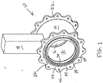
- the apparatus 10 includes one or more shrouded end fittings 22.
- An end fitting 22 may be used to connect the shrouded valve apparatus 10, for example, with a shrouded fluid-conducting apparatus as further described below.
- the shrouded valve apparatus 10 may be connected by way of the shrouded end fittings 22 to any one of a wide range of other fluid-conducting apparatus having end fittings mateable or engageable with the shrouded end fittings 22, as would be obvious to one having ordinary skill in the art after having become familiar with the teaching of the present invention.
- the shrouded end fittings 22 are used to hold or keep the inner conduit 12 substantially stationary with respect to the outer conduit 14 and/or to transfer loads from the inner and outer conduits 12 and 14 to an external component (e.g., ceiling joists, floor beams, and other load-bearing structures).
- an external component e.g., ceiling joists, floor beams, and other load-bearing structures.
- the shrouded end fitting 22 includes an inner portion 30 and an outer portion 34 that are separated by a spaced distance 38.
- the outer portion 34 includes a flange 42 that defines a plurality of holes 46 sized to receive the mechanical fasteners (not shown in Figure 1 ) therethrough.
- the shrouded end fitting 22 includes a plurality of spokes, webs, or fins 50 that are disposed between the inner and outer portions 30 and 34.
- one or more of the fins 50 of the shrouded end fitting 22 may be configured for allowing installation of at least a portion or a component of a fluid control system therein. That is, one or more of the fins 50 may be sufficiently thick to allow a passageway to be provided therethrough, which may be used for installation of a union or pipe coupling, a drain, a pressure regulator, and/or other components of a fluid control system.
- a union or pipe coupling a drain, a pressure regulator, and/or other components of a fluid control system.
- any of a wide range of materials and manufacturing processes may be used to produce the shrouded end fittings 22.
- the selection of material may depend at least in part on the materials comprising the inner and outer conduits 12 and 14 and the manner in which the inner and outer conduits 12 and 14 will be engaged with the shrouded end fittings 22.
- the selection of manufacturing process may depend at least in part on the material that is selected for the shrouded end fittings 22.
- the shrouded end fittings 22 may include aluminum (e.g., 6061-T4 aluminum) and/or stainless steel and may be formed by a machining and/or milling process.
- the apparatus 110 includes an inner conduit 112 disposed within an outer conduit 114.
- the inner conduit 112 includes a lumen 116 that allows for a fluid flow (e.g., flow of gases and/or liquids) through the inner conduit 112.
- a valve actuator 118 is operable to activate a valve member (not shown in Figure 1 ) disposed in the inner conduit 112, to regulate flow through the inner conduit 112.
- the outer conduit 114 and actuator 118 cooperate to shroud the inner conduit 112, to contain in the outer conduit 114 any fluid leaking from the inner conduit 112.
- the apparatus 110 includes two shrouded end fittings 122.
- An end fitting 122 is used to connect the shrouded valve apparatus 110 with a shrouded fluid-conducting apparatus as further described below.
- the valve apparatus 110 is fabricated by joining two parts 160 and 164 together to form a flange. The parts 160 and 164 are bolted or screwed together at holes 172.
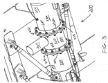
- a bottom perspective view of a shrouded valve apparatus in use is indicated generally in Figure 3 by reference number 200.
- the shrouded valve apparatus 200 is not in accordance with the present invention, but shares features in common with the figure 2 apparatus.
- a shrouded valve apparatus 210 is connected between two fluid-conducting apparatus 220 at joints 224. Accordingly, the valve apparatus 210 includes shrouded end fittings 228 disposed at its ends, which are engaged with shrouded end fittings 232 of the two fluid-conducting apparatus 220 by mechanical fasteners 240 (e.g., lugs, clevis pins, single pin joints, screws, and/or rivets).
- the shrouded fittings 228 and 232 are configured, for example, as previously described with reference to Figure 1 .
- the shrouded fittings 228 and 232 provide fluid communication between inner conduits (not shown in Figure 3 ) of the valve apparatus 210 and the fluid-conducting apparatus 220.
- the fittings 228 and 232 also provide fluid communication between outer conduits 250 and 254 of the valve apparatus 210 and the fluid-conducting apparatus 220.
- the valve apparatus 210 also includes a valve actuator 260 further described below.
- a joint 224 is a substantially fixed joint that allows for the transfer of loads from one shrouded apparatus 210 or 220 to another shrouded apparatus and/or to an external component (e.g., ceiling joist, floor beam, other load-bearing structures, etc.).
- an external component e.g., ceiling joist, floor beam, other load-bearing structures, etc.
- joints more flexible than joints 224 could be used in other configurations.
- FIG 4 is a cross-sectional side view of the shrouded valve apparatus shown in Figure 3 .
- the apparatus 210 includes an inner conduit 312 defining an inner lumen 316.
- the actuator 260 includes a motor that turns a shaft 310 extending into the inner lumen 316 and into a pivot location 320 in the inner conduit 312.
- a valve member 324 e.g., a butterfly, is fixedly mounted on the shaft 310. In the present embodiment the valve member 324 is round and flat.
- the actuator 260 is operable to rotate the shaft 310 and valve member 324 in the pivot location 320.
- the valve member 324 thus can be selectively positioned in the inner lumen 316 to regulate flow through the inner lumen.
- valve member 324 can be positioned by the actuator 260 to provide various degrees of opening and/or closing of the inner lumen 316.
- a valve member may have another shape, for example, to accommodate an inner lumen that is not round.
- Inner and outer portions 366 and 368 of a valve apparatus shrouded end fitting 228 may be provided with notches or weld sockets 370 into which may be welded (e.g., fillet weld, butt weld, etc.) the inner and outer conduits 312 and 250, respectively.
- Inner and outer portions 374 and 376 of a shrouded end fitting 232 of an apparatus 220 may also be provided with notches or weld sockets 370 into which may be welded (e.g., fillet weld, butt weld, etc.) an inner conduit 378 and outer conduit 380, respectively, of that apparatus 220.
- the inner and outer portions of the shrouded end fittings 228 and 232 may each define grooves (not shown) in which are disposed o-rings to assist with the fluidic sealing of the joints 224.
- a shrouded end fitting 228 includes an alignment tab or key 384 that is sized to fit within a notch or keyway 386 defined by the shrouded end fitting 232.
- a shrouded end fitting 228 may, additionally or alternatively, include a radial protrusion (not shown) disposed to engage a chamfered or beveled surface defined by a shrouded end fitting 232.
- a shrouded end fitting 228 may be provided with the alignment tab and/or the radial protrusion, and the shrouded end fitting 232 may be provided with the notch and/or the chamfered surface.
- a joint 284 allows for fluid communication between the inner conduits 312 and 378 and also defines a leak detection passageway 390 that allows for fluid communication between the outer conduits 250 and 380.
- a leak detection system is not necessarily needed for each of the shrouded apparatus 210 and 220. Instead, a single leak detection system may be used to detect fluid in either of the outer conduits 250 or 380.
- the actuator 260 is affixed to the inner conduit 312 of the valve apparatus 210 in a manner that prevents fluid from crossing between the inner and outer conduits 312 and 250 but does not prevent fluid communication between portions of the outer conduit 250.
- the foregoing shrouded valve apparatus is used to regulate flow of fuel in aircraft fuel systems and to isolate one portion of the system from another.
- the valve may be closed to isolate a portion and opened to allow flow from one portion of the system to another.
- varying degrees of flow also can be achieved dependent on the position of the valve member relative to a inner conduit within the valve apparatus.
Landscapes
- Engineering & Computer Science (AREA)
- General Engineering & Computer Science (AREA)
- Mechanical Engineering (AREA)
- Valve Housings (AREA)
- Lift Valve (AREA)
- Control Of Throttle Valves Provided In The Intake System Or In The Exhaust System (AREA)
- Controls For Constant Speed Travelling (AREA)
Claims (11)
- Luftfahrzeug-Kraftstoffsystem mit einer ummantelten Ventilvorrichtung (110), wobei die ummantelte Ventilvorrichtung umfasst:eine äußere Leitung (114);eine innere Leitung (112), die innerhalb der äußeren Leitung angeordnet ist, wobei die innere Leitung (112) ein inneres Lumen (116) umfasst;ein Ventilelement, das in der inneren Leitung (112) angeordnet und zum Regulieren des Flusses durch die innere Leitung (112) betätigbar ist; undeinen Aktor (118) zum Betätigen des Ventils;wobei die ummantelte Ventilvorrichtung (110) zwei ummantelte Anschlussenden (122) zum Verbinden der ummantelten Ventilvorrichtung (110) mit ummantelten Anschlussenden einer fluidführenden Vorrichtung umfasst, wobei beide ummantelten Anschlussenden (122) die innere Leitung (112) in Bezug auf die äußere Leitung (114) in etwa ortsfest halten;dadurch gekennzeichnet, dassjedes der ummantelten Anschlussenden (122) einen inneren Abschnitt und einen äußeren Abschnitt aufweist, die durch einen Zwischenraum voneinander getrennt sind, wobei der äußere Abschnitt einen Anschlussflansch mit mehreren zur Aufnahme mechanischer Befestigungsmittel ausgebildeten Löchern aufweist;jedes der ummantelten Anschlussenden (122) mehrere Speichen, Stege oder Lamellen aufweist, die zwischen dem inneren und dem äußeren Abschnitt angeordnet sind;die ummantelte Ventilvorrichtung (110) durch Verbinden von zwei Teilen (160, 164) der äußeren Leitung hergestellt ist, um einen weiteren Flansch zu bilden, der Löcher (172) aufweist, über die die Teile (160, 164) mittels Bolzen oder Schrauben aneinander befestigt sind;der Aktor (118) an der inneren Leitung (112) der ummantelten Ventilvorrichtung (110) so angebracht ist, dass ein Übertreten von Fluid zwischen innerer (122) und äußerer (114) Leitung verhindert, eine Fluidverbindung zwischen Teilen der äußeren Leitung (114) jedoch nicht verhindert wird;die äußere Leitung (114) und der Aktor (118) zusammenwirken, um die innere Leitung (112) zu ummanteln und in der äußeren Leitung jegliches aus der inneren Leitung (112) leckende Fluid aufzufangen; undder Aktor (118) einen Motor umfasst, der einen Schaft dreht, welcher sich in das innere Lumen (116) und einen Drehpunkt in der inneren Leitung (112) erstreckt, wobei das Ventilelement fest an dem Schaft angebracht ist und wobei der Aktor (118) so betätigbar ist, dass er den Schaft und das Ventilelement im Drehpunkt dreht.
- Luftfahrzeug-Kraftstoffsystem nach Anspruch 1, wobeidie innere Leitung (1 12) eine Einrichtung zur Leitung von Kraftstoff bildet;die äußere Leitung (114) eine zweite Einrichtung bildet, um ein zweites Fluid koaxial zu und getrennt von dem Kraftstoff zu leiten; unddas Ventilelement und der Aktor (118) eine Einrichtung zum Regulieren eines Kraftstoffflusses durch die innere Leitung bilden.
- Verfahren zum Leiten von Kraftstoff in dem Luftfahrzeug-Kraftstoffsystem nach Anspruch 2, welches umfasst:
Leiten des Kraftstoffs durch die innerhalb der äußeren Leitung (114) gelegene innere Leitung (112); und Einstellen einer Flussrate des Kraftstoffs durch die innere Leitung (112), wobei das Einstellen durch Betätigen des in der inneren Leitung (112) angeordneten Ventilelements erfolgt - Luftfahrzeug-Kraftstoffsystem nach Anspruch 1, wobei das Ventilelement zum Regulieren des Flusses in der inneren Leitung (112) selektiv einstellbar ist.
- Luftfahrzeug-Kraftstoffsystem nach Anspruch 2, wobei das Ventilelement betätigbar ist, um einen die ummantelte Ventilvorrichtung (110) umfassenden Teil des Kraftstoffsystems des Luftfahrzeugs von einem anderen Teil des Kraftstoffsystems des Luftfahrzeugs abzutrennen.
- Luftfahrzeug-Kraftstoffsystem nach Anspruch 1, wobei die ummantelten Anschlussenden (122) den Transfer einer Beladung zwischen der ummantelten Ventilvorrichtung (110) und der fluidführenden Vorrichtung ermöglichen.
- Luftfahrzeug-Kraftstoffsystem nach Anspruch 1, wobei sich die äußere Leitung (114) in Fluidverbindung mit den äußeren Leitungen der fluidführenden Vorrichtung befindet.
- Luftfahrzeug-Kraftstoffsystem nach Anspruch 1, wobei der Aktor (118) und das Ventilelement eine Einstelleinrichtung zum selektiven und zumindest teilweisen Schließen des inneren Lumens (116) bilden.
- Verfahren nach Anspruch 3, das ferner das Regulieren der Flussrate durch die innere Leitung (112) umfasst, wobei gleichzeitig ein Fluidfluss durch die äußere Leitung (114) möglich ist.
- Verfahren nach Anspruch 3, das ferner ein Betätigen des Ventilelements umfasst, um einen Teil des Kraftstoffsystems des Luftfahrzeugs von einem anderen Teil des Kraftstoffsystems des Luftfahrzeugs zu trennen.
- Verfahren nach Anspruch 3, das ferner ein Betätigen des Ventilelements umfasst, um einen von mehreren Öffnungsgraden der inneren Leitung (112) einzustellen.
Applications Claiming Priority (1)
| Application Number | Priority Date | Filing Date | Title |
|---|---|---|---|
| US11/150,853 US7493911B2 (en) | 2002-08-09 | 2005-06-10 | Shrouded valve apparatus and related methods |
Publications (4)
| Publication Number | Publication Date |
|---|---|
| EP1731810A2 EP1731810A2 (de) | 2006-12-13 |
| EP1731810A3 EP1731810A3 (de) | 2007-10-10 |
| EP1731810B1 EP1731810B1 (de) | 2012-04-25 |
| EP1731810B2 true EP1731810B2 (de) | 2020-10-14 |
Family
ID=36928244
Family Applications (1)
| Application Number | Title | Priority Date | Filing Date |
|---|---|---|---|
| EP06253009.2A Active EP1731810B2 (de) | 2005-06-10 | 2006-06-12 | Eingehüllte Ventilvorrichtung und zugehörige Verfahren |
Country Status (4)
| Country | Link |
|---|---|
| US (1) | US7493911B2 (de) |
| EP (1) | EP1731810B2 (de) |
| AT (1) | ATE555339T1 (de) |
| ES (1) | ES2383533T3 (de) |
Families Citing this family (15)
| Publication number | Priority date | Publication date | Assignee | Title |
|---|---|---|---|---|
| US7437952B2 (en) * | 2005-06-10 | 2008-10-21 | The Boeing Company | Shrouded body flow meter assembly |
| US20090091126A1 (en) * | 2007-10-04 | 2009-04-09 | Carns James A | Shrouded coupling assemblies for conduits |
| US9360144B2 (en) * | 2007-10-22 | 2016-06-07 | The Boeing Company | Conduit with joint covered by a boot |
| US7942452B2 (en) * | 2007-11-20 | 2011-05-17 | The Boeing Company | Flange fitting with leak sensor port |
| US9136036B2 (en) * | 2008-07-02 | 2015-09-15 | Miller Waster Mills | Injection moldable, thermoplastic composite materials |
| US8956556B2 (en) | 2008-07-02 | 2015-02-17 | Eaton Corporation | Dielectric isolators |
| US8003014B2 (en) * | 2008-07-02 | 2011-08-23 | Eaton Corporation | Dielectric isolators |
| US9046062B2 (en) * | 2009-09-25 | 2015-06-02 | Dresser-Rand Company | Greenhouse gas capture system and method |
| FR2983276B1 (fr) * | 2011-11-30 | 2014-08-22 | Airbus Operations Sas | Dispositif de fixation d'un circuit de transport de fluide a un element de la structure d'un aeronef et aeronef associe |
| US9631765B2 (en) * | 2013-08-07 | 2017-04-25 | The Boeing Company | Systems and methods for duct protection of a vehicle |
| US9789747B2 (en) | 2014-07-31 | 2017-10-17 | The Boeing Company | Systems and methods for duct protection of a vehicle |
| US10001232B2 (en) | 2015-03-13 | 2018-06-19 | The Boeing Company | Systems and methods for duct protection |
| EP3239582B1 (de) * | 2016-04-29 | 2019-02-20 | Airbus Operations GmbH | Ummantelte ventilanordnung |
| EP3239564B1 (de) * | 2016-04-29 | 2018-12-05 | Airbus Operations GmbH | Ummantelte ventilanordnung |
| US11384883B2 (en) * | 2020-01-31 | 2022-07-12 | General Electric Company | Cryogenic transfer line coupling assembly |
Citations (7)
| Publication number | Priority date | Publication date | Assignee | Title |
|---|---|---|---|---|
| US2649769A (en) † | 1951-06-30 | 1953-08-25 | Edward W Kaiser | Jacketed valve |
| GB873146A (en) † | 1957-01-14 | 1961-07-19 | Spe Company Ltd | A fluid proportioner |
| WO1996022483A1 (de) † | 1995-01-16 | 1996-07-25 | Ideal-Standard Gmbh | Griff für eine sanitärarmatur |
| US5546977A (en) † | 1994-03-08 | 1996-08-20 | Conley Corporation | Dual containment valve system |
| US6089252A (en) † | 1998-06-16 | 2000-07-18 | Robertson Aviation Llc | Manifold for auxiliary fuel tank |
| US6178989B1 (en) † | 1996-04-19 | 2001-01-30 | Hans Windschmitt | Safety element for a duct |
| US6343596B1 (en) † | 1997-10-22 | 2002-02-05 | Pc/Rc Products, Llc | Fuel delivery regulator |
Family Cites Families (43)
| Publication number | Priority date | Publication date | Assignee | Title |
|---|---|---|---|---|
| US724675A (en) * | 1902-08-29 | 1903-04-07 | William M Ferry | Fluid-conducting pipe. |
| US2475635A (en) * | 1945-01-08 | 1949-07-12 | Elmer C Parsons | Multiple conduit |
| DE833152C (de) | 1950-09-21 | 1952-03-03 | Joseph Ecken | Beheiztes Absperrorgan und Verbindungsstueck fuer doppelwandige, beheizte Rohrleitungen |
| US2668066A (en) * | 1951-02-10 | 1954-02-02 | Berkeley Pump Company | Coupling means for tubular casing |
| GB886320A (en) | 1958-07-22 | 1962-01-03 | Atomic Energy Authority Uk | Improvements in or relating to valved ducting |
| GB1105353A (en) | 1966-03-02 | 1968-03-06 | Zentrales Entwicklungs Und Kon | Valve system for double walled or concentric pipes |
| US3747618A (en) * | 1971-08-13 | 1973-07-24 | R Boes | Automatic shut-off valve system |
| US3976100A (en) * | 1974-05-13 | 1976-08-24 | The Boeing Company | Aerial refueling apparatus |
| US3928903A (en) * | 1975-01-29 | 1975-12-30 | Atlantic Richfield Co | Method of making a double-walled pipe assembly |
| US4149739A (en) * | 1977-03-18 | 1979-04-17 | Summa Corporation | Dual passage pipe for cycling water to an undersea mineral aggregate gathering apparatus |
| US4377803A (en) * | 1980-07-02 | 1983-03-22 | International Business Machines Corporation | Algorithm for the segmentation of printed fixed pitch documents |
| AT391932B (de) | 1983-10-31 | 1990-12-27 | Wolf Erich M | Rohrleitung |
| EP0166799B1 (de) * | 1984-07-04 | 1988-05-11 | von Meyerinck, Wolfgang, Dipl.-Ing. | Betankungssystem, insbesondere für die Flugzeugbetankung |
| DE3436994C1 (de) | 1984-09-11 | 1986-02-06 | Wilhelm 4150 Krefeld Schulz | Flansch |
| CH678221A5 (de) * | 1987-11-11 | 1991-08-15 | Fischer Ag Georg | |
| US4929000A (en) * | 1988-12-02 | 1990-05-29 | American Metal Products Company | Multiple walled chimney |
| US5449203A (en) * | 1991-04-04 | 1995-09-12 | Sharp; Bruce R. | Fittings for connection to double wall pipeline systems |
| US5414850A (en) * | 1991-08-23 | 1995-05-09 | Stac Electronics, Inc. | System for transparently compressing data files in a computer system |
| US5228472A (en) * | 1992-03-16 | 1993-07-20 | Nippon Snaso Corporation | Valve unit for pipeline equipped with double flow tube |
| US5449204A (en) * | 1993-10-22 | 1995-09-12 | Greene; Karen C. | Double containment fitting |
| US5737594A (en) * | 1994-07-05 | 1998-04-07 | Trustus Pty Ltd. | Method for matching elements of two groups |
| US5822746A (en) * | 1994-07-05 | 1998-10-13 | Trustus Pty Ltd | Method for mapping a file specification to a sequence of actions |
| EP0700229B1 (de) * | 1994-08-22 | 2006-06-28 | Fujitsu Limited | Verbindungsloses Kommunikationssystem, Testmethode und Intra-Station-Steuerungssystem |
| US5990810A (en) * | 1995-02-17 | 1999-11-23 | Williams; Ross Neil | Method for partitioning a block of data into subblocks and for storing and communcating such subblocks |
| US6791947B2 (en) * | 1996-12-16 | 2004-09-14 | Juniper Networks | In-line packet processing |
| NL1007899C2 (nl) * | 1997-12-24 | 1999-06-25 | Dhv Water Bv | Koppelelement voor membraanelementen. |
| US5947151A (en) * | 1998-01-13 | 1999-09-07 | Csr Polypipe, Inc. | Dual containment valve |
| US6415329B1 (en) * | 1998-03-06 | 2002-07-02 | Massachusetts Institute Of Technology | Method and apparatus for improving efficiency of TCP/IP protocol over high delay-bandwidth network |
| US6163811A (en) * | 1998-10-21 | 2000-12-19 | Wildseed, Limited | Token based source file compression/decompression and its application |
| IT244388Y1 (it) * | 1998-11-23 | 2002-03-11 | Nupi S P A | Raccordi per tubi a doppia parete |
| US6449658B1 (en) * | 1999-11-18 | 2002-09-10 | Quikcat.Com, Inc. | Method and apparatus for accelerating data through communication networks |
| US6553141B1 (en) * | 2000-01-21 | 2003-04-22 | Stentor, Inc. | Methods and apparatus for compression of transform data |
| US7047281B1 (en) * | 2000-08-08 | 2006-05-16 | Fineground Networks | Method and system for accelerating the delivery of content in a networked environment |
| DE20013627U1 (de) | 2000-08-08 | 2002-01-10 | Chemie- und Tankanlagenbau Reuther GmbH, 15517 Fürstenwalde | Vorrichtung zum Lagern von Flüssigkeiten |
| JP2004518327A (ja) * | 2001-01-11 | 2004-06-17 | コーニンクレッカ フィリップス エレクトロニクス エヌ ヴィ | 逆進的にストリングを参照する為の識別子を用いたデータ圧縮方法 |
| DE10102398A1 (de) | 2001-01-19 | 2002-07-25 | Zimmer Ag | Verschlusskörper zum Verschließen einer Rohrleitung und Verfahren hierzu |
| US7310687B2 (en) * | 2001-03-23 | 2007-12-18 | Cisco Technology, Inc. | Methods and systems for managing class-based condensation |
| US7159014B2 (en) * | 2001-06-04 | 2007-01-02 | Fineground Networks | Method and system for efficient and automated version management of embedded objects in web documents |
| TW569191B (en) * | 2002-01-15 | 2004-01-01 | Benq Corp | Apparatus for reducing running-noise in a disk drive |
| DE20209981U1 (de) | 2002-06-27 | 2002-11-21 | Daume Regelarmaturen GmbH, 30916 Isernhagen | Ventilanordnung zur Verwendung in Rohrleitungssystemen für strömungsfähige Medien |
| US6678828B1 (en) * | 2002-07-22 | 2004-01-13 | Vormetric, Inc. | Secure network file access control system |
| US6848720B2 (en) * | 2002-08-09 | 2005-02-01 | The Boeing Company | Shrouded fluid-conducting apparatus |
| US6667700B1 (en) * | 2002-10-30 | 2003-12-23 | Nbt Technology, Inc. | Content-based segmentation scheme for data compression in storage and transmission including hierarchical segment representation |
-
2005
- 2005-06-10 US US11/150,853 patent/US7493911B2/en not_active Expired - Lifetime
-
2006
- 2006-06-12 AT AT06253009T patent/ATE555339T1/de active
- 2006-06-12 ES ES06253009T patent/ES2383533T3/es active Active
- 2006-06-12 EP EP06253009.2A patent/EP1731810B2/de active Active
Patent Citations (7)
| Publication number | Priority date | Publication date | Assignee | Title |
|---|---|---|---|---|
| US2649769A (en) † | 1951-06-30 | 1953-08-25 | Edward W Kaiser | Jacketed valve |
| GB873146A (en) † | 1957-01-14 | 1961-07-19 | Spe Company Ltd | A fluid proportioner |
| US5546977A (en) † | 1994-03-08 | 1996-08-20 | Conley Corporation | Dual containment valve system |
| WO1996022483A1 (de) † | 1995-01-16 | 1996-07-25 | Ideal-Standard Gmbh | Griff für eine sanitärarmatur |
| US6178989B1 (en) † | 1996-04-19 | 2001-01-30 | Hans Windschmitt | Safety element for a duct |
| US6343596B1 (en) † | 1997-10-22 | 2002-02-05 | Pc/Rc Products, Llc | Fuel delivery regulator |
| US6089252A (en) † | 1998-06-16 | 2000-07-18 | Robertson Aviation Llc | Manifold for auxiliary fuel tank |
Non-Patent Citations (1)
| Title |
|---|
| Federal Aviation Administration, AC 25-8 Auxiliary Fuel Systems Installations 02.05.1986. Available from: http://www.faa.gov/regulations.policies/advisory_circulars/index.cfm/go/document.Information/documentID/22463. † |
Also Published As
| Publication number | Publication date |
|---|---|
| ATE555339T1 (de) | 2012-05-15 |
| EP1731810A3 (de) | 2007-10-10 |
| US7493911B2 (en) | 2009-02-24 |
| US20070051406A1 (en) | 2007-03-08 |
| ES2383533T3 (es) | 2012-06-22 |
| EP1731810B1 (de) | 2012-04-25 |
| EP1731810A2 (de) | 2006-12-13 |
Similar Documents
| Publication | Publication Date | Title |
|---|---|---|
| EP1731810B2 (de) | Eingehüllte Ventilvorrichtung und zugehörige Verfahren | |
| US6848720B2 (en) | Shrouded fluid-conducting apparatus | |
| EP0351155B1 (de) | Erweiterbarer Verteiler für ein Wasserversorgungssystem | |
| GB2410073A (en) | Pressure compensated shear seal solenoid valve | |
| EP2957798B1 (de) | Hochtemperaturventil | |
| US6240941B1 (en) | Modular, interconnectable valve | |
| US20220268381A1 (en) | Fluid conduit assembly | |
| CA2261322C (en) | Supply device for gas appliance manifold | |
| US10145478B2 (en) | Top entry soft seats floating ball valve | |
| US7152630B2 (en) | Fluid system coupling | |
| US5887619A (en) | Dry disconnect coupling assembly | |
| EP1864043B1 (de) | Verteiler | |
| CA2389836C (en) | Emergency shutdown valve actuator | |
| US7871110B2 (en) | Sealing element and a coupling device and a valve device provided with such a sealing element | |
| PL185012B1 (pl) | Zawór wzniosowy o krótkiej konstrukcji | |
| EP1395768B1 (de) | Vorrichtung zum durchführen einer leitung oder dergleichen durch ein bauelement | |
| US3599932A (en) | Between flange journaled ball valve assembly | |
| US20070039657A1 (en) | Fluid system coupling with pin lock | |
| EP4093996B1 (de) | Prozesssteuersysteme und zugehörige monoflansche | |
| EP4087783B1 (de) | Flügel-pylon-verbindung für flugzeug | |
| JP3117350B2 (ja) | 三方向切換えバタフライ弁装置 | |
| US4580599A (en) | Valve assembly for relieving pressure on a process structure | |
| EP1882097B1 (de) | Kraftstoffverteiler, montagesystem dafür und verfahren zur montage eines kraftstoffverteilers | |
| US11226049B2 (en) | Fluid supply system | |
| CA2991728C (en) | Blind flange and method of installing same for isolating hazardous energy within a facility |
Legal Events
| Date | Code | Title | Description |
|---|---|---|---|
| PUAI | Public reference made under article 153(3) epc to a published international application that has entered the european phase |
Free format text: ORIGINAL CODE: 0009012 |
|
| 17P | Request for examination filed |
Effective date: 20060619 |
|
| AK | Designated contracting states |
Kind code of ref document: A2 Designated state(s): AT BE BG CH CY CZ DE DK EE ES FI FR GB GR HU IE IS IT LI LT LU LV MC NL PL PT RO SE SI SK TR |
|
| AX | Request for extension of the european patent |
Extension state: AL BA HR MK YU |
|
| PUAL | Search report despatched |
Free format text: ORIGINAL CODE: 0009013 |
|
| AK | Designated contracting states |
Kind code of ref document: A3 Designated state(s): AT BE BG CH CY CZ DE DK EE ES FI FR GB GR HU IE IS IT LI LT LU LV MC NL PL PT RO SE SI SK TR |
|
| AX | Request for extension of the european patent |
Extension state: AL BA HR MK YU |
|
| AKX | Designation fees paid |
Designated state(s): AT BE BG CH CY CZ DE DK EE ES FI FR GB GR HU IE IS IT LI LT LU LV MC NL PL PT RO SE SI SK TR |
|
| 17Q | First examination report despatched |
Effective date: 20080526 |
|
| GRAP | Despatch of communication of intention to grant a patent |
Free format text: ORIGINAL CODE: EPIDOSNIGR1 |
|
| GRAC | Information related to communication of intention to grant a patent modified |
Free format text: ORIGINAL CODE: EPIDOSCIGR1 |
|
| RIN1 | Information on inventor provided before grant (corrected) |
Inventor name: CARNS, JAMES A. Inventor name: SHELLY, MARK A. Inventor name: VAN KAMPEN, BENJAMIN P. Inventor name: CUTLER, THERON L. |
|
| GRAS | Grant fee paid |
Free format text: ORIGINAL CODE: EPIDOSNIGR3 |
|
| GRAA | (expected) grant |
Free format text: ORIGINAL CODE: 0009210 |
|
| AK | Designated contracting states |
Kind code of ref document: B1 Designated state(s): AT BE BG CH CY CZ DE DK EE ES FI FR GB GR HU IE IS IT LI LT LU LV MC NL PL PT RO SE SI SK TR |
|
| REG | Reference to a national code |
Ref country code: GB Ref legal event code: FG4D |
|
| REG | Reference to a national code |
Ref country code: CH Ref legal event code: EP |
|
| REG | Reference to a national code |
Ref country code: AT Ref legal event code: REF Ref document number: 555339 Country of ref document: AT Kind code of ref document: T Effective date: 20120515 |
|
| REG | Reference to a national code |
Ref country code: IE Ref legal event code: FG4D |
|
| REG | Reference to a national code |
Ref country code: DE Ref legal event code: R096 Ref document number: 602006029040 Country of ref document: DE Effective date: 20120621 |
|
| REG | Reference to a national code |
Ref country code: ES Ref legal event code: FG2A Ref document number: 2383533 Country of ref document: ES Kind code of ref document: T3 Effective date: 20120622 |
|
| REG | Reference to a national code |
Ref country code: NL Ref legal event code: VDEP Effective date: 20120425 |
|
| REG | Reference to a national code |
Ref country code: AT Ref legal event code: MK05 Ref document number: 555339 Country of ref document: AT Kind code of ref document: T Effective date: 20120425 |
|
| LTIE | Lt: invalidation of european patent or patent extension |
Effective date: 20120425 |
|
| PG25 | Lapsed in a contracting state [announced via postgrant information from national office to epo] |
Ref country code: CY Free format text: LAPSE BECAUSE OF FAILURE TO SUBMIT A TRANSLATION OF THE DESCRIPTION OR TO PAY THE FEE WITHIN THE PRESCRIBED TIME-LIMIT Effective date: 20120425 Ref country code: FI Free format text: LAPSE BECAUSE OF FAILURE TO SUBMIT A TRANSLATION OF THE DESCRIPTION OR TO PAY THE FEE WITHIN THE PRESCRIBED TIME-LIMIT Effective date: 20120425 Ref country code: PL Free format text: LAPSE BECAUSE OF FAILURE TO SUBMIT A TRANSLATION OF THE DESCRIPTION OR TO PAY THE FEE WITHIN THE PRESCRIBED TIME-LIMIT Effective date: 20120425 Ref country code: SE Free format text: LAPSE BECAUSE OF FAILURE TO SUBMIT A TRANSLATION OF THE DESCRIPTION OR TO PAY THE FEE WITHIN THE PRESCRIBED TIME-LIMIT Effective date: 20120425 Ref country code: LT Free format text: LAPSE BECAUSE OF FAILURE TO SUBMIT A TRANSLATION OF THE DESCRIPTION OR TO PAY THE FEE WITHIN THE PRESCRIBED TIME-LIMIT Effective date: 20120425 Ref country code: IS Free format text: LAPSE BECAUSE OF FAILURE TO SUBMIT A TRANSLATION OF THE DESCRIPTION OR TO PAY THE FEE WITHIN THE PRESCRIBED TIME-LIMIT Effective date: 20120825 |
|
| PG25 | Lapsed in a contracting state [announced via postgrant information from national office to epo] |
Ref country code: GR Free format text: LAPSE BECAUSE OF FAILURE TO SUBMIT A TRANSLATION OF THE DESCRIPTION OR TO PAY THE FEE WITHIN THE PRESCRIBED TIME-LIMIT Effective date: 20120726 Ref country code: PT Free format text: LAPSE BECAUSE OF FAILURE TO SUBMIT A TRANSLATION OF THE DESCRIPTION OR TO PAY THE FEE WITHIN THE PRESCRIBED TIME-LIMIT Effective date: 20120827 Ref country code: LV Free format text: LAPSE BECAUSE OF FAILURE TO SUBMIT A TRANSLATION OF THE DESCRIPTION OR TO PAY THE FEE WITHIN THE PRESCRIBED TIME-LIMIT Effective date: 20120425 Ref country code: SI Free format text: LAPSE BECAUSE OF FAILURE TO SUBMIT A TRANSLATION OF THE DESCRIPTION OR TO PAY THE FEE WITHIN THE PRESCRIBED TIME-LIMIT Effective date: 20120425 |
|
| PG25 | Lapsed in a contracting state [announced via postgrant information from national office to epo] |
Ref country code: BE Free format text: LAPSE BECAUSE OF FAILURE TO SUBMIT A TRANSLATION OF THE DESCRIPTION OR TO PAY THE FEE WITHIN THE PRESCRIBED TIME-LIMIT Effective date: 20120425 |
|
| PG25 | Lapsed in a contracting state [announced via postgrant information from national office to epo] |
Ref country code: RO Free format text: LAPSE BECAUSE OF FAILURE TO SUBMIT A TRANSLATION OF THE DESCRIPTION OR TO PAY THE FEE WITHIN THE PRESCRIBED TIME-LIMIT Effective date: 20120425 Ref country code: DK Free format text: LAPSE BECAUSE OF FAILURE TO SUBMIT A TRANSLATION OF THE DESCRIPTION OR TO PAY THE FEE WITHIN THE PRESCRIBED TIME-LIMIT Effective date: 20120425 Ref country code: EE Free format text: LAPSE BECAUSE OF FAILURE TO SUBMIT A TRANSLATION OF THE DESCRIPTION OR TO PAY THE FEE WITHIN THE PRESCRIBED TIME-LIMIT Effective date: 20120425 Ref country code: NL Free format text: LAPSE BECAUSE OF FAILURE TO SUBMIT A TRANSLATION OF THE DESCRIPTION OR TO PAY THE FEE WITHIN THE PRESCRIBED TIME-LIMIT Effective date: 20120425 Ref country code: CZ Free format text: LAPSE BECAUSE OF FAILURE TO SUBMIT A TRANSLATION OF THE DESCRIPTION OR TO PAY THE FEE WITHIN THE PRESCRIBED TIME-LIMIT Effective date: 20120425 Ref country code: SK Free format text: LAPSE BECAUSE OF FAILURE TO SUBMIT A TRANSLATION OF THE DESCRIPTION OR TO PAY THE FEE WITHIN THE PRESCRIBED TIME-LIMIT Effective date: 20120425 Ref country code: AT Free format text: LAPSE BECAUSE OF FAILURE TO SUBMIT A TRANSLATION OF THE DESCRIPTION OR TO PAY THE FEE WITHIN THE PRESCRIBED TIME-LIMIT Effective date: 20120425 Ref country code: MC Free format text: LAPSE BECAUSE OF NON-PAYMENT OF DUE FEES Effective date: 20120630 |
|
| REG | Reference to a national code |
Ref country code: CH Ref legal event code: PL |
|
| PLBI | Opposition filed |
Free format text: ORIGINAL CODE: 0009260 |
|
| REG | Reference to a national code |
Ref country code: CH Ref legal event code: PL |
|
| PG25 | Lapsed in a contracting state [announced via postgrant information from national office to epo] |
Ref country code: IT Free format text: LAPSE BECAUSE OF FAILURE TO SUBMIT A TRANSLATION OF THE DESCRIPTION OR TO PAY THE FEE WITHIN THE PRESCRIBED TIME-LIMIT Effective date: 20120425 |
|
| PLAX | Notice of opposition and request to file observation + time limit sent |
Free format text: ORIGINAL CODE: EPIDOSNOBS2 |
|
| 26 | Opposition filed |
Opponent name: AIRBUS OPERATIONS LIMITED(GB)/AIRBUS SAS(FR)AIRBUS Effective date: 20130125 |
|
| REG | Reference to a national code |
Ref country code: IE Ref legal event code: MM4A |
|
| REG | Reference to a national code |
Ref country code: DE Ref legal event code: R026 Ref document number: 602006029040 Country of ref document: DE Effective date: 20130125 |
|
| PG25 | Lapsed in a contracting state [announced via postgrant information from national office to epo] |
Ref country code: LI Free format text: LAPSE BECAUSE OF NON-PAYMENT OF DUE FEES Effective date: 20120630 Ref country code: IE Free format text: LAPSE BECAUSE OF NON-PAYMENT OF DUE FEES Effective date: 20120612 Ref country code: CH Free format text: LAPSE BECAUSE OF NON-PAYMENT OF DUE FEES Effective date: 20120630 |
|
| PLAF | Information modified related to communication of a notice of opposition and request to file observations + time limit |
Free format text: ORIGINAL CODE: EPIDOSCOBS2 |
|
| PLBB | Reply of patent proprietor to notice(s) of opposition received |
Free format text: ORIGINAL CODE: EPIDOSNOBS3 |
|
| PG25 | Lapsed in a contracting state [announced via postgrant information from national office to epo] |
Ref country code: BG Free format text: LAPSE BECAUSE OF FAILURE TO SUBMIT A TRANSLATION OF THE DESCRIPTION OR TO PAY THE FEE WITHIN THE PRESCRIBED TIME-LIMIT Effective date: 20120725 |
|
| PG25 | Lapsed in a contracting state [announced via postgrant information from national office to epo] |
Ref country code: TR Free format text: LAPSE BECAUSE OF FAILURE TO SUBMIT A TRANSLATION OF THE DESCRIPTION OR TO PAY THE FEE WITHIN THE PRESCRIBED TIME-LIMIT Effective date: 20120425 |
|
| PG25 | Lapsed in a contracting state [announced via postgrant information from national office to epo] |
Ref country code: LU Free format text: LAPSE BECAUSE OF NON-PAYMENT OF DUE FEES Effective date: 20120612 |
|
| PG25 | Lapsed in a contracting state [announced via postgrant information from national office to epo] |
Ref country code: HU Free format text: LAPSE BECAUSE OF FAILURE TO SUBMIT A TRANSLATION OF THE DESCRIPTION OR TO PAY THE FEE WITHIN THE PRESCRIBED TIME-LIMIT Effective date: 20060612 |
|
| APBM | Appeal reference recorded |
Free format text: ORIGINAL CODE: EPIDOSNREFNO |
|
| APBP | Date of receipt of notice of appeal recorded |
Free format text: ORIGINAL CODE: EPIDOSNNOA2O |
|
| APAH | Appeal reference modified |
Free format text: ORIGINAL CODE: EPIDOSCREFNO |
|
| PLAB | Opposition data, opponent's data or that of the opponent's representative modified |
Free format text: ORIGINAL CODE: 0009299OPPO |
|
| R26 | Opposition filed (corrected) |
Opponent name: AIRBUS OPERATIONS LIMITED(GB)/AIRBUS SAS(FR)AIRBUS Effective date: 20130125 |
|
| APBQ | Date of receipt of statement of grounds of appeal recorded |
Free format text: ORIGINAL CODE: EPIDOSNNOA3O |
|
| REG | Reference to a national code |
Ref country code: FR Ref legal event code: PLFP Year of fee payment: 11 |
|
| REG | Reference to a national code |
Ref country code: FR Ref legal event code: PLFP Year of fee payment: 12 |
|
| REG | Reference to a national code |
Ref country code: FR Ref legal event code: PLFP Year of fee payment: 13 |
|
| APBU | Appeal procedure closed |
Free format text: ORIGINAL CODE: EPIDOSNNOA9O |
|
| PUAH | Patent maintained in amended form |
Free format text: ORIGINAL CODE: 0009272 |
|
| STAA | Information on the status of an ep patent application or granted ep patent |
Free format text: STATUS: PATENT MAINTAINED AS AMENDED |
|
| 27A | Patent maintained in amended form |
Effective date: 20201014 |
|
| AK | Designated contracting states |
Kind code of ref document: B2 Designated state(s): AT BE BG CH CY CZ DE DK EE ES FI FR GB GR HU IE IS IT LI LT LU LV MC NL PL PT RO SE SI SK TR |
|
| REG | Reference to a national code |
Ref country code: DE Ref legal event code: R102 Ref document number: 602006029040 Country of ref document: DE |
|
| PGFP | Annual fee paid to national office [announced via postgrant information from national office to epo] |
Ref country code: ES Payment date: 20200701 Year of fee payment: 15 |
|
| PG25 | Lapsed in a contracting state [announced via postgrant information from national office to epo] |
Ref country code: ES Free format text: LAPSE BECAUSE OF FAILURE TO SUBMIT A TRANSLATION OF THE DESCRIPTION OR TO PAY THE FEE WITHIN THE PRESCRIBED TIME-LIMIT Effective date: 20201014 |
|
| P01 | Opt-out of the competence of the unified patent court (upc) registered |
Effective date: 20230503 |
|
| PGFP | Annual fee paid to national office [announced via postgrant information from national office to epo] |
Ref country code: DE Payment date: 20250627 Year of fee payment: 20 |
|
| PGFP | Annual fee paid to national office [announced via postgrant information from national office to epo] |
Ref country code: GB Payment date: 20250627 Year of fee payment: 20 |
|
| PGFP | Annual fee paid to national office [announced via postgrant information from national office to epo] |
Ref country code: FR Payment date: 20250625 Year of fee payment: 20 |