EP1731809B1 - Switching mechanism for multiple treatment devices - Google Patents
Switching mechanism for multiple treatment devices Download PDFInfo
- Publication number
- EP1731809B1 EP1731809B1 EP06011192A EP06011192A EP1731809B1 EP 1731809 B1 EP1731809 B1 EP 1731809B1 EP 06011192 A EP06011192 A EP 06011192A EP 06011192 A EP06011192 A EP 06011192A EP 1731809 B1 EP1731809 B1 EP 1731809B1
- Authority
- EP
- European Patent Office
- Prior art keywords
- valve
- switching
- sealing
- switching apparatus
- seal
- Prior art date
- Legal status (The legal status is an assumption and is not a legal conclusion. Google has not performed a legal analysis and makes no representation as to the accuracy of the status listed.)
- Active
Links
- 238000007789 sealing Methods 0.000 claims description 99
- 239000012530 fluid Substances 0.000 claims description 27
- 238000001914 filtration Methods 0.000 claims description 6
- 230000005484 gravity Effects 0.000 claims description 4
- 238000004065 wastewater treatment Methods 0.000 abstract description 2
- 238000013022 venting Methods 0.000 description 22
- 239000007789 gas Substances 0.000 description 7
- 238000012423 maintenance Methods 0.000 description 5
- 230000000903 blocking effect Effects 0.000 description 4
- 239000004696 Poly ether ether ketone Substances 0.000 description 3
- 238000000034 method Methods 0.000 description 3
- 229920002530 polyetherether ketone Polymers 0.000 description 3
- 229920001343 polytetrafluoroethylene Polymers 0.000 description 3
- 239000004810 polytetrafluoroethylene Substances 0.000 description 3
- 238000009423 ventilation Methods 0.000 description 3
- 238000011109 contamination Methods 0.000 description 2
- 238000012986 modification Methods 0.000 description 2
- 230000004048 modification Effects 0.000 description 2
- 238000000926 separation method Methods 0.000 description 2
- 230000000712 assembly Effects 0.000 description 1
- 238000000429 assembly Methods 0.000 description 1
- 230000000740 bleeding effect Effects 0.000 description 1
- 238000010276 construction Methods 0.000 description 1
- 230000008878 coupling Effects 0.000 description 1
- 238000010168 coupling process Methods 0.000 description 1
- 238000005859 coupling reaction Methods 0.000 description 1
- 230000000694 effects Effects 0.000 description 1
- 239000000314 lubricant Substances 0.000 description 1
- 238000004519 manufacturing process Methods 0.000 description 1
- 239000003921 oil Substances 0.000 description 1
- 230000002093 peripheral effect Effects 0.000 description 1
- -1 polytetrafluoroethylene Polymers 0.000 description 1
- 230000036316 preload Effects 0.000 description 1
- 230000000284 resting effect Effects 0.000 description 1
- 230000000717 retained effect Effects 0.000 description 1
- 238000007493 shaping process Methods 0.000 description 1
- 231100000331 toxic Toxicity 0.000 description 1
- 230000002588 toxic effect Effects 0.000 description 1
Images

Classifications
-
- F—MECHANICAL ENGINEERING; LIGHTING; HEATING; WEAPONS; BLASTING
- F16—ENGINEERING ELEMENTS AND UNITS; GENERAL MEASURES FOR PRODUCING AND MAINTAINING EFFECTIVE FUNCTIONING OF MACHINES OR INSTALLATIONS; THERMAL INSULATION IN GENERAL
- F16K—VALVES; TAPS; COCKS; ACTUATING-FLOATS; DEVICES FOR VENTING OR AERATING
- F16K5/00—Plug valves; Taps or cocks comprising only cut-off apparatus having at least one of the sealing faces shaped as a more or less complete surface of a solid of revolution, the opening and closing movement being predominantly rotary
- F16K5/06—Plug valves; Taps or cocks comprising only cut-off apparatus having at least one of the sealing faces shaped as a more or less complete surface of a solid of revolution, the opening and closing movement being predominantly rotary with plugs having spherical surfaces; Packings therefor
- F16K5/0663—Packings
- F16K5/0673—Composite packings
-
- B—PERFORMING OPERATIONS; TRANSPORTING
- B01—PHYSICAL OR CHEMICAL PROCESSES OR APPARATUS IN GENERAL
- B01D—SEPARATION
- B01D35/00—Filtering devices having features not specifically covered by groups B01D24/00 - B01D33/00, or for applications not specifically covered by groups B01D24/00 - B01D33/00; Auxiliary devices for filtration; Filter housing constructions
- B01D35/12—Devices for taking out of action one or more units of multi- unit filters, e.g. for regeneration
-
- F—MECHANICAL ENGINEERING; LIGHTING; HEATING; WEAPONS; BLASTING
- F16—ENGINEERING ELEMENTS AND UNITS; GENERAL MEASURES FOR PRODUCING AND MAINTAINING EFFECTIVE FUNCTIONING OF MACHINES OR INSTALLATIONS; THERMAL INSULATION IN GENERAL
- F16K—VALVES; TAPS; COCKS; ACTUATING-FLOATS; DEVICES FOR VENTING OR AERATING
- F16K11/00—Multiple-way valves, e.g. mixing valves; Pipe fittings incorporating such valves
- F16K11/10—Multiple-way valves, e.g. mixing valves; Pipe fittings incorporating such valves with two or more closure members not moving as a unit
- F16K11/14—Multiple-way valves, e.g. mixing valves; Pipe fittings incorporating such valves with two or more closure members not moving as a unit operated by one actuating member, e.g. a handle
- F16K11/16—Multiple-way valves, e.g. mixing valves; Pipe fittings incorporating such valves with two or more closure members not moving as a unit operated by one actuating member, e.g. a handle which only slides, or only turns, or only swings in one plane
- F16K11/163—Multiple-way valves, e.g. mixing valves; Pipe fittings incorporating such valves with two or more closure members not moving as a unit operated by one actuating member, e.g. a handle which only slides, or only turns, or only swings in one plane only turns
-
- F—MECHANICAL ENGINEERING; LIGHTING; HEATING; WEAPONS; BLASTING
- F16—ENGINEERING ELEMENTS AND UNITS; GENERAL MEASURES FOR PRODUCING AND MAINTAINING EFFECTIVE FUNCTIONING OF MACHINES OR INSTALLATIONS; THERMAL INSULATION IN GENERAL
- F16K—VALVES; TAPS; COCKS; ACTUATING-FLOATS; DEVICES FOR VENTING OR AERATING
- F16K35/00—Means to prevent accidental or unauthorised actuation
- F16K35/14—Means to prevent accidental or unauthorised actuation interlocking two or more valves
-
- B—PERFORMING OPERATIONS; TRANSPORTING
- B01—PHYSICAL OR CHEMICAL PROCESSES OR APPARATUS IN GENERAL
- B01D—SEPARATION
- B01D2201/00—Details relating to filtering apparatus
- B01D2201/16—Valves
- B01D2201/165—Multi-way valves
Landscapes
- Engineering & Computer Science (AREA)
- General Engineering & Computer Science (AREA)
- Mechanical Engineering (AREA)
- Chemical & Material Sciences (AREA)
- Chemical Kinetics & Catalysis (AREA)
- Multiple-Way Valves (AREA)
- Taps Or Cocks (AREA)
- Use Of Switch Circuits For Exchanges And Methods Of Control Of Multiplex Exchanges (AREA)
- Electrotherapy Devices (AREA)
- Farming Of Fish And Shellfish (AREA)
- Biological Treatment Of Waste Water (AREA)
Abstract
Description
Die Erfindung betrifft eine Schaltvorrichtung für Mehrfachbehandlungsvorrichtungen für einen Fluidstrom, insbesondere für Doppelfilter zum Filtern eines Fluidstroms, mit einem einlaßseitigen Verteilventil, mit einem auslaßseitigen Verteilventil, mit jeweils einer Einlaßverbindungsleitung sowie einer Auslaßverbindungsleitung für jede Behandlungsvorrichtung, die mit Ventilanschlüssen der Verteilventile verbunden sind, mit einem im Ventilgehäuse jedes Verteilventils angeordneten kugelförmigen Ventilkörper, der zwischen zwei Schaltstellungen hin- und herbewegbar ist, wobei in den Schaltstellungen jeweils eine der Behandlungsvorrichtungen mit dem Fluidstrom beaufschlagt ist und die anderen Behandlungsvorrichtungen vom Fluidstrom abgesperrt sind, mit einer Schaltwelle, die die Ventilkörper des einlaßseitigen und des auslaßseitigen Verteilventils für deren simultane Betätigung drehfest miteinander verbindet; und mit an der Oberfläche des Ventilkörpers anliegenden Dichtungselementen für einen Dichtsitz an jedem Ventilanschluß.The invention relates to a switching device for multi-treatment devices for a fluid flow, in particular for double filter for filtering a fluid flow, with an inlet-side distribution valve, with an outlet-side distribution valve, each with an inlet connection line and an outlet connection line for each treatment device, which are connected to valve terminals of the distribution valves, with a in the valve housing of each distribution valve arranged spherical valve body which is reciprocable between two switching positions, wherein in the switching positions in each case one of the treatment devices is acted upon by the fluid flow and the other treatment devices are shut off from fluid flow, with a switching shaft, the valve body of the inlet side and the outlet-side distribution valve for the simultaneous actuation rotatably connected to each other; and with sealing elements for a sealing seat on each valve connection resting on the surface of the valve body.
Das bevorzugte Anwendungsgebiet der Erfindung betrifft Doppel- oder Mehrkammerfilter, die bei der Brauch- und Abwasserreinigung, der Schmierstoffilterung sowie der Filterung von Gasen eingesetzt werden und derart konzipiert sind, daß eine permanente und kontinuierliche Filterung des Fluids bzw. Fluidstroms gewährleistet ist. Hierzu weisen die Doppelfilter einlaßseitige und auslaßseitige Verteilventile auf, welche über eine gemeinsame Schaltwelle miteinander verbunden sind und durch Betätigen eines einzigen Schalthebels simultan betätig werden.The preferred field of application of the invention relates to double or multi-chamber filters which are used in service and wastewater treatment, the Schmierstoffilterung and the filtering of gases and are designed so that a permanent and continuous filtration of the fluid or fluid flow is ensured. For this purpose, the double filter on the inlet side and outlet side distribution valves, which are connected to each other via a common switching shaft and are actuated simultaneously by operating a single lever.
Bei der Filterung insbesondere von giftigen oder umweltschädlichen Gasen wird seit wenigstens 1998 von zahlreichen Firmen wie z.B. der Firma Shell bei den Schaltarmaturen gefordert, daß jede Verbindungsleitung zu den Behandlungsvorrichtungen doppelt abzusichern ist, um selbst bei Undichtigkeiten an dem Ventilsitz bzw. Dichtsitz des Verteilventils mit dem Dichtungselement einen Gasaustritt zu verhindern. Schaltarmaturen, die eine doppelte Absicherung ermöglichen, werden im Stand der Technik häufig als "Double Block and Bleed"-Schaltarmaturen bezeichnet. Um selbst bei Versagen einer oder beider Dichtstellen kein Gas in die abgesperrte Kammer zu bekommen, befindet sich zwischen den Dichtstellen ein sogenannter Bleed-Anschluß mit Entlüftungs- oder Zwischenabsaugungseinrichtungen für die "bleed"-Funktion.In the filtering of, in particular, toxic or polluting gases, since at least 1998 many companies, such as e.g. Shell requires the switchgear assemblies to double-secure each connection line to the treatment devices in order to prevent gas leakage even in the event of leaks at the valve seat or sealing seat of the distribution valve with the sealing element. Switching fittings that allow double protection are often referred to in the art as "double block and bleed" valves. In order to get even in case of failure of one or both sealing points no gas in the shut-off chamber, located between the sealing points is a so-called bleed connection with bleeding or Zwischenabsaugungseinrichtungen for the "bleed" function.
In der
Aufgabe der Erfindung ist es, eine Schaltvorrichtung für Mehrfachbehandlungsvorrichtungen, insbesondere für Doppelfilter, zu schaffen, die weiterhin eine Doppelabdichtung (double block) und eine Zwischenabsaugung bzw. Entlüftung (Bleed) und einen Druckausgleich ermöglicht, jedoch wesentlich einfacher zu schalten ist und mit einer geringeren Anzahl an Abdichtstellen zwischen den Gehäuseteilen auskommt.The object of the invention is to provide a switching device for multiple treatment devices, in particular for double filters, which further allows a double seal (double block) and an intermediate suction or vent (bleed) and pressure equalization, however, is much easier to switch and with a lower Number of sealing points between the housing parts manages.
Diese Aufgabe wird erfindungsgemäß dadurch gelöst, daß für die Abdichtung gegenüber jedem Ventilanschluß jeweils ein erstes Dichtungselement und ein separates zweites Dichtungselement an der Oberfläche des Ventilkörpers anliegen, zwischen denen ein an eine Einrichtung zur Entlüftung, Zwischenabsaugung und/oder Druckausgleich angeschlossener Entlüftungskanal ausgebildet ist. Bei der erfindungsgemäßen Lösung kann auf zusätzliche Sicherheitsventile verzichtet werden, da die doppelte Abdichtung mittels zweier Dichtungselemente je Ventilanschluß erreicht wird. Damit können Dichtstellen an Verbindungsstellen mit Gehäusen von zusätzlichen Absperrorganen, wie z.B. Sicherheitsventilen, entfallen. Gleichzeitig wird die Anzahl der notwendigen Entlüftungseinrichtungen erheblich minimiert. Außerdem braucht, obwohl eine Doppelabdichtung erhalten bleibt, nur ein einziger Schalthebel betätigt zu werden.This object is achieved in that abut for sealing against each valve connection in each case a first sealing element and a separate second sealing element on the surface of the valve body, between which a device connected to a device for venting, Zwischenabsaugung and / or pressure equalization vent channel is formed. In the solution according to the invention can be dispensed with additional safety valves, since the double seal is achieved by means of two sealing elements per valve port. This allows sealing points at joints with housings of additional shut-off devices, e.g. Safety valves, omitted. At the same time, the number of necessary ventilation devices is considerably minimized. In addition, although a double seal is maintained, only a single shift lever needs to be operated.
Um an der Kugeloberfläche ausreichend Fläche für die Anbringung von zwei abdichtend anliegenden Dichtungselementen zu erreichen, kann es erforderlich sein, Ventilkörper einzusetzen, deren Durchmesser bei gleichen Drücken bzw. Rohrleitungsanschlußdurchmessern entsprechend größer gewählt sind. Hierdurch kann sich die notwendige Größe der Gehäuse der Verteilventile ebenfalls geringfügig relativ zu den bekannten Konstruktionen erhöhen.In order to achieve sufficient surface for the attachment of two sealingly abutting sealing elements on the spherical surface, it may be necessary to use valve bodies whose diameters are selected to be correspondingly larger at equal pressures or pipe connection diameters. As a result, the necessary size of the housing of the distribution valves can also increase slightly relative to the known constructions.
Gemäß einem Ausführungsbeispiel kann der Entlüftungskanal von einer zwischen den beiden Dichtungen eines Dichtungspaares ausgebildeten Vertiefung oder Stufe im Gehäuse gebildet sein. Das zweite Dichtungselement kann wenigstens an einem Ventilanschluß in einem Endstück eines Gehäuseteils aufgenommen sein, der lösbar mit einem eine Kugelaufnahme für den Ventilkörper aufweisenden Gehäuseteil verbunden ist, wobei vorzugsweise der Entlüftungs- bzw. Zwischenabsaugkanal mittels Bohrungen oder Durchbrüchen in dem Endstück ausgebildet ist. Diese Ausgestaltung ist insbesondere an einem Ventilanschluß vorteilhaft, an dem ohnehin zwei Gehäuseteile lösbar miteinander verbunden sind, um den Ventilkörper montieren zu können. Alternativ oder zusätzlich kann die Oberfläche des Ventilkörpers an der einem Durchlaß im Ventilkörper abgewandten Rückseite mit wenigstens einer umlaufenden Nut versehen sein. Die Nut bewirkt eine zusätzliche Trennung der Dichtungselemente auf der Kugeloberfläche und verbessert die Absaugung und Zwischensammlung von Fremdkörpern, die eine der Dichtungen passiert haben. Durch die Nut entstehen auch an der Kugeloberfläche voneinander getrennte Dichtflächen. Die Vertiefung im Gehäuse und die Nut in der Oberfläche des Ventilkörpers können auch gleichzeitig vorgesehen sein, so daß Vertiefung und Nut gemeinsam einen Entlüftungskanal mit relativ großem Querschnitt bilden. Besonders vorteilhaft ist, wenn der Ventilkörper für jedes Dichtungspaar eine Nut aufweist, die in der Schaltstellung des Verteilventils, in der eine der beiden Behandlungsvorrichtungen vom Fluidstrom abgekoppelt ist, zwischen den beiden Dichtungen des zugehörigen Dichtungspaares angeordnet ist. Die andere Nut kommt dann nur in Funktion, wenn die Schaltstellung entsprechend geändert und die andere Behandlungsvorrichtung abgesperrt ist.According to one embodiment, the venting channel may be formed by a recess or step formed between the two seals of a pair of seals in the housing. The second sealing element may be accommodated at least on a valve connection in an end piece of a housing part which is detachably connected to a housing part having a ball seat for the valve body, wherein preferably the venting or Zwischenabsaugkanal is formed by means of bores or openings in the end piece. This embodiment is particularly advantageous in a valve connection, are already connected to the two housing parts releasably connected to each other to mount the valve body can. Alternatively or additionally, the surface of the valve body may be provided at the rear side facing away from a passage in the valve body with at least one circumferential groove. The groove causes an additional Separation of the sealing elements on the ball surface and improves the suction and intermediate collection of foreign bodies that have passed one of the seals. Through the groove formed on the spherical surface separate sealing surfaces. The recess in the housing and the groove in the surface of the valve body may also be provided simultaneously, so that depression and groove together form a venting channel with a relatively large cross-section. It is particularly advantageous if the valve body for each pair of seals has a groove which is arranged in the switching position of the distribution valve in which one of the two treatment devices is disconnected from the fluid flow, between the two seals of the associated seal pair. The other groove is then only in function when the switching position changed accordingly and the other treatment device is shut off.
Weiter vorzugsweise sind im Ventilgehäuse zwei Stichleitungen ausgebildet, wobei die erste Stichleitung in den Entlüftungskanal zwischen dem ersten Dichtungspaar und die zweite Stichleitung in den Entlüftungskanal für das zweite Dichtungspaar mündet. Die beiden Stichleitungen verlaufen vorzugsweise in einer Ebene, die senkrecht zur Schaltwelle steht. Die Entlüftungseinrichtung kann dann an der dem Einlaßanschluß oder Auslaßanschluß der Verteilventile gegenüberliegenden Seite des Verteilventilgehäuses angeschlossen sein. Über eine ggf. absperrbare Verbindungsleitung zwischen beiden Stichleitungen kann ein Druckausgleich stattfinden.Further preferably, two spur lines are formed in the valve housing, wherein the first spur line opens into the vent channel between the first seal pair and the second spur line in the vent channel for the second seal pair. The two stubs preferably extend in a plane which is perpendicular to the switching shaft. The venting device may then be connected to the opposite side of the distributor valve housing to the inlet connection or outlet connection of the distribution valves. An optionally closable connecting line between the two stub lines can be used to equalize the pressure.
Um eine statisch unbestimmte Anpreßsituation zwischen den beiden Dichtungselementen eines Dichtungspaares und der Kugeloberfläche zu vermeiden, ist besonders vorteilhaft, wenn eine der Dichtungen, vorzugsweise die erste, näher am Ventilanschluß angeordnete Dichtung, mit einem federnden Element, vorzugsweise einem O-Ring, auf die Oberfläche des Ventilkörpers zu vorgespannt ist und/oder die zweite Dichtung formbedingt auf die Oberfläche des Ventilkörpers zu vorgespannt ist. Die zweite Dichtung kann hierbei z.B. in PTFE (Polytetrafluorethylen) und die erste Dichtung in PEEK (Polyetheretherketon) ausgeführt sein. Besonders vorteilhaft ist, wenn beide Dichtungen als Dichtungspaare in zueinander parallelen Ebenen liegen und konzentrisch zu den zugehörigen Ventilanschlüssen und Leitungsquerschnitten ausgerichtet sind, so daß die Dichtungselemente eine Abdichtung konzentrisch zu den abzudichtenden Anschlüssen bewirken. Durch die vorgenannten Maßnahmen nehmen die von den einzelnen Dichtungselementen aufzunehmenden Flächenpressungen erheblich ab, wodurch sich die Lebensdauer der Dichtungselemente zusätzlich erhöht.In order to avoid a statically indeterminate contact pressure situation between the two sealing elements of a pair of seals and the spherical surface, it is particularly advantageous if one of the seals, preferably the first, closer to the valve port arranged seal, with a resilient element, preferably an O-ring on the surface the valve body is biased to and / or the second seal is due to the shape biased to the surface of the valve body. The second seal can in this case be made, for example, in PTFE (polytetrafluoroethylene) and the first seal in PEEK (polyetheretherketone). It is particularly advantageous if both seals are arranged as pairs of seals in mutually parallel planes and concentric are aligned with the associated valve ports and cable cross-sections, so that the sealing elements cause a seal concentric with the terminals to be sealed. As a result of the abovementioned measures, the surface pressures to be absorbed by the individual sealing elements decrease considerably, as a result of which the service life of the sealing elements is additionally increased.
Die erfindungsgemäße Ausgestaltung ermöglicht es in besonders vorteilhafter Weise, daß in den Zwischenraum zwischen den beiden Dichtungspaaren eine Anschlußbohrung für eine Differenzdruckmeßeinrichtung mündet. Mit einer Differenzdruckmeßeinrichtung kann der Verschmutzungsgrad der Filtervorrichtungen überwacht werden.The embodiment of the invention makes it possible in a particularly advantageous manner that opens into the intermediate space between the two pairs of seals a connection bore for a differential pressure measuring device. With a differential pressure measuring device, the degree of contamination of the filter devices can be monitored.
Gemäß einem weiteren Ausführungsbeispiel können beide Dichtungselemente auch unmittelbar an einem Dichtungskörper ausgebildet sein und vorzugsweise aus separaten Dichtflächen an dem Dichtkörper bestehen, zwischen denen der Entlüftungskanal ausgebildet ist. Die funktionelle Separierung der beiden Dichtelemente sowie die Doppelabdichtung an jedem Anschluß bleiben auch dann erhalten, wenn beide Dichtelemente z.B. als Dichtflächen an einem einzigen Dichtungskörper ausgebildet sind. Der Dichtungskörper kann dann insbesondere als Ring ausgebildet sein, der zwischen den durch eine Basis verbundenen Dichtflächen eine den Entlüftungskanal bildende Nuteinziehung aufweist, in die vorzugsweise mehrere Radialbohrungen münden. Die Verwendung nur eines Dichtungsringes erleichtert das Auswechseln der die Doppeldichtung gewährleistenden Dichtungselemente.According to a further embodiment, both sealing elements may also be formed directly on a sealing body and preferably consist of separate sealing surfaces on the sealing body, between which the venting channel is formed. The functional separation of the two sealing elements as well as the double seal at each connection are retained even if both sealing elements, e.g. are designed as sealing surfaces on a single seal body. The sealing body can then be designed in particular as a ring, which has, between the sealing surfaces connected by a base, a groove inlet forming the ventilation channel, into which preferably a plurality of radial bores open. The use of only one sealing ring facilitates the replacement of the double seal ensuring sealing elements.
Die Durchlaßöffnung im Ventilkörper besteht vorzugsweise aus einem sich annähernd über eine Kugelhälfte erstreckenden Schlitz, der senkrecht zur Drehachse der Schaltwelle verläuft. Mit einem Schlitz, der beispielsweise von einer geraden Einfräsung gebildet werden kann, kann gewährleistet werden, daß beim Schließen des Zuflusses zu bzw. Abfluß von einer der beiden Behandlungsvorrichtungen gleichzeitig der Zufluß/Abfluß zu bzw. von der anderen Behandlungsvorrichtung geöffnet bzw. abgesperrt wird. Besonders vorteilhaft ist, wenn der Schlitz einen ebenen Boden aufweist, bis an die Kugeloberfläche heranreicht und die Schlitzbreite dem lichten Durchmesser der verbindungsleitungen entspricht.The passage opening in the valve body preferably consists of a slot extending approximately over a half of a sphere which runs perpendicular to the axis of rotation of the control shaft. With a slot, which can be formed for example by a straight milled recess, it can be ensured that when closing the inflow to or outflow from one of the two treatment devices at the same time the inflow / outflow to or from the other treatment device is opened or shut off. It is particularly advantageous if the slot has a flat bottom, reaching up to the spherical surface and the slot width corresponds to the clear diameter of the connecting lines.
Die kugelförmigen Ventilkörper können jedoch auch eine winkelförmige, insbesondere L-förmige Durchlaßöffnung aufweisen, deren Mündungsöffnung an der Kugeloberfläche einen größeren Querschnitt als die Durchlaßöffnung aufweist, wobei vorzugsweise die Erweiterung mittels einer schlitzartigen Auffräsung gebildet ist. Mit den Erweiterungen der Mündungsöffnungen wird eine ausreichende Überdeckung gewährleistet.However, the spherical valve body may also have an angular, in particular L-shaped passage opening, the mouth opening on the ball surface has a larger cross-section than the passage opening, wherein preferably the extension is formed by a slot-like Auffräsung. With the extensions of the orifices sufficient coverage is guaranteed.
Die erfindungsgemäße Schaltvorrichtung ist grundsätzlich geeignet, automatisch, z.B. durch einen mit der Schaltwelle zusammenwirkenden motorischen Antrieb, geschaltet zu werden. In den meisten Anwendungsfällen wird jedoch an der Schaltwelle ein manuell betätigbarer Schalthebel angeschlossen sein. Insbesondere bei der Ausgestaltung mit manuell betätigbarem Schalthebel ist besonders vorteilhaft, wenn die Schaltvorrichtung eine mechanische Schaltsicherung aufweist, die ein unbeabsichtigtes Betätigen der Schaltwelle oder des Schalthebels verhindert. Die Schaltsicherung kann insbesondere einen mit dem Schalthebel zusammenwirkenden und zwischen einer Sperrstellung und einer Freigabestellung verschwenkbaren Riegel oder Bügel aufweisen. Besonders vorteilhaft ist, wenn der Riegel schwerkraftbedingt, durch Federkraft oder auf andere Weise in die Sperrstellung vorgespannt bzw. vorbelastet ist. Wenn dann der Riegel in einer der beiden Schaltstellungen, in der eine Behandlungsvorrichtung abgesperrt und die andere mit dem Fluidstrom beaufschlagt ist, unmittelbar in Schaltrichtung am Schalthebel anliegt, kann dieser Schalthebel nicht betätigt werden, solange der Riegel nicht entgegen seiner Vorbelastung angehoben, mithin weggeschwenkt, wird. Bei der Ausgestaltung mit Riegel kann dieser insbesondere an den Behandlungsvorrichtungen schwenkbar gelagert sein. Als Schaltsicherung können jedoch auch andere Vorrichtungen und Einrichtungen Verwendung finden. Bei der erfindungsgemäßen Schaltvorrichtung ist besonders vorteilhaft, wenn für jedes Verteilventil (nur) ein oder zwei Entlüftungsventile und ggf. ein Bleedventil vorgesehen ist/sind. Je nach Ventilstellung der Entlüftungs- und Bleedventile kann über die Entlüftungskanäle eine Zwischenabsaugung oder ein Druckausgleich stattfinden.The switching device according to the invention is basically suitable to be switched automatically, for example by a motor drive cooperating with the switching shaft. In most applications, however, a manually operable lever will be connected to the stem. In particular, in the embodiment with a manually operable shift lever is particularly advantageous if the switching device has a mechanical switching fuse that prevents unintentional actuation of the shift shaft or the shift lever. The switch fuse may in particular have a cooperating with the shift lever and pivotable between a blocking position and a release position bolt or strap. It is particularly advantageous if the bolt is biased by gravity or otherwise biased or biased in the blocking position by gravity. If then the bolt in one of the two switching positions, in which a treatment device shut off and the other is acted upon by the fluid flow, is applied directly in the switching direction on the shift lever, this lever can not be operated, as long as the bolt is not raised against its preload, thus pivoted away, becomes. In the embodiment with latch this can be pivotally mounted in particular on the treatment devices. As a circuit breaker, however, other devices and devices can be used. In the case of the switching device according to the invention, it is particularly advantageous if one or two bleed valves and possibly a bleed valve are / are provided for each distributor valve (only). Depending on the valve position of Venting and bleed valves can take place via the ventilation channels an intermediate suction or a pressure equalization.
Das Konzept mit einer doppelten Abdichtung an der Schaltkugel eines Verteilventils kann auch von eigenständiger erfinderischer Bedeutung sein und auch bei Schaltvorrichtungen für Doppelfilter oder bei anderen Schaltarmaturen zum Einsatz kommen. Die Erfindung kann daher auch Schaltvorrichtungen mit einem Verteilventil, mit Verbindungsleitungen z.B. für Behandlungsvorrichtungen, die an Ventilanschlüsse des Verteilventils angeschlossen sind, mit einem im Ventilgehäuse des Verteilventils angeordneten kugelförmigen Ventilkörper und mit an der Oberfläche des Ventilkörpers anliegenden Dichtungselementen für einen Dichtsitz an jedem Ventilanschluß betreffen, die dadurch gekennzeichnet sind, daß für die Abdichtung gegenüber jedem Ventilanschluß jeweils ein erstes Dichtungselement und ein separates zweites Dichtungselement an der Oberfläche des Ventilkörpers anliegen, zwischen denen ein an eine Entlüftungseinrichtung angeschlossener Entlüftungskanal ausgebildet ist.The concept with a double seal on the switching ball of a distribution valve may also be of independent inventive importance and also be used in switching devices for double filters or other switching fittings. The invention can therefore also include switching devices with a distribution valve, with connecting lines e.g. for treatment devices connected to valve ports of the distribution valve, with a spherical valve body disposed in the valve housing of the distribution valve and with sealing elements on the surface of the valve body for a sealing seat at each valve port, characterized in that for sealing against each valve port respectively a first sealing element and a separate second sealing element bear against the surface of the valve body, between which a venting device connected to a venting channel is formed.
Weitere Vorteile und Ausgestaltungen der Erfindung ergeben sich aus der nachfolgenden Beschreibung von in der Zeichnung dargestellten bevorzugten Ausführungsbeispielen. In der Zeichnung zeigen:
- Fig. 1
- in einem Vertikalschnitt einen Doppelfilter mit erfindungsgemäßer Schaltvorrichtung;
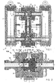
- Fig. 2
- in einem Vertikalschnitt durch eines der beiden Verteilventile die beidseitige Doppelabdichtung an der Verteilventilkugel gemäß einem ersten Ausführungsbeispiel;
- Fig. 3
- eine Detailansicht von III in
Fig. 2 ; - Fig. 4
- einen Horizontalschnitt durch das Verteilventil aus
Fig. 3 ; - Fig. 5
- perspektivisch ein Ausführungsbeispiel für eine Schaltsicherung;
- Fig. 6
- perspektivisch eine Schaltkugel für die erfindungsgemäße Schaltvorrichtung gemäß einem zweiten Ausführungsbeispiel;
- Fig. 7A,7B
- anhand von Horizontalschnitten durch die Schaltvorrichtung den Umschaltvorgang mit der Schaltkugel gemäß dem zweiten Ausführungsbeispiel;
- Fig. 8
- in einer Ansicht ähnlich zu
Fig. 3 eine Verteilventilkugel mit einem doppelt abdichtenden Dichtungskörper gemäß einem dritten Ausführungsbeispiel; - Fig. 9
- in perspektivischer Darstellung den Dichtungskörper beim dritten Ausführungsbeispiel;
- Fig. 10
- die beim dritten Ausführungsbeispiel eingesetzte Verteilventilkugel in Draufsicht auf eine Mündungsöffnung; und
- Fig. 11
- eine Schnittansicht entlang XI-XI in
Fig. 10 .
- Fig. 1
- in a vertical section of a double filter with inventive switching device;
- Fig. 2
- in a vertical section through one of the two distribution valves, the double-sided double seal on the Verteilventilkugel according to a first embodiment;
- Fig. 3
- a detailed view of III in
Fig. 2 ; - Fig. 4
- a horizontal section through the distribution valve
Fig. 3 ; - Fig. 5
- perspective view of an embodiment of a circuit protection;
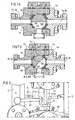
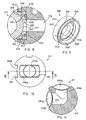
- Fig. 6
- in perspective, a switching ball for the switching device according to the invention according to a second embodiment;
- Fig. 7A, 7B
- based on horizontal sections through the switching device, the switching operation with the switching ball according to the second embodiment;
- Fig. 8
- in a view similar to
Fig. 3 a distribution valve ball with a double-sealing seal body according to a third embodiment; - Fig. 9
- in a perspective view of the seal body in the third embodiment;
- Fig. 10
- the Verteilventilkugel used in the third embodiment in plan view of an orifice; and
- Fig. 11
- a sectional view along XI-XI in
Fig. 10 ,
Der in
Die Zuleitungen für den Fluideinlaß bzw. den Fluidauslaß werden an den in
Die Schaltwelle 21 besteht hier, wie insbesondere aus
Eine wesentliche Funktion der beiden die Verteilventile bildenden Schaltvorrichtungsteile 10A, 10B mit den darin drehbeweglich aufgenommenen Verteilventilkugeln 11A, 11B besteht darin, die jeweils nicht im Betrieb befindliche Filtervorrichtung 3 bzw. 2 vom Fluidstrom abgedichtet abzusperren, so daß die abgesperrte Filtervorrichtung gewartet werden kann. Bei der Wartung kann z.B. ein Filterelement aus der abgesperrten Filtervorrichtung entnommen und durch ein neues Filterelement ersetzt werden. Zum abgedichteten Absperren sind, wie nachfolgend unter Bezugnahme auf die
Ein entsprechendes Dichtungspaar mit Dichtungselementen 30, 40 sowie einem Entlüftungskanal 36, der über eine zweite Stichleitung 37 an ein zweites Nadelventil 52 der Entlüftungsvorrichtung 50 angeschlossen ist, ist auch am gegenüberliegenden Ventilanschluß für die zweite Verbindungsleitung 16 vorgesehen. Im Ausführungsbeispiel gemäß der
Bei beiden Ventilanschlüssen sind die Dichtungselemente 30 sowie 40 vorzugsweise identisch aufgebaut, wobei das erste, unmittelbar an die Verbindungsleitungen 16 angrenzende und diese konzentrisch umgebende Dichtungselement 30 beispielsweise aus PEEK und das zweite, einen größeren Durchmesser aufweisende Dichtungselement 40 beispielsweise aus PTFE mit formbedingter Vorspannung bestehen kann. Durch die formbedingte Vorspannung des zweiten Dichtungselementes 40 und die mittels der beiden O-Ringe 32, 33 aufgebrachte Vorspannung der beiden ersten Dichtungselemente 30 wird gewährleistet, daß auch bei fertigungs- oder montagebedingten Toleranzabweichungen keine der beiden Dichtungen die Dichtwirkung der anderen Dichtung aufheben kann und somit beide Dichtungselemente 30, 40 an jedem Ventilanschluß auch bei geringen Drücken ihre Dichtfunktion erfüllen können. An derjenigen Seite, an der bei einer bestimmten Schaltstellung mittels des Dichtungspaares 30, 40 eine vollständige Abdichtung der Verbindungsleitung 16 bewirkt werden soll, wird mithin jederzeit sichergestellt, daß eine doppelte Abdichtung vorhanden ist. Damit können beide Schaltvorrichtungsteile 10A, 10B zugleich eine Doppelabdichtung bewirken und selbst bei Versagen einer der beiden Dichtungselemente 30 oder 40 wäre immer noch ausreichend Sicherheit gegenüber einem Gasaustritt in die jeweils abgesperrte Verbindungsleitung erreicht. Der Verschmutzungsgrad der Filtervorrichtungen kann hierbei z.B. mittels einer Differenzdruckmeßeinrichtung (nicht dargestellt) überwacht werden, welche an einen in die Kugelaufnahme 12 führenden Anschluß 49 angeschlossen ist. Während des Umschaltvorgangs von der einen in die andere Schaltstellung müssen beide Nadelventile 51, 52 geöffnet sein, während das Bleedventil 53 geschlossen ist. Über die Entlüftungskanäle 34, 36, die Stichleitungen 35, 37 und die Entlüftungsventile 51, 52 kann dann ein Druckausgleich zwischen beiden Filtervorrichtungen 2, 3 stattfinden. Soll eine Wartung der abgesperrten Filtervorrichtung erfolgen, wird dasjenige Entlüftungsventil, welches dem Dichtungspaar für die abgesperrte Filtervorrichtung zugeordnet ist, geöffnet, während das andere Entlüftungsventil geschlossen wird. In den
Die
Die
Für den Fachmann sind aus der vorhergehenden Beschreibung zahlreiche Modifikationen ersichtlich, die in den Schutzbereich der anhängenden Ansprüche fallen sollen. Das einlaßseitige Verteilventil könnte auch unten und das auslaßseitige Verteilventil könnte oben angeordnet sein, wie dies insbesondere bei Gasen üblich ist. Die Gehäuse für die Schaltvorrichtungsteile bzw. Verteilventile könnten auch dreiteilig aufgebaut sein und jede Anschlußleitung wird separat angeflanscht. Bei der entsprechenden Ausgestaltung könnte dann auf beiden Seiten der Verteilventilkugel ein Endstück an den anzubauenden Gehäuseteilen die äußere Dichtung aufnehmen. Die Dichtungselemente auf der einen und auf der anderen Seite könnten auch unterschiedlich gestaltet sein. Das erfindungsgemäß vorgesehene Paar von Dichtungselementen, um bezüglich jedem Ventilausgang bzw. Ventilanschluß eine doppelte Abdichtung zu erreichen, könnte auch bei anderen Schaltvorrichtungen zum Einsatz kommen, bei denen nur einlaßseitig oder nur auslaßseitig ein Verteilventil vorgesehen ist. Solche und weitere Modifikationen sollen in den Schutzbereich der anhängenden Ansprüche fallen.Many modifications will become apparent to those skilled in the art from the foregoing description which are intended to be within the scope of the appended claims. The inlet-side distribution valve could also be down and the outlet-side distribution valve could be arranged on top, as is customary in particular for gases. The housing for the switching device parts or distribution valves could also be constructed in three parts and each lead is flanged separately. In the corresponding embodiment could then take on both sides of the Verteilventilkugel an end piece to be mounted on the housing parts, the outer seal. The sealing elements on one side and on the other side could also be designed differently. The inventively provided pair of sealing elements in order to achieve a double seal with respect to each valve outlet or valve connection, could also be used in other switching devices, in which only on the inlet side or only on the outlet side a distribution valve is provided. Such and other modifications are intended to be within the scope of the appended claims.
Claims (18)
- Switching apparatus for multiple-treatment apparatuses for a fluid flow, in particular for double filters for filtering a fluid flow, having an inlet-side distributor valve (10A), having an outlet-side distributor valve (10B), having in each case one inlet connecting line (15) and one outlet connecting line (16) for each treatment apparatus, which are connected to valve connections of the distributor valves, having a spherical valve body (11A, 11B; 111; 211) which is arranged in the valve housing (13, 14) of each distributor valve, having a switching shaft (21) which connects the valve bodies (11A, 11B) of the inlet-side distributor valve and the outlet-side distributor valve fixedly to one another so as to rotate together for their simultaneous actuation, and having sealing elements which bear against the surface (11', 111'; 211') of the valve bodies for a sealing seat at each valve connection, characterized in that, for sealing with respect to each valve connection, in each case a first sealing element (30; 230) and a separate second sealing element (40; 240) bear against the surface (11', 111'; 211') of the valve body (11A, 11B; 111; 211), between which a ventilating channel (34, 36; 160; 236) is formed which is connected to a ventilating device (50).
- Switching apparatus according to Claim 1, characterized in that at least one of the ventilating channels (34) is formed by a depression or step in the housing (13), which depression or step is formed between the two seals (30, 40) of a seal pair.
- Switching apparatus according to Claim 1 or 2, characterized in that the second sealing element (40) is received at least at one valve connection in an end piece (42) of a housing part (14), which valve connection is connected releasably to a housing part (13) which has a ball receptacle (12) for the valve body (11A, 11B; 111), the ventilating channel (36, 46) being formed in the end piece (42).
- Switching apparatus according to one of Claims 1 to 3, characterized in that the surface (111') of the valve body is provided with at least one circumferential groove (160) on the rear side which faces away from a passage (19) in the valve body (111).
- Switching apparatus according to one of Claims 1 to 4, characterized in that the valve body (111) has a groove (160; 160') for each seal pair, which groove (160; 160') is arranged between the two seals (30, 40) of said seal pair in the switching position of the distributor valve, in which switching position one of the treatment apparatuses is shut off.
- Switching apparatus according to one of Claims 1 to 5, characterized in that two branch lines are formed in the valve housing (13, 14), the first branch line (35) opening into the ventilating channel (34) between the first seal pair and the second branch line (37) opening into the ventilating channel (36) for the second seal pair.
- Switching apparatus according to one of Claims 1 to 6, characterized in that the ventilating device (50) is connected on that side of the distributor-valve housing (13, 14) which lies opposite the inlet connection (8A) and/or outlet connection (8B).
- Switching apparatus according to one of Claims 1 to 7, characterized in that one of the seals, preferably the first seal (30; 230) which is arranged closer to the valve connection, is prestressed towards the surface (11; 211') of the valve body by way of a resilient element, preferably an O-ring (33; 32; 233).
- Switching apparatus according to one of Claims 1 to 8, characterized in that, on account of its shape, the second seal (40) is prestressed towards the surface (11) of the valve body and/or both seals (30, 40) of a seal pair lie in planes which are parallel to one another and are oriented concentrically with respect to the valve connections.
- Switching apparatus according to one of Claims 1 to 9, characterized in that a connecting hole (49) for a differential-pressure measuring device opens into the sealing seat or the valve-body receptacle (12) between the seal pairs.
- Switching apparatus according to one of Claims 1 to 10, characterized in that both sealing elements (230; 240) are formed on a sealing body (280) and preferably comprise separate sealing faces (230', 240') on the sealing body (280), between which sealing faces (230', 240') the ventilating channel (236) is formed.
- Switching apparatus according to Claim 11, characterized in that the sealing body (280) is configured as a ring which has, between the sealing faces (230', 240) which are preferably connected by a base (247), a groove drawn-in section which forms the ventilating channel (236) and into which a plurality of radial holes (249) preferably open.
- Switching apparatus according to one of Claims 1 to 12, characterized in that the passage opening (19) in the valve body (11A, 11B; 111) comprises a slot which extends approximately over one ball half and runs perpendicularly with respect to the rotational axis of the switching shaft (21), the slot (119) preferably having a planar bottom (119') and reaching as far as the ball surface (111).
- Switching apparatus according to one of Claims 1 to 12, characterized in that the spherical valve bodies (211) have an angular, in particular L-shaped passage opening (219), the orifice opening (290A, 290B) of which has a larger cross section on the ball surface (211') than the passage opening (219), the widened portion preferably being formed by means of a slot-like milled-open portion.
- Switching apparatus according to one of Claims 1 to 14, characterized in that a manually actuable switching lever (22) is connected on the switching shaft (21) and/or one or two ventilating valve(s) (51, 52) is/are provided for each distributor valve (10A, 10B).
- Switching apparatus according to one of Claims 1 to 15, characterized by a mechanical switching safety device (6) which prevents unintentional actuation of the switching shaft (21) or of the switching lever (22), the switching safety device (6) preferably having a bolt (7) which interacts with the switching lever (22) and can be pivoted between a locking position and a release position.
- Switching apparatus according to Claim 16, characterized in that the bolt (7) is preloaded or prestressed into the locking position as a result of gravity or by spring force, and/or in that the bolt (7) is mounted pivotably on the treatment apparatuses (2, 3).
- Switching apparatus according to one of Claims 1 to 17, characterized in that a fluid flow connection to one of the treatment apparatuses can be brought about by way of the distributor valve, while the other treatment apparatus is shut off in a manner which is sealed with respect to the fluid flow.
Applications Claiming Priority (1)
| Application Number | Priority Date | Filing Date | Title |
|---|---|---|---|
| DE202005009175U DE202005009175U1 (en) | 2005-06-10 | 2005-06-10 | Switching device for multiple treatment devices |
Publications (3)
| Publication Number | Publication Date |
|---|---|
| EP1731809A2 EP1731809A2 (en) | 2006-12-13 |
| EP1731809A3 EP1731809A3 (en) | 2008-08-20 |
| EP1731809B1 true EP1731809B1 (en) | 2011-03-02 |
Family
ID=36794545
Family Applications (1)
| Application Number | Title | Priority Date | Filing Date |
|---|---|---|---|
| EP06011192A Active EP1731809B1 (en) | 2005-06-10 | 2006-05-31 | Switching mechanism for multiple treatment devices |
Country Status (3)
| Country | Link |
|---|---|
| EP (1) | EP1731809B1 (en) |
| AT (1) | ATE500455T1 (en) |
| DE (2) | DE202005009175U1 (en) |
Families Citing this family (6)
| Publication number | Priority date | Publication date | Assignee | Title |
|---|---|---|---|---|
| DE102009025599B4 (en) | 2009-06-20 | 2019-05-29 | Hansa-Flex Ag | A ball sealing device for sealing against a ball surface of a ball, a tank mixer having such a ball sealing device, and a method of servicing a ball sealing device for sealing against a ball surface of a ball |
| DE102010053411B4 (en) | 2009-12-15 | 2023-07-06 | Vat Holding Ag | vacuum valve |
| DE102010022575A1 (en) * | 2010-06-02 | 2011-12-08 | Hydac Process Technology Gmbh | Switching device for a fluid flow |
| DE102010025153A1 (en) * | 2010-06-25 | 2011-12-29 | Hydac Process Technology Gmbh | Switching device for a fluid flow |
| CN104197037B (en) * | 2014-09-03 | 2016-08-24 | 侯玥 | A kind of combination type multi-station ball-valve |
| CN113531169B (en) * | 2021-07-05 | 2023-03-31 | 浙江天宏特钢有限公司 | Intelligent bidirectional filtering throttling ball valve |
Family Cites Families (4)
| Publication number | Priority date | Publication date | Assignee | Title |
|---|---|---|---|---|
| US3556474A (en) * | 1968-08-19 | 1971-01-19 | Domer Scaramucci | Dual sealed ball valves |
| US4254793A (en) * | 1979-01-15 | 1981-03-10 | Domer Scaramucci | Ball valve having valve chamber venting seal assemblies |
| JPS58131477A (en) * | 1983-01-17 | 1983-08-05 | Kobe Steel Ltd | Valve |
| NL1013330C2 (en) | 1999-10-18 | 2001-04-19 | Indufil B V | Switching device and medium flow optionally through a first or second treatment member. |
-
2005
- 2005-06-10 DE DE202005009175U patent/DE202005009175U1/en not_active Expired - Lifetime
-
2006
- 2006-05-31 EP EP06011192A patent/EP1731809B1/en active Active
- 2006-05-31 AT AT06011192T patent/ATE500455T1/en active
- 2006-05-31 DE DE502006008975T patent/DE502006008975D1/en active Active
Also Published As
| Publication number | Publication date |
|---|---|
| EP1731809A2 (en) | 2006-12-13 |
| EP1731809A3 (en) | 2008-08-20 |
| DE502006008975D1 (en) | 2011-04-14 |
| ATE500455T1 (en) | 2011-03-15 |
| DE202005009175U1 (en) | 2006-07-27 |
Similar Documents
| Publication | Publication Date | Title |
|---|---|---|
| EP1731809B1 (en) | Switching mechanism for multiple treatment devices | |
| DE102005031962B4 (en) | Multi-way valve | |
| DE112014003555T5 (en) | Quick-release valve for rail vehicles and piping system of a rail vehicle | |
| EP1991807A1 (en) | Multicoupling device | |
| DE60128717T2 (en) | FOUR WAY VALVE | |
| DE202006002375U1 (en) | Ball valve has groove with sloping base on outer surface of ball which connects one of fluid channels with vent at right angles to it when valve is closed | |
| EP3037699B1 (en) | Mixer valve | |
| DE102014009231B4 (en) | Shut-off filter apparatus | |
| EP0310841B1 (en) | 3-way armature | |
| EP0176828B1 (en) | Oil-sealed vacuum pump | |
| EP2423555B1 (en) | Coupling assembly | |
| DE10324874B3 (en) | Valve, in particular steam valve | |
| EP2352938B1 (en) | Disk valve with leak prevention | |
| EP1468220A1 (en) | Fitting | |
| WO2011151023A1 (en) | Switching device for conducting a fluid | |
| DE202011102932U1 (en) | Frost-resistant outside wall valve for low temperatures | |
| WO2015117767A1 (en) | Fitting having a pivoting outlet | |
| EP4083480A2 (en) | Fluid valve assembly | |
| WO2021254718A1 (en) | Venting device | |
| WO2021073884A1 (en) | Fluid valve | |
| DE10039496C2 (en) | Connection adapter for water pipes with bypass | |
| DE202005009176U1 (en) | Switch device consists of split valves on inlet and outlet side switch devices connected to inlet and outlet connection channels that are sealed at the exits and arranged about an axle that operates a switch shaft | |
| DE602004002339T2 (en) | Valve | |
| EP1340933B1 (en) | High pressure valve | |
| EP3947973B1 (en) | Lubricant receptacle |
Legal Events
| Date | Code | Title | Description |
|---|---|---|---|
| PUAI | Public reference made under article 153(3) epc to a published international application that has entered the european phase |
Free format text: ORIGINAL CODE: 0009012 |
|
| AK | Designated contracting states |
Kind code of ref document: A2 Designated state(s): AT BE BG CH CY CZ DE DK EE ES FI FR GB GR HU IE IS IT LI LT LU LV MC NL PL PT RO SE SI SK TR |
|
| AX | Request for extension of the european patent |
Extension state: AL BA HR MK YU |
|
| PUAL | Search report despatched |
Free format text: ORIGINAL CODE: 0009013 |
|
| AK | Designated contracting states |
Kind code of ref document: A3 Designated state(s): AT BE BG CH CY CZ DE DK EE ES FI FR GB GR HU IE IS IT LI LT LU LV MC NL PL PT RO SE SI SK TR |
|
| AX | Request for extension of the european patent |
Extension state: AL BA HR MK YU |
|
| RIC1 | Information provided on ipc code assigned before grant |
Ipc: F16K 11/16 20060101AFI20060908BHEP Ipc: F16K 35/14 20060101ALI20080711BHEP Ipc: F16K 5/06 20060101ALI20080711BHEP Ipc: B01D 35/00 20060101ALI20080711BHEP |
|
| 17P | Request for examination filed |
Effective date: 20090204 |
|
| 17Q | First examination report despatched |
Effective date: 20090313 |
|
| AKX | Designation fees paid |
Designated state(s): AT BE BG CH CY CZ DE DK EE ES FI FR GB GR HU IE IS IT LI LT LU LV MC NL PL PT RO SE SI SK TR |
|
| GRAP | Despatch of communication of intention to grant a patent |
Free format text: ORIGINAL CODE: EPIDOSNIGR1 |
|
| GRAS | Grant fee paid |
Free format text: ORIGINAL CODE: EPIDOSNIGR3 |
|
| GRAA | (expected) grant |
Free format text: ORIGINAL CODE: 0009210 |
|
| AK | Designated contracting states |
Kind code of ref document: B1 Designated state(s): AT BE BG CH CY CZ DE DK EE ES FI FR GB GR HU IE IS IT LI LT LU LV MC NL PL PT RO SE SI SK TR |
|
| REG | Reference to a national code |
Ref country code: GB Ref legal event code: FG4D Free format text: NOT ENGLISH |
|
| REG | Reference to a national code |
Ref country code: CH Ref legal event code: EP |
|
| REG | Reference to a national code |
Ref country code: IE Ref legal event code: FG4D Free format text: LANGUAGE OF EP DOCUMENT: GERMAN |
|
| REF | Corresponds to: |
Ref document number: 502006008975 Country of ref document: DE Date of ref document: 20110414 Kind code of ref document: P |
|
| REG | Reference to a national code |
Ref country code: DE Ref legal event code: R096 Ref document number: 502006008975 Country of ref document: DE Effective date: 20110414 |
|
| REG | Reference to a national code |
Ref country code: NL Ref legal event code: T3 |
|
| PG25 | Lapsed in a contracting state [announced via postgrant information from national office to epo] |
Ref country code: LT Free format text: LAPSE BECAUSE OF FAILURE TO SUBMIT A TRANSLATION OF THE DESCRIPTION OR TO PAY THE FEE WITHIN THE PRESCRIBED TIME-LIMIT Effective date: 20110302 Ref country code: GR Free format text: LAPSE BECAUSE OF FAILURE TO SUBMIT A TRANSLATION OF THE DESCRIPTION OR TO PAY THE FEE WITHIN THE PRESCRIBED TIME-LIMIT Effective date: 20110603 Ref country code: SE Free format text: LAPSE BECAUSE OF FAILURE TO SUBMIT A TRANSLATION OF THE DESCRIPTION OR TO PAY THE FEE WITHIN THE PRESCRIBED TIME-LIMIT Effective date: 20110302 Ref country code: ES Free format text: LAPSE BECAUSE OF FAILURE TO SUBMIT A TRANSLATION OF THE DESCRIPTION OR TO PAY THE FEE WITHIN THE PRESCRIBED TIME-LIMIT Effective date: 20110613 Ref country code: LV Free format text: LAPSE BECAUSE OF FAILURE TO SUBMIT A TRANSLATION OF THE DESCRIPTION OR TO PAY THE FEE WITHIN THE PRESCRIBED TIME-LIMIT Effective date: 20110302 |
|
| LTIE | Lt: invalidation of european patent or patent extension |
Effective date: 20110302 |
|
| PG25 | Lapsed in a contracting state [announced via postgrant information from national office to epo] |
Ref country code: BG Free format text: LAPSE BECAUSE OF FAILURE TO SUBMIT A TRANSLATION OF THE DESCRIPTION OR TO PAY THE FEE WITHIN THE PRESCRIBED TIME-LIMIT Effective date: 20110602 Ref country code: FI Free format text: LAPSE BECAUSE OF FAILURE TO SUBMIT A TRANSLATION OF THE DESCRIPTION OR TO PAY THE FEE WITHIN THE PRESCRIBED TIME-LIMIT Effective date: 20110302 Ref country code: CY Free format text: LAPSE BECAUSE OF FAILURE TO SUBMIT A TRANSLATION OF THE DESCRIPTION OR TO PAY THE FEE WITHIN THE PRESCRIBED TIME-LIMIT Effective date: 20110302 Ref country code: SI Free format text: LAPSE BECAUSE OF FAILURE TO SUBMIT A TRANSLATION OF THE DESCRIPTION OR TO PAY THE FEE WITHIN THE PRESCRIBED TIME-LIMIT Effective date: 20110302 |
|
| REG | Reference to a national code |
Ref country code: IE Ref legal event code: FD4D |
|
| PG25 | Lapsed in a contracting state [announced via postgrant information from national office to epo] |
Ref country code: EE Free format text: LAPSE BECAUSE OF FAILURE TO SUBMIT A TRANSLATION OF THE DESCRIPTION OR TO PAY THE FEE WITHIN THE PRESCRIBED TIME-LIMIT Effective date: 20110302 Ref country code: IE Free format text: LAPSE BECAUSE OF FAILURE TO SUBMIT A TRANSLATION OF THE DESCRIPTION OR TO PAY THE FEE WITHIN THE PRESCRIBED TIME-LIMIT Effective date: 20110302 Ref country code: PT Free format text: LAPSE BECAUSE OF FAILURE TO SUBMIT A TRANSLATION OF THE DESCRIPTION OR TO PAY THE FEE WITHIN THE PRESCRIBED TIME-LIMIT Effective date: 20110704 |
|
| BERE | Be: lapsed |
Owner name: BOLL & KIRCH FILTERBAU G.M.B.H. Effective date: 20110531 |
|
| PG25 | Lapsed in a contracting state [announced via postgrant information from national office to epo] |
Ref country code: IS Free format text: LAPSE BECAUSE OF FAILURE TO SUBMIT A TRANSLATION OF THE DESCRIPTION OR TO PAY THE FEE WITHIN THE PRESCRIBED TIME-LIMIT Effective date: 20110702 Ref country code: SK Free format text: LAPSE BECAUSE OF FAILURE TO SUBMIT A TRANSLATION OF THE DESCRIPTION OR TO PAY THE FEE WITHIN THE PRESCRIBED TIME-LIMIT Effective date: 20110302 Ref country code: CZ Free format text: LAPSE BECAUSE OF FAILURE TO SUBMIT A TRANSLATION OF THE DESCRIPTION OR TO PAY THE FEE WITHIN THE PRESCRIBED TIME-LIMIT Effective date: 20110302 Ref country code: RO Free format text: LAPSE BECAUSE OF FAILURE TO SUBMIT A TRANSLATION OF THE DESCRIPTION OR TO PAY THE FEE WITHIN THE PRESCRIBED TIME-LIMIT Effective date: 20110302 |
|
| PG25 | Lapsed in a contracting state [announced via postgrant information from national office to epo] |
Ref country code: MC Free format text: LAPSE BECAUSE OF NON-PAYMENT OF DUE FEES Effective date: 20110531 |
|
| PLBE | No opposition filed within time limit |
Free format text: ORIGINAL CODE: 0009261 |
|
| STAA | Information on the status of an ep patent application or granted ep patent |
Free format text: STATUS: NO OPPOSITION FILED WITHIN TIME LIMIT |
|
| 26N | No opposition filed |
Effective date: 20111205 |
|
| PG25 | Lapsed in a contracting state [announced via postgrant information from national office to epo] |
Ref country code: DK Free format text: LAPSE BECAUSE OF FAILURE TO SUBMIT A TRANSLATION OF THE DESCRIPTION OR TO PAY THE FEE WITHIN THE PRESCRIBED TIME-LIMIT Effective date: 20110302 Ref country code: PL Free format text: LAPSE BECAUSE OF FAILURE TO SUBMIT A TRANSLATION OF THE DESCRIPTION OR TO PAY THE FEE WITHIN THE PRESCRIBED TIME-LIMIT Effective date: 20110302 |
|
| REG | Reference to a national code |
Ref country code: DE Ref legal event code: R097 Ref document number: 502006008975 Country of ref document: DE Effective date: 20111205 |
|
| PG25 | Lapsed in a contracting state [announced via postgrant information from national office to epo] |
Ref country code: BE Free format text: LAPSE BECAUSE OF NON-PAYMENT OF DUE FEES Effective date: 20110531 |
|
| REG | Reference to a national code |
Ref country code: AT Ref legal event code: MM01 Ref document number: 500455 Country of ref document: AT Kind code of ref document: T Effective date: 20110531 |
|
| PG25 | Lapsed in a contracting state [announced via postgrant information from national office to epo] |
Ref country code: AT Free format text: LAPSE BECAUSE OF NON-PAYMENT OF DUE FEES Effective date: 20110531 |
|
| PG25 | Lapsed in a contracting state [announced via postgrant information from national office to epo] |
Ref country code: LU Free format text: LAPSE BECAUSE OF NON-PAYMENT OF DUE FEES Effective date: 20110531 |
|
| PG25 | Lapsed in a contracting state [announced via postgrant information from national office to epo] |
Ref country code: TR Free format text: LAPSE BECAUSE OF FAILURE TO SUBMIT A TRANSLATION OF THE DESCRIPTION OR TO PAY THE FEE WITHIN THE PRESCRIBED TIME-LIMIT Effective date: 20110302 |
|
| PG25 | Lapsed in a contracting state [announced via postgrant information from national office to epo] |
Ref country code: HU Free format text: LAPSE BECAUSE OF FAILURE TO SUBMIT A TRANSLATION OF THE DESCRIPTION OR TO PAY THE FEE WITHIN THE PRESCRIBED TIME-LIMIT Effective date: 20110302 |
|
| REG | Reference to a national code |
Ref country code: FR Ref legal event code: PLFP Year of fee payment: 11 |
|
| REG | Reference to a national code |
Ref country code: FR Ref legal event code: PLFP Year of fee payment: 12 |
|
| REG | Reference to a national code |
Ref country code: FR Ref legal event code: PLFP Year of fee payment: 13 |
|
| REG | Reference to a national code |
Ref country code: DE Ref legal event code: R082 Ref document number: 502006008975 Country of ref document: DE Representative=s name: BUSCHHOFF-HENNICKE-ALTHAUS, DE Ref country code: DE Ref legal event code: R081 Ref document number: 502006008975 Country of ref document: DE Owner name: BOLL & KIRCH FILTERBAU GESELLSCHAFT MIT BESCHR, DE Free format text: FORMER OWNER: BOLL & KIRCH FILTERBAU GMBH, 50170 KERPEN, DE |
|
| PGFP | Annual fee paid to national office [announced via postgrant information from national office to epo] |
Ref country code: NL Payment date: 20230519 Year of fee payment: 18 Ref country code: IT Payment date: 20230531 Year of fee payment: 18 Ref country code: FR Payment date: 20230517 Year of fee payment: 18 Ref country code: DE Payment date: 20230426 Year of fee payment: 18 Ref country code: CH Payment date: 20230605 Year of fee payment: 18 |
|
| PGFP | Annual fee paid to national office [announced via postgrant information from national office to epo] |
Ref country code: GB Payment date: 20230522 Year of fee payment: 18 |