EP1731403A2 - Steering apparatus for a vehicle - Google Patents
Steering apparatus for a vehicle Download PDFInfo
- Publication number
- EP1731403A2 EP1731403A2 EP06252948A EP06252948A EP1731403A2 EP 1731403 A2 EP1731403 A2 EP 1731403A2 EP 06252948 A EP06252948 A EP 06252948A EP 06252948 A EP06252948 A EP 06252948A EP 1731403 A2 EP1731403 A2 EP 1731403A2
- Authority
- EP
- European Patent Office
- Prior art keywords
- steering
- unit
- clutch
- vehicle
- rotation
- Prior art date
- Legal status (The legal status is an assumption and is not a legal conclusion. Google has not performed a legal analysis and makes no representation as to the accuracy of the status listed.)
- Granted
Links
Images


Classifications
-
- B—PERFORMING OPERATIONS; TRANSPORTING
- B62—LAND VEHICLES FOR TRAVELLING OTHERWISE THAN ON RAILS
- B62D—MOTOR VEHICLES; TRAILERS
- B62D5/00—Power-assisted or power-driven steering
- B62D5/04—Power-assisted or power-driven steering electrical, e.g. using an electric servo-motor connected to, or forming part of, the steering gear
- B62D5/0409—Electric motor acting on the steering column
-
- B—PERFORMING OPERATIONS; TRANSPORTING
- B62—LAND VEHICLES FOR TRAVELLING OTHERWISE THAN ON RAILS
- B62D—MOTOR VEHICLES; TRAILERS
- B62D1/00—Steering controls, i.e. means for initiating a change of direction of the vehicle
- B62D1/02—Steering controls, i.e. means for initiating a change of direction of the vehicle vehicle-mounted
- B62D1/16—Steering columns
- B62D1/163—Part of the steering column replaced by flexible means, e.g. cable or belt
-
- B—PERFORMING OPERATIONS; TRANSPORTING
- B62—LAND VEHICLES FOR TRAVELLING OTHERWISE THAN ON RAILS
- B62D—MOTOR VEHICLES; TRAILERS
- B62D5/00—Power-assisted or power-driven steering
- B62D5/001—Mechanical components or aspects of steer-by-wire systems, not otherwise provided for in this maingroup
- B62D5/003—Backup systems, e.g. for manual steering
-
- B—PERFORMING OPERATIONS; TRANSPORTING
- B62—LAND VEHICLES FOR TRAVELLING OTHERWISE THAN ON RAILS
- B62D—MOTOR VEHICLES; TRAILERS
- B62D5/00—Power-assisted or power-driven steering
- B62D5/001—Mechanical components or aspects of steer-by-wire systems, not otherwise provided for in this maingroup
- B62D5/005—Mechanical components or aspects of steer-by-wire systems, not otherwise provided for in this maingroup means for generating torque on steering wheel or input member, e.g. feedback
- B62D5/006—Mechanical components or aspects of steer-by-wire systems, not otherwise provided for in this maingroup means for generating torque on steering wheel or input member, e.g. feedback power actuated
Definitions
- the present invention relates to a steering apparatus for a vehicle.
- the invention also relates to a vehicle equipped with such an apparatus.
- a column shaft connected to a steering wheel is connected to a reaction motor, a clutch and a steering wheel side cable pulley of a backup means as described in, for example, Japanese Laid Open Patent Application No. 2002-225733 .
- one end of a first cable is connected to the steering wheel, and one end of a second cable is connected to a gear box.
- the other end of the first cable and the other end of the second cable are connected with an intermediate interlocking means provided between the steering wheel and the gear box.
- Japanese Laid Open Published Patent Application No. H10-67327 see Japanese Laid Open Published Patent Application No. H10-67327 .
- a steering apparatus for a vehicle comprising a steering unit having an operational input unit and a reaction generating unit, a steered unit that is mechanically separated from the steering unit and that steers steering controlled wheels, a clutch that is provided between the steering unit and steered unit, a backup unit that is provided between the clutch and the steered unit and transmits a steering torque that is inputted from the operational input unit, when the clutch is engaged, to the steering controlled wheels, and a first rotation conversion unit provided between the reaction generating unit and the clutch, for changing a rotation axis direction of the operational input unit.
- the first rotation conversion unit changes the rotation axis direction by about 90 degrees.
- the first rotation conversion unit outputs a rotation of the operational input unit towards the outside of the vehicle in a width direction of the vehicle.
- the first rotation conversion unit outputs a rotation of the operational input unit towards the inside of the vehicle in a width direction of the vehicle.
- the first rotation conversion unit outputs a rotation of the operational input unit in a downward direction of the vehicle.
- the backup unit comprises a cable-type column
- the clutch transmits the rotation outputted from the first rotation conversion unit to the cable-type column when the clutch is engaged.
- the apparatus may comprise a shaft that connects the first rotation conversion unit to the clutch wherein the shaft has a joint in which a connection thereof comes apart when a load is applied to the joint in a direction perpendicular to an axis direction of the shaft.
- the apparatus may comprise a second rotation conversion unit provided between the first rotation conversion unit and the steered unit that changes the rotation axis direction of the first rotation conversion unit towards the steered unit.
- the clutch is provided between the first rotation conversion unit and the second rotation conversion unit.
- the first rotation conversion unit further comprises a speed increasing unit that increases a rotation to be inputted to the clutch.
- the second rotation conversion unit includes a speed decreasing unit that decreases a rotation to be inputted to the clutch.
- the speed decreasing unit connects the backup unit and the steered unit.
- the speed decreasing unit is a steering gear of the steered unit.
- the apparatus may comprise a bulkhead that divides a cabin space and an outside of the cabin space, wherein the steering unit is provided in the cabin space, and the steered unit is provided outside of the cabin space, and the first and second rotation conversion units are provided on a steering unit side of the bulkhead and the backup unit is provided on a steered unit side of the bulkhead.
- the backup unit is a cable-type column, and a steering unit side pulley case of the cable-type column contains a steering unit side pulley and is fixed to the bulkhead.
- the second rotation conversion unit is fixed to the steering unit side pulley case.
- the clutch is provided between the second rotation conversion unit and the steering unit side pulley.
- the clutch is provided on the steering unit side of the bulkhead.
- the clutch is fixed to the steering unit side pulley case.
- the clutch is provided on the steered unit side of the bulkhead.
- the apparatus may comprise a bulkhead that divides a cabin space and an outside of the cabin space, wherein the steering unit is provided in the cabin space, and the steered unit is provided outside of the cabin space, and the first rotation conversion unit changes the rotation axis direction of the operational input unit towards a direction along the bulkhead.
- the steering unit provided in the cabin space, and the first rotation conversion units changes the rotation axis direction to reduce the length of the steering unit in the axis direction in the cabin space.
- a rotation axis direction of a steering unit is changed to a different direction by a rotation direction conversion unit before the rotation transmitted from the steering unit is transmitted to a clutch, so that the length of the steering unit may be shortened.
- a steering apparatus for a vehicle may be reduced in size in the axis direction of the steering unit so that superior vehicle mountability may be obtained.
- FIG. 1 is a schematic view of an overview structure of a steer-by-wire system to which a vehicle steering apparatus according to Embodiment 1 is applied.
- the vehicle steering apparatus comprises a steering unit A, a cable-type column 10, a steered unit B, and a controller 19, each of which will be described below.
- the steering unit A comprises a steering wheel operation input unit 1, a column shaft 2, a reaction motor (reaction actuator) 3, a bevel gear (a rotation direction conversion unit) 4, a clutch 6, a steering wheel angle sensor 13, and a resolver 15.
- the reaction motor 3 is a coaxial motor, whose output axis is coaxial with the column shaft 2, and outputs a steering reaction torque to the column shaft 2, which simulates a road surface reaction according to a command current value from the controller 19.
- the bevel gear 4 is provided between the reaction motor 3 and the clutch 6, and changes the rotation axis direction of the steering wheel 1 (axis direction of the column shaft 2) so as to be different from the rotation axis direction of the clutch 6.
- the clutch 6 is provided between the column shaft 2 and the cable-type column 10.
- an electromagnetic clutch is used.
- the steering torque applied to the steering wheel 1 is mechanically transmitted to the steering mechanism 11.
- the steering wheel angle sensor 13 detects the rotation angle of the column shaft 2.
- the resolver 15 detects the rotation angle of the reaction motor 3.
- the cable-type column 10 is a mechanical backup mechanism that carries out a column shaft function for transmitting a torque in a backup mode in which the clutch 6 is engaged, and is diverted so as not to interference with members that exist between the steering unit A and the steered unit B.
- the cable-type column 10 is structured such that two inner cables are wound around the steering wheel side cable reel 10a that is connected to the column shaft 2, and a pinion side cable reel 10b that is connected to a pinion shaft 21, in opposite directions to each other. The ends of these two inner cables are fixed to cable reels 10a and 10b, respectively and both sides of outer tubes 10c and 10c in which the two inner cables are inserted are fixed to these two reel cases.
- the steered unit B comprises a steering mechanism 11, a resolver 16, a torque sensor 17, an encoder 18, steered side motors 20 and 20, a pinion shaft 21 and steering controlled wheels 22 and 22.
- the steering mechanism 11 has a rack and pinion-type steering gear and steers the steering controlled wheels 22 and 22 in correspondence with the rotation of the pinion shaft 21.
- the steered side motors 20 and 20 are connected to the pinion shaft 21 via an attenuator such as a worm and worm wheels, etc, and outputs the steered torque for steering the steering controlled wheels 22 and 22, to the pinion shaft 21 in correspondence with the command current value from the controller 19.
- the resolver 16 detects the motor rotation angle of the steered side motors 20 and 20.
- the torque sensor 17 detects the input torque to the pinion shaft 21.
- the encoder 18 detects the rotation angle of the pinion shaft 21.
- Information detected by the steering wheel angle sensor 13, a torque sensor 14, the resolvers 15 and 16, the torque sensor 17 and the encoder 18 is inputted to the controller 19, so as to drive and control the reaction motor 3 and the steered side motors 20 and 20 based on each of the sensor signals.
- the steering wheel angle sensor 13 detects the rotation angle of the steering wheel 1, and based on the detected rotation angle, the controller 19 calculates the steering amount of the steering gear 11, and the controller 19 outputs the command current value for driving the steered unit side motors 20 and 20, so that the steering mechanism 11 is driven.
- the torque sensor 17 detects the reaction force that is applied to the steering mechanism 11 and the command current value for driving the reaction motor 3 is outputted from the controller 19, so that the steering reaction force is applied to the steering wheel 1.
- the clutch 6 is engaged so as to mechanically connect the steering wheel 1 to the steering mechanism 11. At this time, the operation force of the steering wheel 1 is transmitted from the steering wheel 1, to the column shaft 2, the bevel gear 4, the clutch 6, the cable-type column 10 and the steering mechanism 11.
- FIG. 2 shows the steering unit A according to Embodiment 1.
- the steering unit A is provided inside a cabin space (a vehicle interior for a driver to drive the vehicle) which is sectioned from the front body (e.g., engine room) by a dash panel (bulkhead) 9.
- the bevel gear 4 and the clutch 6 are connected by a first shaft 5, and the clutch 6 and the steering wheel side cable reel 10a are connected by a second shaft 7. Because of the bevel gear 4, the direction of the rotation axis m of the steering wheel 1, the column shaft 2 and the reaction motor 3 is perpendicular to the rotation axis n of the first shaft 5, clutch 6 and the second shaft 7.
- the bevel gear 4 changes the rotation axis direction of the steering wheel 1 towards a direction along the dash panel 9.
- the angle formed by the direction of the rotation axis m and the direction of the rotation axis n is not limited to 90 degrees but may be greater to or less than 90 degrees.
- FIG. 3 is a cross-sectional view of the first bevel gear 4.
- the first bevel gear 4 comprises an input shaft 4c and an output shaft 4d. One end of the input shaft 4c is connected to the column shaft 2, and the other end thereof is connected to the input gear 4a. One end of the output shaft 4d is connected to the output gear 4b and the other end thereof is connected to the first shaft 5.
- the input and output gears 4a and 4b are contained in a casing 4e.
- the input shaft 4c is supported by the casing 4e via two needle bearings 4f and 4g
- the output shaft 4d is supported by the casing 4e via two needle bearings 4h and 4i and a ball bearing 4j.
- the size in the axis direction of the apparatus is reduced by converting the rotation axis direction. Description thereof will be given below.
- FIG. 4 shows a steering unit of a conventional steer-by-wire system.
- a reaction motor, a clutch and a steering wheel side cable reel of the cable-type column are provided in series, in other words, coaxially on the axis of the column shaft that is connected to the steering wheel, the length in the axis direction L0 becomes necessarily long.
- the length of the steering unit in the axis direction be as short as possible.
- the bevel gear 4 that changes the direction of the rotation axis n of the clutch 6 is provided, so that the direction of rotational axis n of the clutch 6 is perpendicular to the direction of the rotation axis m of the steering wheel 1, the length L1 (FIG. 2) in the axis direction can be set shorter than the length L0 in the axis direction of the above-mentioned prior art. Consequently, the vehicle mountability can be improved and the freedom of the cabin space layout can be increased.
- the vehicle steering apparatus according to Embodiment 1 has advantages set forth below.
- the steering unit A having the steering wheel 1 and the reaction motor 3, and the steered unit B that steers the steering controlled wheels 22 and 22 can be mechanically separated from each other, but, the steering apparatus for a vehicle has the clutch 6 that can mechanically connect the steering unit A and the steered unit B.
- the backup unit (cable-type column 10) is provided between the clutch 6 and the steered unit B and transmits the steering torque inputted from the steering wheel 1 to the steering controlled wheels 22 and 22 when the clutch 6 is engaged.
- the bevel gear 4 that changes from the rotation axis direction of the steering wheel 1 to the rotation axis direction of the clutch 6 is provided between the reaction motor 3 and the clutch 6.
- the clutch 6 on the rotation axis of the steering wheel 1 is not needed thereby reducing the length L1 in the axis direction of the steering unit A, so that the vehicle mountability can be improved compared to the prior art.
- the bevel gear 4 is provided on the side of the steering controlled wheels 22 and 22 from the reaction motor 3 thereby preventing the discomfort of steering due to the friction, etc., by the bevel gear 4.
- the bevel gear 4 generates an output in the rotation axis direction of the clutch 6 at an approximate right angle relative to the rotation axis direction of the steering wheel 1, and therefore the freedom of layout can be increased thereby reducing the length of the steering unit A in the axis direction to the minimum.
- the backup unit comprises the cable-type column 10
- the clutch 6 transmits the rotation generated by the steering wheel 1 to the cable-type column 10 when the clutch 6 is engaged, the column shaft 2 can be prevented from moving into the cabin space upon a vehicle collision.
- the reaction motor 3 comprises a coaxial motor whose output shaft is coaxially provided with the column shaft 2 and therefore, the length of the column shaft 2 in the diameter direction can be reduced and also a high output motor can be used.
- the length L1 in the axis direction can be shorter than in case where the output shaft of a motor is connected to the column shaft 2 via a worm & worm wheel, thereby increasing the freedom of layout.
- FIG. 5 is a schematic view of a steer-by-wire system in which a steering apparatus for vehicle according to Embodiment 2 is applied.
- a bevel gear 4 according to Embodiment 2 is provided so that rotation of the steering wheel 1 is outputted in a width direction of the vehicle towards the outside of the vehicle.
- a communication hole 9a that allows the outer tubes 10c and 10c of the cable-type column 10 come out of the cabin space is formed on the outside portion of the dash panel 9 in the vehicle width direction.
- the outer tubes 10c and 10c of the cable-type column 10 can be rerouted, on a side portion of the vehicle so as not to easily intervene with the engine room members.
- the vehicle steering apparatus according to Embodiment 2 has advantages set forth below, in addition to the advantages (1) to (4) of Embodiment 1 described above.
- the outer tubes 10c and 10c of the cable-type column 10 can be led on the side portion of the vehicle when they are led from the inside to the outside of the cabin space, thereby easily avoiding any intervention with the engine room members.
- FIG. 6 is a schematic view of a steer-by-wire system in which a steering apparatus for a vehicle according to Embodiment 3 is applied.
- the bevel gear 4 according to Embodiment 3 is provided so that the rotation of the steering wheel 1 is outputted towards the inside of the vehicle in a width direction of the vehicle.
- a communication hole 9b that allows the outer tubes 10c and 10c of the cable-type column to come out of the cabin space is formed at an approximate center position of the dash panel 9 in the width direction of the vehicle.
- the communication hole 9a is formed on the outside portion of the dash panel 9 in the width direction of the vehicle, and therefore a two types of dash panels have to be prepared for a right-hand steering wheel vehicle and a left-hand steering wheel vehicle. Nonetheless, according to Embodiment 3, the communication hole 9b is formed at the approximate center location of the dash panel 9 in the width direction of the vehicle so that the dash panel 9 can be shared by both a right-hand steering wheel vehicle and a left-hand steering wheel vehicle thereby allowing a cost reduction.
- the vehicle steering apparatus according to Embodiment 3 has advantages set forth below, in addition to the advantages (1) to (4) of Embodiment 1 described above.
- the communication hole 9b provided at the approximate center of the dash panel 9 can be shared by both the left-hand and right-hand steering wheel vehicle.
- FIG. 7 is a schematic view of a steer-by-wire system in which a steering apparatus for a vehicle according to Embodiment 4 is employed.
- the bevel gear 4 is arranged so as to output the rotation of the steering wheel 1 in a downward direction of the vehicle.
- the bevel gear 4 outputs the rotation of the steering wheel 1 in the downward direction of the vehicle so that the outer tubes 10c and 10c of the cable-type column 10 can be rerouted on the bottom portion of the vehicle so as not to interfere with the engine room members.
- the vehicle steering apparatus according to Embodiment 4 has advantages set forth below, in addition to the advantages (1) to (4) according to Embodiment 1.
- the outer tubes 10c and 10c of the cable-type column 10 can be led on the bottom of the vehicle when they are led from the inside to the outside of the cabin space, thereby easily avoiding interference with the engine room members.
- FIGS. 8A, 8B and 8C show the structure of a first shaft 5 according to Embodiment 5 in which the first shaft 5 connects the bevel gear 4 and clutch 6.
- the first shaft 5 comprises two members 23 and 24 provided in the lengthwise direction, and a joint 25 formed by connecting surfaces of these two members 23 and 24, in which the joint of the two members 23 and 24 are disengaged when a load F in a direction perpendicular to the axis direction is applied.
- concave portions 23a are formed on the member 23 and corresponding convex portions 24a that engage with the concave portions 23a are formed on the member 24.
- the concave portions 23a and the convex portions 24a that form a mating structure are disengaged when a load F in the direction perpendicular to the axis direction is applied.
- the vehicle steering apparatus according to Embodiment 5 has advantages set forth below, in addition to the advantages (1) to (4) of Embodiment 1.
- the first shaft 5 connects the bevel gear 4 to the clutch 6, and the first shaft 5 has the joint 25 at which the two members 23 and 24 are disengaged when the first shaft 5 receives a load from a direction intersecting with the axis direction, and a load F in the direction perpendicular to the axis direction is applied, and therefore the impact on the driver can be reduced during a vehicle collision.
- the joint 25 has the mating structure in which the two members 23 and 24 are disengaged when a load F in the direction perpendicular to the axis direction is applied and therefore it breaks only upon collision and the steering power can be securely transmitted to the steering controlled wheels 22 and 22 during the backup mode.
- the member 23 Since at the joint 25, the member 23 has the concave shape 23a and the member 24 has corresponding convex shape 24a that engages with the concave shape 23a, the joint that breaks upon collision can be constructed with a simple structure.
- FIG. 9 shows the structure of a first shaft 5 according to Embodiment 6.
- the first shaft 5 comprises a joint 26 in which small diameter portions 26a and large diameter portions 26b are provided in alternation, and this joint 26 is designed so that the small diameter portions 26a will break when a load F is applied in the direction perpendicular to the axis direction.
- Embodiment 6 Since an operation of Embodiment 6 is the same as that of Embodiment 5, the description is omitted.
- the vehicle steering apparatus according to Embodiment 6 has advantages set forth below, in addition to the advantages (1) to (4) of Embodiment 1.
- the joint 26 has a shape by which it folds when a load F in the direction perpendicular to the axis is applied, and therefore the impact on the driver can be reduced during a vehicle collision.
- FIGS. 10A, 10B and 10C show the structure of a first shaft 5 according to Embodiment 7.
- the first shaft 5 comprises two members 27 and 28 in a longitudinal direction, and a joint 29 at which the joint of the two members 27 and 28 are disengaged when a load F in the direction perpendicular to the axis of the members direction is applied.
- the member 27 has an open shape 27a, which is a cross shaped recess, and a cross shaped projection 28a that generally corresponds to the open shape 27a is formed on the side of the member 28.
- This joint 29 has a mating structure in which the open shape 27a and the cross-shaped projection 28a are disengaged when a load F in the perpendicular direction is applied.
- Embodiment 7 is the same as that of Embodiment 5 and therefore the description thereof is omitted.
- the vehicle steering apparatus according to Embodiment 7 has advantages set forth below, in addition to the advantages (1) to (4) of Embodiment 1, and the advantage (8) of Embodiment 5.
- the joint that breaks upon collision can be constructed with a simple structure.
- FIG. 11 is a schematic view of a steer-by-wire system to which a steering apparatus for a vehicle according to Embodiment 8 is employed.
- Embodiment 8 comprises a projection 30 that promotes a break by coming into contact with the joint portion 25 when the steering unit A moves towards the front of the vehicle body, and which is provided on the dash panel 9 facing the joint 25.
- Embodiment 8 dismantling of the steering unit upon a collision is promoted.
- the steering unit A moves towards the dash panel 9 and comes in contact with the projection 30 that is provided on the dash panel 9 and therefore the first shaft 5 is securely broken by the contact with the projection 30 so that the steering unit A can be dismantled.
- the vehicle steering apparatus according to Embodiment 8 has advantages set forth below, in addition to the advantages (1) to (4) of Embodiment 1, and the advantage (8) of Embodiment 5.
- the projection 30 is provided on the dash panel 9 of the vehicle so as to face the joint 25, when the steering unit A comes close to the dash panel 9 upon a vehicle collision, it securely comes in contact with the first shaft 5 to break the first shaft 5, so that the steering unit A can be dismantled.
- FIG. 12 is a schematic view of a steer-by-wire system to which a steering apparatus for a vehicle according to Embodiment 9 is applied.
- Embodiment 8 is different from Embodiment 9 in that a projection 31 is provided so as to face the joint 25 provided on the steering unit A (a casing of the reaction motor 3).
- An operation of Embodiment 9 is the same as that of Embodiment 8 and a description thereof is omitted.
- the vehicle steering apparatus according to Embodiment 9 has advantages set forth below, in addition to the advantages (1) to (4) of Embodiment 1, the advantage (8) of Embodiment 5, and the advantage (13) of Embodiment 8.
- the projection 31 is provided so as to face the joint 25 provided on the steering unit A, it securely comes in contact with the first shaft 5 during a collision, thereby breaking the first shaft 5, and the steering unit A can be dismantled.
- FIG. 13 is a schematic view of a steer-by-wire system in which a steering apparatus for a vehicle according to Embodiment 10 is applied.
- the same numerals are assigned to the same structural elements as these of Embodiment 1.
- the vehicle steering apparatus according to Embodiment 10 comprises a steering unit A, a cable-type column (backup unit) 10, a steered unit B, and a controller 19.
- a steering unit A a cable-type column (backup unit) 10
- a steered unit B a steered unit B
- controller 19 Each of the structures will be described below.
- the steering unit A comprises a steering wheel (operation input unit) 1, a column shaft 2, a reaction motor 3, a first bevel gear (speed increasing unit) 4, a clutch 6, a steered side second bevel gear (speed decreasing unit) 8, a steering wheel angle sensor 13, and a resolver 15.
- the reaction motor 3 is a coaxial motor, whose output axis is coaxial with the column shaft 2, and outputs a steering reaction torque that simulates a road surface reaction to the column shaft 2 according to a command current value from the controller 19.
- the first bevel gear 4 is provided between the reaction motor 3 and the clutch 6 and changes the rotation axis direction of the steering wheel 1 so that the rotational axis direction of the steering wheel 1 is different from the rotation shaft direction of the clutch 6 (axis direction of the column shaft 2).
- the clutch 6 is provided between the column shaft 2 and the cable-type column 10.
- a wet-type multiple disk clutch as shown in FIG. 14 is used.
- the clutch 6 comprises the main body 6a, an inner disk 6b, an outer disk 6c, a pressure plate 6d, a lever 6e, a lever pin 6f, a release spring 6g, an adjustment plate 6h, a locking pin 6i, a nut 6j, a parallel key 6k, a shifter pulley 6m, a locking plate 6n, and a locking pin spring 6p.
- the clutch 6 is engaged so as to mechanically connect the steering wheel 1 to the steering mechanism 11. At this time, the operation force of the steering wheel 1 is transmitted from the steering wheel 1, to the column shaft 2, the first bevel gear 4, the clutch 6, the second bevel gear 8, the cable-type column 10 and the steering mechanism 11.
- the steering unit A is provided inside the cabin space which is sectioned from the engine room of the vehicle body by a dash panel 9.
- the first bevel gear 4 and the clutch 6 are connected by a first shaft (rotation shaft) 5, and the clutch 6 and the second bevel gear 8 are connected by a second shaft (rotation shaft) 7.
- the second bevel gear 8 and the steering wheel-side cable reel 10a are connected by a third shaft (rotation shaft) 8c.
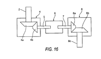
- FIG. 16 is a schematic view of the first bevel gear 4, the clutch 6 and the second bevel gear 8.
- the first bevel gear 4 comprises an input gear 4a and an output gear 4b.
- the input gear 4a is connected to the column shaft 2 (output shaft or the reaction motor 3), and the output gear 4b is connected to the first shaft 5.
- the axial direction of rotation inputted to the column shaft 2 is changed to the right angle direction (in the direction of the vehicle width) by the rotation direction conversion function of the first bevel gear 4, and the rotation is inputted to the clutch 6 via the first shaft 5.
- the first shaft 5 is formed so as to have a smaller diameter than the column shaft 2 and the third shaft 8c.
- the second bevel gear 8 comprises an input gear 8a and an output gear 8b.
- the input gear 8a is connected to the second shaft 7 and the output gear 8b is connected to the third shaft 8c.
- the axial direction of the rotation inputted to the second shaft 7 from the clutch 6 is converted to the right angle direction (in the longitudinal direction of the vehicle) by the rotation direction conversion function of the second bevel gear 8, and the rotation is inputted to the steering wheel-side cable reel 10a of the cable-type column 10 via the third shaft 8c.
- the second shaft 7 is similar to the first shaft 5, formed so as to have a smaller diameter than the column shaft 2 and the third shaft 8c.
- first bevel gear 4 and the second bevel gear 8 are the same as those of the bevel gear 4 shown in FIG. 3, description thereof is omitted.
- the first bevel gear 4 outputs the rotation of the column shaft 2 to the clutch 6, by increasing its speed
- the second bevel gear 8 outputs the rotation of the clutch 6 to the cable-type column 10 by decreasing its speed.
- the rotation speed of the column shaft 2 and the input rotation of the cable-type column 10 are identical.
- the clutch 6 In the event of failure of the steer-by-wire system, the clutch 6 is engaged, and the steering force of the steering wheel 1 is transmitted in order from the column shaft 2 ⁇ the first bevel gear 4 ⁇ the clutch 6 ⁇ the second bevel gear 8 ⁇ the cable-type column 10 ⁇ the steering mechanism 11.
- the road surface reaction from the steering controlled wheels 22 and 22 is transmitted in order from the steering mechanism 11 ⁇ the cable-type column 10 ⁇ the second bevel gear 8 ⁇ the clutch 6 ⁇ the first bevel gear 4 ⁇ the column shaft 2 ⁇ the steering wheel 1.
- the first bevel gear 4, which is a speed increasing gear, is provided on the steering wheel side of the clutch 6, and the second bevel gear 8, which is a speed decreasing gear, is provided on the side of the steering mechanism 11 from the clutch 6 and therefore the torques (steering force by the driver and road surface reaction) that are added to the clutch 6 become smaller than the input to the first bevel gear 4 and the output from the second bevel gear 8. Consequently, the torque capacity of the clutch 6 can be reduced to the minimum.
- the first bevel gear 4 is used so that the rotation shaft that is on the side of the front wheels 22 and 22 from the reaction motor 3 can be shifted from the axis of the column shaft 2 by the first bevel gear 4, the length of the steering unit A in the longitudinal direction of the vehicle can be reduced.
- the added torque to the first shaft 5, which connects the first bevel gear 4 and the clutch 6, and the second shaft 7, which connects the clutch 6 and the second bevel gear 8, are small, thereby achieving reduction in weight by the first shaft 5 and the second shaft 7 having a small diameter. Therefore, disengagement of the first shaft 5 and the second shaft 7 upon collision of the vehicle becomes easy. Consequently, upon collision of the vehicle, when an impact is added to the steering unit A, the first shaft 5 or the second shaft 7 is broken and the steering unit A moves towards the side of dash panel 9, thereby maintaining the distance between the steering wheel 1 and the driver, so that the impact to the driver is reduced.
- the first bevel gear 4 and the first shaft 5 are rotated with the steering wheel 1, and the second shaft 7, the second bevel gear 8 and the cable-type column 10 are rotated with the steering mechanism 11.
- the responsiveness, etc., of the reaction control directly affects the feeling of steering and therefore, it is desirable for the friction and inertia of the drag torque to be small.
- the clutch 6 has a small capacity and the first shaft 5 and the second shaft 7 are light in weight and therefore the influence of the drag torque can be reduced to the minimum thereby increasing the response of the reaction control and steering control.
- the first bevel gear 4 is provided between the reaction motor 3 and the clutch 6, it is possible to prevent the friction of the first bevel gear 4 from interfering with the steering reaction that is added to the steering wheel 1 by the reaction motor 3, and consequently, a discomfort of the steering can be prevented.
- the length of the steering unit in the axis direction can be set shorter than the length in the axis direction of the above-mentioned prior art. Consequently the vehicle mountability is improved and the freedom of the layout in the cabin space can be increased.
- the vehicle steering apparatus according to Embodiment 10 has advantages set forth below.
- the steering unit A having the steering wheel 1 and the steered unit B that steers the steering controlled wheels 22 and 22 can be mechanically separated.
- the apparatus comprises the backup unit (cable-type column 10) that mechanically transmits the rotation from the steering unit A to the steered unit B and the clutch 6 that carries out connection and disconnection of the backup unit, wherein a first bevel gear 4 is provided on the rotation shaft (first shaft 5) between the steering unit A and the clutch 6, and increases the output rotation to the clutch 6, and the second bevel gear 8 that is provided on the rotation shaft (second shaft 7) between the clutch 6 and the steered unit B, and that decreases the output rotation to the steered unit B. Therefore the torque added to the clutch 6 can be reduced relative to the input to the first bevel gear 4 and the output from the second bevel gear 8, and consequently the torque capacity of the clutch 6 can be limited to the minimum.
- the first bevel gear 4 has a rotation direction conversion function for changing the rotation axis direction of the steering wheel 1 so that the axis direction of the steering wheel 1 is different from the rotation axis direction of the clutch 6, and therefore the length in the axis direction of the steering unit A (length in the longitudinal direction of the vehicle (front and back direction)) can be set to be short. Consequently, the vehicle mountability is improved and the freedom of the layout in the cabin space can be increased. In addition, the friction of the rotation torque of the clutch during steering can be reduced to the minimum thereby improving the response of the reaction control.
- the second bevel gear 8 has a rotation direction conversion function for changing the input direction to the backup means with respect to the rotation axis direction of the steering wheel 1. That is, the rotation axis direction of the clutch 6 which has been changed by the first bevel gear 4 is changed by the second bevel gear 8 so that, the rotation direction inputted to the backup unit is returned to the direction approximately parallel to the column shaft 2.
- the diameter of the first shaft 5 between the first bevel gear 4 and the clutch 6 is smaller than the diameter of the column shaft 2 between the first bevel gear 4 and the steering wheel 1, the inertia due to the drag torque during steering can be reduced to the minimum thereby improving the response of the reaction control.
- disconnection upon collision is easy and therefore the impact on the driver upon collision can be reduced.
- the diameter of the second shaft 7 between the second bevel gear 8 and the clutch 6 is smaller than the diameter of the third shaft 8c between the second bevel gear 8 and the steered unit B, the inertia due to the drag torque during steering can be reduced to the minimum thereby improving the response of the steering control.
- disconnection upon collision is easy and therefore the impact on the driver upon collision can be reduced.
- the clutch 6 is a friction clutch, a misengagement during the engagement of the clutch can be prevented compared to the case of a dog clutch.
- Embodiment 11 is an example in which the increased rotation speed by the first bevel gear is reduced by the cable-type column.
- FIG. 17 is a schematic view of a vehicle steering apparatus according to Embodiment 11. Since the structure of Embodiment 11 is identical to Embodiment 10, the same numerals of Embodiment 10 are used for Embodiment 11, and the description thereof is omitted.
- the number of gears of the input gear 43a of the second bevel gear 43 is the same as that of the output gear 43b, and the gear ratio is one to one.
- the reel diameter of the steering wheel-side cable reel 44a of a the cable-type column 44 is set so as to be smaller than that of the pinion-side cable reel 44b, the increased rotation number inputted from the first bevel gear 4 by the steering comes back to the original rotation number (decreasing speed device).
- the diameter of the third shaft 43c that connects the second bevel gear 43 to the steering wheel-side cable reel 44a of the cable-type column 44 is smaller (the same diameter as the first shaft 5 and second shaft 7) than that of the column shaft 2.
- Embodiment 11 a control response can be improved. That is, since Embodiment 11 has a structure such that the rotation speed increased by the first bevel gear 4 is reduced by the cable-type column 44, the third shaft 43c as well as the first shaft 5 and the second shaft 7 becomes light in weight thereby allowing a reduction of the drag torque, so that the response of the steering control can be improved.
- the vehicle steering apparatus according to Embodiment 11 has advantages set forth below.
- the backup unit is the cable-type column 44 that transmits the input steering torque inputted by the steering wheel 1 to the steering controlled wheels 22 and 22 by the two cables upon the engagement of the clutch 6.
- the reel diameter of the steering wheel-side cable reel 44a of the cable-type column 44 is smaller than that of the pinion-side cable reel 44b. Therefore the third shaft 43c that connects the second bevel gear 43 to the steering-side cable reel 44a of the cable-type column 44 can be light in weight thereby reducing the inertia of the drag torque during the steering to a minimum.
- Embodiment 12 is an example in which the amount of increased rotation speed by a first bevel gear is reduced by a speed decreasing gear that is provided between a cable-type column and a steering mechanism.
- FIG. 18 is a schematic view of a vehicle steering apparatus according to Embodiment 12.
- the same numerals are assigned to the same structural elements as those of Embodiment 10 or 11. The description thereof is omitted.
- a speed decreasing gear (speed decreasing unit) 45 is provided between the pinion-side cable reel 10b of the cable-type column 10 and the steering mechanism 11.
- the gear ratio of the speed decreasing gear 45 (decreased speed ratio) is set so that the rotation number increased by the first bevel gear 4 may come back to the original rotation number.
- the cable friction can be reduced. That is, since the speed decreasing gear 45 that decreases the rotation speed that has been increased by the first bevel gear 4, is provided between the cable-type column 10 and steering mechanism 11, the torque that was added to the cable-type column 10 is reduced, so that the cable friction can be limited. Consequently, feeling of steering while the clutch is engaged is improved and the durability of the cable-type column 10 can be realized.
- the diameter of the steered-side cable reel 10a and the pinion-side cable reel 10b can be small so as to be light in weight, and therefore the inertia of the dragged torque can be limited to the minimum.
- the vehicle steering apparatus according to Embodiment 12 has advantages set forth below.
- the speed decreasing gear 45 connects the cable-type column 10 to the steering mechanism 11 of the steered unit B so that the torque added to the cable-type column 10 can be reduced, and the cable friction can be limited. Consequently, feeling of steering while the clutch is engaged can be improved and the durability of the cable-type column 10 can be realized.
- Embodiment 13 is an example in which a steering gear having a steering mechanism is used as a speed decreasing unit that decreases the rotation number that has been increased by the first bevel gear.
- FIG. 19 is a schematic view of a vehicle steering apparatus according to Embodiment 13.
- Embodiment 12 The same numerals as those of Embodiment 12 are assigned to the same structural elements as those of Embodiment 12, the description thereof is omitted.
- the steering gear ratio of the steering gear (speed decreasing unit) 46a of the steering mechanism 46 is set so that the rotation number of the steering unit, which has been increased by the first bevel gear 4 can come back to the original rotation number.
- the steering gear ratio Z0 satisfies the formula (4) set forth below.
- Z 0 Z 0 ⁇ ⁇ Z 2 / Z 1 where Z1>Z2
- Embodiment 13 uses the steering gear 46a of the steering mechanism 46 as the speed decreasing means, which reduces the rotation number that has been increased by the first bevel gear 4, and therefore, compared to the structure according to Embodiment 12 in which the speed decreasing gear 45 is separately provided, the number of parts can be reduced so that the length of a portion between the pinion-side cable pulley 10b of the cable-type column 10 and the steering mechanism 46 can be decreased.
- the vehicle steering apparatus of Embodiment 4 has advantages set forth below.
- the cost can be reduced by reducing the number of parts and the steered unit B can become compact, compared to the structure according to Embodiment 12, which has a separate speed decreasing unit.
- Embodiment 14 is an example in which the speed reduction ratio of the second bevel gear and the speed increasing ratio of the first bevel gear are different from each other. The structure thereof is described below.
- FIG. 20 is a schematic view of a first bevel gear 4, a clutch 6 and a second bevel gear 47 according to Embodiment 14.
- the same numerals as those of Embodiment 14 are assigned to the same structural elements as those of Embodiment 1.
- the speed decreasing ratio of the second bevel gear (speed decreasing unit) is different from the speed increasing ratio of the first bevel gear.
- the steering gear ratio Z0 satisfies the formula (5) set forth below.
- the steered amount of the steering controlled wheels 22 and 22 becomes larger than the steering amount of the steering wheel 1 so that the steering gear ratio can be configured to be quick.
- the steered amount of the steering controlled wheels 22 and 22 becomes smaller than the steering amount of the steering wheel 1 so that the steering gear ratio can be configured to be slow.
- the cable-type column 10 comprises a steering wheel-side cable pulley 10a (for example, FIG. 1) which is connected to a column shaft 2, a steering controlled wheel-side cable pulley 10b (for example, FIG. 1), which is provided on an edge of a pinion shaft 21(for example, FIG. 1), two inner cables 10g and 10h, which are connected to each other and which are winded around the cable pulleys 10a and 10b in opposite directions from each other, and outer tubes 10c and 10d that cover the inner cables 10g and 10h.
- a steering wheel-side cable pulley 10a for example, FIG. 1
- a steering controlled wheel-side cable pulley 10b for example, FIG. 1
- two inner cables 10g and 10h which are connected to each other and which are winded around the cable pulleys 10a and 10b in opposite directions from each other
- outer tubes 10c and 10d that cover the inner cables 10g and 10h.
- the steering wheel-side cable pulley 10a that is connected to the column shaft 2 is contained in the steering wheel-side pulley case 10e, and on the circumference of the pulley, the ends of the two inner cables 10g and 10h are fixed, and additionally there are cable gutters that guide one of the two inner cables 10g and 10h to be winded and the other cable to be re-winded.
- the steering controlled wheel-side cable pulley 10b that is connected to the end of the pinion shaft 21 is contained in the steering controlled wheel-side pulley case 10f, and on the circumference of the pulley, the ends of the two inner cables 10g and 10h are fixed to each other, and additionally cable gutters that guide one of the two inner cables 10g and 10h to be winded and the other cable to be re-winded are formed.
- the outer tubes 10c and 10d cover the inner tubes 10g and 10h, and connect the steering wheel-side pulley case 10e and the steering controlled wheel-side pulley case 10f.
- a nut to adjust the cable tension 10i is provided between the outer tubes 10c and 10d, and the steering controlled wheel-side pulley case 10f, respectively, and a spring 10j to adjust the cable tension is provided between the outer tubes 10c and 10d, and the steering wheel-side pulley case 10e, respectively.
- the nut to adjust the cable tension 10i and the spring to adjust the cable tension 10j are provided to adjust the cable tension (cable friction) by changing the length of the outer tubes 10c and 10d.
- the outer tubes 10c and 10d are, as shown in FIG. 22, structured such that two or more metal wires 101g and 101h are provided in the axis direction along the circumference of the liners 100g and 100h that are made of a synthetic resin pipe material with a small friction resistance, and metal bands 102g and 102h are winded around the circumference in a spiral, and in addition, their circumference is covered by materials 103g and 103h made of synthetic resin. Furthermore, inside the outer tubes 10c and 10d, inner cables 10g and 10h, which are made from metal twisted wire made of stainless steel or aluminum, etc., as shown in FIG. 23, are slidably contained.
- the outer tubes 10c and 10d support the tension that is applied in the axis direction by the two ore more metal wires 101 g and 101h, thereby preventing deformation thereof due to an extension.
- the metal wires 101g and 101h are prevented from being separated, by using the metal bands 102g and 102h when the inner cables 10g and 10h are bent.
- the bending of the outer tubes 10c and 10d is allowed by the spiral metal bands 102g and 102h.
- the cable-type column 10 has a structure in which the two cable pulleys 10a and 10b, which are connected to the column shaft 2 and the end of the pinion shaft 21, are connected by the outer tubes 10c and 10d and the two inner cables 10g and 10h, which are winded around the cable pulleys 10a and 10b, respectively in the opposite direction from each other.
- the steering wheel 1 When the steering wheel 1 is turned in one direction, one of the two sets of cables 10c and 10g, and cables 20d and 20h (sic) transmits the steering torque that is input by the driver, and the other cable transmits the reaction torque that is input by the steering controlled wheels 22 and 22, so as to perform the function equivalent to the column shaft 2.
- the second bevel gear 8 is provided in the cabin space, and the steering wheel-side pulley case 10e of the cable-type column 10 is provided outside the cabin space (inside the engine room).
- the second bevel gear 8 and the steering wheel-side pulley case 10e are fixed to the dash panel 9 while sandwiching the dash panel (partition) 9 that separates the engine room and the cabin space.
- the steered unit B comprises the steering mechanism 11 having a hydraulic assistance mechanism, the pinion shaft 21, and the steering controlled wheels 22 and 22.
- the steering mechanism 11 comprises a rack and pinion-type steering gear 11 a and steers the steering controlled wheels 22 and 22 by corresponding to the rotation of the pinion shaft 21.
- FIG. 24 is a perspective view of the dash panel 9 in order to explain about an installation method of the cable-type column according to Embodiments 10-14, which is viewed from the front of the vehicle.
- the second bevel gear 8 is aligned from the cabin space side at the designated assembling position on the dash panel 9.
- the steering wheel-side pulley case 10e is aligned from the outside of the cabin space on the dash panel 9.
- the steering wheel-side cable pulley 10a is fastened to the dash panel 9 using a bolt 54 from the outside of the cabin space so that the steering wheel-side pulley case 10e and the second bevel gear 8 are fixed to the vehicle body.
- an assembly performance of the cable-type column can be improved. That is, the second bevel gear 8 is provided in the cabin space, the steering wheel-side cable pulley case 10e is provided outside the cabin space and both of them are fixed to the dash panel 9, and therefore, the steering-side pulley case 10e can be provided without leading the cable of the cable-type column 10 through the dash panel 9, thereby allowing easy assembly of the cable-type column 10 to the vehicle body.
- Embodiments 10-14 since only one section of cable and one set of pulleys (steering wheel side and steering controlled wheel side) are required, compared to the technology disclosed in Japanese Laid Open Patent Application No. H10-67327 in which an intermediate interlocking means is provided between a steering wheel and a gear box, the structure thereof can be simplified and the number of parts is reduced so that the cost can be reduced.
- Embodiments 10-14 after the bevel gear 8 is fastened to the steering wheel-side pulley case 10e using a bolt, the steering wheel-side pulley case 10e is fastened to the dash panel 9 using a bolt thereby fastening the bevel gear 8 and steering wheel-side pulley case 10e to the vehicle body, so that the maintenance of the coaxial nature of the bevel gear 8 and the steering wheel-side pulley case 19a, and the sealing between the dash panel 9 and the steering wheel side pulley case 10e can be simultaneously carried out in a simple operation.
- the vehicle steering apparatus according to Embodiments 10-14 has advantages set forth below.
- the dash panel 9 separates the cabin space where the steering wheel 1 is provided, from the outside of the cabin space where the steered unit B is provided, the first bevel gear 4 that converts the axis direction of rotation inputted from the steering wheel 1 into another direction, and the second bevel gear 8 that converts axis direction of the rotation inputted from the first bevel gear 4 into the direction in which the gear 4 goes towards the dash panel 9, wherein the second bevel gear 8 is provided in the cabin space (the inside of the dash panel 9), and the steering wheel-side cable pulley 10a of the cable-type column 10 is provided outside the cabin space. Therefore, the assembly performance of the steering wheel-side cable pulley 10a can be improved without complicating the structure or increasing the number of parts.
- the bevel gear 8 is supported by the steering wheel-side pulley case 10e, and therefore the maintaining of the coaxiality of the bevel gear 8 and the steering wheel-side pulley 10a and the sealing between the dash panel 9 and the steering wheel-side pulley case 10e can be simultaneously carried out in a simple operation.
- waterproofing can be achieved with a conventional sealing structure (FIG. 8).
- Embodiment 15 is an example in which a cable-type column is used as a backup unit of the steer-by-wire system and a backup clutch is provided between the second bevel gear and the cable-type column.
- FIG. 26 shows the structure of the steering unit of the vehicle steering apparatus according to Embodiment 15.
- the same numerals as those of Embodiment 10 are assigned to the same structural elements as those of Embodiment 10.
- a clutch 6 is provided between the second bevel gear 8 and the steering wheel-side pulley case 10e of the cable-type column 10, and the clutch 6 is arranged in the cabin space and the steering side pulley case 10e is arranged outside the cabin space sandwiching the dash panel 9.
- the clutch 6 is fixed to the steering-side pulley case 10e from the outside of the cabin space by a bolt, in which the clutch 6 and the pulley case 10e sandwiches the dash panel 9, and the steering wheel-side pulley case 10e is fixed to the dash panel 9 from the outside of the cabin space by a bolt.
- the layout space in the engine room is enlarged. That is, the clutch 6 is provided between the second bevel gear 8 and the steering wheel-side pulley case 10e, and the clutch 6 is arranged in the cabin space. Since outside the cabin space over the dash panel 9, namely in the engine room, a variety of parts such as a brake unit, an ABC pedal unit, a wiper unit, and a variety of pipes are arranged, it is possible to reduce effect thereof in the layout of the engine room by providing the clutch 6 in the cabin space.
- the backup unit (clutch 6, cable-type column 10) can be integrated, thereby allowing a larger space around an instrument panel.
- the vehicle steering apparatus according to Embodiment 15 has advantages set forth below, in addition to the advantages (25) and (26) of Embodiments 10-14.
- the clutch 6 that can disconnect the cable-type column 10 and the steering wheel 1 is provided and is arranged between the second bevel gear 8 and the steering wheel-side cable pulley 10a, thereby allowing integration of the backup unit (clutch 6 and cable-type column 10).
- the structure between the first bevel gear 4 and the second bevel gear 8 can be simplified, and the space around the instrument panel can be increased.
- the clutch 6 Since the clutch 6 is provided in the cabin space, the clutch can be mounted in the vehicle even if there is no space for the clutch layout in the engine room.
- the clutch 6 is supported by the steering wheel-side pulley case 10e, and the steering wheel-side pulley case 10e is fixed to the dash panel 9, the coaxiality of the clutch 6 and the steering wheel-side pulley case 10e can be maintained while the space between the dash panel 8 and the steering wheel-side pulley case 10e can be sealed.
- Embodiment 16 differs from the structure of Embodiment 15 in that the backup clutch is provided outside the cabin space.
- FIG. 27 shows the structure of a steering unit of the vehicle steering apparatus according to Embodiment 16.
- the structure thereof that is identical to Embodiment 15 has the same numerals and the description is omitted.
- the same numerals as those of Embodiment 15 are assigned to the same structural elements as those of Embodiment 15.
- a clutch 6 is provided between the second bevel gear 8 and the steering wheel side pulley case 10e, and the second bevel gear 8 is provided in the cabin space and the clutch 6 is provided outside the cabin space sandwiching the dash panel 9.
- the second bevel gear 8 is fixed to the clutch 6 from the outside of the cabin space by a bolt, sandwiching the dash panel 9 therebetween and the clutch 6 is fixed to the dash panel 9 from the outside of the cabin space by a bolt.
- the layout space around an instrument panel is enlarged. That is, the clutch 6 is provided between the second bevel gear 8 and the steering wheel-side pulley case 10e, and the clutch 6 is provide outside the cabin space.
- the cabin space side of the dash panel 9 namely around the instrument panel area, a variety of parts such as an air conditioning unit, an ECU, a key cylinder, and a variety of harnesses are arranged and therefore, by providing the clutch 6 in the engine room, it is possible to allow less effect thereof in the layout of the cabin space.
- Embodiment 16 has advantages set forth below, in addition to the advantages (25) and (26) of Embodiments 10-14.
- the clutch 6 Since the clutch 6 is provided outside the cabin space, the clutch can be mounted in the vehicle even if there is no clutch layout space in the cabin space.
- the second bevel gear 8 Since the second bevel gear 8 is supported by the clutch 6, and fixed to the dash panel 9, the coaxiality of the second bevel gear 8 and the clutch 6 can be maintained while the space between the dash panel 9 and the steering wheel-side pulley case 10e can be sealed.
- Embodiment 17 is an example in which the second bevel gear that is provided in the cabin space and the cable-type column provided outside the cabin space are connected by a steering rotation shaft having a joint structure.
- FIG. 28 shows the structure of the steering unit of the vehicle steering apparatus according to Embodiment 17
- the same numerals as those of Embodiment 10 are assigned to the same structural elements as those of Embodiment 10.
- a universal joint 76 is provided between the second bevel gear 8 that is provided in the cabin space and the steering wheel-side pulley case 10e that is provided outside the cabin space, sandwiching the dash panel 9 therebetween.
- the universal joint 76 is provided in the cabin space so as to connect the shaft 77 that is connected to the second bevel gear 8 and the shaft 78 that is connected to the steering wheel-side cable pulley 10a. As shown in FIG. 29, on the tip of the two shafts 77 and 78, serrations 77a and 78a are formed, and these serrations 77a and 78a are inserted into the serration holes (not shown in the drawing) that are formed on the universal joint 76, and therefore the shafts 77 and 78 and the universal joint 76 are connected with the serration.
- the assembly is facilitated. That is, in case where the power transmission path between the units (second bevel gear 8 and steering wheel-side cable pulley 10a) that sandwich the dash panel 9 is formed by a steering rotation shaft, since the second bevel gear 8 and the steering wheel-side pulley case 10e need to be coaxially provided, the assembling is complicated.
- the coaxiality of the two shafts 77 and 78 can be maintained by simply inserting the shafts 77 and 78 into the universal joint 76.
- the universal joint 76 can absorb the offsetting of the shaft center of the shafts 77 and 78, thereby allowing easy connection of the torque transmission mechanism between the units (second bevel gear 8 and steering wheel-side cable pulley 10a) that sandwich the dash panel therebetween, and therefore the assembly operation can be easily carried out.
- Embodiment 17 has advantages set forth below, in addition to advantages (25) and (26) of Embodiments 10-14.
- the universal joint 76 is provided between the steering rotation shafts (shafts 77 and 78) that penetrates the dash panel 9 and therefore, the torque transmission mechanism between the units (second bevel gear 8 and steering wheel-side cable pulley 10a) that sandwich the dash panel 9 therebetween can be easily connected.
- the bevel gear is used as the rotation direction conversion means
- any suitable structure can be adopted and for example, a universal joint can be used therefor.
- the backup mechanism is not limited to the cable type column but may be a shaft, etc,
Abstract
Description
- The present invention relates to a steering apparatus for a vehicle. The invention also relates to a vehicle equipped with such an apparatus.
- In a conventional steer-by-wire system, a column shaft connected to a steering wheel is connected to a reaction motor, a clutch and a steering wheel side cable pulley of a backup means as described in, for example,
Japanese Laid Open Patent Application No. 2002-225733 - In the conventional vehicle steering apparatus having a cable-type column, one end of a first cable is connected to the steering wheel, and one end of a second cable is connected to a gear box. The other end of the first cable and the other end of the second cable are connected with an intermediate interlocking means provided between the steering wheel and the gear box. In such a system, it is not necessary to lead the cable through a dash panel that is provided between the steering wheel and the gear box so that it is possible to assemble the first and second cables without any interference. For example, see
Japanese Laid Open Published Patent Application No. H10-67327 - It is an aim of the invention to improve upon such conventional apparatus. Other aims and advantages of the invention will become apparent from the following description, claims and drawings.
- Aspects of the invention therefore provide an apparatus and a vehicle as claimed in the appended claims.
- According to another aspect of the invention there is provided a steering apparatus for a vehicle, comprising a steering unit having an operational input unit and a reaction generating unit, a steered unit that is mechanically separated from the steering unit and that steers steering controlled wheels, a clutch that is provided between the steering unit and steered unit, a backup unit that is provided between the clutch and the steered unit and transmits a steering torque that is inputted from the operational input unit, when the clutch is engaged, to the steering controlled wheels, and a first rotation conversion unit provided between the reaction generating unit and the clutch, for changing a rotation axis direction of the operational input unit.
- In an embodiment the first rotation conversion unit changes the rotation axis direction by about 90 degrees.
- In an embodiment the first rotation conversion unit outputs a rotation of the operational input unit towards the outside of the vehicle in a width direction of the vehicle.
- In an embodiment the first rotation conversion unit outputs a rotation of the operational input unit towards the inside of the vehicle in a width direction of the vehicle.
- In an embodiment the first rotation conversion unit outputs a rotation of the operational input unit in a downward direction of the vehicle.
- In an embodiment the backup unit comprises a cable-type column, and the clutch transmits the rotation outputted from the first rotation conversion unit to the cable-type column when the clutch is engaged.
- The apparatus may comprise a shaft that connects the first rotation conversion unit to the clutch wherein the shaft has a joint in which a connection thereof comes apart when a load is applied to the joint in a direction perpendicular to an axis direction of the shaft.
- The apparatus may comprise a second rotation conversion unit provided between the first rotation conversion unit and the steered unit that changes the rotation axis direction of the first rotation conversion unit towards the steered unit.
- In an embodiment the clutch is provided between the first rotation conversion unit and the second rotation conversion unit.
- In an embodiment the first rotation conversion unit further comprises a speed increasing unit that increases a rotation to be inputted to the clutch.
- In an embodiment the second rotation conversion unit includes a speed decreasing unit that decreases a rotation to be inputted to the clutch.
- In an embodiment the speed decreasing unit connects the backup unit and the steered unit.
- In an embodiment the speed decreasing unit is a steering gear of the steered unit.
- The apparatus may comprise a bulkhead that divides a cabin space and an outside of the cabin space, wherein the steering unit is provided in the cabin space, and the steered unit is provided outside of the cabin space, and the first and second rotation conversion units are provided on a steering unit side of the bulkhead and the backup unit is provided on a steered unit side of the bulkhead.
- In an embodiment the backup unit is a cable-type column, and a steering unit side pulley case of the cable-type column contains a steering unit side pulley and is fixed to the bulkhead.
- In an embodiment the second rotation conversion unit is fixed to the steering unit side pulley case.
- In an embodiment the clutch is provided between the second rotation conversion unit and the steering unit side pulley.
- In an embodiment the clutch is provided on the steering unit side of the bulkhead.
- In an embodiment the clutch is fixed to the steering unit side pulley case.
- In an embodiment the clutch is provided on the steered unit side of the bulkhead.
- The apparatus may comprise a bulkhead that divides a cabin space and an outside of the cabin space, wherein the steering unit is provided in the cabin space, and the steered unit is provided outside of the cabin space, and the first rotation conversion unit changes the rotation axis direction of the operational input unit towards a direction along the bulkhead.
- In an embodiment the steering unit provided in the cabin space, and the first rotation conversion units changes the rotation axis direction to reduce the length of the steering unit in the axis direction in the cabin space.
- In embodiments of the present invention, a rotation axis direction of a steering unit is changed to a different direction by a rotation direction conversion unit before the rotation transmitted from the steering unit is transmitted to a clutch, so that the length of the steering unit may be shortened. Thus, a steering apparatus for a vehicle may be reduced in size in the axis direction of the steering unit so that superior vehicle mountability may be obtained.
- Within the scope of this application it is envisaged that the various aspects, embodiments and alternatives set out in the preceding paragraphs, in the claims and in the following description may be taken individually or in any combination thereof.
- The present invention will now be described, by way of example only, with reference to the accompanying drawings in which:
- FIG. 1 shows a steer-by-wire system to which a vehicle steering apparatus according to
Embodiment 1 is applied; - FIG. 2 shows the detailed structure of a steering unit according to
Embodiment 1; - FIG. 3 is a cross-sectional view of a bevel gear according to
Embodiment 1; - FIG. 4 shows the steering unit according to a conventional steer-by-wire system;
- FIG. 5 is a schematic view of a steer-by-wire system in which the vehicle steering apparatus according to
Embodiment 2 is applied; - FIG. 6 is a schematic view of the steer-by-wire system in which a vehicle steering apparatus according to
Embodiment 3 is applied; - FIG.7 is a schematic view of a steer-by-wire system in which the vehicle steering apparatus according to
Embodiment 4 is employed; - FIGS. 8A, 8B and 8C show the structure of a first shaft according to
Embodiment 5 that connects a bevel gear and a clutch; - FIG. 9 shows the structure of a first shaft according to Embodiment 6;
- FIGS. 10A, 10B and 10C show the structure of a first shaft according to
Embodiment 7; - FIG. 11 is a schematic view of a steer-by-wire system to which the vehicle steering apparatus according to
Embodiment 8 is employed; - FIG. 12 is a schematic view of a steer-by-wire system to which the vehicle steering apparatus according to
Embodiment 9 is applied; - FIG. 13 is a schematic view of a steer-by-wire system in which the vehicle steering apparatus according to
Embodiment 10 is applied; - FIG. 14 shows a wet type multiple disk according to
Embodiment 10; - FIG. 15 shows the detailed structure of a steering unit according to
Embodiment 10; - FIG. 16 is a schematic view of the first bevel gear, the clutch and a second bevel gear;
- FIG. 17 is a schematic view of a vehicle steering apparatus according to
Embodiment 11; - FIG. 18 is a schematic view of a vehicle steering apparatus according to Embodiment 12;
- FIG. 19 is a schematic view of a vehicle steering apparatus according to
Embodiment 13 ; - FIG. 20 is a schematic view of the detailed structure of a first bevel gear, a clutch and a second bevel gear;
- FIGS. 21A, 2 1 B and 21C show a cable-type column;
- FIG. 22 is a partially cross-sectional and perspective view of the structure of an outer tube and an inner tube;
- FIG. 23 is a cross-sectional view of the structure of an outer tube and an inner tube;
- FIG. 24 is a perspective view of a dash panel which is viewed from the front side of the vehicle, illustrating a method of mounting a cable type column;
- FIG. 25 is a plan view of a gasket;
- FIG. 26 is a schematic view of a steering unit of a vehicle steering apparatus according to
Embodiment 15; - FIG. 27 is a schematic view of a steering unit of a vehicle steering apparatus according to
Embodiment 16; - FIG. 28 is a schematic view of a steering unit of a vehicle steering apparatus according to
Embodiment 17; and - FIG. 29 is a diagram showing a method for connecting a shaft and a universal joint.
- FIG. 1 is a schematic view of an overview structure of a steer-by-wire system to which a vehicle steering apparatus according to
Embodiment 1 is applied. The vehicle steering apparatus comprises a steering unit A, a cable-type column 10, a steered unit B, and acontroller 19, each of which will be described below. - As shown in FIGS. 1 and 2, the steering unit A comprises a steering wheel
operation input unit 1, acolumn shaft 2, a reaction motor (reaction actuator) 3, a bevel gear (a rotation direction conversion unit) 4, aclutch 6, a steeringwheel angle sensor 13, and aresolver 15. - The
reaction motor 3 is a coaxial motor, whose output axis is coaxial with thecolumn shaft 2, and outputs a steering reaction torque to thecolumn shaft 2, which simulates a road surface reaction according to a command current value from thecontroller 19. Thebevel gear 4 is provided between thereaction motor 3 and theclutch 6, and changes the rotation axis direction of the steering wheel 1 (axis direction of the column shaft 2) so as to be different from the rotation axis direction of theclutch 6. - The
clutch 6 is provided between thecolumn shaft 2 and the cable-type column 10. InEmbodiment 1, an electromagnetic clutch is used. When the clutch 6 is engaged, the steering torque applied to thesteering wheel 1 is mechanically transmitted to thesteering mechanism 11. In addition, the steeringwheel angle sensor 13 detects the rotation angle of thecolumn shaft 2. Theresolver 15 detects the rotation angle of thereaction motor 3. - The cable-
type column 10 is a mechanical backup mechanism that carries out a column shaft function for transmitting a torque in a backup mode in which theclutch 6 is engaged, and is diverted so as not to interference with members that exist between the steering unit A and the steered unit B. The cable-type column 10 is structured such that two inner cables are wound around the steering wheelside cable reel 10a that is connected to thecolumn shaft 2, and a pinionside cable reel 10b that is connected to apinion shaft 21, in opposite directions to each other. The ends of these two inner cables are fixed tocable reels outer tubes - The steered unit B comprises a
steering mechanism 11, aresolver 16, atorque sensor 17, anencoder 18, steeredside motors pinion shaft 21 and steering controlledwheels - The
steering mechanism 11 has a rack and pinion-type steering gear and steers the steering controlledwheels pinion shaft 21. The steeredside motors pinion shaft 21 via an attenuator such as a worm and worm wheels, etc, and outputs the steered torque for steering the steering controlledwheels pinion shaft 21 in correspondence with the command current value from thecontroller 19. - The
resolver 16 detects the motor rotation angle of the steeredside motors torque sensor 17 detects the input torque to thepinion shaft 21. Theencoder 18 detects the rotation angle of thepinion shaft 21. - Information detected by the steering
wheel angle sensor 13, a torque sensor 14, theresolvers torque sensor 17 and theencoder 18 is inputted to thecontroller 19, so as to drive and control thereaction motor 3 and the steeredside motors - During the normal steer-by-wire control (in which the
clutch 6 is released), the steeringwheel angle sensor 13 detects the rotation angle of thesteering wheel 1, and based on the detected rotation angle, thecontroller 19 calculates the steering amount of thesteering gear 11, and thecontroller 19 outputs the command current value for driving the steeredunit side motors steering mechanism 11 is driven. At this time, thetorque sensor 17 detects the reaction force that is applied to thesteering mechanism 11 and the command current value for driving thereaction motor 3 is outputted from thecontroller 19, so that the steering reaction force is applied to thesteering wheel 1. - In the event of failure of the steer-by-wire system, the
clutch 6 is engaged so as to mechanically connect thesteering wheel 1 to thesteering mechanism 11. At this time, the operation force of thesteering wheel 1 is transmitted from thesteering wheel 1, to thecolumn shaft 2, thebevel gear 4, theclutch 6, the cable-type column 10 and thesteering mechanism 11. - Description of the structure of the steering unit will be given below. FIG. 2 shows the steering unit A according to
Embodiment 1. The steering unit A is provided inside a cabin space (a vehicle interior for a driver to drive the vehicle) which is sectioned from the front body (e.g., engine room) by a dash panel (bulkhead) 9. Thebevel gear 4 and the clutch 6 are connected by afirst shaft 5, and theclutch 6 and the steering wheelside cable reel 10a are connected by asecond shaft 7. Because of thebevel gear 4, the direction of the rotation axis m of thesteering wheel 1, thecolumn shaft 2 and thereaction motor 3 is perpendicular to the rotation axis n of thefirst shaft 5,clutch 6 and thesecond shaft 7. In other words, thebevel gear 4 changes the rotation axis direction of thesteering wheel 1 towards a direction along thedash panel 9. However, the angle formed by the direction of the rotation axis m and the direction of the rotation axis n is not limited to 90 degrees but may be greater to or less than 90 degrees. - FIG. 3 is a cross-sectional view of the
first bevel gear 4. Thefirst bevel gear 4 comprises aninput shaft 4c and anoutput shaft 4d. One end of theinput shaft 4c is connected to thecolumn shaft 2, and the other end thereof is connected to theinput gear 4a. One end of theoutput shaft 4d is connected to theoutput gear 4b and the other end thereof is connected to thefirst shaft 5. - The input and
output gears casing 4e. Theinput shaft 4c is supported by thecasing 4e via twoneedle bearings output shaft 4d is supported by thecasing 4e via twoneedle bearings ball bearing 4j. - According to
Embodiment 1, the size in the axis direction of the apparatus is reduced by converting the rotation axis direction. Description thereof will be given below. - FIG. 4 shows a steering unit of a conventional steer-by-wire system. In such a conventional steering system, since a reaction motor, a clutch and a steering wheel side cable reel of the cable-type column are provided in series, in other words, coaxially on the axis of the column shaft that is connected to the steering wheel, the length in the axis direction L0 becomes necessarily long. In order to avoid the interference with the dash panel (dashboard) and also in order to avoid the impact to the driver via the column shaft during a vehicle collision, it is desirable that the length of the steering unit in the axis direction be as short as possible.
- In contrast, since in
Embodiment 1, thebevel gear 4 that changes the direction of the rotation axis n of the clutch 6 is provided, so that the direction of rotational axis n of the clutch 6 is perpendicular to the direction of the rotation axis m of thesteering wheel 1, the length L1 (FIG. 2) in the axis direction can be set shorter than the length L0 in the axis direction of the above-mentioned prior art. Consequently, the vehicle mountability can be improved and the freedom of the cabin space layout can be increased. - In addition, in
Embodiment 1, since thebevel gear 4 is provided between thereaction motor 3 and theclutch 6, friction, etc., from thebevel gear 4 does not intervene with the steering reaction that is applied to thesteering wheel 1 by thereaction motor 3 thereby avoiding any influence, so that discomfort of steering can be prevented. - The vehicle steering apparatus according to
Embodiment 1 has advantages set forth below. - In the vehicle steering apparatus, the steering unit A having the
steering wheel 1 and thereaction motor 3, and the steered unit B that steers the steering controlledwheels steering wheel 1 to the steering controlledwheels clutch 6 is engaged. Thebevel gear 4 that changes from the rotation axis direction of thesteering wheel 1 to the rotation axis direction of the clutch 6 is provided between thereaction motor 3 and theclutch 6. Therefore, arrangement of the clutch 6 on the rotation axis of thesteering wheel 1 is not needed thereby reducing the length L1 in the axis direction of the steering unit A, so that the vehicle mountability can be improved compared to the prior art. In addition, thebevel gear 4 is provided on the side of the steering controlledwheels reaction motor 3 thereby preventing the discomfort of steering due to the friction, etc., by thebevel gear 4. - The
bevel gear 4 generates an output in the rotation axis direction of the clutch 6 at an approximate right angle relative to the rotation axis direction of thesteering wheel 1, and therefore the freedom of layout can be increased thereby reducing the length of the steering unit A in the axis direction to the minimum. - Since the backup unit comprises the cable-
type column 10, and the clutch 6 transmits the rotation generated by thesteering wheel 1 to the cable-type column 10 when theclutch 6 is engaged, thecolumn shaft 2 can be prevented from moving into the cabin space upon a vehicle collision. - The
reaction motor 3 comprises a coaxial motor whose output shaft is coaxially provided with thecolumn shaft 2 and therefore, the length of thecolumn shaft 2 in the diameter direction can be reduced and also a high output motor can be used. In addition, even in the case where a large coaxial motor in the axis direction is employed, the length L1 in the axis direction can be shorter than in case where the output shaft of a motor is connected to thecolumn shaft 2 via a worm & worm wheel, thereby increasing the freedom of layout. - FIG. 5 is a schematic view of a steer-by-wire system in which a steering apparatus for vehicle according to
Embodiment 2 is applied. Abevel gear 4 according toEmbodiment 2 is provided so that rotation of thesteering wheel 1 is outputted in a width direction of the vehicle towards the outside of the vehicle. Acommunication hole 9a that allows theouter tubes type column 10 come out of the cabin space is formed on the outside portion of thedash panel 9 in the vehicle width direction. - According to
Embodiment 2, interference with members provided in the engine room can be avoided. - That is, since the rotation of the
steering wheel 1 is outputted to the outside of the vehicle width direction by thebevel gear 4, theouter tubes type column 10 can be rerouted, on a side portion of the vehicle so as not to easily intervene with the engine room members. - The vehicle steering apparatus according to
Embodiment 2 has advantages set forth below, in addition to the advantages (1) to (4) ofEmbodiment 1 described above. - Since the
bevel gear 4 outputs the rotation of thesteering wheel 1 towards the outside of the vehicle in a width direction of the vehicle, theouter tubes type column 10 can be led on the side portion of the vehicle when they are led from the inside to the outside of the cabin space, thereby easily avoiding any intervention with the engine room members. - FIG. 6 is a schematic view of a steer-by-wire system in which a steering apparatus for a vehicle according to
Embodiment 3 is applied. Thebevel gear 4 according toEmbodiment 3 is provided so that the rotation of thesteering wheel 1 is outputted towards the inside of the vehicle in a width direction of the vehicle. Acommunication hole 9b that allows theouter tubes dash panel 9 in the width direction of the vehicle. - According to
Embodiment 3, details of the dash panel are set forth below. - In
Embodiment 2, thecommunication hole 9a is formed on the outside portion of thedash panel 9 in the width direction of the vehicle, and therefore a two types of dash panels have to be prepared for a right-hand steering wheel vehicle and a left-hand steering wheel vehicle. Nonetheless, according toEmbodiment 3, thecommunication hole 9b is formed at the approximate center location of thedash panel 9 in the width direction of the vehicle so that thedash panel 9 can be shared by both a right-hand steering wheel vehicle and a left-hand steering wheel vehicle thereby allowing a cost reduction. - The vehicle steering apparatus according to
Embodiment 3 has advantages set forth below, in addition to the advantages (1) to (4) ofEmbodiment 1 described above. - Since the
bevel gear 4 outputs the rotation of thesteering wheel 1 towards the inside of the vehicle in the width direction of the vehicle, thecommunication hole 9b provided at the approximate center of thedash panel 9 can be shared by both the left-hand and right-hand steering wheel vehicle. - FIG. 7 is a schematic view of a steer-by-wire system in which a steering apparatus for a vehicle according to
Embodiment 4 is employed. Thebevel gear 4 is arranged so as to output the rotation of thesteering wheel 1 in a downward direction of the vehicle. - According to
Embodiment 4, interference with the members provided in the engine room can be avoided. That is, thebevel gear 4 outputs the rotation of thesteering wheel 1 in the downward direction of the vehicle so that theouter tubes type column 10 can be rerouted on the bottom portion of the vehicle so as not to interfere with the engine room members. - The vehicle steering apparatus according to
Embodiment 4 has advantages set forth below, in addition to the advantages (1) to (4) according toEmbodiment 1. - Since the
bevel gear 4 outputs the rotation of thesteering wheel 1 in the downward direction of the vehicle, theouter tubes type column 10 can be led on the bottom of the vehicle when they are led from the inside to the outside of the cabin space, thereby easily avoiding interference with the engine room members. - FIGS. 8A, 8B and 8C show the structure of a
first shaft 5 according toEmbodiment 5 in which thefirst shaft 5 connects thebevel gear 4 andclutch 6. Thefirst shaft 5 comprises twomembers members members concave portions 23a are formed on themember 23 and correspondingconvex portions 24a that engage with theconcave portions 23a are formed on themember 24. At the joint 25, theconcave portions 23a and theconvex portions 24a that form a mating structure are disengaged when a load F in the direction perpendicular to the axis direction is applied. - Next, description of impact absorption upon a collision will be given below.
- During a vehicle collision (in particular, a frontal collision), when an impact is added from the
steering wheel 1 to thecolumn shaft 2 → thereaction motor 3 → thebevel gear 4, thecolumn shaft 2 attempts to disengage from the steering unit A. However, inEmbodiment 5, thefirst shaft 5 that connects thebevel gear 4 to the clutch 6 breaks and therefore thecolumn shaft 2 comes off the members. In other words, when an impact is added to the steering unit A, thefirst shaft 5 breaks and the steering unit A moves to a side of thedash panel 9 to maintain a distance between thesteering wheel 1 and the driver and therefore, the impact to the driver is reduced. In addition, during a vehicle collision, if thedash panel 9 moves backwards first and then an impact is added, the same action will take place. - The vehicle steering apparatus according to
Embodiment 5 has advantages set forth below, in addition to the advantages (1) to (4) ofEmbodiment 1. - The
first shaft 5 connects thebevel gear 4 to theclutch 6, and thefirst shaft 5 has the joint 25 at which the twomembers first shaft 5 receives a load from a direction intersecting with the axis direction, and a load F in the direction perpendicular to the axis direction is applied, and therefore the impact on the driver can be reduced during a vehicle collision. - The joint 25 has the mating structure in which the two
members wheels - Since at the joint 25, the
member 23 has theconcave shape 23a and themember 24 has correspondingconvex shape 24a that engages with theconcave shape 23a, the joint that breaks upon collision can be constructed with a simple structure. - FIG. 9 shows the structure of a
first shaft 5 according toEmbodiment 6. Thefirst shaft 5 comprises a joint 26 in whichsmall diameter portions 26a andlarge diameter portions 26b are provided in alternation, and this joint 26 is designed so that thesmall diameter portions 26a will break when a load F is applied in the direction perpendicular to the axis direction. - Since an operation of
Embodiment 6 is the same as that ofEmbodiment 5, the description is omitted. - The vehicle steering apparatus according to
Embodiment 6 has advantages set forth below, in addition to the advantages (1) to (4) ofEmbodiment 1. - The joint 26 has a shape by which it folds when a load F in the direction perpendicular to the axis is applied, and therefore the impact on the driver can be reduced during a vehicle collision.
- FIGS. 10A, 10B and 10C show the structure of a
first shaft 5 according toEmbodiment 7. Thefirst shaft 5 comprises twomembers members member 27 has anopen shape 27a, which is a cross shaped recess, and a cross shapedprojection 28a that generally corresponds to theopen shape 27a is formed on the side of themember 28. This joint 29 has a mating structure in which theopen shape 27a and thecross-shaped projection 28a are disengaged when a load F in the perpendicular direction is applied. - The operation of
Embodiment 7 is the same as that ofEmbodiment 5 and therefore the description thereof is omitted. - The vehicle steering apparatus according to
Embodiment 7 has advantages set forth below, in addition to the advantages (1) to (4) ofEmbodiment 1, and the advantage (8) ofEmbodiment 5. - Since at the joint 29, the
member 27 has theopen shape 27a and themember 28 has the projectedshape 28a that engages with theopen shape 27a, the joint that breaks upon collision can be constructed with a simple structure. - FIG. 11 is a schematic view of a steer-by-wire system to which a steering apparatus for a vehicle according to
Embodiment 8 is employed. In addition to the structure ofEmbodiment 5,Embodiment 8 comprises aprojection 30 that promotes a break by coming into contact with thejoint portion 25 when the steering unit A moves towards the front of the vehicle body, and which is provided on thedash panel 9 facing the joint 25. - According to
Embodiment 8, dismantling of the steering unit upon a collision is promoted. - That is, upon a vehicle collision, the steering unit A moves towards the
dash panel 9 and comes in contact with theprojection 30 that is provided on thedash panel 9 and therefore thefirst shaft 5 is securely broken by the contact with theprojection 30 so that the steering unit A can be dismantled. - The vehicle steering apparatus according to
Embodiment 8 has advantages set forth below, in addition to the advantages (1) to (4) ofEmbodiment 1, and the advantage (8) ofEmbodiment 5. - Since the
projection 30 that applies a load to the joint 25 in the perpendicular direction is provided, a break of thefirst shaft 5 is promoted upon a collision so that the impact on the driver can be reduced. - Since the
projection 30 is provided on thedash panel 9 of the vehicle so as to face the joint 25, when the steering unit A comes close to thedash panel 9 upon a vehicle collision, it securely comes in contact with thefirst shaft 5 to break thefirst shaft 5, so that the steering unit A can be dismantled. - FIG. 12 is a schematic view of a steer-by-wire system to which a steering apparatus for a vehicle according to
Embodiment 9 is applied.Embodiment 8 is different fromEmbodiment 9 in that aprojection 31 is provided so as to face the joint 25 provided on the steering unit A (a casing of the reaction motor 3). An operation ofEmbodiment 9 is the same as that ofEmbodiment 8 and a description thereof is omitted. - The vehicle steering apparatus according to
Embodiment 9 has advantages set forth below, in addition to the advantages (1) to (4) ofEmbodiment 1, the advantage (8) ofEmbodiment 5, and the advantage (13) ofEmbodiment 8. - Since the
projection 31 is provided so as to face the joint 25 provided on the steering unit A, it securely comes in contact with thefirst shaft 5 during a collision, thereby breaking thefirst shaft 5, and the steering unit A can be dismantled. - FIG. 13 is a schematic view of a steer-by-wire system in which a steering apparatus for a vehicle according to
Embodiment 10 is applied. The same numerals are assigned to the same structural elements as these ofEmbodiment 1. The vehicle steering apparatus according toEmbodiment 10 comprises a steering unit A, a cable-type column (backup unit) 10, a steered unit B, and acontroller 19. Each of the structures will be described below. - The steering unit A comprises a steering wheel (operation input unit) 1, a
column shaft 2, areaction motor 3, a first bevel gear (speed increasing unit) 4, aclutch 6, a steered side second bevel gear (speed decreasing unit) 8, a steeringwheel angle sensor 13, and aresolver 15. - The
reaction motor 3 is a coaxial motor, whose output axis is coaxial with thecolumn shaft 2, and outputs a steering reaction torque that simulates a road surface reaction to thecolumn shaft 2 according to a command current value from thecontroller 19. Thefirst bevel gear 4 is provided between thereaction motor 3 and theclutch 6 and changes the rotation axis direction of thesteering wheel 1 so that the rotational axis direction of thesteering wheel 1 is different from the rotation shaft direction of the clutch 6 (axis direction of the column shaft 2). - The
clutch 6 is provided between thecolumn shaft 2 and the cable-type column 10. InEmbodiment 10, a wet-type multiple disk clutch as shown in FIG. 14 is used. In FIG. 14, theclutch 6 comprises themain body 6a, aninner disk 6b, anouter disk 6c, apressure plate 6d, alever 6e, alever pin 6f, arelease spring 6g, anadjustment plate 6h, alocking pin 6i, anut 6j, a parallel key 6k, ashifter pulley 6m, alocking plate 6n, and alocking pin spring 6p. - In the event of failure of the steer-by-wire system, the
clutch 6 is engaged so as to mechanically connect thesteering wheel 1 to thesteering mechanism 11. At this time, the operation force of thesteering wheel 1 is transmitted from thesteering wheel 1, to thecolumn shaft 2, thefirst bevel gear 4, theclutch 6, thesecond bevel gear 8, the cable-type column 10 and thesteering mechanism 11. - Next, the structure of the steering unit will be described below.
- As shown in FIG. 15, the steering unit A is provided inside the cabin space which is sectioned from the engine room of the vehicle body by a
dash panel 9. Thefirst bevel gear 4 and the clutch 6 are connected by a first shaft (rotation shaft) 5, and theclutch 6 and thesecond bevel gear 8 are connected by a second shaft (rotation shaft) 7. Thesecond bevel gear 8 and the steering wheel-side cable reel 10a are connected by a third shaft (rotation shaft) 8c. - FIG. 16 is a schematic view of the
first bevel gear 4, theclutch 6 and thesecond bevel gear 8. - The
first bevel gear 4 comprises aninput gear 4a and anoutput gear 4b. Theinput gear 4a is connected to the column shaft 2 (output shaft or the reaction motor 3), and theoutput gear 4b is connected to thefirst shaft 5. The axial direction of rotation inputted to thecolumn shaft 2 is changed to the right angle direction (in the direction of the vehicle width) by the rotation direction conversion function of thefirst bevel gear 4, and the rotation is inputted to theclutch 6 via thefirst shaft 5. Thefirst shaft 5 is formed so as to have a smaller diameter than thecolumn shaft 2 and thethird shaft 8c. - The
second bevel gear 8 comprises aninput gear 8a and anoutput gear 8b. Theinput gear 8a is connected to thesecond shaft 7 and theoutput gear 8b is connected to thethird shaft 8c. The axial direction of the rotation inputted to thesecond shaft 7 from theclutch 6 is converted to the right angle direction (in the longitudinal direction of the vehicle) by the rotation direction conversion function of thesecond bevel gear 8, and the rotation is inputted to the steering wheel-side cable reel 10a of the cable-type column 10 via thethird shaft 8c. Thesecond shaft 7 is similar to thefirst shaft 5, formed so as to have a smaller diameter than thecolumn shaft 2 and thethird shaft 8c. - In addition, since the structures of the
first bevel gear 4 and thesecond bevel gear 8 are the same as those of thebevel gear 4 shown in FIG. 3, description thereof is omitted. - Where the number of gears of the input gears 4a and
output gears 4b of thefirst bevel 4 is Z1 and Z2, respectively, and the number of gears of the input gears 8a andoutput gears 8b of thesecond bevel gear 8 is Z1' and Z2', respectively, the correlation between the number of gears satisfies a formula (1) set forth below.
where Z1>Z2, Z1'<Z2' - In other words, the
first bevel gear 4 outputs the rotation of thecolumn shaft 2 to theclutch 6, by increasing its speed, and thesecond bevel gear 8 outputs the rotation of the clutch 6 to the cable-type column 10 by decreasing its speed. In addition, the rotation speed of thecolumn shaft 2 and the input rotation of the cable-type column 10 are identical. - Description of torque capacity reduction of the clutch will be given below.
- In the event of failure of the steer-by-wire system, the
clutch 6 is engaged, and the steering force of thesteering wheel 1 is transmitted in order from thecolumn shaft 2 → thefirst bevel gear 4 → the clutch 6 → thesecond bevel gear 8 → the cable-type column 10 → thesteering mechanism 11. The road surface reaction from the steering controlledwheels steering mechanism 11 → the cable-type column 10 → thesecond bevel gear 8 → the clutch 6 → thefirst bevel gear 4 → thecolumn shaft 2 → thesteering wheel 1. - According to
Embodiment 10, thefirst bevel gear 4, which is a speed increasing gear, is provided on the steering wheel side of the clutch 6, and thesecond bevel gear 8, which is a speed decreasing gear, is provided on the side of thesteering mechanism 11 from theclutch 6 and therefore the torques (steering force by the driver and road surface reaction) that are added to the clutch 6 become smaller than the input to thefirst bevel gear 4 and the output from thesecond bevel gear 8. Consequently, the torque capacity of the clutch 6 can be reduced to the minimum. - In addition, according to
Embodiment 10, since thefirst bevel gear 4 is used so that the rotation shaft that is on the side of thefront wheels reaction motor 3 can be shifted from the axis of thecolumn shaft 2 by thefirst bevel gear 4, the length of the steering unit A in the longitudinal direction of the vehicle can be reduced. - Description of simplification of dismantling upon collision will be described below.
- According to
Embodiment 10, the added torque to thefirst shaft 5, which connects thefirst bevel gear 4 and theclutch 6, and thesecond shaft 7, which connects theclutch 6 and thesecond bevel gear 8, are small, thereby achieving reduction in weight by thefirst shaft 5 and thesecond shaft 7 having a small diameter. Therefore, disengagement of thefirst shaft 5 and thesecond shaft 7 upon collision of the vehicle becomes easy. Consequently, upon collision of the vehicle, when an impact is added to the steering unit A, thefirst shaft 5 or thesecond shaft 7 is broken and the steering unit A moves towards the side ofdash panel 9, thereby maintaining the distance between thesteering wheel 1 and the driver, so that the impact to the driver is reduced. - During a normal steer-by-wire control operation, the
first bevel gear 4 and thefirst shaft 5 are rotated with thesteering wheel 1, and thesecond shaft 7, thesecond bevel gear 8 and the cable-type column 10 are rotated with thesteering mechanism 11. In particular, the responsiveness, etc., of the reaction control directly affects the feeling of steering and therefore, it is desirable for the friction and inertia of the drag torque to be small. - According to
Embodiment 10, theclutch 6 has a small capacity and thefirst shaft 5 and thesecond shaft 7 are light in weight and therefore the influence of the drag torque can be reduced to the minimum thereby increasing the response of the reaction control and steering control. In addition, since thefirst bevel gear 4 is provided between thereaction motor 3 and theclutch 6, it is possible to prevent the friction of thefirst bevel gear 4 from interfering with the steering reaction that is added to thesteering wheel 1 by thereaction motor 3, and consequently, a discomfort of the steering can be prevented. - According to
Embodiment 10, since thefirst bevel gear 4 that converts the axis direction of the rotation shaft of thesteering wheel 1 so that the axis direction of the rotation shaft of the clutch 6 is the width direction of the vehicle, is provided, the length of the steering unit in the axis direction can be set shorter than the length in the axis direction of the above-mentioned prior art. Consequently the vehicle mountability is improved and the freedom of the layout in the cabin space can be increased. - The vehicle steering apparatus according to
Embodiment 10 has advantages set forth below. - In the vehicle steering apparatus, the steering unit A having the
steering wheel 1 and the steered unit B that steers the steering controlledwheels first bevel gear 4 is provided on the rotation shaft (first shaft 5) between the steering unit A and theclutch 6, and increases the output rotation to theclutch 6, and thesecond bevel gear 8 that is provided on the rotation shaft (second shaft 7) between the clutch 6 and the steered unit B, and that decreases the output rotation to the steered unit B. Therefore the torque added to the clutch 6 can be reduced relative to the input to thefirst bevel gear 4 and the output from thesecond bevel gear 8, and consequently the torque capacity of the clutch 6 can be limited to the minimum. - The
first bevel gear 4 has a rotation direction conversion function for changing the rotation axis direction of thesteering wheel 1 so that the axis direction of thesteering wheel 1 is different from the rotation axis direction of the clutch 6, and therefore the length in the axis direction of the steering unit A (length in the longitudinal direction of the vehicle (front and back direction)) can be set to be short. Consequently, the vehicle mountability is improved and the freedom of the layout in the cabin space can be increased. In addition, the friction of the rotation torque of the clutch during steering can be reduced to the minimum thereby improving the response of the reaction control. - The
second bevel gear 8 has a rotation direction conversion function for changing the input direction to the backup means with respect to the rotation axis direction of thesteering wheel 1. That is, the rotation axis direction of the clutch 6 which has been changed by thefirst bevel gear 4 is changed by thesecond bevel gear 8 so that, the rotation direction inputted to the backup unit is returned to the direction approximately parallel to thecolumn shaft 2. - Since the diameter of the
first shaft 5 between thefirst bevel gear 4 and theclutch 6 is smaller than the diameter of thecolumn shaft 2 between thefirst bevel gear 4 and thesteering wheel 1, the inertia due to the drag torque during steering can be reduced to the minimum thereby improving the response of the reaction control. In addition, disconnection upon collision is easy and therefore the impact on the driver upon collision can be reduced. - Since the diameter of the
second shaft 7 between thesecond bevel gear 8 and theclutch 6 is smaller than the diameter of thethird shaft 8c between thesecond bevel gear 8 and the steered unit B, the inertia due to the drag torque during steering can be reduced to the minimum thereby improving the response of the steering control. In addition, disconnection upon collision is easy and therefore the impact on the driver upon collision can be reduced. - Since the
clutch 6 is a friction clutch, a misengagement during the engagement of the clutch can be prevented compared to the case of a dog clutch. -
Embodiment 11 is an example in which the increased rotation speed by the first bevel gear is reduced by the cable-type column. - FIG. 17 is a schematic view of a vehicle steering apparatus according to
Embodiment 11. Since the structure ofEmbodiment 11 is identical toEmbodiment 10, the same numerals ofEmbodiment 10 are used forEmbodiment 11, and the description thereof is omitted. - According to
Embodiment 11, the number of gears of theinput gear 43a of thesecond bevel gear 43 is the same as that of theoutput gear 43b, and the gear ratio is one to one. - Since the reel diameter of the steering wheel-side cable reel 44a of a the cable-
type column 44 is set so as to be smaller than that of the pinion-side cable reel 44b, the increased rotation number inputted from thefirst bevel gear 4 by the steering comes back to the original rotation number (decreasing speed device). - When the number of gears of the input gears 4a of the first bevel gear and that of the output gears 4b are Z1 and Z2, respectively, and the reel diameter of the steering wheel side cable reel 44a and that of the pinion side cable reel 24b are d1 and d2, respectively, the correlation between the numbers of gears and the reel diameters satisfies the formula (2) set forth below.

where Z1>Z2, d2>d1 - In
Embodiment 11, the diameter of thethird shaft 43c that connects thesecond bevel gear 43 to the steering wheel-side cable reel 44a of the cable-type column 44 is smaller (the same diameter as thefirst shaft 5 and second shaft 7) than that of thecolumn shaft 2. - According to
Embodiment 11, a control response can be improved. That is, sinceEmbodiment 11 has a structure such that the rotation speed increased by thefirst bevel gear 4 is reduced by the cable-type column 44, thethird shaft 43c as well as thefirst shaft 5 and thesecond shaft 7 becomes light in weight thereby allowing a reduction of the drag torque, so that the response of the steering control can be improved. - The vehicle steering apparatus according to
Embodiment 11 has advantages set forth below. - The backup unit is the cable-
type column 44 that transmits the input steering torque inputted by thesteering wheel 1 to the steering controlledwheels clutch 6. In the speed decreasing device, the reel diameter of the steering wheel-side cable reel 44a of the cable-type column 44 is smaller than that of the pinion-side cable reel 44b. Therefore thethird shaft 43c that connects thesecond bevel gear 43 to the steering-side cable reel 44a of the cable-type column 44 can be light in weight thereby reducing the inertia of the drag torque during the steering to a minimum. - Embodiment 12 is an example in which the amount of increased rotation speed by a first bevel gear is reduced by a speed decreasing gear that is provided between a cable-type column and a steering mechanism.
- FIG. 18 is a schematic view of a vehicle steering apparatus according to Embodiment 12. The same numerals are assigned to the same structural elements as those of
Embodiment - According to Embodiment 12, a speed decreasing gear (speed decreasing unit) 45 is provided between the pinion-
side cable reel 10b of the cable-type column 10 and thesteering mechanism 11. The gear ratio of the speed decreasing gear 45 (decreased speed ratio) is set so that the rotation number increased by thefirst bevel gear 4 may come back to the original rotation number. - When the gear ratio of the speed decreasing gear is Z3, the number of gears of the input gears 4a of the
first bevel gear 4 and that of the output gears 4b thereof is Z1 and Z2, respectively, then Z3 satisfies the formula (3) set forth below.
where Z1>Z2 - According to Embodiment 12, the cable friction can be reduced. That is, since the
speed decreasing gear 45 that decreases the rotation speed that has been increased by thefirst bevel gear 4, is provided between the cable-type column 10 andsteering mechanism 11, the torque that was added to the cable-type column 10 is reduced, so that the cable friction can be limited. Consequently, feeling of steering while the clutch is engaged is improved and the durability of the cable-type column 10 can be realized. - In addition, since the torque added to the cable-
type column 10 can be reduced, the diameter of the steered-side cable reel 10a and the pinion-side cable reel 10b can be small so as to be light in weight, and therefore the inertia of the dragged torque can be limited to the minimum. - The vehicle steering apparatus according to Embodiment 12 has advantages set forth below.
- The
speed decreasing gear 45 connects the cable-type column 10 to thesteering mechanism 11 of the steered unit B so that the torque added to the cable-type column 10 can be reduced, and the cable friction can be limited. Consequently, feeling of steering while the clutch is engaged can be improved and the durability of the cable-type column 10 can be realized. -
Embodiment 13 is an example in which a steering gear having a steering mechanism is used as a speed decreasing unit that decreases the rotation number that has been increased by the first bevel gear. - FIG. 19 is a schematic view of a vehicle steering apparatus according to
Embodiment 13. - The same numerals as those of Embodiment 12 are assigned to the same structural elements as those of Embodiment 12, the description thereof is omitted.
- The steering gear ratio of the steering gear (speed decreasing unit) 46a of the
steering mechanism 46 is set so that the rotation number of the steering unit, which has been increased by thefirst bevel gear 4 can come back to the original rotation number. - When the steering gear ratio of the
steering gear 26a is Z0, the normal steering gear ratio (the gear ratios of thesteering gear 11 according to Embodiments 10-12) is Z0*, and the number of gears of the input gears 4a of thefirst bevel 4 and that of the output gears 4b thereof are Z1 and Z2, respectively, then the steering gear ratio Z0 satisfies the formula (4) set forth below.
where Z1>Z2 - According to
Embodiment 13, the number of parts can be reduced. That is,Embodiment 13 uses thesteering gear 46a of thesteering mechanism 46 as the speed decreasing means, which reduces the rotation number that has been increased by thefirst bevel gear 4, and therefore, compared to the structure according to Embodiment 12 in which thespeed decreasing gear 45 is separately provided, the number of parts can be reduced so that the length of a portion between the pinion-side cable pulley 10b of the cable-type column 10 and thesteering mechanism 46 can be decreased. - The vehicle steering apparatus of
Embodiment 4 has advantages set forth below. - Since the
steering gear 46a of thesteering mechanism 46 is used as the speed decreasing unit, the cost can be reduced by reducing the number of parts and the steered unit B can become compact, compared to the structure according to Embodiment 12, which has a separate speed decreasing unit. - Embodiment 14 is an example in which the speed reduction ratio of the second bevel gear and the speed increasing ratio of the first bevel gear are different from each other. The structure thereof is described below.
- FIG. 20 is a schematic view of a
first bevel gear 4, aclutch 6 and asecond bevel gear 47 according to Embodiment 14. The same numerals as those of Embodiment 14 are assigned to the same structural elements as those ofEmbodiment 1. - According to Embodiment 14, the speed decreasing ratio of the second bevel gear (speed decreasing unit) is different from the speed increasing ratio of the first bevel gear. When the number of gears of the input gears 4a of the first bevel gear and that of the output gears 4b thereof are Z1 and Z2, respectively, and the number of gears of the input gears 27a of the
second bevel gear 27 and that of the output gears 27b are Z1" and Z2, respectively", then the steering gear ratio Z0 satisfies the formula (5) set forth below.
where Z1>Z2, Z1"<Z2" - In case of Z1/Z2>Z2"/Z1", the steered amount of the steering controlled
wheels steering wheel 1 so that the steering gear ratio can be configured to be quick. - On the contrary, in the case where Z1/Z2<Z2"/Z1", the steered amount of the steering controlled
wheels steering wheel 1 so that the steering gear ratio can be configured to be slow. - As shown in FIGS. 21A, 21B and 21C, the cable-
type column 10 comprises a steering wheel-side cable pulley 10a (for example, FIG. 1) which is connected to acolumn shaft 2, a steering controlled wheel-side cable pulley 10b (for example, FIG. 1), which is provided on an edge of a pinion shaft 21(for example, FIG. 1), twoinner cables outer tubes inner cables - The steering wheel-
side cable pulley 10a that is connected to thecolumn shaft 2 is contained in the steering wheel-side pulley case 10e, and on the circumference of the pulley, the ends of the twoinner cables inner cables - The steering controlled wheel-
side cable pulley 10b that is connected to the end of thepinion shaft 21 is contained in the steering controlled wheel-side pulley case 10f, and on the circumference of the pulley, the ends of the twoinner cables inner cables - The
outer tubes inner tubes side pulley case 10e and the steering controlled wheel-side pulley case 10f. A nut to adjust thecable tension 10i is provided between theouter tubes side pulley case 10f, respectively, and aspring 10j to adjust the cable tension is provided between theouter tubes side pulley case 10e, respectively. The nut to adjust thecable tension 10i and the spring to adjust thecable tension 10j are provided to adjust the cable tension (cable friction) by changing the length of theouter tubes - The
outer tubes more metal wires liners metal bands materials outer tubes inner cables outer tubes more metal wires metal wires metal bands inner cables outer tubes spiral metal bands - In other words, the cable-
type column 10 has a structure in which the twocable pulleys column shaft 2 and the end of thepinion shaft 21, are connected by theouter tubes inner cables steering wheel 1 is turned in one direction, one of the two sets ofcables wheels column shaft 2. - As shown in FIGS. 15-20, according to Embodiments 10-14, the
second bevel gear 8 is provided in the cabin space, and the steering wheel-side pulley case 10e of the cable-type column 10 is provided outside the cabin space (inside the engine room). Thesecond bevel gear 8 and the steering wheel-side pulley case 10e are fixed to thedash panel 9 while sandwiching the dash panel (partition) 9 that separates the engine room and the cabin space. - Description of the structure of the steered unit will be described below.
- The steered unit B comprises the
steering mechanism 11 having a hydraulic assistance mechanism, thepinion shaft 21, and the steering controlledwheels steering mechanism 11 comprises a rack and pinion-type steering gear 11 a and steers the steering controlledwheels pinion shaft 21. - An assembling method of the cable-type column will be described below.
- FIG. 24 is a perspective view of the
dash panel 9 in order to explain about an installation method of the cable-type column according to Embodiments 10-14, which is viewed from the front of the vehicle. - First, the
second bevel gear 8 is aligned from the cabin space side at the designated assembling position on thedash panel 9. Then the steering wheel-side pulley case 10e is aligned from the outside of the cabin space on thedash panel 9. At this time, on the joint surface of thesecond bevel gear 8 and the steering wheel-side pulley case 10e, agasket 55 in which aflexible rubber 55b made of NBR (nitrile rubber), etc., is pasted on themetal substrate 55a made of SPCC (general cold-rolled steel), etc., as shown in FIGS. 25A and 25B, is provided between them in order to prevent rain water from getting in the cabin space from the engine room. - After the alignment of the
second bevel gear 8 and the steering wheel-side pulley case 10e, both of them are connected usingbolts second bevel gear 8 is inserted to a serration hole (not shown in the drawing) that is formed at the center of the steering wheel-side cable pulley 10a, and thesecond bevel gear 8 and the steering wheel-side cable pulley 10a are connected in a serrated manner. - Next, the steering wheel-
side cable pulley 10a is fastened to thedash panel 9 using abolt 54 from the outside of the cabin space so that the steering wheel-side pulley case 10e and thesecond bevel gear 8 are fixed to the vehicle body. - According to Embodiments 10-14, an assembly performance of the cable-type column can be improved. That is, the
second bevel gear 8 is provided in the cabin space, the steering wheel-sidecable pulley case 10e is provided outside the cabin space and both of them are fixed to thedash panel 9, and therefore, the steering-side pulley case 10e can be provided without leading the cable of the cable-type column 10 through thedash panel 9, thereby allowing easy assembly of the cable-type column 10 to the vehicle body. - In addition, according to Embodiments 10-14, since only one section of cable and one set of pulleys (steering wheel side and steering controlled wheel side) are required, compared to the technology disclosed in
Japanese Laid Open Patent Application No. H10-67327 - Furthermore, according to Embodiments 10-14, after the
bevel gear 8 is fastened to the steering wheel-side pulley case 10e using a bolt, the steering wheel-side pulley case 10e is fastened to thedash panel 9 using a bolt thereby fastening thebevel gear 8 and steering wheel-side pulley case 10e to the vehicle body, so that the maintenance of the coaxial nature of thebevel gear 8 and the steering wheel-side pulley case 19a, and the sealing between thedash panel 9 and the steering wheelside pulley case 10e can be simultaneously carried out in a simple operation. - The vehicle steering apparatus according to Embodiments 10-14 has advantages set forth below.
- The
dash panel 9 separates the cabin space where thesteering wheel 1 is provided, from the outside of the cabin space where the steered unit B is provided, thefirst bevel gear 4 that converts the axis direction of rotation inputted from thesteering wheel 1 into another direction, and thesecond bevel gear 8 that converts axis direction of the rotation inputted from thefirst bevel gear 4 into the direction in which thegear 4 goes towards thedash panel 9, wherein thesecond bevel gear 8 is provided in the cabin space (the inside of the dash panel 9), and the steering wheel-side cable pulley 10a of the cable-type column 10 is provided outside the cabin space. Therefore, the assembly performance of the steering wheel-side cable pulley 10a can be improved without complicating the structure or increasing the number of parts. - Since the steering wheel-
side pulley case 10e is fixed to thedash panel 9, better sealing can be obtained compared to the case in which a steering rotation shaft that penetrates thedash panel 9 is provided. - The
bevel gear 8 is supported by the steering wheel-side pulley case 10e, and therefore the maintaining of the coaxiality of thebevel gear 8 and the steering wheel-side pulley 10a and the sealing between thedash panel 9 and the steering wheel-side pulley case 10e can be simultaneously carried out in a simple operation. In addition, waterproofing can be achieved with a conventional sealing structure (FIG. 8). -
Embodiment 15 is an example in which a cable-type column is used as a backup unit of the steer-by-wire system and a backup clutch is provided between the second bevel gear and the cable-type column. - FIG. 26 shows the structure of the steering unit of the vehicle steering apparatus according to
Embodiment 15. The same numerals as those ofEmbodiment 10 are assigned to the same structural elements as those ofEmbodiment 10. - According to
Embodiment 15, aclutch 6 is provided between thesecond bevel gear 8 and the steering wheel-side pulley case 10e of the cable-type column 10, and theclutch 6 is arranged in the cabin space and the steeringside pulley case 10e is arranged outside the cabin space sandwiching thedash panel 9. - The
clutch 6 is fixed to the steering-side pulley case 10e from the outside of the cabin space by a bolt, in which theclutch 6 and thepulley case 10e sandwiches thedash panel 9, and the steering wheel-side pulley case 10e is fixed to thedash panel 9 from the outside of the cabin space by a bolt. - According to
Embodiment 15, the layout space in the engine room is enlarged. That is, theclutch 6 is provided between thesecond bevel gear 8 and the steering wheel-side pulley case 10e, and theclutch 6 is arranged in the cabin space. Since outside the cabin space over thedash panel 9, namely in the engine room, a variety of parts such as a brake unit, an ABC pedal unit, a wiper unit, and a variety of pipes are arranged, it is possible to reduce effect thereof in the layout of the engine room by providing the clutch 6 in the cabin space. - In addition, since the
clutch 6 is supported by the steering wheel-side pulley case 10e, and the steering-side pulley case 10e is fixed to thedash panel 9, the backup unit (clutch 6, cable-type column 10) can be integrated, thereby allowing a larger space around an instrument panel. - The vehicle steering apparatus according to
Embodiment 15 has advantages set forth below, in addition to the advantages (25) and (26) of Embodiments 10-14. - The clutch 6 that can disconnect the cable-
type column 10 and thesteering wheel 1 is provided and is arranged between thesecond bevel gear 8 and the steering wheel-side cable pulley 10a, thereby allowing integration of the backup unit (clutch 6 and cable-type column 10). In addition, the structure between thefirst bevel gear 4 and thesecond bevel gear 8 can be simplified, and the space around the instrument panel can be increased. - Since the
clutch 6 is provided in the cabin space, the clutch can be mounted in the vehicle even if there is no space for the clutch layout in the engine room. - Since the
clutch 6 is supported by the steering wheel-side pulley case 10e, and the steering wheel-side pulley case 10e is fixed to thedash panel 9, the coaxiality of theclutch 6 and the steering wheel-side pulley case 10e can be maintained while the space between thedash panel 8 and the steering wheel-side pulley case 10e can be sealed. - The structure of
Embodiment 16 differs from the structure ofEmbodiment 15 in that the backup clutch is provided outside the cabin space. - FIG. 27 shows the structure of a steering unit of the vehicle steering apparatus according to
Embodiment 16. The structure thereof that is identical toEmbodiment 15 has the same numerals and the description is omitted. The same numerals as those ofEmbodiment 15 are assigned to the same structural elements as those ofEmbodiment 15. - According to
Embodiment 16, aclutch 6 is provided between thesecond bevel gear 8 and the steering wheelside pulley case 10e, and thesecond bevel gear 8 is provided in the cabin space and theclutch 6 is provided outside the cabin space sandwiching thedash panel 9. - The
second bevel gear 8 is fixed to the clutch 6 from the outside of the cabin space by a bolt, sandwiching thedash panel 9 therebetween and theclutch 6 is fixed to thedash panel 9 from the outside of the cabin space by a bolt. - According to
Embodiment 16, the layout space around an instrument panel is enlarged. That is, theclutch 6 is provided between thesecond bevel gear 8 and the steering wheel-side pulley case 10e, and theclutch 6 is provide outside the cabin space. In the cabin space side of thedash panel 9, namely around the instrument panel area, a variety of parts such as an air conditioning unit, an ECU, a key cylinder, and a variety of harnesses are arranged and therefore, by providing the clutch 6 in the engine room, it is possible to allow less effect thereof in the layout of the cabin space. - In addition, in such a structure, since an operational noise of the clutch 6 hardly reach the driver, the noise proof structure can be simplified, compared to the case in which the
clutch 6 is provided in the cabin space, and the structure of the parts will not be complicated. -
Embodiment 16 has advantages set forth below, in addition to the advantages (25) and (26) of Embodiments 10-14. - Since the
clutch 6 is provided outside the cabin space, the clutch can be mounted in the vehicle even if there is no clutch layout space in the cabin space. - Since the
second bevel gear 8 is supported by theclutch 6, and fixed to thedash panel 9, the coaxiality of thesecond bevel gear 8 and the clutch 6 can be maintained while the space between thedash panel 9 and the steering wheel-side pulley case 10e can be sealed. -
Embodiment 17 is an example in which the second bevel gear that is provided in the cabin space and the cable-type column provided outside the cabin space are connected by a steering rotation shaft having a joint structure. - FIG. 28 shows the structure of the steering unit of the vehicle steering apparatus according to
Embodiment 17 The same numerals as those ofEmbodiment 10 are assigned to the same structural elements as those ofEmbodiment 10. - According to
Embodiment 17, auniversal joint 76 is provided between thesecond bevel gear 8 that is provided in the cabin space and the steering wheel-side pulley case 10e that is provided outside the cabin space, sandwiching thedash panel 9 therebetween. - The
universal joint 76 is provided in the cabin space so as to connect theshaft 77 that is connected to thesecond bevel gear 8 and theshaft 78 that is connected to the steering wheel-side cable pulley 10a. As shown in FIG. 29, on the tip of the twoshafts serrations 77a and 78a are formed, and theseserrations 77a and 78a are inserted into the serration holes (not shown in the drawing) that are formed on theuniversal joint 76, and therefore theshafts - According to
Embodiment 17, the assembly is facilitated. That is, in case where the power transmission path between the units (second bevel gear 8 and steering wheel-side cable pulley 10a) that sandwich thedash panel 9 is formed by a steering rotation shaft, since thesecond bevel gear 8 and the steering wheel-side pulley case 10e need to be coaxially provided, the assembling is complicated. - On the contrary, according to
Embodiment 17, the coaxiality of the twoshafts shafts universal joint 76. In other words, the universal joint 76 can absorb the offsetting of the shaft center of theshafts second bevel gear 8 and steering wheel-side cable pulley 10a) that sandwich the dash panel therebetween, and therefore the assembly operation can be easily carried out. -
Embodiment 17 has advantages set forth below, in addition to advantages (25) and (26) of Embodiments 10-14. - The
universal joint 76 is provided between the steering rotation shafts (shafts 77 and 78) that penetrates thedash panel 9 and therefore, the torque transmission mechanism between the units (second bevel gear 8 and steering wheel-side cable pulley 10a) that sandwich thedash panel 9 therebetween can be easily connected. - It will be appreciated that the invention is not limited to
Embodiments 1 to 17 and that design modifications, etc, within the range that does not divert the purpose of the invention shall be included in the present invention. - For example, although according to
Embodiments 1 to 17, the bevel gear is used as the rotation direction conversion means, any suitable structure can be adopted and for example, a universal joint can be used therefor. The backup mechanism is not limited to the cable type column but may be a shaft, etc, - In addition, although in
Embodiments Embodiment 5 as the joint are shown, thejoints Embodiment - The preceding description has been presented only to illustrate and describe exemplary embodiments of the systems of the present invention. It is not intended to be exhaustive or to limit the invention to any precise form disclosed. It will be understood by those skilled in the art that various changes may be made and equivalents may be substituted for elements thereof without departing from the scope of the invention which is limited solely by the following claims.
- This application claims priority from
Japanese Patent Application Serial Nos. 2005-167200 2005-192325, filed 30th June 2005 2005-206271, filed 15th July 2005
Claims (14)
- A steering apparatus for a vehicle, comprising:a steering unit (A) having operational input means (1) and reaction generating means (3);a steered unit (B) for steering steerable wheels of the vehicle (22);clutch means (6) that is provided between the steering unit (A) and steered unit (B);backup means (10) operably disposed between the clutch means (6) and the steered unit (B) for transmitting a steering torque that is input from the operational input means (1) to the steerable wheels (22) when the clutch means (6) is engaged; andfirst rotation conversion means (4) operably disposed between the reaction generating means (3) and the clutch means (6) for changing a rotation axis direction of the operational input means (1).
- An apparatus as claimed in claim 1, wherein the first rotation conversion means (4) is arranged to change the rotation axis direction by approximately 90 degrees.
- An apparatus as claimed in claim 1 or 2, wherein the first rotation conversion means (4) is arranged to output a rotation of the operational input means (1) towards either the outside of the vehicle or the inside of the vehicle in a width direction thereof and/or in a downward direction of the vehicle.
- An apparatus as claimed in any preceding claim wherein the backup means (10) comprises a cable-type column (10), and the clutch means (6) is arranged to transmit the rotation output from the first rotation conversion means (4) to the cable-type column (10) when the clutch means is engaged. ,
- An apparatus as claimed in any preceding claim comprising a shaft (5) that connects the first rotation conversion means (4) to the clutch means (6), wherein the shaft (5) has a joint (25) in which a connection thereof comes apart when a load (F) is applied to the joint (25) in a direction perpendicular to an axis direction of the shaft (5).
- An apparatus as claimed in any preceding claim comprising second rotation conversion means (8) operably disposed between the first rotation conversion means (4) and the steered unit (B) and arranged to change the rotation axis direction of the first rotation conversion means (4) towards the steered unit (B).
- An apparatus as claimed in any preceding claim wherein the clutch means (6) is operably disposed between the first rotation conversion means (4) and the second rotation conversion means (8).
- An apparatus as claimed in any preceding claim wherein the first rotation conversion means (4) comprises speed increasing means (4) for increasing a rotation to be input to the clutch means (6).
- An apparatus as claimed in any of claims 6 to 8 wherein the second rotation conversion means (8) includes a speed decreasing means (8) for decreasing a rotation to be inputted to the clutch means (6).
- An apparatus as claimed in claim 9 wherein the speed decreasing means (4) is arranged to connect the backup unit (10) and the steered unit (B).
- An apparatus as claimed in claim 9 or claim 10 wherein the speed decreasing means (4) is a steering gear (46a) of the steered unit (B).
- A vehicle having an apparatus as claimed in any preceding claim.
- A vehicle as claimed in claim 12 comprising a bulkhead (9) that divides a cabin space and an outside of the cabin space, wherein the steering unit (A) is provided in the cabin space, and the steered unit (B) is provided outside of the cabin space and wherein the first and second rotation conversion means (4, 8) are provided on a steering unit side of the bulkhead (9) and the backup means (10) is provided on a steered unit side of the bulkhead (9).
- A vehicle as claimed in claim 12 or claim 13 wherein the backup means (10) is a cable-type column (10) and wherein a steering unit side pulley case (12e) of the cable-type column (10) contains a steering unit side pulley (10a) and is fixed to the bulkhead (9).
Applications Claiming Priority (3)
| Application Number | Priority Date | Filing Date | Title |
|---|---|---|---|
| JP2005167200A JP4696702B2 (en) | 2005-06-07 | 2005-06-07 | Vehicle steering system |
| JP2005192325A JP4742704B2 (en) | 2005-06-30 | 2005-06-30 | Vehicle steering system |
| JP2005206271A JP4797479B2 (en) | 2005-07-15 | 2005-07-15 | Vehicle steering system |
Publications (3)
| Publication Number | Publication Date |
|---|---|
| EP1731403A2 true EP1731403A2 (en) | 2006-12-13 |
| EP1731403A3 EP1731403A3 (en) | 2007-08-29 |
| EP1731403B1 EP1731403B1 (en) | 2010-08-25 |
Family
ID=36954114
Family Applications (1)
| Application Number | Title | Priority Date | Filing Date |
|---|---|---|---|
| EP06252948A Active EP1731403B1 (en) | 2005-06-07 | 2006-06-07 | Steering apparatus for a vehicle |
Country Status (3)
| Country | Link |
|---|---|
| US (1) | US7604083B2 (en) |
| EP (1) | EP1731403B1 (en) |
| DE (1) | DE602006016365D1 (en) |
Cited By (1)
| Publication number | Priority date | Publication date | Assignee | Title |
|---|---|---|---|---|
| US11338841B2 (en) * | 2018-12-13 | 2022-05-24 | Zf Automotive Germany Gmbh | Steer-by-wire steering system |
Families Citing this family (11)
| Publication number | Priority date | Publication date | Assignee | Title |
|---|---|---|---|---|
| DE102006004315A1 (en) * | 2006-01-31 | 2007-08-02 | Zf Lenksysteme Gmbh | Hydraulic power steering |
| AU2009205268A1 (en) * | 2008-01-14 | 2009-07-23 | Zen Technologies Limited | Steering mechanism |
| JP2013001370A (en) * | 2011-06-22 | 2013-01-07 | Nippon Soken Inc | Steering control system |
| JP5880953B2 (en) * | 2012-03-22 | 2016-03-09 | 株式会社ジェイテクト | Vehicle steering system |
| EP2896547B1 (en) * | 2014-01-17 | 2016-11-02 | Ognibene Power S.P.A. | A steering system for heavy vehicles |
| ES2728902T3 (en) * | 2014-04-01 | 2019-10-29 | Guangdong Huachan Research Institute Of Intelligent Transp System Co Ltd | Car steering system |
| CN106853840B (en) * | 2015-12-09 | 2020-01-14 | 财团法人车辆研究测试中心 | Modular electric auxiliary steering system |
| US9919732B2 (en) * | 2016-05-06 | 2018-03-20 | Dura Operating, Llc | Control assembly for a vehicle steer-by-wire system |
| CN106516041A (en) * | 2016-11-14 | 2017-03-22 | 南通市海鸥救生防护用品有限公司 | Walking device for hull cleaning, brushing and monitoring underwater robot |
| US20210070361A1 (en) * | 2019-09-06 | 2021-03-11 | Sensata Technologies, Inc. | Steer by wire system with redundant angular position sensing and an end-of-travel stop |
| JP7200210B2 (en) * | 2020-12-25 | 2023-01-06 | 本田技研工業株式会社 | moving body |
Citations (2)
| Publication number | Priority date | Publication date | Assignee | Title |
|---|---|---|---|---|
| JPH1067327A (en) | 1996-08-28 | 1998-03-10 | Honda Motor Co Ltd | Cattle type steering device |
| JP2002225733A (en) | 2001-01-29 | 2002-08-14 | Koyo Seiko Co Ltd | Vehicle steering device |
Family Cites Families (21)
| Publication number | Priority date | Publication date | Assignee | Title |
|---|---|---|---|---|
| DE4206773C2 (en) * | 1991-03-13 | 2000-09-21 | Volkswagen Ag | Pillar-free steering device for motor vehicles |
| DE4305155C2 (en) | 1993-02-19 | 2002-05-23 | Bosch Gmbh Robert | Device for regulating the driving dynamics |
| JP3699870B2 (en) | 1999-09-28 | 2005-09-28 | 光洋精工株式会社 | Vehicle steering system |
| DE19964032A1 (en) | 1999-12-30 | 2001-07-05 | Bosch Gmbh Robert | Stabilizing vehicle involves regulating transverse dynamic parameter describing transverse dynamic properties of vehicle so that vehicle's float angle is limited to predefined value |
| DE10021903A1 (en) * | 2000-05-05 | 2001-11-15 | Daimler Chrysler Ag | Steering system for a vehicle |
| DE10057242A1 (en) * | 2000-11-18 | 2002-05-29 | Bosch Gmbh Robert | Coupling for a steer-by-wire steering system |
| US6622813B2 (en) * | 2001-07-26 | 2003-09-23 | Delphi Technologies, Inc. | Hybrid steer-by-wire with mechanical link |
| US6580989B1 (en) * | 2002-08-20 | 2003-06-17 | Visteon Global Technologies, Inc. | Motor vehicle steering system |
| JP2004075013A (en) | 2002-08-22 | 2004-03-11 | Denso Corp | Vehicle control device |
| JP3867682B2 (en) * | 2003-05-29 | 2007-01-10 | 日産自動車株式会社 | Vehicle steering system |
| EP1486397B1 (en) * | 2003-06-11 | 2010-01-13 | Nissan Motor Company, Limited | Fail-safe steering system for a vehicle |
| DE10328685A1 (en) | 2003-06-26 | 2005-01-13 | Daimlerchrysler Ag | Device for stabilizing a vehicle while driving along bends, comprises front and rear wheel angle actuators for controlling corresponding front and rear wheel steering angles |
| US7004279B2 (en) * | 2003-08-28 | 2006-02-28 | Nissan Motor Co., Ltd. | Vehicle steering system |
| CN100436227C (en) * | 2003-10-02 | 2008-11-26 | 日产自动车株式会社 | Vehicle steering apparatus |
| US7174987B2 (en) * | 2003-10-16 | 2007-02-13 | Visteon Global Technologies, Inc. | End of travel feature for steer by wire vehicle |
| DE10348399B4 (en) | 2003-10-17 | 2019-05-23 | Robert Bosch Gmbh | Method and device for improving the controllability of a vehicle in a driving-dynamic limit situation |
| US6929086B1 (en) * | 2004-02-18 | 2005-08-16 | Visteon Global Technologies, Inc. | Motor vehicle steering system |
| JP4293021B2 (en) | 2004-03-16 | 2009-07-08 | 株式会社ジェイテクト | Vehicle steering system |
| JP4604566B2 (en) * | 2004-06-17 | 2011-01-05 | 日産自動車株式会社 | Vehicle steering system |
| JP4581660B2 (en) * | 2004-12-02 | 2010-11-17 | 日産自動車株式会社 | Vehicle steering system |
| JP4792815B2 (en) * | 2005-05-27 | 2011-10-12 | 日産自動車株式会社 | Vehicle steering system |
-
2006
- 2006-06-06 US US11/447,742 patent/US7604083B2/en active Active
- 2006-06-07 DE DE602006016365T patent/DE602006016365D1/en active Active
- 2006-06-07 EP EP06252948A patent/EP1731403B1/en active Active
Patent Citations (2)
| Publication number | Priority date | Publication date | Assignee | Title |
|---|---|---|---|---|
| JPH1067327A (en) | 1996-08-28 | 1998-03-10 | Honda Motor Co Ltd | Cattle type steering device |
| JP2002225733A (en) | 2001-01-29 | 2002-08-14 | Koyo Seiko Co Ltd | Vehicle steering device |
Cited By (1)
| Publication number | Priority date | Publication date | Assignee | Title |
|---|---|---|---|---|
| US11338841B2 (en) * | 2018-12-13 | 2022-05-24 | Zf Automotive Germany Gmbh | Steer-by-wire steering system |
Also Published As
| Publication number | Publication date |
|---|---|
| EP1731403B1 (en) | 2010-08-25 |
| DE602006016365D1 (en) | 2010-10-07 |
| US20060272882A1 (en) | 2006-12-07 |
| US7604083B2 (en) | 2009-10-20 |
| EP1731403A3 (en) | 2007-08-29 |
Similar Documents
| Publication | Publication Date | Title |
|---|---|---|
| EP1731403B1 (en) | Steering apparatus for a vehicle | |
| US7044263B2 (en) | Motorized system for vehicle steering | |
| JP2008505007A (en) | Vehicle steering apparatus and method | |
| JP5136842B2 (en) | Vehicle steering system | |
| EP1961641B1 (en) | Steering device | |
| CN102574538A (en) | Shock absorbing steering device | |
| EP0915004A3 (en) | Electric power steering apparatus | |
| CN100441461C (en) | Steering apparatus for a vehicle | |
| JPH08258728A (en) | Electric power steering device | |
| JPH1067330A (en) | Cable type steering device | |
| EP2095987B1 (en) | Power transmission apparatus of working vehicle | |
| WO2015147200A1 (en) | Unit for vehicle steering system | |
| EP1106877A1 (en) | A unit for the servo-assisted operation of a motor-vehicle gearbox | |
| JP4797479B2 (en) | Vehicle steering system | |
| JP4742704B2 (en) | Vehicle steering system | |
| JP4774947B2 (en) | Variable steering angle steering device, automobile, steering system contraction method, and planetary roller mechanism | |
| JP2010023561A (en) | Vehicular steering device | |
| JP4178320B2 (en) | Vehicle steering system | |
| KR101261699B1 (en) | Universal Joint of Steering Apparatus for Vehicle and Steering Apparatus for Vehicle having The Same | |
| US6953103B2 (en) | Method for installing flexibly coupled electric power assist steering system | |
| EP0813002B1 (en) | A system for driving the control shaft of a motorcar mechanical gearbox | |
| JP7456244B2 (en) | power transmission device | |
| KR20030017627A (en) | Electric steering system with mechanical back-up device | |
| JP2004224096A (en) | Electric power steering device | |
| EP1905666B1 (en) | Gear mechanism incorporating a signal transmission medium |
Legal Events
| Date | Code | Title | Description |
|---|---|---|---|
| PUAI | Public reference made under article 153(3) epc to a published international application that has entered the european phase |
Free format text: ORIGINAL CODE: 0009012 |
|
| AK | Designated contracting states |
Kind code of ref document: A2 Designated state(s): AT BE BG CH CY CZ DE DK EE ES FI FR GB GR HU IE IS IT LI LT LU LV MC NL PL PT RO SE SI SK TR |
|
| AX | Request for extension of the european patent |
Extension state: AL BA HR MK YU |
|
| PUAL | Search report despatched |
Free format text: ORIGINAL CODE: 0009013 |
|
| AK | Designated contracting states |
Kind code of ref document: A3 Designated state(s): AT BE BG CH CY CZ DE DK EE ES FI FR GB GR HU IE IS IT LI LT LU LV MC NL PL PT RO SE SI SK TR |
|
| AX | Request for extension of the european patent |
Extension state: AL BA HR MK YU |
|
| 17P | Request for examination filed |
Effective date: 20080229 |
|
| 17Q | First examination report despatched |
Effective date: 20080328 |
|
| AKX | Designation fees paid |
Designated state(s): DE FR GB |
|
| GRAP | Despatch of communication of intention to grant a patent |
Free format text: ORIGINAL CODE: EPIDOSNIGR1 |
|
| RIN1 | Information on inventor provided before grant (corrected) |
Inventor name: OSONOI, TETSUYA Inventor name: EGUCHI, TAKAAKI Inventor name: CHINO, NAOTAKA |
|
| GRAS | Grant fee paid |
Free format text: ORIGINAL CODE: EPIDOSNIGR3 |
|
| GRAA | (expected) grant |
Free format text: ORIGINAL CODE: 0009210 |
|
| AK | Designated contracting states |
Kind code of ref document: B1 Designated state(s): DE FR GB |
|
| REG | Reference to a national code |
Ref country code: GB Ref legal event code: FG4D |
|
| REF | Corresponds to: |
Ref document number: 602006016365 Country of ref document: DE Date of ref document: 20101007 Kind code of ref document: P |
|
| PLBE | No opposition filed within time limit |
Free format text: ORIGINAL CODE: 0009261 |
|
| STAA | Information on the status of an ep patent application or granted ep patent |
Free format text: STATUS: NO OPPOSITION FILED WITHIN TIME LIMIT |
|
| 26N | No opposition filed |
Effective date: 20110526 |
|
| REG | Reference to a national code |
Ref country code: DE Ref legal event code: R097 Ref document number: 602006016365 Country of ref document: DE Effective date: 20110526 |
|
| REG | Reference to a national code |
Ref country code: FR Ref legal event code: PLFP Year of fee payment: 11 |
|
| REG | Reference to a national code |
Ref country code: FR Ref legal event code: PLFP Year of fee payment: 12 |
|
| REG | Reference to a national code |
Ref country code: FR Ref legal event code: PLFP Year of fee payment: 13 |
|
| PGFP | Annual fee paid to national office [announced via postgrant information from national office to epo] |
Ref country code: FR Payment date: 20230523 Year of fee payment: 18 Ref country code: DE Payment date: 20230523 Year of fee payment: 18 |
|
| REG | Reference to a national code |
Ref country code: DE Ref legal event code: R084 Ref document number: 602006016365 Country of ref document: DE |
|
| REG | Reference to a national code |
Ref country code: GB Ref legal event code: 746 Effective date: 20230922 |
|
| PGFP | Annual fee paid to national office [announced via postgrant information from national office to epo] |
Ref country code: GB Payment date: 20230523 Year of fee payment: 18 |