EP1729629B1 - Imaging of buried structures - Google Patents
Imaging of buried structures Download PDFInfo
- Publication number
- EP1729629B1 EP1729629B1 EP05710889A EP05710889A EP1729629B1 EP 1729629 B1 EP1729629 B1 EP 1729629B1 EP 05710889 A EP05710889 A EP 05710889A EP 05710889 A EP05710889 A EP 05710889A EP 1729629 B1 EP1729629 B1 EP 1729629B1
- Authority
- EP
- European Patent Office
- Prior art keywords
- image
- light source
- analysis
- visual
- light
- Prior art date
- Legal status (The legal status is an assumption and is not a legal conclusion. Google has not performed a legal analysis and makes no representation as to the accuracy of the status listed.)
- Expired - Lifetime
Links
Images



Classifications
-
- A—HUMAN NECESSITIES
- A61—MEDICAL OR VETERINARY SCIENCE; HYGIENE
- A61B—DIAGNOSIS; SURGERY; IDENTIFICATION
- A61B5/00—Measuring for diagnostic purposes; Identification of persons
- A61B5/0059—Measuring for diagnostic purposes; Identification of persons using light, e.g. diagnosis by transillumination, diascopy, fluorescence
-
- A—HUMAN NECESSITIES
- A61—MEDICAL OR VETERINARY SCIENCE; HYGIENE
- A61B—DIAGNOSIS; SURGERY; IDENTIFICATION
- A61B5/00—Measuring for diagnostic purposes; Identification of persons
- A61B5/0059—Measuring for diagnostic purposes; Identification of persons using light, e.g. diagnosis by transillumination, diascopy, fluorescence
- A61B5/0062—Arrangements for scanning
- A61B5/0064—Body surface scanning
-
- A—HUMAN NECESSITIES
- A61—MEDICAL OR VETERINARY SCIENCE; HYGIENE
- A61B—DIAGNOSIS; SURGERY; IDENTIFICATION
- A61B5/00—Measuring for diagnostic purposes; Identification of persons
- A61B5/48—Other medical applications
- A61B5/4887—Locating particular structures in or on the body
- A61B5/489—Blood vessels
-
- G—PHYSICS
- G06—COMPUTING OR CALCULATING; COUNTING
- G06T—IMAGE DATA PROCESSING OR GENERATION, IN GENERAL
- G06T7/00—Image analysis
- G06T7/10—Segmentation; Edge detection
- G06T7/12—Edge-based segmentation
-
- G—PHYSICS
- G06—COMPUTING OR CALCULATING; COUNTING
- G06T—IMAGE DATA PROCESSING OR GENERATION, IN GENERAL
- G06T7/00—Image analysis
- G06T7/10—Segmentation; Edge detection
- G06T7/174—Segmentation; Edge detection involving the use of two or more images
-
- A—HUMAN NECESSITIES
- A61—MEDICAL OR VETERINARY SCIENCE; HYGIENE
- A61B—DIAGNOSIS; SURGERY; IDENTIFICATION
- A61B2562/00—Details of sensors; Constructional details of sensor housings or probes; Accessories for sensors
- A61B2562/02—Details of sensors specially adapted for in-vivo measurements
- A61B2562/0233—Special features of optical sensors or probes classified in A61B5/00
- A61B2562/0242—Special features of optical sensors or probes classified in A61B5/00 for varying or adjusting the optical path length in the tissue
-
- G—PHYSICS
- G01—MEASURING; TESTING
- G01N—INVESTIGATING OR ANALYSING MATERIALS BY DETERMINING THEIR CHEMICAL OR PHYSICAL PROPERTIES
- G01N21/00—Investigating or analysing materials by the use of optical means, i.e. using sub-millimetre waves, infrared, visible or ultraviolet light
- G01N21/17—Systems in which incident light is modified in accordance with the properties of the material investigated
- G01N21/25—Colour; Spectral properties, i.e. comparison of effect of material on the light at two or more different wavelengths or wavelength bands
- G01N21/31—Investigating relative effect of material at wavelengths characteristic of specific elements or molecules, e.g. atomic absorption spectrometry
- G01N21/35—Investigating relative effect of material at wavelengths characteristic of specific elements or molecules, e.g. atomic absorption spectrometry using infrared light
-
- G—PHYSICS
- G01—MEASURING; TESTING
- G01N—INVESTIGATING OR ANALYSING MATERIALS BY DETERMINING THEIR CHEMICAL OR PHYSICAL PROPERTIES
- G01N21/00—Investigating or analysing materials by the use of optical means, i.e. using sub-millimetre waves, infrared, visible or ultraviolet light
- G01N21/17—Systems in which incident light is modified in accordance with the properties of the material investigated
- G01N21/25—Colour; Spectral properties, i.e. comparison of effect of material on the light at two or more different wavelengths or wavelength bands
- G01N21/31—Investigating relative effect of material at wavelengths characteristic of specific elements or molecules, e.g. atomic absorption spectrometry
- G01N21/35—Investigating relative effect of material at wavelengths characteristic of specific elements or molecules, e.g. atomic absorption spectrometry using infrared light
- G01N21/359—Investigating relative effect of material at wavelengths characteristic of specific elements or molecules, e.g. atomic absorption spectrometry using infrared light using near infrared light
-
- G—PHYSICS
- G06—COMPUTING OR CALCULATING; COUNTING
- G06T—IMAGE DATA PROCESSING OR GENERATION, IN GENERAL
- G06T2207/00—Indexing scheme for image analysis or image enhancement
- G06T2207/10—Image acquisition modality
- G06T2207/10048—Infrared image
-
- G—PHYSICS
- G06—COMPUTING OR CALCULATING; COUNTING
- G06T—IMAGE DATA PROCESSING OR GENERATION, IN GENERAL
- G06T2207/00—Indexing scheme for image analysis or image enhancement
- G06T2207/20—Special algorithmic details
- G06T2207/20212—Image combination
- G06T2207/20224—Image subtraction
-
- G—PHYSICS
- G06—COMPUTING OR CALCULATING; COUNTING
- G06T—IMAGE DATA PROCESSING OR GENERATION, IN GENERAL
- G06T2207/00—Indexing scheme for image analysis or image enhancement
- G06T2207/30—Subject of image; Context of image processing
- G06T2207/30004—Biomedical image processing
- G06T2207/30076—Plethysmography
-
- G—PHYSICS
- G06—COMPUTING OR CALCULATING; COUNTING
- G06T—IMAGE DATA PROCESSING OR GENERATION, IN GENERAL
- G06T2207/00—Indexing scheme for image analysis or image enhancement
- G06T2207/30—Subject of image; Context of image processing
- G06T2207/30004—Biomedical image processing
- G06T2207/30101—Blood vessel; Artery; Vein; Vascular
Definitions
- the invention relates to a method of obtaining an image of buried structures in an object, in particular to imaging structures such as vascular structures in biological tissue by means of selective combining information derived from tissue images in the visible range and the infra-red range.
- WO01/50955 shows a reflective arrangement where specular light is filtered by a polarizator.
- the image of an underlying structure is combined with a visual image to present a single image.
- straightforward combination of these images offers problems, in particular, since certain artefacts occur that are inconvenient to reliably detect and locate an underlying structure.
- US2001/0037811 shows a probe for determining a circumference of a finger. Additionally, the joint is transilluminated for inspecting arthritis inflammation from a scattering analysis. This arrangement cannot be used for visually imaging body parts with a freedom comparable to the human eye.
- WO 01/52735-A suggests detection of structures of interest with edge detection.
- US 2002/181762-A1 shows a composite edge detection system having the edges of several images combined whereby the best focussed edges of each image are selected. No subtraction of edges is suggested.
- the invention has as an object to provide an imaging technique that does not suffer from the afore described problems and that is able to provide an enhanced image of the underlying structure. Moreover, the invention has as an object to provide an imaging enhancement technique to enable a person to combine visual information and information of buried objects in one image.
- the invention offers a method according to the features of claim 1. In another aspect, the invention offers a method according to the features of claim 13.
- the invention is used while aligning said infrared light source with a visual light source; providing a first edge analysis of said infrared image; providing a second edge analysis of said visual image; comparing said first and second edge analysis; and discarding edges in said infrared image that are also detected in said second image.
- This offers the benefit of obtaining a "normal" visual image (as seen by the human eye), that is enhanced by identifying the underlying structure (detected using_infrared light) within the visual image while discarding false edges formed by shadowing or aliasing artifacts (e.g. shadows or reflections from a scalpel or needle).
- the method offers a convenient tool for deciding an optimal entry point in the object, for instance for cutting tissue or the like.
- a camera for imaging visual and infrared-images; providing a bounded light source for partly irradiating said object by infrared light; partly irradiating said object by said bounded light source; imaging a non-irradiated area of said object by said camera to image said buried structure; and combining said buried structure image with a visual image of said object, infrared light incident on the image that is originating from a direct reflection is spatially filtered out of the image.
- the remaining partial image hence does not suffer from saturation effects due to direct illumination of specularly reflected light.
- a full image is provided by varying said partial irradiation in time so as to provide a full image by subsequent combining of said partial images.
- said partial image is obtained by scanning a light beam over said object.
- said partial image is obtained by subsequently irradiating said object by predetermined patterns.
- One particularly preferred embodiment comprises obtaining said partial image by alternatingly irradiating said object by a predetermined complementary patterns.
- said patterns may be matrix-patterns, line patterns, dot patterns, concentric or circular patterns.
- said object is irradiated only at predetermined positions that are spaced apart.
- said object is irradiated only at predetermined positions that are spaced apart.
- a full image may be provided, and wherein all areas of the object are irradiated in a time-dependent manner.
- the invention further offers particular benefits while using a CMOS-camera, since these camera's have a high degree of decorrelation of adjacent pixels. Thus, the effect of "blooming" is prevented, so that there is a high contrast between the directly reflected area (that is discarded) and the remaining area which receives diffuse light originating from deeper layers.
- said edge-detection is performed by a gradient analysis of said first image.
- the invention offers a convenient embodiment when said images are provided stereoscopically.
- said first image may be spectrally analysed, and wherein said spectral analysis is projected into said second image.
- said spectral analysis may comprise a pulsatility analysis and/or a heart beat frequency analysis and/or respiratory frequency analysis.
- Such analysis thus offers a convenient non-contact tool for measuring body parameters of interest.
- pulsatility analysis is understood at least a determination of pulsating parts in the object of interest.
- the invention is further related to a method of enhancing imaging of buried structures in an object, comprising: as defined in claim 14. Furthermore, the invention is related to a system as defined in claim 16.
- Figure 1 shows an alternative to the above described polarization filtering method.
- This method comprises dynamic complementary lighting/scanning of alternating patterned image sections. This method does not require the use of polarization filters. It is based on the fact that photons entering biological tissue will strongly scatter within the tissue which partly results in backscattering.
- line sections Furthermore the viewed area is divided into parallel linear areas , which we will call “line sections”. These line sections can be divided into even and uneven line sections 1, 2 respectively.
- the bounded light source will light all even line sections 1 and the camera will acquire image information from all uneven line sections 2.
- the term bounded encompasses light that is bounded spatially, so that an illuminated object comprises, in a direction of view which is also a direction of illumination, non-illuminated areas which are not reached by the bounded light source. Such bounding can be typically reached by focusing, collimating or shielding the light source. Also various other light sources, such as laser lights (e.g. in combination with a holographic grating) and LEDs, can produce bounded lights.
- the uneven line sections 2 are lighted and the camera will acquire image information from the even line sections. This can either be done with a line camera that scans the entire tissue or with a normal camera that scans all even lines simultaneously and during the next period all uneven lines.
- FIG 2 is illustrated how light diffused within the tissue can be used to image deeper parts of the object.
- illumination patterns as will be further described with reference to Figure 3 - Figure 5 , illumination from "within" the object can be achieved, thus imaging deeper parts of the object.
- Figure 5 shows another embodiment, wherein said object is irradiated only at predetermined positions that are spaced apart.
- First areas 3 indicated with horizontal lines are irradiated in a first period; second areas 4 with vertical lines are irradiated in a second period.
- Such a spaced apart configuration is able to show deeper parts of the structure. By varying the spacing, lower and deeper parts of the object may be scanned.
- Figure 6 shows a testing arrangement, where an embodiment of the inventive method was tested using known markers such as an SP02 pulse oximeter, an ECG recording devise and a respiratory frequency monitor.
- the signals were recorded and sampled using the steps indicated in Figure 7 . This leads to a pixel by pixel time-analysis of intensity variation.
- the frames were sampled at a 100Hz Sample rate and the recorded respiration, ECG and plethismographic pulse output were compared. The outcome is illustrated for a variety of wavelengths in Figure 8 . It is clearly shown how well the measured variation of the camera matches with the other pulse signals.
- a special configuration with added value is based upon two cameras (e.g. CCD or CMOS monochromatic or multiband) positioned at a certain distance from each other (e.g. eye-to-eye distance) thus stereoscopically viewing the same object (e.g. biological tissue), a dual channel electronic image processing device and two display devices placed in front of both eyes.
- two cameras e.g. CCD or CMOS monochromatic or multiband
- eye-to-eye distance e.g. eye-to-eye distance
- an additional optical system (maybe combining 2 channels) may be placed (e.g., a dual channel microscope, endoscope, colposcope, etc.) It is possible to incorporate a simple vizor-like construction 5 (see Figure 9 ) so that the device can be either put in front of the eye or be positioned out of the viewing angle to allow normal sight.
- Figure 10 shows as an example the stereoscopic eyepiece 5 of Figure 9 in use.
- a color camera can be applied with a bayer color filter pattern of which all filter colors are highly transparent in the NIR-range.
- a multi-layered camera chip Patent WO 02/27804 to Foveon Inc. or earlier patents like 4,238,760 to Carr
- the approach in our previous patent WO 01 15597 A1 can be applied.
- the images in both spectral ranges match pixel to pixel.
- the surface of the viewed biological tissue region 6 is irradiated at an oblique angle from two opposite sides by two light sources 7. These two sides need not to be aligned with the Left/Right axis of the eyepiece 5, but can be swiveled around in a plane perpendicular to the central axis of the joined cameras.
- the light sources 7 can be controlled to independently send out broadband white light in the visible wavelength range (VIS; 400 - 780nm) or narrowband light in the near infrared range (NIR; e.g. 920 nm) as well as in both ranges (VIS & NIR).
- the light sources 7 are carefully constructed so that the geometrical beam profiles of VIS and NIR are aligned resulting in identical shadowing in the VIS and NIR images.
- a surgical stereo microscope or an endoscopic dual channel camera (as used in stereoscopic robot surgery) with two side fiber light guides can be used to collect the images.
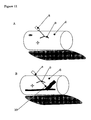
- Figure 11 shows the result of the VIS ( Figure 11 A) and NIR ( Figure 11 B ) images such as collected by the eyepiece 5 illustrated in Figure 10 .
- NIR and VIS beams are matched, shadows produced by irregular shapes at the tissue surface (e.g. skin structure, skin folds, molds, etc.) will also match in both wavelength ranges.
- the beams are oriented at a small angle with respect to the tissue region 6.
- skin folds etc. will produce sharp-edged shadows.
- Shiny areas that produce reflections and/or saturated pixels (marked as a star) will also match in both wavelength ranges. Due to the small angle, objects 8 that are brought towards the tissue surface 6 (e.g.
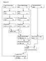
- a gradient edge enhancement step is applied for both spectral bands as will be illustrated with reference to Figure 16 (steps 13 and 14).
- Image VIS-J and NIR-J are obtained by filtering with a smoothing filter to suppress noise from camera image NIR and VIS. In the current implementation this is an averaging filter.
- two directional difference images Ix and Iy are calculated by means of a gradient filter. Currently this it performed with a Prewitt filter.
- VIS-G and NIR-G are made by Ix 2 + Iy 2 .
- VIS-G and NIR-G are clipped and normalized to 1 to obtain VIS-G' and NIR-G' (Steps 15 and 16).
- the images are complemented to 1-G' (Steps 17 and 18).
- VIS image and a pixel to pixel matching NIR image are acquired.
- the pixel coordinates that match both requirements are identified as superficial artifacts and are discarded by setting the pixel value to 1 in the corrected NIR edge image (Step 20).
- a corrected normalized NIR image (Step 22) is defined by discarding saturated image areas.
- the locations of all saturated pixels within the raw NIR image are identified.
- the edges are discarded by setting the pixel value to 1 (and thus completely ignoring edge information) is filled in, resulting in a second NIR-mask (step 23).
- This approach can be varied by including second, third etc. neighboring pixels.
- the raw IR image is used to provide "filled in” blood vessels; for example, by multiplying the 2nd NIR-mask with the 2nd corrected NIR image (step 24).
- this final enhancement mask now is multiplied with the luminosity component of the raw VIS image (which preferably is a color image) in step 25.
- the luminosity component of the raw VIS image which preferably is a color image
- the detection of purely superficial artifacts thus can be further improved when instead of taking all colors of the visible region into account, only the Blue spectral range is used for the VIS edge enhancement input. This is done in order to suppress the visibility of blood vessels. This effect of blue light is because in the visible range, the reflectivity of vessels for blue light is the nearest to skin (the maximum visible vessel contrast lies outside the blue range).
- the final enhancement mask may be selectively multiplied with e.g. only the Red and/or Green portion of the visible image (instead of the luminosity signal of the total visible color image).
- the user can switch to a mode that alters the image capturing sequence and allows the collection of an additional (second) NIR image within a selected region of interest (ROI).
- This ROI is virtually illuminated by photon injection just outside the ROI by means of EITHER a LED-array in contact with the tissue OR a pattern of laser dots or laser lines projected onto the tissue from a distance.
- EITHER a LED-array in contact with the tissue OR a pattern of laser dots or laser lines projected onto the tissue from a distance.
- the VIS and first NIR lighting are off.
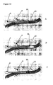
- a NIR-laser or NIR-LED is plugged onto a needle or catheter 8. Via a sterile window light is projected through or alongside the needle bore.
- the needle tip 10 illuminates the vessel interior wall 26 when the needle is in the vessel (see fig 13B ). If the needle punctures the distal vessel wall (see fig 13C ) a drastic change in illumination is seen.
- the light source clipped to the needle may be synchronized with the cameras. A flashing tip illumination may be beneficial.
Landscapes
- Health & Medical Sciences (AREA)
- Life Sciences & Earth Sciences (AREA)
- Engineering & Computer Science (AREA)
- Physics & Mathematics (AREA)
- Veterinary Medicine (AREA)
- Molecular Biology (AREA)
- Public Health (AREA)
- General Health & Medical Sciences (AREA)
- Biophysics (AREA)
- Pathology (AREA)
- Biomedical Technology (AREA)
- Heart & Thoracic Surgery (AREA)
- Medical Informatics (AREA)
- Animal Behavior & Ethology (AREA)
- Surgery (AREA)
- Theoretical Computer Science (AREA)
- General Physics & Mathematics (AREA)
- Computer Vision & Pattern Recognition (AREA)
- Vascular Medicine (AREA)
- Nuclear Medicine, Radiotherapy & Molecular Imaging (AREA)
- Radiology & Medical Imaging (AREA)
- Investigating Or Analysing Materials By Optical Means (AREA)
- Credit Cards Or The Like (AREA)
- Holo Graphy (AREA)
Abstract
Description
- The invention relates to a method of obtaining an image of buried structures in an object, in particular to imaging structures such as vascular structures in biological tissue by means of selective combining information derived from tissue images in the visible range and the infra-red range.
- A method describing such is disclosed in the international application
WO0115597 - While separating these two types of light, for instance by a known method of using polarized light and using the fact that specularly reflected light keeps its polarization direction, so that it can be filtered out by means of a polarizing filter, a substantial amount of the light is lost that is originating from the lower parts of the object, thus resulting in a loss of image brightness and resolution. This invites to the use of powerful light sources in order to receive sufficient light from the lower parts in the process of separating the two parts. However, especially in the area of imaging structures in live objects, there is a maximum amount of light that may be irradiated on the object.
-
WO01/50955 -
US2001/0037811 shows a probe for determining a circumference of a finger. Additionally, the joint is transilluminated for inspecting arthritis inflammation from a scattering analysis. This arrangement cannot be used for visually imaging body parts with a freedom comparable to the human eye. -
US 5,699,797 shows a method for sequentially recording of images at visible and near IR wavelengths and subsequent superposition of the images obtained thereby. The publication discusses the notion of two parallel light beams one, of visible, and the other of IR light. The elimination of artefacts in the IR image is not discussed. -
US 2003/210810-A1 suggests subtracting images taken at different wavelengths. -
WO 01/52735-A -
US 2002/181762-A1 shows a composite edge detection system having the edges of several images combined whereby the best focussed edges of each image are selected. No subtraction of edges is suggested. - The invention has as an object to provide an imaging technique that does not suffer from the afore described problems and that is able to provide an enhanced image of the underlying structure. Moreover, the invention has as an object to provide an imaging enhancement technique to enable a person to combine visual information and information of buried objects in one image.
- To achieve these and other goals, in one aspect, the invention offers a method according to the features of
claim 1. In another aspect, the invention offers a method according to the features ofclaim 13. - In particular, the invention is used while aligning said infrared light source with a visual light source; providing a first edge analysis of said infrared image; providing a second edge analysis of said visual image; comparing said first and second edge analysis; and discarding edges in said infrared image that are also detected in said second image. This offers the benefit of obtaining a "normal" visual image (as seen by the human eye), that is enhanced by identifying the underlying structure (detected using_infrared light) within the visual image while discarding false edges formed by shadowing or aliasing artifacts (e.g. shadows or reflections from a scalpel or needle). For instance, for surgical purposes, the method offers a convenient tool for deciding an optimal entry point in the object, for instance for cutting tissue or the like.
- Furthermore, by providing a camera for imaging visual and infrared-images; providing a bounded light source for partly irradiating said object by infrared light; partly irradiating said object by said bounded light source; imaging a non-irradiated area of said object by said camera to image said buried structure; and combining said buried structure image with a visual image of said object, infrared light incident on the image that is originating from a direct reflection is spatially filtered out of the image. The remaining partial image hence does not suffer from saturation effects due to direct illumination of specularly reflected light. In a preferred embodiment, a full image is provided by varying said partial irradiation in time so as to provide a full image by subsequent combining of said partial images.
- In a further preferred embodiment, said partial image is obtained by scanning a light beam over said object. In addition or alternatively, said partial image is obtained by subsequently irradiating said object by predetermined patterns. One particularly preferred embodiment comprises obtaining said partial image by alternatingly irradiating said object by a predetermined complementary patterns. For instance, in an embodiment said patterns may be matrix-patterns, line patterns, dot patterns, concentric or circular patterns.
- Further, preferably said object is irradiated only at predetermined positions that are spaced apart. By spacing the irradiation area and the light detection area, deeper parts of the buried structure may be enhanced.
- By alternatively illuminating said object, a full image may be provided, and wherein all areas of the object are irradiated in a time-dependent manner.
- The invention further offers particular benefits while using a CMOS-camera, since these camera's have a high degree of decorrelation of adjacent pixels. Thus, the effect of "blooming" is prevented, so that there is a high contrast between the directly reflected area (that is discarded) and the remaining area which receives diffuse light originating from deeper layers.
- Preferably, said edge-detection is performed by a gradient analysis of said first image. The invention offers a convenient embodiment when said images are provided stereoscopically. Furthermore, said first image may be spectrally analysed, and wherein said spectral analysis is projected into said second image. Furthermore, said spectral analysis may comprise a pulsatility analysis and/or a hart beat frequency analysis and/or respiratory frequency analysis. Such analysis thus offers a convenient non-contact tool for measuring body parameters of interest. Under "pulsatility analysis" is understood at least a determination of pulsating parts in the object of interest. The invention is further related to a method of enhancing imaging of buried structures in an object, comprising: as defined in
claim 14. Furthermore, the invention is related to a system as defined inclaim 16. - Further features and benefits will become apparent from the figures. In the figures:
-
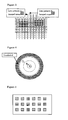
Figure 1 shows a schematic view of a scanning irradiating method of an object according to the invention; -
Figure 2 shows a schematic view of foton-migration in live tissue due to diffusion; -
Figure 3 shows an illumination method by illuminating an overlapping pattern on the object; -
Figure 4 shows an illumination method by illuminating a circular patterns on the object; -
Figure 5 shows an illumination method by illuminating a grid of patterns on the object; -
Figure 6 shows a testing arrangement for testing the apparatus according to the invention using one visible wavelength and two infrared wavelengths; -
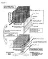
Figure 7 shows a series of analysis steps for processing and routing of data acquired from the arrangement ofFigure 6 ; -
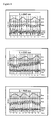
Figure 8 shows a spectral analysis of the pulsatile components in said image for light of three different wavelengths; -
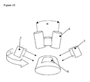
Figure 9 shows a simple vizor-like construction comprising the apparatus of the invention; -
Figure 10 shows the vizor-like construction ofFigure 9 in use; -
Figure 11 shows the VIS and NIR images collected by the eyepiece ofFigure 9 ; - Figure 12 illustrates the steps according to the method of the invention; and
-
Figure 13 shows a further embodiment of the inventive system including an infrared emitting puncture tool. -
Figure 1 shows an alternative to the above described polarization filtering method. This method comprises dynamic complementary lighting/scanning of alternating patterned image sections. This method does not require the use of polarization filters. It is based on the fact that photons entering biological tissue will strongly scatter within the tissue which partly results in backscattering. - Furthermore the viewed area is divided into parallel linear areas , which we will call "line sections". These line sections can be divided into even and
uneven line sections - Using a camera that has good anti-blooming specifications and allows the read-out of freely selectable rectangular pixel regions we then can acquire image information in a special sequence.
- During a certain period the bounded light source will light all
even line sections 1 and the camera will acquire image information from alluneven line sections 2. Here, the term bounded encompasses light that is bounded spatially, so that an illuminated object comprises, in a direction of view which is also a direction of illumination, non-illuminated areas which are not reached by the bounded light source. Such bounding can be typically reached by focusing, collimating or shielding the light source. Also various other light sources, such as laser lights (e.g. in combination with a holographic grating) and LEDs, can produce bounded lights. During the next period theuneven line sections 2 are lighted and the camera will acquire image information from the even line sections. This can either be done with a line camera that scans the entire tissue or with a normal camera that scans all even lines simultaneously and during the next period all uneven lines. - In
Figure 2 is illustrated how light diffused within the tissue can be used to image deeper parts of the object. Light enters the object at oneposition 1 and leaves the object at anotherposition 2. From the figure it becomes clear that light entering at further distanced positions can collect information from parts deeper within the object. By applying a variety of illumination patterns as will be further described with reference toFigure 3 - Figure 5 , illumination from "within" the object can be achieved, thus imaging deeper parts of the object. - To this end, in
Figure 3 , instead of even and uneven parallel lines shown inFigure 1 , alternate spatially shifted crossed line patterns can be used as lighting pattern whilst image acquisition occurs within the areas between the lines. It is also possible to first project an "even" dot pattern on the cross point ofline pattern 1 and then project an "uneven dot pattern on the cross sections ofline pattern 2. Also, inFigure 4 discrete concentric circular areas can be used. Satisfying results were obtained by a simple test of circular irradiation geometry disclosed inFigure 4 . A 6mm thick slice of pink foam (3M ethafoam) was laid upon the shielding pipe. On top of this foam slice a plastic office clamp was placed, with its' white plastic paper retaining slice laying across it. Finally a second slice of pink foam was laid on top. Outside the camera's field of view, a ring light injected photons of 660 nm, 810 nm and 940 nm into the foam, perpendicular to the foam surface. -
Figure 5 shows another embodiment, wherein said object is irradiated only at predetermined positions that are spaced apart. First areas 3 indicated with horizontal lines are irradiated in a first period;second areas 4 with vertical lines are irradiated in a second period. Such a spaced apart configuration is able to show deeper parts of the structure. By varying the spacing, lower and deeper parts of the object may be scanned. -
Figure 6 shows a testing arrangement, where an embodiment of the inventive method was tested using known markers such as an SP02 pulse oximeter, an ECG recording devise and a respiratory frequency monitor. The signals were recorded and sampled using the steps indicated inFigure 7 . This leads to a pixel by pixel time-analysis of intensity variation. The frames were sampled at a 100Hz Sample rate and the recorded respiration, ECG and plethismographic pulse output were compared. The outcome is illustrated for a variety of wavelengths inFigure 8 . It is clearly shown how well the measured variation of the camera matches with the other pulse signals. - A special configuration with added value is based upon two cameras (e.g. CCD or CMOS monochromatic or multiband) positioned at a certain distance from each other (e.g. eye-to-eye distance) thus stereoscopically viewing the same object (e.g. biological tissue), a dual channel electronic image processing device and two display devices placed in front of both eyes.
- Between each camera and the viewed object an additional optical system (maybe combining 2 channels) may be placed (e.g., a dual channel microscope, endoscope, colposcope, etc.) It is possible to incorporate a simple vizor-like construction 5 (see
Figure 9 ) so that the device can be either put in front of the eye or be positioned out of the viewing angle to allow normal sight. -
Figure 10 shows as an example thestereoscopic eyepiece 5 ofFigure 9 in use. For the eyepiece, a color camera can be applied with a bayer color filter pattern of which all filter colors are highly transparent in the NIR-range. Also a multi-layered camera chip (PatentWO 02/27804 WO 01 15597 A1 - The surface of the viewed
biological tissue region 6 is irradiated at an oblique angle from two opposite sides by twolight sources 7. These two sides need not to be aligned with the Left/Right axis of theeyepiece 5, but can be swiveled around in a plane perpendicular to the central axis of the joined cameras. - The
light sources 7 can be controlled to independently send out broadband white light in the visible wavelength range (VIS; 400 - 780nm) or narrowband light in the near infrared range (NIR; e.g. 920 nm) as well as in both ranges (VIS & NIR). Thelight sources 7 are carefully constructed so that the geometrical beam profiles of VIS and NIR are aligned resulting in identical shadowing in the VIS and NIR images. As an alternative also a surgical stereo microscope or an endoscopic dual channel camera (as used in stereoscopic robot surgery) with two side fiber light guides can be used to collect the images. -
Figure 11 shows the result of the VIS (Figure 11 A) and NIR (Figure 11 B ) images such as collected by theeyepiece 5 illustrated inFigure 10 . Since NIR and VIS beams are matched, shadows produced by irregular shapes at the tissue surface (e.g. skin structure, skin folds, molds, etc.) will also match in both wavelength ranges. In the embodiment disclosed, the beams are oriented at a small angle with respect to thetissue region 6. As a result, skin folds etc. will produce sharp-edged shadows. Shiny areas that produce reflections and/or saturated pixels (marked as a star) will also match in both wavelength ranges. Due to the small angle, objects 8 that are brought towards the tissue surface 6 (e.g. needles, scalpels, probes, etc.) will produce two separate shadows. These shadows will meet and typically form a "V"pattern 9 when an object touches the surface. If e.g. a needle punctures the surface, then theneedle tip 10 will quickly disappear from the VIS image (Figure 11 A) . On the NIR image (Figure 11 B) however, thetip 10 will remain visible within the tissue 6 (see figure). - On the VIS image (
Figure 11 A) , only very superficial blood vessels will be visible, especially if the texture of the vessel deforms the skin. On the NIR image, however, blood vessels will be visible much better (even blood vessels at a depth of a few millimeters below the surface). Since skin pigment (melanin) has a very low absorbance within the NIR region this good NIR visibility will also be the case with dark skinned persons (also molds will lose their dark color). - After obtaining the NIR and VIS images in
steps Figure 16 (steps 13 and 14). Image VIS-J and NIR-J are obtained by filtering with a smoothing filter to suppress noise from camera image NIR and VIS. In the current implementation this is an averaging filter. From each smoothed images VIS-J and NIR-J, two directional difference images Ix and Iy are calculated by means of a gradient filter. Currently this it performed with a Prewitt filter. - Next edge gradient images VIS-G and NIR-G are made by

Steps 15 and 16). Finally the images are complemented to 1-G' (Steps 17 and 18). - For a given tissue region a VIS image and a pixel to pixel matching NIR image are acquired.
- The images from both spectral bands are subjected to an identical edge enhancement algorithm (see above), producing normalized NIR-edge and VIS-edge grayscale images so that edges are encoded black (0 = black and 1 = white; note that this is the negative of normal edge enhanced results).
- Now corresponding edges in the NIR and VIS image are determined (Step 19) according to a pixel by pixel criterion:
- NIR-edge-pixel < NIR_Treshold AND VIS-edge-pixel < VIS_Treshold (Thresholds are both software configurable)
- By combining information from both spectral regions, the pixel coordinates that match both requirements are identified as superficial artifacts and are discarded by setting the pixel value to 1 in the corrected NIR edge image (Step 20).
- By doing the same in the raw NIR image after normalizing (Step 21) (no edge enhancement) a corrected normalized NIR image (Step 22) is defined by discarding saturated image areas.
- To this end, the locations of all saturated pixels within the raw NIR image (e.g. 256 for an 8-bit image) are identified. For all pixels within the 1st NIR-mask that are saturated or a direct neighbors of a saturated pixel, the edges are discarded by setting the pixel value to 1 (and thus completely ignoring edge information) is filled in, resulting in a second NIR-mask (step 23).
- False edges resulting from saturated pixels are thus removed and the 2nd NIR-mask now contains the boundaries of subcutaneous blood vessels (and eventual other buried contrasting structures).
- This approach can be varied by including second, third etc. neighboring pixels.
- In a preferred mode, the raw IR image is used to provide "filled in" blood vessels; for example, by multiplying the 2nd NIR-mask with the 2nd corrected NIR image (step 24). The amount of fill-in colorization can be varied with a user adjustable exponent N :

- Finally, this final enhancement mask now is multiplied with the luminosity component of the raw VIS image (which preferably is a color image) in
step 25. In this way only contrast information that truly originates from below the tissue surface is projected into the VIS image. If we look at the previous drawings with a needle inserted in tissue it is clear that these criteria will lead to superimposing only the buried needle tip upon the VIS image. Shadows, wrinkles, reflections and the edges of molds will not be enhanced. - The detection of purely superficial artifacts thus can be further improved when instead of taking all colors of the visible region into account, only the Blue spectral range is used for the VIS edge enhancement input. This is done in order to suppress the visibility of blood vessels. This effect of blue light is because in the visible range, the reflectivity of vessels for blue light is the nearest to skin (the maximum visible vessel contrast lies outside the blue range). As another optional refinement the final enhancement mask may be selectively multiplied with e.g. only the Red and/or Green portion of the visible image (instead of the luminosity signal of the total visible color image).
- When an interesting tissue portion is spotted, the user can switch to a mode that alters the image capturing sequence and allows the collection of an additional (second) NIR image within a selected region of interest (ROI). This ROI is virtually illuminated by photon injection just outside the ROI by means of EITHER a LED-array in contact with the tissue OR a pattern of laser dots or laser lines projected onto the tissue from a distance. During acquisition of this second NIR image the VIS and first NIR lighting are off.
- In this way information obtained using two types of lighting geometries for the same wavelength range can be combined. This can be done with or without also using VIS and flashing needle tip lighting as will be illustrated with reference to
Figure 13 . - In
Figure 13 a NIR-laser or NIR-LED is plugged onto a needle orcatheter 8. Via a sterile window light is projected through or alongside the needle bore. In this way theneedle tip 10 illuminates the vesselinterior wall 26 when the needle is in the vessel (seefig 13B ). If the needle punctures the distal vessel wall (seefig 13C ) a drastic change in illumination is seen. The light source clipped to the needle may be synchronized with the cameras. A flashing tip illumination may be beneficial. - Although in the preceding the invention has been further illustrated with reference to the drawings and the description it will be clear that the invention is not limited thereto and that these embodiments are only disclosed for the purpose of illustration. Variations and modifications thereto are within the scope of the invention as defined in the annexed claims.
Claims (18)
- A method of obtaining an image of buried structures (8) in an object, comprising:- providing a camera (5) for imaging visual and infrared-images;- providing a bounded infrared light source;- partly irradiating said object by said bounded light source;- imaging a non-irradiated area (2) of said object by said camera to image said buried structure; and- combining said buried structure image with a visual image of said object- aligning said infrared light source with a visual light source (7);characterized in that the method further comprises- providing a first edge analysis of said infrared image;- providing a second edge analysis of said visual image;- comparing said first and second edge analysis; and- discarding edges in said infrared image that are also detected in said second image.
- A method according to claim 1 wherein said irradiation is varied in time so as to provide a full image by subsequent combining of partial images.
- A method according to claim 1 or 2, wherein said image is obtained by scanning a light beam over said object.
- A method according to claim 1 or 2, wherein said image is obtained by subsequently irradiating said object by predetermined patterns (1,2).
- A method according to claim 4, wherein said partial image is obtained by alternatingly irradiating said object by said predetermined complementary patterns.
- A method according to claim 4 or 5, wherein said patterns are matrix-patterns, line patterns, dot patterns or concentric patterns (T1, T2, T3).
- A method according to any of claims 4-6, wherein said object is irradiated only at predetermined positions that are spaced apart.
- A method according to any of claims 1-7, wherein said image is obtained by a CMOS-camera.
- A method according to claim 1, further comprising:- correcting said first image to discard saturated image areas.
- A method according to any of the preceding claims, wherein said images are provided stereoscopically.
- A method according to any of the preceding claims, wherein said first image is spectrally analysed, and wherein said spectral analysis is projected into said second image.
- A method according to claim 11, wherein said spectral analysis comprises a pulsatility analysis and/or a heart beat frequency analysis and/or respiratory frequency analysis.
- System for obtaining an image of buried structures in an object, comprising:- a bounded infrared light source (7), the light source aligned with a visual light source (7), for partly irradiating said object by light;- a camera device (5) arranged for obtaining a first buried structure image in a non-irradiated area of the object and for obtaining a second visual image of said object; and- a processing device arranged to:○ providing a gradient analysis of said first buried structure image in order to detect the edges of said buried structure; and for providing a gradient analysis of said second visual image;○ comparing the gradient analysis of said second visual image with the gradient analysis of said first buried structure image;○ discarding edges in said first buried structure image that are also detected in said second visual image; and○ combining said first and second images for defining edges of said buried structure in said visual image.
- A system according to claim 13 further comprising:- a puncture tool (8) for puncturing human tissue; and- an IR light source (10) provided in said puncture tool.
- A system according to claim 14, wherein said IR light is aligned along said puncture tool.
- A system according to claim 14 or 15, wherein said IR light is provided in a tip of said puncture tool.
- A system according to any of claims 14-16, wherein said puncture tool is provided with an IR radiating coating.
- A system according to any of claims 14-17, wherein the IR light source and the bounded light source are alternatingly activated.
Priority Applications (1)
| Application Number | Priority Date | Filing Date | Title |
|---|---|---|---|
| EP05710889A EP1729629B1 (en) | 2004-02-19 | 2005-02-15 | Imaging of buried structures |
Applications Claiming Priority (3)
| Application Number | Priority Date | Filing Date | Title |
|---|---|---|---|
| EP04075541A EP1566142A1 (en) | 2004-02-19 | 2004-02-19 | Imaging of buried structures |
| EP05710889A EP1729629B1 (en) | 2004-02-19 | 2005-02-15 | Imaging of buried structures |
| PCT/NL2005/000108 WO2005079662A1 (en) | 2004-02-19 | 2005-02-15 | Imaging of buried structures |
Publications (2)
| Publication Number | Publication Date |
|---|---|
| EP1729629A1 EP1729629A1 (en) | 2006-12-13 |
| EP1729629B1 true EP1729629B1 (en) | 2009-11-11 |
Family
ID=34707381
Family Applications (2)
| Application Number | Title | Priority Date | Filing Date |
|---|---|---|---|
| EP04075541A Withdrawn EP1566142A1 (en) | 2004-02-19 | 2004-02-19 | Imaging of buried structures |
| EP05710889A Expired - Lifetime EP1729629B1 (en) | 2004-02-19 | 2005-02-15 | Imaging of buried structures |
Family Applications Before (1)
| Application Number | Title | Priority Date | Filing Date |
|---|---|---|---|
| EP04075541A Withdrawn EP1566142A1 (en) | 2004-02-19 | 2004-02-19 | Imaging of buried structures |
Country Status (7)
| Country | Link |
|---|---|
| US (1) | US8630465B2 (en) |
| EP (2) | EP1566142A1 (en) |
| JP (1) | JP4739242B2 (en) |
| AT (1) | ATE447880T1 (en) |
| DE (1) | DE602005017588D1 (en) |
| ES (1) | ES2336577T3 (en) |
| WO (1) | WO2005079662A1 (en) |
Families Citing this family (47)
| Publication number | Priority date | Publication date | Assignee | Title |
|---|---|---|---|---|
| US8620410B2 (en) | 2002-03-12 | 2013-12-31 | Beth Israel Deaconess Medical Center | Multi-channel medical imaging system |
| WO2003100925A2 (en) | 2002-05-22 | 2003-12-04 | Beth Israel Deaconess Medical Center | Device for wavelength-selective imaging |
| US8473035B2 (en) | 2003-09-15 | 2013-06-25 | Beth Israel Deaconess Medical Center | Medical imaging systems |
| US9750425B2 (en) * | 2004-03-23 | 2017-09-05 | Dune Medical Devices Ltd. | Graphical user interfaces (GUI), methods and apparatus for data presentation |
| US20060241495A1 (en) * | 2005-03-23 | 2006-10-26 | Eastman Kodak Company | Wound healing monitoring and treatment |
| US8478386B2 (en) | 2006-01-10 | 2013-07-02 | Accuvein Inc. | Practitioner-mounted micro vein enhancer |
| US10813588B2 (en) | 2006-01-10 | 2020-10-27 | Accuvein, Inc. | Micro vein enhancer |
| US12408865B2 (en) | 2006-01-10 | 2025-09-09 | Accuvein Inc. | Vein imaging device with differential image resolution at the center and the extremities of the vein image |
| US11253198B2 (en) | 2006-01-10 | 2022-02-22 | Accuvein, Inc. | Stand-mounted scanned laser vein contrast enhancer |
| US8838210B2 (en) | 2006-06-29 | 2014-09-16 | AccuView, Inc. | Scanned laser vein contrast enhancer using a single laser |
| US9854977B2 (en) | 2006-01-10 | 2018-01-02 | Accuvein, Inc. | Scanned laser vein contrast enhancer using a single laser, and modulation circuitry |
| US12295744B2 (en) | 2006-01-10 | 2025-05-13 | Accuvein, Inc. | Micro vein enhancer with two lasers and two optical detectors configured for removing surface topology |
| US10238294B2 (en) | 2006-06-29 | 2019-03-26 | Accuvein, Inc. | Scanned laser vein contrast enhancer using one laser |
| US11278240B2 (en) | 2006-01-10 | 2022-03-22 | Accuvein, Inc. | Trigger-actuated laser vein contrast enhancer |
| US12089951B2 (en) | 2006-01-10 | 2024-09-17 | AccuVeiw, Inc. | Scanned laser vein contrast enhancer with scanning correlated to target distance |
| US12471844B2 (en) | 2006-06-29 | 2025-11-18 | Accuvein, Inc. | Scanned laser vein contrast enhancer with full stopping of scanner movement during scan line reversals |
| US8489178B2 (en) | 2006-06-29 | 2013-07-16 | Accuvein Inc. | Enhanced laser vein contrast enhancer with projection of analyzed vein data |
| US9492117B2 (en) | 2006-01-10 | 2016-11-15 | Accuvein, Inc. | Practitioner-mounted micro vein enhancer |
| WO2007119199A1 (en) | 2006-04-18 | 2007-10-25 | Koninklijke Philips Electronics N.V. | Optical measurement device |
| US8463364B2 (en) | 2009-07-22 | 2013-06-11 | Accuvein Inc. | Vein scanner |
| US8730321B2 (en) | 2007-06-28 | 2014-05-20 | Accuvein, Inc. | Automatic alignment of a contrast enhancement system |
| US8594770B2 (en) | 2006-06-29 | 2013-11-26 | Accuvein, Inc. | Multispectral detection and presentation of an object's characteristics |
| JP5073996B2 (en) * | 2006-09-20 | 2012-11-14 | オリンパス株式会社 | Image processing device |
| IL180469A0 (en) * | 2006-12-31 | 2007-06-03 | Gil Shetrit | Vascular access system and method |
| JP5594788B2 (en) * | 2008-12-05 | 2014-09-24 | アケソ メディカル イメージング ビー. ヴィ. | Method and apparatus for optical detection of joint condition |
| US8503712B2 (en) * | 2008-12-31 | 2013-08-06 | Motorola Mobility Llc | Method and apparatus for determining blood oxygenation using a mobile communication device |
| NL2002544C2 (en) * | 2009-02-18 | 2010-08-19 | Bio Photonics Holding B V | Pixel-to-pixel aligned multispectral imaging & spatial light modulation through optical instruments. |
| US9061109B2 (en) | 2009-07-22 | 2015-06-23 | Accuvein, Inc. | Vein scanner with user interface |
| FR2969292A1 (en) | 2010-12-17 | 2012-06-22 | Commissariat Energie Atomique | METHOD AND DEVICE FOR OPTICAL EXAMINATION IN REFLECTION GEOMETRY |
| US9625258B2 (en) | 2011-06-06 | 2017-04-18 | 3Shape A/S | Dual-resolution 3D scanner |
| US8879848B2 (en) * | 2011-07-27 | 2014-11-04 | National Instruments Corporation | Machine vision based automatic maximal clamp measurement tool |
| US20150051521A1 (en) * | 2012-03-13 | 2015-02-19 | Koninklijke Philips N.V. | Cardiopulmonary resuscitation apparatus comprising a physiological sensor |
| US8897522B2 (en) * | 2012-05-30 | 2014-11-25 | Xerox Corporation | Processing a video for vascular pattern detection and cardiac function analysis |
| US9072426B2 (en) | 2012-08-02 | 2015-07-07 | AccuVein, Inc | Device for detecting and illuminating vasculature using an FPGA |
| US10376147B2 (en) | 2012-12-05 | 2019-08-13 | AccuVeiw, Inc. | System and method for multi-color laser imaging and ablation of cancer cells using fluorescence |
| CN203289635U (en) | 2013-05-10 | 2013-11-13 | 瑞声声学科技(深圳)有限公司 | Spring plate and multifunctional sounder applying spring plate |
| JP6261994B2 (en) * | 2014-01-28 | 2018-01-17 | 三菱重工業株式会社 | Image correction method, inspection method and inspection apparatus using the same |
| US9990730B2 (en) | 2014-03-21 | 2018-06-05 | Fluke Corporation | Visible light image with edge marking for enhancing IR imagery |
| JP6511777B2 (en) * | 2014-11-10 | 2019-05-15 | セイコーエプソン株式会社 | Image processing apparatus, image processing method and program |
| CN106236060B (en) * | 2015-06-04 | 2021-04-09 | 松下知识产权经营株式会社 | Biological information detection device |
| US10152811B2 (en) | 2015-08-27 | 2018-12-11 | Fluke Corporation | Edge enhancement for thermal-visible combined images and cameras |
| CN114795151A (en) * | 2016-06-30 | 2022-07-29 | 松下知识产权经营株式会社 | Method and system |
| CN116269261B (en) | 2016-12-01 | 2025-10-28 | 松下知识产权经营株式会社 | Biological information processing method and biological information processing system |
| TWI662940B (en) * | 2018-06-01 | 2019-06-21 | 廣達電腦股份有限公司 | Image capturing device |
| JP7247501B2 (en) * | 2018-09-21 | 2023-03-29 | 富士フイルムビジネスイノベーション株式会社 | Image processing device and program |
| NL2023688B1 (en) | 2019-08-22 | 2021-04-21 | I Med Tech B V | Binocular device |
| CN111879791B (en) * | 2020-07-30 | 2023-06-20 | 西湖大学 | Machine vision system and method for enhancing raised features on pattern surface |
Family Cites Families (12)
| Publication number | Priority date | Publication date | Assignee | Title |
|---|---|---|---|---|
| US4555179A (en) * | 1982-11-08 | 1985-11-26 | John Langerholc | Detection and imaging of objects in scattering media by light irradiation |
| US5137355A (en) * | 1988-06-08 | 1992-08-11 | The Research Foundation Of State University Of New York | Method of imaging a random medium |
| US5699797A (en) * | 1992-10-05 | 1997-12-23 | Dynamics Imaging, Inc. | Method of investigation of microcirculation functional dynamics of physiological liquids in skin and apparatus for its realization |
| US6032070A (en) * | 1995-06-07 | 2000-02-29 | University Of Arkansas | Method and apparatus for detecting electro-magnetic reflection from biological tissue |
| NL1012943C2 (en) * | 1999-08-31 | 2001-03-01 | Tno | Detector and imaging device for determining concentration ratios. |
| AU2001229442A1 (en) * | 2000-01-14 | 2001-07-24 | Stephen T Flock | Improved endoscopic imaging and treatment of anatomic structures |
| AU3042201A (en) * | 2000-01-17 | 2001-07-31 | Stiftung Zur Forderung Der Erforschung Und Behandlung Kindlicher Leukamien (kinderleukamiestiftung) | Improved visualisation of venous injection sites |
| DE10004989B4 (en) * | 2000-02-04 | 2006-11-02 | Siemens Ag | Method and device for arthritis diagnosis |
| US20020035317A1 (en) * | 2000-08-04 | 2002-03-21 | Photonify Technologies | Optical imaging system with movable scanning unit |
| US7058233B2 (en) * | 2001-05-30 | 2006-06-06 | Mitutoyo Corporation | Systems and methods for constructing an image having an extended depth of field |
| US7158660B2 (en) * | 2002-05-08 | 2007-01-02 | Gee Jr James W | Method and apparatus for detecting structures of interest |
| US7372985B2 (en) * | 2003-08-15 | 2008-05-13 | Massachusetts Institute Of Technology | Systems and methods for volumetric tissue scanning microscopy |
-
2004
- 2004-02-19 EP EP04075541A patent/EP1566142A1/en not_active Withdrawn
-
2005
- 2005-02-15 WO PCT/NL2005/000108 patent/WO2005079662A1/en not_active Ceased
- 2005-02-15 ES ES05710889T patent/ES2336577T3/en not_active Expired - Lifetime
- 2005-02-15 US US10/598,077 patent/US8630465B2/en not_active Expired - Fee Related
- 2005-02-15 AT AT05710889T patent/ATE447880T1/en active
- 2005-02-15 DE DE602005017588T patent/DE602005017588D1/en not_active Expired - Lifetime
- 2005-02-15 JP JP2006554039A patent/JP4739242B2/en not_active Expired - Fee Related
- 2005-02-15 EP EP05710889A patent/EP1729629B1/en not_active Expired - Lifetime
Also Published As
| Publication number | Publication date |
|---|---|
| US20090028461A1 (en) | 2009-01-29 |
| WO2005079662A1 (en) | 2005-09-01 |
| JP2007522869A (en) | 2007-08-16 |
| ES2336577T3 (en) | 2010-04-14 |
| EP1729629A1 (en) | 2006-12-13 |
| JP4739242B2 (en) | 2011-08-03 |
| DE602005017588D1 (en) | 2009-12-24 |
| EP1566142A1 (en) | 2005-08-24 |
| US8630465B2 (en) | 2014-01-14 |
| ATE447880T1 (en) | 2009-11-15 |
Similar Documents
| Publication | Publication Date | Title |
|---|---|---|
| US8630465B2 (en) | Imaging of buried structures | |
| CN105848566B (en) | Device for non-invasive detection of predetermined biological structures | |
| US5408998A (en) | Video based tissue oximetry | |
| US6775565B1 (en) | Imaging apparatus for displaying concentration ratios | |
| JP6763719B2 (en) | Biometric information measuring device, biometric information measuring method and program | |
| US20100061598A1 (en) | Apparatus and method for recognizing subcutaneous vein pattern | |
| US20080062429A1 (en) | Low coherence dental oct imaging | |
| US20110304705A1 (en) | Method and apparatus for imaging tissue topography | |
| JP7374280B2 (en) | Endoscope device, endoscope processor, and method of operating the endoscope device | |
| US10159418B2 (en) | Information obtaining apparatus, image capturing apparatus, and method for obtaining information | |
| CN215305781U (en) | Apparatus for identifying parathyroid gland position and evaluating parathyroid gland survival rate | |
| EP3393341B1 (en) | Device and method for acquisition of medical images for the analysis of ulcers | |
| US11445947B2 (en) | Methods and apparatus for measuring blood oxygenation of tissue | |
| WO2021059889A1 (en) | Endoscopic system | |
| JP2012010776A (en) | Tomographic image processing apparatus and method, and optical interference tomographic image diagnostic apparatus | |
| JP4109132B2 (en) | Fluorescence determination device | |
| Wieringa et al. | Pulse oxigraphy demonstrated on a phantom with arterial and venous regions | |
| KR20220098578A (en) | Apparatus for Intraoperative Identification and Viability Assessment of Tissue and Method Using the Same | |
| Awais et al. | Analysis of auto-fluorescence images for automatic detection of abnormalities in oral cavity | |
| CN113424048A (en) | Tissue detection system and method of use | |
| CN114041737B (en) | Imaging device applied to endoscope | |
| KR101669411B1 (en) | System and Method For Fabrication Skin and Teeth Analyzer | |
| JP2012050598A (en) | Imaging and displaying method and apparatus | |
| CN118806231A (en) | Skin detection device with display screen | |
| KR101047902B1 (en) | Skin condition measuring device |
Legal Events
| Date | Code | Title | Description |
|---|---|---|---|
| PUAI | Public reference made under article 153(3) epc to a published international application that has entered the european phase |
Free format text: ORIGINAL CODE: 0009012 |
|
| 17P | Request for examination filed |
Effective date: 20060904 |
|
| AK | Designated contracting states |
Kind code of ref document: A1 Designated state(s): AT BE BG CH CY CZ DE DK EE ES FI FR GB GR HU IE IS IT LI LT LU MC NL PL PT RO SE SI SK TR |
|
| 17Q | First examination report despatched |
Effective date: 20061211 |
|
| DAX | Request for extension of the european patent (deleted) | ||
| GRAP | Despatch of communication of intention to grant a patent |
Free format text: ORIGINAL CODE: EPIDOSNIGR1 |
|
| GRAS | Grant fee paid |
Free format text: ORIGINAL CODE: EPIDOSNIGR3 |
|
| GRAA | (expected) grant |
Free format text: ORIGINAL CODE: 0009210 |
|
| AK | Designated contracting states |
Kind code of ref document: B1 Designated state(s): AT BE BG CH CY CZ DE DK EE ES FI FR GB GR HU IE IS IT LI LT LU MC NL PL PT RO SE SI SK TR |
|
| REG | Reference to a national code |
Ref country code: GB Ref legal event code: FG4D |
|
| REG | Reference to a national code |
Ref country code: CH Ref legal event code: EP |
|
| REG | Reference to a national code |
Ref country code: IE Ref legal event code: FG4D |
|
| REF | Corresponds to: |
Ref document number: 602005017588 Country of ref document: DE Date of ref document: 20091224 Kind code of ref document: P |
|
| REG | Reference to a national code |
Ref country code: SE Ref legal event code: TRGR |
|
| REG | Reference to a national code |
Ref country code: CH Ref legal event code: NV Representative=s name: PATENTANWAELTE SCHAAD, BALASS, MENZL & PARTNER AG |
|
| REG | Reference to a national code |
Ref country code: ES Ref legal event code: FG2A Ref document number: 2336577 Country of ref document: ES Kind code of ref document: T3 |
|
| LTIE | Lt: invalidation of european patent or patent extension |
Effective date: 20091111 |
|
| PG25 | Lapsed in a contracting state [announced via postgrant information from national office to epo] |
Ref country code: PT Free format text: LAPSE BECAUSE OF FAILURE TO SUBMIT A TRANSLATION OF THE DESCRIPTION OR TO PAY THE FEE WITHIN THE PRESCRIBED TIME-LIMIT Effective date: 20100311 Ref country code: IS Free format text: LAPSE BECAUSE OF FAILURE TO SUBMIT A TRANSLATION OF THE DESCRIPTION OR TO PAY THE FEE WITHIN THE PRESCRIBED TIME-LIMIT Effective date: 20100311 Ref country code: LT Free format text: LAPSE BECAUSE OF FAILURE TO SUBMIT A TRANSLATION OF THE DESCRIPTION OR TO PAY THE FEE WITHIN THE PRESCRIBED TIME-LIMIT Effective date: 20091111 |
|
| PG25 | Lapsed in a contracting state [announced via postgrant information from national office to epo] |
Ref country code: SI Free format text: LAPSE BECAUSE OF FAILURE TO SUBMIT A TRANSLATION OF THE DESCRIPTION OR TO PAY THE FEE WITHIN THE PRESCRIBED TIME-LIMIT Effective date: 20091111 Ref country code: PL Free format text: LAPSE BECAUSE OF FAILURE TO SUBMIT A TRANSLATION OF THE DESCRIPTION OR TO PAY THE FEE WITHIN THE PRESCRIBED TIME-LIMIT Effective date: 20091111 Ref country code: CY Free format text: LAPSE BECAUSE OF FAILURE TO SUBMIT A TRANSLATION OF THE DESCRIPTION OR TO PAY THE FEE WITHIN THE PRESCRIBED TIME-LIMIT Effective date: 20091111 |
|
| PG25 | Lapsed in a contracting state [announced via postgrant information from national office to epo] |
Ref country code: RO Free format text: LAPSE BECAUSE OF FAILURE TO SUBMIT A TRANSLATION OF THE DESCRIPTION OR TO PAY THE FEE WITHIN THE PRESCRIBED TIME-LIMIT Effective date: 20091111 Ref country code: EE Free format text: LAPSE BECAUSE OF FAILURE TO SUBMIT A TRANSLATION OF THE DESCRIPTION OR TO PAY THE FEE WITHIN THE PRESCRIBED TIME-LIMIT Effective date: 20091111 Ref country code: DK Free format text: LAPSE BECAUSE OF FAILURE TO SUBMIT A TRANSLATION OF THE DESCRIPTION OR TO PAY THE FEE WITHIN THE PRESCRIBED TIME-LIMIT Effective date: 20091111 Ref country code: BG Free format text: LAPSE BECAUSE OF FAILURE TO SUBMIT A TRANSLATION OF THE DESCRIPTION OR TO PAY THE FEE WITHIN THE PRESCRIBED TIME-LIMIT Effective date: 20100211 |
|
| PG25 | Lapsed in a contracting state [announced via postgrant information from national office to epo] |
Ref country code: CZ Free format text: LAPSE BECAUSE OF FAILURE TO SUBMIT A TRANSLATION OF THE DESCRIPTION OR TO PAY THE FEE WITHIN THE PRESCRIBED TIME-LIMIT Effective date: 20091111 Ref country code: SK Free format text: LAPSE BECAUSE OF FAILURE TO SUBMIT A TRANSLATION OF THE DESCRIPTION OR TO PAY THE FEE WITHIN THE PRESCRIBED TIME-LIMIT Effective date: 20091111 |
|
| PLBE | No opposition filed within time limit |
Free format text: ORIGINAL CODE: 0009261 |
|
| STAA | Information on the status of an ep patent application or granted ep patent |
Free format text: STATUS: NO OPPOSITION FILED WITHIN TIME LIMIT |
|
| 26N | No opposition filed |
Effective date: 20100812 |
|
| PG25 | Lapsed in a contracting state [announced via postgrant information from national office to epo] |
Ref country code: MC Free format text: LAPSE BECAUSE OF NON-PAYMENT OF DUE FEES Effective date: 20100301 Ref country code: GR Free format text: LAPSE BECAUSE OF FAILURE TO SUBMIT A TRANSLATION OF THE DESCRIPTION OR TO PAY THE FEE WITHIN THE PRESCRIBED TIME-LIMIT Effective date: 20100212 |
|
| PG25 | Lapsed in a contracting state [announced via postgrant information from national office to epo] |
Ref country code: LU Free format text: LAPSE BECAUSE OF NON-PAYMENT OF DUE FEES Effective date: 20100215 Ref country code: HU Free format text: LAPSE BECAUSE OF FAILURE TO SUBMIT A TRANSLATION OF THE DESCRIPTION OR TO PAY THE FEE WITHIN THE PRESCRIBED TIME-LIMIT Effective date: 20100512 |
|
| PG25 | Lapsed in a contracting state [announced via postgrant information from national office to epo] |
Ref country code: TR Free format text: LAPSE BECAUSE OF FAILURE TO SUBMIT A TRANSLATION OF THE DESCRIPTION OR TO PAY THE FEE WITHIN THE PRESCRIBED TIME-LIMIT Effective date: 20091111 |
|
| PGFP | Annual fee paid to national office [announced via postgrant information from national office to epo] |
Ref country code: NL Payment date: 20140218 Year of fee payment: 10 Ref country code: SE Payment date: 20140218 Year of fee payment: 10 Ref country code: FI Payment date: 20140212 Year of fee payment: 10 Ref country code: IE Payment date: 20140221 Year of fee payment: 10 Ref country code: CH Payment date: 20140218 Year of fee payment: 10 |
|
| PGFP | Annual fee paid to national office [announced via postgrant information from national office to epo] |
Ref country code: AT Payment date: 20140212 Year of fee payment: 10 Ref country code: IT Payment date: 20140226 Year of fee payment: 10 Ref country code: BE Payment date: 20140218 Year of fee payment: 10 Ref country code: ES Payment date: 20140226 Year of fee payment: 10 |
|
| PG25 | Lapsed in a contracting state [announced via postgrant information from national office to epo] |
Ref country code: BE Free format text: LAPSE BECAUSE OF NON-PAYMENT OF DUE FEES Effective date: 20150228 |
|
| REG | Reference to a national code |
Ref country code: NL Ref legal event code: V1 Effective date: 20150901 |
|
| REG | Reference to a national code |
Ref country code: SE Ref legal event code: EUG |
|
| PG25 | Lapsed in a contracting state [announced via postgrant information from national office to epo] |
Ref country code: NL Free format text: LAPSE BECAUSE OF NON-PAYMENT OF DUE FEES Effective date: 20150901 |
|
| REG | Reference to a national code |
Ref country code: CH Ref legal event code: PL |
|
| REG | Reference to a national code |
Ref country code: AT Ref legal event code: MM01 Ref document number: 447880 Country of ref document: AT Kind code of ref document: T Effective date: 20150215 |
|
| PG25 | Lapsed in a contracting state [announced via postgrant information from national office to epo] |
Ref country code: LI Free format text: LAPSE BECAUSE OF NON-PAYMENT OF DUE FEES Effective date: 20150228 Ref country code: FI Free format text: LAPSE BECAUSE OF NON-PAYMENT OF DUE FEES Effective date: 20150215 Ref country code: CH Free format text: LAPSE BECAUSE OF NON-PAYMENT OF DUE FEES Effective date: 20150228 |
|
| REG | Reference to a national code |
Ref country code: IE Ref legal event code: MM4A |
|
| PG25 | Lapsed in a contracting state [announced via postgrant information from national office to epo] |
Ref country code: AT Free format text: LAPSE BECAUSE OF NON-PAYMENT OF DUE FEES Effective date: 20150215 Ref country code: SE Free format text: LAPSE BECAUSE OF NON-PAYMENT OF DUE FEES Effective date: 20150216 |
|
| PG25 | Lapsed in a contracting state [announced via postgrant information from national office to epo] |
Ref country code: IT Free format text: LAPSE BECAUSE OF NON-PAYMENT OF DUE FEES Effective date: 20150215 |
|
| PG25 | Lapsed in a contracting state [announced via postgrant information from national office to epo] |
Ref country code: IE Free format text: LAPSE BECAUSE OF NON-PAYMENT OF DUE FEES Effective date: 20150215 |
|
| REG | Reference to a national code |
Ref country code: FR Ref legal event code: PLFP Year of fee payment: 12 |
|
| REG | Reference to a national code |
Ref country code: ES Ref legal event code: FD2A Effective date: 20160603 |
|
| PG25 | Lapsed in a contracting state [announced via postgrant information from national office to epo] |
Ref country code: ES Free format text: LAPSE BECAUSE OF NON-PAYMENT OF DUE FEES Effective date: 20150216 |
|
| REG | Reference to a national code |
Ref country code: FR Ref legal event code: PLFP Year of fee payment: 13 |
|
| REG | Reference to a national code |
Ref country code: FR Ref legal event code: PLFP Year of fee payment: 14 |
|
| PGFP | Annual fee paid to national office [announced via postgrant information from national office to epo] |
Ref country code: DE Payment date: 20190219 Year of fee payment: 15 Ref country code: GB Payment date: 20190218 Year of fee payment: 15 |
|
| PGFP | Annual fee paid to national office [announced via postgrant information from national office to epo] |
Ref country code: FR Payment date: 20190220 Year of fee payment: 15 |
|
| REG | Reference to a national code |
Ref country code: DE Ref legal event code: R119 Ref document number: 602005017588 Country of ref document: DE |
|
| GBPC | Gb: european patent ceased through non-payment of renewal fee |
Effective date: 20200215 |
|
| PG25 | Lapsed in a contracting state [announced via postgrant information from national office to epo] |
Ref country code: FR Free format text: LAPSE BECAUSE OF NON-PAYMENT OF DUE FEES Effective date: 20200229 Ref country code: GB Free format text: LAPSE BECAUSE OF NON-PAYMENT OF DUE FEES Effective date: 20200215 Ref country code: DE Free format text: LAPSE BECAUSE OF NON-PAYMENT OF DUE FEES Effective date: 20200901 |