EP1729368A1 - Dual reflector antenna and associated methods - Google Patents
Dual reflector antenna and associated methods Download PDFInfo
- Publication number
- EP1729368A1 EP1729368A1 EP06010994A EP06010994A EP1729368A1 EP 1729368 A1 EP1729368 A1 EP 1729368A1 EP 06010994 A EP06010994 A EP 06010994A EP 06010994 A EP06010994 A EP 06010994A EP 1729368 A1 EP1729368 A1 EP 1729368A1
- Authority
- EP
- European Patent Office
- Prior art keywords
- antenna
- subreflector
- feed
- antenna feed
- main reflector
- Prior art date
- Legal status (The legal status is an assumption and is not a legal conclusion. Google has not performed a legal analysis and makes no representation as to the accuracy of the status listed.)
- Granted
Links
- 238000000034 method Methods 0.000 title claims description 16
- 230000009977 dual effect Effects 0.000 title description 5
- 238000010586 diagram Methods 0.000 description 5
- 239000002131 composite material Substances 0.000 description 4
- 238000006073 displacement reaction Methods 0.000 description 4
- 230000000694 effects Effects 0.000 description 3
- 230000005284 excitation Effects 0.000 description 2
- 238000013459 approach Methods 0.000 description 1
- 230000015556 catabolic process Effects 0.000 description 1
- 239000012141 concentrate Substances 0.000 description 1
- 238000006731 degradation reaction Methods 0.000 description 1
- 238000005286 illumination Methods 0.000 description 1
- 238000000926 separation method Methods 0.000 description 1
Images


Classifications
-
- H—ELECTRICITY
- H01—ELECTRIC ELEMENTS
- H01Q—ANTENNAS, i.e. RADIO AERIALS
- H01Q3/00—Arrangements for changing or varying the orientation or the shape of the directional pattern of the waves radiated from an antenna or antenna system
- H01Q3/26—Arrangements for changing or varying the orientation or the shape of the directional pattern of the waves radiated from an antenna or antenna system varying the relative phase or relative amplitude of energisation between two or more active radiating elements; varying the distribution of energy across a radiating aperture
- H01Q3/2658—Phased-array fed focussing structure
-
- H—ELECTRICITY
- H01—ELECTRIC ELEMENTS
- H01Q—ANTENNAS, i.e. RADIO AERIALS
- H01Q1/00—Details of, or arrangements associated with, antennas
- H01Q1/27—Adaptation for use in or on movable bodies
- H01Q1/28—Adaptation for use in or on aircraft, missiles, satellites, or balloons
- H01Q1/288—Satellite antennas
-
- H—ELECTRICITY
- H01—ELECTRIC ELEMENTS
- H01Q—ANTENNAS, i.e. RADIO AERIALS
- H01Q19/00—Combinations of primary active antenna elements and units with secondary devices, e.g. with quasi-optical devices, for giving the antenna a desired directional characteristic
- H01Q19/10—Combinations of primary active antenna elements and units with secondary devices, e.g. with quasi-optical devices, for giving the antenna a desired directional characteristic using reflecting surfaces
- H01Q19/18—Combinations of primary active antenna elements and units with secondary devices, e.g. with quasi-optical devices, for giving the antenna a desired directional characteristic using reflecting surfaces having two or more spaced reflecting surfaces
- H01Q19/19—Combinations of primary active antenna elements and units with secondary devices, e.g. with quasi-optical devices, for giving the antenna a desired directional characteristic using reflecting surfaces having two or more spaced reflecting surfaces comprising one main concave reflecting surface associated with an auxiliary reflecting surface
- H01Q19/192—Combinations of primary active antenna elements and units with secondary devices, e.g. with quasi-optical devices, for giving the antenna a desired directional characteristic using reflecting surfaces having two or more spaced reflecting surfaces comprising one main concave reflecting surface associated with an auxiliary reflecting surface with dual offset reflectors
-
- H—ELECTRICITY
- H01—ELECTRIC ELEMENTS
- H01Q—ANTENNAS, i.e. RADIO AERIALS
- H01Q25/00—Antennas or antenna systems providing at least two radiating patterns
- H01Q25/007—Antennas or antenna systems providing at least two radiating patterns using two or more primary active elements in the focal region of a focusing device
-
- Y—GENERAL TAGGING OF NEW TECHNOLOGICAL DEVELOPMENTS; GENERAL TAGGING OF CROSS-SECTIONAL TECHNOLOGIES SPANNING OVER SEVERAL SECTIONS OF THE IPC; TECHNICAL SUBJECTS COVERED BY FORMER USPC CROSS-REFERENCE ART COLLECTIONS [XRACs] AND DIGESTS
- Y10—TECHNICAL SUBJECTS COVERED BY FORMER USPC
- Y10S—TECHNICAL SUBJECTS COVERED BY FORMER USPC CROSS-REFERENCE ART COLLECTIONS [XRACs] AND DIGESTS
- Y10S343/00—Communications: radio wave antennas
- Y10S343/02—Satellite-mounted antenna
Definitions
- the invention relates to the field of antennas, and, more particularly, to offset reflector antennas and related methods.
- An antenna is used to capture electromagnetic energy when operating in a receive mode, and to radiate such energy when in a transmitting mode. Accordingly, an antenna is a typical part of a communication system that also includes a transmitter and receiver, for example. To increase the antenna aperture, one or more reflectors may be arranged adjacent an antenna feed. An array feed including multiple elements may be used with such a reflector system to provide multiple beams or electronic scan capability.
- U.S. Patent No. 6,236,375 to Chandler et al. discloses a reflector antenna including a feed array, a subreflector, and a main reflector, which are oriented to define an offset Gregorian antenna geometry.
- the antenna feed includes a plurality of separate feeds that are aligned on a predetermined contour and connected to a feed network to produce a plurality of composite illumination beams.
- the subreflector and main reflector are positioned so that the focal point of the main reflector is approximately coincident with the focal point associated with the convex side of the subreflector.
- the feed is positioned in proximity of the focal point associated with the concave side of the subreflector.
- U.S. Patent No. 4,203,105 to Dragone et al. discloses a feed array aligned with a confocal reflector system that includes a subreflector aligned with a main reflector at a coincident focal point.
- U.S. Patent Application Publication No. 2004/0008148 to Lyerly et al. also discloses a Gregorian antenna reflector system including a feed array, a subreflector, a main reflector, and at least one other subreflector.
- U.S. Patent No. 6,424,310 to Broas et al. discloses a feed array, a subreflector, and a main reflector, which are oriented to define a dual offset Cassegrain antenna geometry. The coincidental focal points of the main reflector and the subreflector are located on the convex side of the subreflector.
- U.S. Patent No. 6,215,452 to Chandler et al. discloses a feed array, a subreflector, and a main reflector, which are oriented to define a front-fed dual reflector antenna geometry. The coincident focal points of the main reflector and the subreflector are located on the concave side of the subreflector.
- U.S. Patent No. 6,211,835 to Peebles et al. discloses a feed array, a subreflector, and a main reflector, which are oriented to define a side-fed dual reflector antenna geometry. The coincidental focal points of the main reflector and the subreflector are located on the convex side of the subreflector.
- This antenna system 20 includes a feed array 22 that illuminates a subreflector 23 that, in turn, reflects the energy to a main reflector 21.
- the subflector 23 is aligned with the main reflector 21 at a coincident focal point 24 in what is termed a near field Gregorian configuration.
- a near field Gregorian configuration Unfortunately, such a system 20 may be mechanically complex due to the relatively large displacement required between the main reflector 21 and the subreflector 23.
- the first is the Gregorian configuration as disclosed in U.S. Patent Nos. 6,236,375 and 4,203,105 .
- the second is a focused system like the Cassegrain systems of U.S. Patent Nos. 6,424,310 ; 6,215,452 ; and 6,211,835 .
- Another technique is to use a very long focal length to reduce the defocusing effects with scan.
- the feed element displacement from the focal point required to scan the beam is proportional to the focal length.
- the feeds have to increase in size and number of elements as the focal length grows.
- Another fundamental aspect of a focused system is that the beams are scanned primarily by using different feed elements so that any particular beam may only use a small fraction of the feed. Consequently, such a focused system has a low feed utilization.
- the Gregorian or confocal (focal point of main and subreflector are coincident) dual reflector arrangement is distinctly different from the focused reflector systems.
- the optics of a Gregorian system concentrate the energy incident on the main reflector to a smaller aperture rather than a focal point. This property is sometimes referred to as aperture magnification since a scaled replica of the fields incident on the main reflector are produced at the feed.
- the Gregorian system may overcome many of the shortcomings of a conventional focused system because there is reduced beam distortion and most of the feed is utilized.
- the drawback with a Gregorian system is the large and cumbersome geometries that are required.
- the magnification is proportional to the ratio of the focal lengths. Consequently, to use a small feed and produce a large aperture with minimal blockage, a relatively large subreflector with significant separation from the main reflector is required.
- an antenna system wherein the subreflector is positioned adjacent the focal area of the main reflector.
- the antenna system includes an antenna feed, and a subreflector aligned with the antenna feed.
- the subreflector may have a concave surface defining a vertex.
- the main reflector may have a parabolic or concave surface aligned with the subreflector to define an antenna focal point or area at the vertex of the subreflector. Accordingly, the antenna system provides the aperture magnification properties of the array fed Gregorian reflector configuration, but is relatively compact.
- the antenna focal point or area may be center fed, offset center fed, or implemented in an offset configuration to reduce blockage.
- the antenna feed may comprise an array feed with a beam forming network configured to provide multiple beams.
- the antenna feed may comprise a phased array antenna feed with adjustable phase at each feed element.
- the antenna system may further comprise a controller cooperating with the phased array antenna feed for beamsteering, such as to define and steer multiple beams.
- the controller may further cooperate with the phased array antenna feed to define and steer multiple beams at different frequencies.
- the antenna system in accordance with the invention may have particular applicability to space-borne communications. Accordingly, another aspect of the invention is directed to a spacecraft comprising a space-borne platform to carry the antenna system.
- the antenna system 30 includes an antenna feed 32.
- a subreflector 33 is aligned with the antenna feed 32 and has a concave surface 35 defining a vertex 34.
- a main reflector 31 having a concave surface 36 is aligned with the subreflector 33 to define an offset antenna focal area adjacent the vertex 34 of the subreflector 33 as shown by rays 38. Accordingly, the antenna system 30 is relatively compact in comparison to the conventional near field Gregorian antenna configuration 20 as shown in FIG. 1 and described above.
- Composite steered patterns are formed by adjustment of the phase excitation at individual elements and combining the element outputs. The amplitude excitation is held constant across all elements. Three patterns are illustratively shown at 0 degrees, and plus/minus 6 degrees.
- the concave surface 35 of the subreflector 33 may be flat in one dimension or have a partial cylindrical shape and the concave surface 36 of the main reflector 31 may have a partial cylindrical shape.
- the antenna system may also be realized in alternate configurations 30' and 30" as illustrated in FIGS. 5 and 6, respectively.
- the antenna system 30' of FIG. 5 is a center fed configuration
- the antenna system 30" of FIG. 6 is an offset center fed configuration.
- Those other elements not specifically described are indicated by prime and double prime notation, and require no further discussion herein.
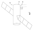
- FIG. 7 another aspect of the invention relates to a spacecraft 62 comprising a space-borne platform 64 to carry the antenna system 30.
- a space-borne antenna system 30 may be used for communications or radar applications as will be appreciated by those skilled in the art.
- the antenna system 30 may also be used in air-borne or terrestrial applications as well.
- the method starts at Block 50 and may include aligning a subreflector with an antenna feed, at Block 52, in which the subreflector has a concave surface defining a vertex.
- the method may further include aligning a main reflector at Block 54, which has a concave surface, with the subreflector to define an offset antenna focal point at the vertex of the subreflector.
- the method ends at Block 56 .
Abstract
Description
- The invention relates to the field of antennas, and, more particularly, to offset reflector antennas and related methods.
- An antenna is used to capture electromagnetic energy when operating in a receive mode, and to radiate such energy when in a transmitting mode. Accordingly, an antenna is a typical part of a communication system that also includes a transmitter and receiver, for example. To increase the antenna aperture, one or more reflectors may be arranged adjacent an antenna feed. An array feed including multiple elements may be used with such a reflector system to provide multiple beams or electronic scan capability.
-
U.S. Patent No. 6,236,375 to Chandler et al. discloses a reflector antenna including a feed array, a subreflector, and a main reflector, which are oriented to define an offset Gregorian antenna geometry. The antenna feed includes a plurality of separate feeds that are aligned on a predetermined contour and connected to a feed network to produce a plurality of composite illumination beams. The subreflector and main reflector are positioned so that the focal point of the main reflector is approximately coincident with the focal point associated with the convex side of the subreflector. The feed is positioned in proximity of the focal point associated with the concave side of the subreflector. -
U.S. Patent No. 4,203,105 to Dragone et al. discloses a feed array aligned with a confocal reflector system that includes a subreflector aligned with a main reflector at a coincident focal point.U.S. Patent Application Publication No. 2004/0008148 to Lyerly et al. also discloses a Gregorian antenna reflector system including a feed array, a subreflector, a main reflector, and at least one other subreflector. -
U.S. Patent No. 6,424,310 to Broas et al. discloses a feed array, a subreflector, and a main reflector, which are oriented to define a dual offset Cassegrain antenna geometry. The coincidental focal points of the main reflector and the subreflector are located on the convex side of the subreflector. -
U.S. Patent No. 6,215,452 to Chandler et al. discloses a feed array, a subreflector, and a main reflector, which are oriented to define a front-fed dual reflector antenna geometry. The coincident focal points of the main reflector and the subreflector are located on the concave side of the subreflector. -
U.S. Patent No. 6,211,835 to Peebles et al. discloses a feed array, a subreflector, and a main reflector, which are oriented to define a side-fed dual reflector antenna geometry. The coincidental focal points of the main reflector and the subreflector are located on the convex side of the subreflector. - A prior
art antenna system 20 is now described with reference to FIG. 1. Thisantenna system 20 includes afeed array 22 that illuminates asubreflector 23 that, in turn, reflects the energy to amain reflector 21. Thesubflector 23 is aligned with themain reflector 21 at a coincidentfocal point 24 in what is termed a near field Gregorian configuration. Unfortunately, such asystem 20 may be mechanically complex due to the relatively large displacement required between themain reflector 21 and thesubreflector 23. - There are two fundamental approaches for an array fed multiple beam or electronically scanned antenna system. The first is the Gregorian configuration as disclosed in
U.S. Patent Nos. 6,236,375 and4,203,105 . The second is a focused system like the Cassegrain systems ofU.S. Patent Nos. 6,424,310 ;6,215,452 ; and6,211,835 . - The focused system uses a focused antenna where the reflector(s) serves to focus the energy incident on the main reflector at a single point. Most reflector antennas are focused systems that use a single feed aligned to the focal point of the reflector or reflector system. When an array feed is used with a focused reflector system, feed array elements that are not on the focal point produce beams that have significant phase error, since they are not focused, resulting in distorted beam shapes and reduced beam gain. Multiple elements can be combined to overcome some of these effects, but the fundamental effect of pattern degradation as the beams are steered away from broadside is still present.
- Another technique is to use a very long focal length to reduce the defocusing effects with scan. In this technique, the feed element displacement from the focal point required to scan the beam is proportional to the focal length. As a result, for a given beam displacement range the feeds have to increase in size and number of elements as the focal length grows. Another fundamental aspect of a focused system is that the beams are scanned primarily by using different feed elements so that any particular beam may only use a small fraction of the feed. Consequently, such a focused system has a low feed utilization.
- The Gregorian or confocal (focal point of main and subreflector are coincident) dual reflector arrangement is distinctly different from the focused reflector systems. The optics of a Gregorian system concentrate the energy incident on the main reflector to a smaller aperture rather than a focal point. This property is sometimes referred to as aperture magnification since a scaled replica of the fields incident on the main reflector are produced at the feed. As a result, the Gregorian system may overcome many of the shortcomings of a conventional focused system because there is reduced beam distortion and most of the feed is utilized.
- The drawback with a Gregorian system is the large and cumbersome geometries that are required. The magnification is proportional to the ratio of the focal lengths. Consequently, to use a small feed and produce a large aperture with minimal blockage, a relatively large subreflector with significant separation from the main reflector is required.
- In view of the foregoing background, it is therefore an object of the invention to provide an antenna system and related method that can produce multiple beams or electronically scanned beam(s) with low beam distortion and high feed utilization in a compact package.
- This and other objects, features, and advantages in accordance with the invention are provided by an antenna system wherein the subreflector is positioned adjacent the focal area of the main reflector. The antenna system includes an antenna feed, and a subreflector aligned with the antenna feed. The subreflector may have a concave surface defining a vertex. The main reflector may have a parabolic or concave surface aligned with the subreflector to define an antenna focal point or area at the vertex of the subreflector. Accordingly, the antenna system provides the aperture magnification properties of the array fed Gregorian reflector configuration, but is relatively compact. The antenna focal point or area may be center fed, offset center fed, or implemented in an offset configuration to reduce blockage.
- The antenna feed may comprise an array feed with a beam forming network configured to provide multiple beams. Alternately, the antenna feed may comprise a phased array antenna feed with adjustable phase at each feed element. The antenna system may further comprise a controller cooperating with the phased array antenna feed for beamsteering, such as to define and steer multiple beams. The controller may further cooperate with the phased array antenna feed to define and steer multiple beams at different frequencies.
- The concave surfaces of the main reflector and subreflector may each have a parabolic shape in some embodiments. In other embodiments, the concave surfaces of the main reflector and subreflector may be flat in one dimension or have a partial cylindrical shape.
- The antenna system in accordance with the invention may have particular applicability to space-borne communications. Accordingly, another aspect of the invention is directed to a spacecraft comprising a space-borne platform to carry the antenna system.
- A method aspect of the invention is directed to making the antenna system. The method may include aligning a subreflector with an antenna feed in which the subreflector has a concave surface defining a vertex. The method may further include aligning a main reflector, which has a concave surface, with the subreflector to define a focal point at the vertex of the subreflector.
-
- FIG. 1 is a schematic diagram of a prior art near field Gregorian antenna configuration.
- FIG. 2 is a schematic diagram of a first embodiment of the antenna system according to the invention.
- FIG. 3 is a more detailed schematic diagram of the antenna feed shown in FIG. 2.
- FIG. 4 is an example of composite steered patterns produced by the antenna system of FIG. 2.
- FIG. 5 is a schematic diagram of a second embodiment of the antenna system according to the invention.
- FIG. 6 is schematic diagram of a third embodiment of the antenna system according to the invention.
- FIG. 7 is a schematic of a spacecraft including the antenna system shown in FIG. 2.
- FIG. 8 is a flowchart illustrating a method according to the invention.
- The invention will now be described more fully hereinafter with reference to the accompanying drawings, in which preferred embodiments of the invention are shown. This invention may, however, be embodied in many different forms and should not be construed as limited to the embodiments set forth herein. Rather, these embodiments are provided so that this disclosure will be thorough and complete, and will fully convey the scope of the invention to those skilled in the art. Like numbers refer to like elements throughout, and prime and multiple prime notation are used to indicate similar elements in alternate embodiments.
- The
antenna system 30 according to the invention is now described with reference to FIGS. 2 and 3. Theantenna system 30 includes anantenna feed 32. Asubreflector 33 is aligned with theantenna feed 32 and has aconcave surface 35 defining avertex 34. Amain reflector 31 having aconcave surface 36 is aligned with thesubreflector 33 to define an offset antenna focal area adjacent thevertex 34 of thesubreflector 33 as shown byrays 38. Accordingly, theantenna system 30 is relatively compact in comparison to the conventional near fieldGregorian antenna configuration 20 as shown in FIG. 1 and described above. - The
antenna system 30 has characteristics similar to theGregorian antenna configuration 20 by providing reduced distortion, aperture magnification, and full feed utilization. Theantenna system 30 achieves this is in a more compact geometry by manipulating the optics associated with thesubreflector 33. Thevertex 34 of thesubreflector 33 is placed at themain reflector 31 focal point instead of having coincident focal points, and the array feed phase distribution is manipulated to produce a feed/subreflector combination equivalent to theGregorian antenna configuration 20 in performance. Theantenna system 30 physically differs from theGregorian antenna configuration 20 by having a non-confocal configuration. For example, a smaller displacement between themain reflector 31 and thesubreflector 33, and by using asmaller subflector 33 than an equivalentGregorian antenna configuration 20. - The
antenna feed 32 may comprise a phased array antenna feed, for example, as schematically shown in FIG. 2. Theantenna system 30 also illustratively comprises acontroller 42 cooperating with the phasedarray antenna feed 32 for beamsteering. Thecontroller 42 may includemulti-beam circuitry 48 cooperating with the phased array antenna feed 32 to define and steer multiple beams. Thecontroller 42 may further includemulti-frequency circuitry 49 also cooperating with the phased array antenna feed 32 to define and steer multiple beams at different frequencies. Of course, in other embodiments, an antenna feed other than a phased array antenna feed may be used as will be appreciated by those skilled in the art. For instance, theantenna feed 32 may be in the form of a fixed array and beamformer that provides multiple beams. - An example of composite steered patterns is shown in FIG. 4. Composite steered patterns are formed by adjustment of the phase excitation at individual elements and combining the element outputs. The amplitude excitation is held constant across all elements. Three patterns are illustratively shown at 0 degrees, and plus/minus 6 degrees.
- The
concave surface 35 of thesubreflector 33 may have a parabolic shape in some embodiments, that is, a three-dimensional concave shape. For these embodiments, theconcave surface 36 of themain reflector 31 may also have a parabolic shape. In these embodiments, the focal area is a focal point and the vertex is a vertex point as will be appreciated by those skilled in the art. - In other embodiments, for example a two-dimensional configuration, the
concave surface 35 of thesubreflector 33 may be flat in one dimension or have a partial cylindrical shape and theconcave surface 36 of themain reflector 31 may have a partial cylindrical shape. - The antenna system may also be realized in
alternate configurations 30' and 30" as illustrated in FIGS. 5 and 6, respectively. The antenna system 30' of FIG. 5 is a center fed configuration, and theantenna system 30" of FIG. 6 is an offset center fed configuration. Those other elements not specifically described are indicated by prime and double prime notation, and require no further discussion herein. - Referring now additionally to FIG. 7, another aspect of the invention relates to a
spacecraft 62 comprising a space-borneplatform 64 to carry theantenna system 30. Such a space-borneantenna system 30 may be used for communications or radar applications as will be appreciated by those skilled in the art. Of course, theantenna system 30 may also be used in air-borne or terrestrial applications as well. - A method aspect of the invention for making the
antenna system 30 as now explained with reference to the flow chart 51 shown in FIG. 8. The method starts atBlock 50 and may include aligning a subreflector with an antenna feed, atBlock 52, in which the subreflector has a concave surface defining a vertex. The method may further include aligning a main reflector atBlock 54, which has a concave surface, with the subreflector to define an offset antenna focal point at the vertex of the subreflector. The method ends atBlock 56.
Claims (10)
- An antenna system comprising:an antenna feed;a subreflector aligned with said antenna feed and having a concave surface defining a vertex; anda main reflector having a concave surface and aligned with said subreflector to define an antenna focal area at the vertex of said subreflector.
- The antenna system according to Claim 1 wherein said antenna feed comprises an array antenna feed.
- The antenna system according to Claim 2 wherein said array antenna feed is in the form of a phased array; and further comprising a controller cooperating with said phased array antenna feed for beamsteering.
- The antenna system according to Claim 3 wherein said controller further cooperates with said phased array antenna feed to define and steer multiple beams.
- The antenna system according to Claim 2 wherein said array antenna feed is in the form of a fixed array; and further comprising a controller cooperating with said fixed array antenna feed for beamforming.
- The antenna system according to Claim 1 wherein said main reflector and subreflector are aligned to define an offset antenna focal area.
- The antenna system according to Claim 1 wherein said main reflector and subreflector are aligned to define at least one of a center fed antenna focal area and an offset center fed antenna focal area.
- A method for making an antenna system comprising:aligning a subreflector with an antenna feed, the subreflector having a concave surface defining a vertex; andaligning a main reflector having a concave surface and with the subreflector to define an antenna focal area at the vertex of the subreflector.
- The method according to Claim 8 further comprising beamsteering using a controller cooperating with the phased array antenna feed.
- The method according to Claim 9 further comprising using the controller in cooperation with the phased array antenna feed to define and steer multiple beams.
Applications Claiming Priority (1)
| Application Number | Priority Date | Filing Date | Title |
|---|---|---|---|
| US11/140,836 US7205949B2 (en) | 2005-05-31 | 2005-05-31 | Dual reflector antenna and associated methods |
Publications (2)
| Publication Number | Publication Date |
|---|---|
| EP1729368A1 true EP1729368A1 (en) | 2006-12-06 |
| EP1729368B1 EP1729368B1 (en) | 2008-10-01 |
Family
ID=36655117
Family Applications (1)
| Application Number | Title | Priority Date | Filing Date |
|---|---|---|---|
| EP06010994A Expired - Fee Related EP1729368B1 (en) | 2005-05-31 | 2006-05-29 | Dual reflector antenna and associated methods |
Country Status (3)
| Country | Link |
|---|---|
| US (1) | US7205949B2 (en) |
| EP (1) | EP1729368B1 (en) |
| DE (1) | DE602006002922D1 (en) |
Cited By (1)
| Publication number | Priority date | Publication date | Assignee | Title |
|---|---|---|---|---|
| WO2011056256A1 (en) * | 2009-11-06 | 2011-05-12 | Viasat, Inc. | Automated beam peaking satellite ground terminal |
Families Citing this family (30)
| Publication number | Priority date | Publication date | Assignee | Title |
|---|---|---|---|---|
| DE102008011350A1 (en) * | 2008-02-27 | 2009-09-03 | Loeffler Technology Gmbh | Apparatus and method for real-time detection of electromagnetic THz radiation |
| US8195118B2 (en) | 2008-07-15 | 2012-06-05 | Linear Signal, Inc. | Apparatus, system, and method for integrated phase shifting and amplitude control of phased array signals |
| US8872719B2 (en) | 2009-11-09 | 2014-10-28 | Linear Signal, Inc. | Apparatus, system, and method for integrated modular phased array tile configuration |
| CN102891372B (en) * | 2011-05-11 | 2014-11-05 | 深圳光启高等理工研究院 | Scattering type metamaterial directional antenna |
| CN102790277B (en) * | 2011-05-17 | 2015-04-15 | 深圳光启创新技术有限公司 | Directional antenna |
| CN102790288B (en) * | 2011-05-18 | 2015-03-11 | 深圳光启创新技术有限公司 | Directional antenna |
| CN102427169B (en) * | 2011-08-30 | 2014-11-26 | 四川大学 | Microwave combined beam launcher |
| FR3015787B1 (en) * | 2013-12-23 | 2017-06-09 | Thales Sa | METHOD FOR DEFINING THE STRUCTURE OF A KA BAND ANTENNA |
| US10122085B2 (en) * | 2014-12-15 | 2018-11-06 | The Boeing Company | Feed re-pointing technique for multiple shaped beams reflector antennas |
| RU2623652C1 (en) * | 2016-10-01 | 2017-06-28 | Евгений Петрович Баснев | Multi-wave antenna (versions) |
| RU2642512C1 (en) * | 2016-10-01 | 2018-01-25 | Евгений Петрович Баснев | Multi-beam antenna |
| US10333217B1 (en) | 2018-01-12 | 2019-06-25 | Pivotal Commware, Inc. | Composite beam forming with multiple instances of holographic metasurface antennas |
| US10225760B1 (en) | 2018-03-19 | 2019-03-05 | Pivotal Commware, Inc. | Employing correlation measurements to remotely evaluate beam forming antennas |
| US10425905B1 (en) * | 2018-03-19 | 2019-09-24 | Pivotal Commware, Inc. | Communication of wireless signals through physical barriers |
| CN108649345B (en) * | 2018-04-12 | 2020-08-28 | 中国科学院电子学研究所 | Confocal double-paraboloid antenna |
| US10862545B2 (en) | 2018-07-30 | 2020-12-08 | Pivotal Commware, Inc. | Distributed antenna networks for wireless communication by wireless devices |
| US10326203B1 (en) * | 2018-09-19 | 2019-06-18 | Pivotal Commware, Inc. | Surface scattering antenna systems with reflector or lens |
| US10522897B1 (en) | 2019-02-05 | 2019-12-31 | Pivotal Commware, Inc. | Thermal compensation for a holographic beam forming antenna |
| US10468767B1 (en) * | 2019-02-20 | 2019-11-05 | Pivotal Commware, Inc. | Switchable patch antenna |
| US10734736B1 (en) | 2020-01-03 | 2020-08-04 | Pivotal Commware, Inc. | Dual polarization patch antenna system |
| US11069975B1 (en) | 2020-04-13 | 2021-07-20 | Pivotal Commware, Inc. | Aimable beam antenna system |
| KR20230017280A (en) | 2020-05-27 | 2023-02-03 | 피보탈 컴웨어 인코포레이티드 | RF signal repeater device management for 5G wireless networks |
| US11026055B1 (en) | 2020-08-03 | 2021-06-01 | Pivotal Commware, Inc. | Wireless communication network management for user devices based on real time mapping |
| WO2022056024A1 (en) | 2020-09-08 | 2022-03-17 | Pivotal Commware, Inc. | Installation and activation of rf communication devices for wireless networks |
| CN112151970A (en) * | 2020-09-25 | 2020-12-29 | 重庆两江卫星移动通信有限公司 | Cassegrain antenna with scanning function |
| US11843955B2 (en) | 2021-01-15 | 2023-12-12 | Pivotal Commware, Inc. | Installation of repeaters for a millimeter wave communications network |
| JP2024505881A (en) | 2021-01-26 | 2024-02-08 | ピヴォタル コムウェア インコーポレイテッド | smart repeater system |
| US11451287B1 (en) | 2021-03-16 | 2022-09-20 | Pivotal Commware, Inc. | Multipath filtering for wireless RF signals |
| CA3224854A1 (en) | 2021-07-07 | 2023-01-12 | Pivotal Commware, Inc. | Multipath repeater systems |
| US11937199B2 (en) | 2022-04-18 | 2024-03-19 | Pivotal Commware, Inc. | Time-division-duplex repeaters with global navigation satellite system timing recovery |
Citations (9)
| Publication number | Priority date | Publication date | Assignee | Title |
|---|---|---|---|---|
| US4203105A (en) | 1978-05-17 | 1980-05-13 | Bell Telephone Laboratories, Incorporated | Scanable antenna arrangements capable of producing a large image of a small array with minimal aberrations |
| US4479129A (en) * | 1981-09-10 | 1984-10-23 | George Skahill | Directive antenna system employing a paraboloidal main dish and ellipsoidal subdish |
| US4755826A (en) * | 1983-01-10 | 1988-07-05 | The United States Of America As Represented By The Secretary Of The Navy | Bicollimated offset Gregorian dual reflector antenna system |
| JPH1065438A (en) * | 1996-06-10 | 1998-03-06 | Hisamatsu Nakano | Double reflector type small aperture parabolic antenna system |
| US6211835B1 (en) | 1999-01-15 | 2001-04-03 | Trw Inc. | Compact side-fed dual reflector antenna system for providing adjacent, high gain antenna beams |
| US6215452B1 (en) | 1999-01-15 | 2001-04-10 | Trw Inc. | Compact front-fed dual reflector antenna system for providing adjacent, high gain antenna beams |
| US6236375B1 (en) | 1999-01-15 | 2001-05-22 | Trw Inc. | Compact offset gregorian antenna system for providing adjacent, high gain, antenna beams |
| US6424310B1 (en) | 1999-01-15 | 2002-07-23 | Trw Inc. | Compact folded optics antenna system for providing adjacent, high gain antenna beams |
| US20040008148A1 (en) | 2002-07-10 | 2004-01-15 | Lyerly Albert E. | Gregorian antenna system for shaped beam and multiple frequency use |
Family Cites Families (14)
| Publication number | Priority date | Publication date | Assignee | Title |
|---|---|---|---|---|
| US3953858A (en) * | 1975-05-30 | 1976-04-27 | Bell Telephone Laboratories, Incorporated | Multiple beam microwave apparatus |
| US4298877A (en) * | 1979-01-26 | 1981-11-03 | Solar Energy Technology, Inc. | Offset-fed multi-beam tracking antenna system utilizing especially shaped reflector surfaces |
| US4364052A (en) * | 1980-10-29 | 1982-12-14 | Bell Telephone Laboratories, Incorporated | Antenna arrangements for suppressing selected sidelobes |
| US4355314A (en) * | 1980-11-28 | 1982-10-19 | Bell Telephone Laboratories, Incorporated | Wide-field-of-view antenna arrangement |
| US4535338A (en) * | 1982-05-10 | 1985-08-13 | At&T Bell Laboratories | Multibeam antenna arrangement |
| JPS59143405A (en) * | 1983-02-04 | 1984-08-17 | Kokusai Denshin Denwa Co Ltd <Kdd> | Multibeam antenna |
| US4618867A (en) * | 1984-06-14 | 1986-10-21 | At&T Bell Laboratories | Scanning beam antenna with linear array feed |
| US5790077A (en) * | 1996-10-17 | 1998-08-04 | Space Systems/Loral, Inc. | Antenna geometry for shaped dual reflector antenna |
| US5859619A (en) * | 1996-10-22 | 1999-01-12 | Trw Inc. | Small volume dual offset reflector antenna |
| US6150991A (en) * | 1998-11-12 | 2000-11-21 | Raytheon Company | Electronically scanned cassegrain antenna with full aperture secondary/radome |
| FR2802381B1 (en) * | 1999-12-09 | 2002-05-31 | Cit Alcatel | RADIANT SOURCE FOR TRANSMISSION AND RECEPTION ANTENNA FOR MOUNTING ON BOARD A SATELLITE |
| US6198455B1 (en) * | 2000-03-21 | 2001-03-06 | Space Systems/Loral, Inc. | Variable beamwidth antenna systems |
| US6342865B1 (en) * | 2000-11-29 | 2002-01-29 | Trw Inc. | Side-fed offset cassegrain antenna with main reflector gimbal |
| US6580399B1 (en) * | 2002-01-11 | 2003-06-17 | Northrop Grumman Corporation | Antenna system having positioning mechanism for reflector |
-
2005
- 2005-05-31 US US11/140,836 patent/US7205949B2/en active Active
-
2006
- 2006-05-29 DE DE602006002922T patent/DE602006002922D1/en active Active
- 2006-05-29 EP EP06010994A patent/EP1729368B1/en not_active Expired - Fee Related
Patent Citations (9)
| Publication number | Priority date | Publication date | Assignee | Title |
|---|---|---|---|---|
| US4203105A (en) | 1978-05-17 | 1980-05-13 | Bell Telephone Laboratories, Incorporated | Scanable antenna arrangements capable of producing a large image of a small array with minimal aberrations |
| US4479129A (en) * | 1981-09-10 | 1984-10-23 | George Skahill | Directive antenna system employing a paraboloidal main dish and ellipsoidal subdish |
| US4755826A (en) * | 1983-01-10 | 1988-07-05 | The United States Of America As Represented By The Secretary Of The Navy | Bicollimated offset Gregorian dual reflector antenna system |
| JPH1065438A (en) * | 1996-06-10 | 1998-03-06 | Hisamatsu Nakano | Double reflector type small aperture parabolic antenna system |
| US6211835B1 (en) | 1999-01-15 | 2001-04-03 | Trw Inc. | Compact side-fed dual reflector antenna system for providing adjacent, high gain antenna beams |
| US6215452B1 (en) | 1999-01-15 | 2001-04-10 | Trw Inc. | Compact front-fed dual reflector antenna system for providing adjacent, high gain antenna beams |
| US6236375B1 (en) | 1999-01-15 | 2001-05-22 | Trw Inc. | Compact offset gregorian antenna system for providing adjacent, high gain, antenna beams |
| US6424310B1 (en) | 1999-01-15 | 2002-07-23 | Trw Inc. | Compact folded optics antenna system for providing adjacent, high gain antenna beams |
| US20040008148A1 (en) | 2002-07-10 | 2004-01-15 | Lyerly Albert E. | Gregorian antenna system for shaped beam and multiple frequency use |
Non-Patent Citations (1)
| Title |
|---|
| PATENT ABSTRACTS OF JAPAN vol. 1998, no. 08 30 June 1998 (1998-06-30) * |
Cited By (1)
| Publication number | Priority date | Publication date | Assignee | Title |
|---|---|---|---|---|
| WO2011056256A1 (en) * | 2009-11-06 | 2011-05-12 | Viasat, Inc. | Automated beam peaking satellite ground terminal |
Also Published As
| Publication number | Publication date |
|---|---|
| DE602006002922D1 (en) | 2008-11-13 |
| US20060267851A1 (en) | 2006-11-30 |
| EP1729368B1 (en) | 2008-10-01 |
| US7205949B2 (en) | 2007-04-17 |
Similar Documents
| Publication | Publication Date | Title |
|---|---|---|
| EP1729368B1 (en) | Dual reflector antenna and associated methods | |
| US4618867A (en) | Scanning beam antenna with linear array feed | |
| US6198455B1 (en) | Variable beamwidth antenna systems | |
| KR100944216B1 (en) | Compact multi beam reflector antenna | |
| EP0028018B1 (en) | An improved phased array antenna system | |
| US6236375B1 (en) | Compact offset gregorian antenna system for providing adjacent, high gain, antenna beams | |
| CN109841961B (en) | Multi-beam double-mirror antenna based on super surface | |
| KR101292230B1 (en) | Compact nonaxisymmetric double-reflector antenna | |
| EP3114730A1 (en) | Imaging antenna systems with compensated optical aberrations based on unshaped surface reflectors | |
| US5598173A (en) | Shaped-beam or scanned beams reflector or lens antenna | |
| EP3200279B1 (en) | Multifocal phased array fed reflector antenna | |
| JP2015505229A (en) | Two-dimensional multi-beamformer, antenna comprising such a multi-beamformer and satellite communication system comprising such an antenna | |
| US4250508A (en) | Scanning beam antenna arrangement | |
| US6411255B2 (en) | Reflector antenna comprising a plurality of panels | |
| US6215452B1 (en) | Compact front-fed dual reflector antenna system for providing adjacent, high gain antenna beams | |
| WO1987003746A1 (en) | High efficiency optical limited scan antenna | |
| US6690333B2 (en) | Cylindrical ray imaging steered beam array (CRISBA) antenna | |
| US4439773A (en) | Compact scanning beam antenna feed arrangement | |
| JP2022539676A (en) | Imaging reflector antenna system | |
| CA2293506C (en) | A compact folded optics antenna system for providing adjacent, high gain antenna beams | |
| WO2019170541A1 (en) | Extreme scanning focal-plane arrays using a double-reflector concept with uniform array illumination | |
| EP1207584B1 (en) | Integrated dual beam reflector antenna | |
| EP1059689A2 (en) | Dual gridded reflector antenna system | |
| GB2262387A (en) | Multibeam antenna | |
| JPS6119528Y2 (en) |
Legal Events
| Date | Code | Title | Description |
|---|---|---|---|
| PUAI | Public reference made under article 153(3) epc to a published international application that has entered the european phase |
Free format text: ORIGINAL CODE: 0009012 |
|
| 17P | Request for examination filed |
Effective date: 20060529 |
|
| AK | Designated contracting states |
Kind code of ref document: A1 Designated state(s): AT BE BG CH CY CZ DE DK EE ES FI FR GB GR HU IE IS IT LI LT LU LV MC NL PL PT RO SE SI SK TR |
|
| AX | Request for extension of the european patent |
Extension state: AL BA HR MK YU |
|
| AKX | Designation fees paid |
Designated state(s): DE FR GB |
|
| 17Q | First examination report despatched |
Effective date: 20070810 |
|
| GRAP | Despatch of communication of intention to grant a patent |
Free format text: ORIGINAL CODE: EPIDOSNIGR1 |
|
| GRAS | Grant fee paid |
Free format text: ORIGINAL CODE: EPIDOSNIGR3 |
|
| GRAA | (expected) grant |
Free format text: ORIGINAL CODE: 0009210 |
|
| RAP1 | Party data changed (applicant data changed or rights of an application transferred) |
Owner name: HARRIS CORPORATION |
|
| AK | Designated contracting states |
Kind code of ref document: B1 Designated state(s): DE FR GB |
|
| REG | Reference to a national code |
Ref country code: GB Ref legal event code: FG4D |
|
| REF | Corresponds to: |
Ref document number: 602006002922 Country of ref document: DE Date of ref document: 20081113 Kind code of ref document: P |
|
| PLBE | No opposition filed within time limit |
Free format text: ORIGINAL CODE: 0009261 |
|
| STAA | Information on the status of an ep patent application or granted ep patent |
Free format text: STATUS: NO OPPOSITION FILED WITHIN TIME LIMIT |
|
| 26N | No opposition filed |
Effective date: 20090702 |
|
| REG | Reference to a national code |
Ref country code: FR Ref legal event code: PLFP Year of fee payment: 10 |
|
| PGFP | Annual fee paid to national office [announced via postgrant information from national office to epo] |
Ref country code: GB Payment date: 20150527 Year of fee payment: 10 Ref country code: DE Payment date: 20150528 Year of fee payment: 10 |
|
| PGFP | Annual fee paid to national office [announced via postgrant information from national office to epo] |
Ref country code: FR Payment date: 20150519 Year of fee payment: 10 |
|
| REG | Reference to a national code |
Ref country code: DE Ref legal event code: R119 Ref document number: 602006002922 Country of ref document: DE |
|
| GBPC | Gb: european patent ceased through non-payment of renewal fee |
Effective date: 20160529 |
|
| REG | Reference to a national code |
Ref country code: FR Ref legal event code: ST Effective date: 20170131 |
|
| PG25 | Lapsed in a contracting state [announced via postgrant information from national office to epo] |
Ref country code: DE Free format text: LAPSE BECAUSE OF NON-PAYMENT OF DUE FEES Effective date: 20161201 Ref country code: FR Free format text: LAPSE BECAUSE OF NON-PAYMENT OF DUE FEES Effective date: 20160531 |
|
| PG25 | Lapsed in a contracting state [announced via postgrant information from national office to epo] |
Ref country code: GB Free format text: LAPSE BECAUSE OF NON-PAYMENT OF DUE FEES Effective date: 20160529 |