EP1729351A1 - Ultrasonic Motor Device - Google Patents
Ultrasonic Motor Device Download PDFInfo
- Publication number
- EP1729351A1 EP1729351A1 EP06114579A EP06114579A EP1729351A1 EP 1729351 A1 EP1729351 A1 EP 1729351A1 EP 06114579 A EP06114579 A EP 06114579A EP 06114579 A EP06114579 A EP 06114579A EP 1729351 A1 EP1729351 A1 EP 1729351A1
- Authority
- EP
- European Patent Office
- Prior art keywords
- ultrasonic motor
- driving
- driving signal
- control
- movement
- Prior art date
- Legal status (The legal status is an assumption and is not a legal conclusion. Google has not performed a legal analysis and makes no representation as to the accuracy of the status listed.)
- Granted
Links
- 238000001514 detection method Methods 0.000 claims abstract description 11
- 230000005540 biological transmission Effects 0.000 claims description 11
- 230000001133 acceleration Effects 0.000 claims description 8
- 238000000034 method Methods 0.000 claims description 8
- 230000003287 optical effect Effects 0.000 claims description 3
- 238000010586 diagram Methods 0.000 description 12
- 101100236764 Caenorhabditis elegans mcu-1 gene Proteins 0.000 description 11
- 230000004044 response Effects 0.000 description 8
- 230000000694 effects Effects 0.000 description 6
- 230000009471 action Effects 0.000 description 5
- 230000007246 mechanism Effects 0.000 description 4
- 230000002411 adverse Effects 0.000 description 2
- 230000005856 abnormality Effects 0.000 description 1
- 230000007613 environmental effect Effects 0.000 description 1
- 238000012986 modification Methods 0.000 description 1
- 230000004048 modification Effects 0.000 description 1
- 230000002093 peripheral effect Effects 0.000 description 1
- 230000011514 reflex Effects 0.000 description 1
- 230000035807 sensation Effects 0.000 description 1
- 230000007704 transition Effects 0.000 description 1
Images


Classifications
-
- G—PHYSICS
- G02—OPTICS
- G02B—OPTICAL ELEMENTS, SYSTEMS OR APPARATUS
- G02B7/00—Mountings, adjusting means, or light-tight connections, for optical elements
- G02B7/02—Mountings, adjusting means, or light-tight connections, for optical elements for lenses
- G02B7/04—Mountings, adjusting means, or light-tight connections, for optical elements for lenses with mechanism for focusing or varying magnification
- G02B7/08—Mountings, adjusting means, or light-tight connections, for optical elements for lenses with mechanism for focusing or varying magnification adapted to co-operate with a remote control mechanism
-
- H—ELECTRICITY
- H02—GENERATION; CONVERSION OR DISTRIBUTION OF ELECTRIC POWER
- H02N—ELECTRIC MACHINES NOT OTHERWISE PROVIDED FOR
- H02N2/00—Electric machines in general using piezoelectric effect, electrostriction or magnetostriction
- H02N2/10—Electric machines in general using piezoelectric effect, electrostriction or magnetostriction producing rotary motion, e.g. rotary motors
- H02N2/12—Constructional details
- H02N2/123—Mechanical transmission means, e.g. for gearing
-
- H—ELECTRICITY
- H02—GENERATION; CONVERSION OR DISTRIBUTION OF ELECTRIC POWER
- H02N—ELECTRIC MACHINES NOT OTHERWISE PROVIDED FOR
- H02N2/00—Electric machines in general using piezoelectric effect, electrostriction or magnetostriction
- H02N2/10—Electric machines in general using piezoelectric effect, electrostriction or magnetostriction producing rotary motion, e.g. rotary motors
- H02N2/14—Drive circuits; Control arrangements or methods
- H02N2/142—Small signal circuits; Means for controlling position or derived quantities, e.g. speed, torque, starting, stopping, reversing
Definitions
- the present invention relates to an ultrasonic motor device for controlling driving of an ultrasonic motor.
- an ultrasonic motor device comprises: an ultrasonic motor that moves an object; a detecting means that detects movement of the object; and a control means that drives the ultrasonic motor according to a first driving signal before detection of the movement of the object, and drives the ultrasonic motor according to a second driving signal, which is different from the first driving signal, after detection of the movement of the object.
- the ultrasonic motor device in the ultrasonic motor device according to the 1st aspect, it is preferred that: there is further provided a transmission means that transmits driving force of the ultrasonic motor to the object; and the control means controls transmission error in the transmission means by driving the ultrasonic motor according to the first driving signal.
- the transmission means includes a gear train.
- control means sets the first driving signal and the second driving signal such that a driving speed of the ultrasonic motor driven according to the second driving signal is faster than a driving speed of the ultrasonic motor driven according to the first driving signal.
- the control means detects a movement speed of the object which is the same as a movement speed of the obj ect driven according to the first driving signal, during at least one of a time of acceleration and a time of deceleration when the ultrasonic motor is driven according to the second driving signal.
- control means drives the ultrasonic motor according to the second driving signal, following driving the ultrasonic motor according to the first driving signal for a predetermined amount of time.
- the detecting means comprises an encoder.
- the first driving signal is a signal used for driving the ultrasonic motor under open loop control
- the second driving signal is a signal used for driving the ultrasonic motor under feedback control
- control means performs feedback control according to the second driving signal, based on information from the detecting means.
- a lens barrel comprises: a main lens barrel having an optical component; and an ultrasonic motor device according to any one of the 1st through 9th aspects.
- a camera is capable of mounting a lens barrel according to the 10th aspect.
- a control method for controlling an ultrasonic motor device comprises: driving of an ultrasonic motor according to a first driving signal; detecting of movement of an object moved by the ultrasonic motor; and driving of the ultrasonic motor according to a second driving signal which differs from the first driving signal, following detection of the movement of the object.
- control mode is switched to a mode in which the ultrasonic motor is driven according to the second driving signal.
- a movement speed of the object which is the same as a movement speed of the object driven according to the first driving signal is detected during at least one of a time of acceleration and a time of deceleration when the ultrasonic motor is driven according to the second driving signal.
- the first driving signal is a signal used for driving the ultrasonic motor under open loop control
- the second driving signal is a signal used for driving the ultrasonic motor under feedback control
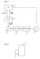
- Fig. 1 is a configuration diagram of an ultrasonic motor device (control device) which is an embodiment of the present invention
- Fig. 2 is a diagram illustrating a lens barrel 11 and a camera body 12 with which the ultrasonic motor device is used.
- the ultrasonic motor device according to the present embodiment is mounted within a lens barrel 11, and is used for driving lenses (optical components) for automatic focus control and so forth.
- the power supply for the ultrasonic motor device is supplied from the camera body 12.
- an MCU 1 is provided, which is configured from a microcomputer and peripheral circuits thereof, for executing predetermined programs and performing driving control of the ultrasonic motor 3 based on external instructions.
- the MCU 1 also receives signals from an encoder 4, and outputs DA (digital-to-analog) output corresponding to the driving frequency, and On/Off signals for permitting/forbidding driving operations, according to the external instructions and the signals from the encoder 4.
- DA digital-to-analog
- a driver 2 receives the On/Off signals and the DA output from the MCU 1, and outputs driving signals to the ultrasonic motor 3.
- An unshown VCO Voltage Control Oscillator
- the ultrasonic motor 3 rotates at the rotation speed corresponding to the driving frequency of the input driving signals, and transmits driving force to a control object 5 via a gear train (transmission mechanism) 6.
- a gear train transmission mechanism
- the relation between driving frequency and the rotation speed of the ultrasonic motor 3 exhibit generally inversely proportionate properties, so that increasing the driving frequency lowers the rotation speed of the ultrasonic motor 3.
- the encoder 4 is attached nearby the control object 5, so as to detect movement of the control object 5.
- Fig. 7A is a diagram illustrating the ultrasonic motor 3 and the gear train 6.
- the ultrasonic motor 3 is configured of a stator 31, rotor 32, and a rotor shaft 33, with the rotor 32 and the rotor shaft 33 rotating.
- a pinion gear 61 is attached to the rotor shaft 33. Rotational force of the ultrasonic motor 3 is transmitted to a segment gear 62 via the pinion gear 61, with the pinion gear 61 and segment gear 62 making up the gear train 6.
- the segment gear 62 is formed cylindrically, and engaged with a lens holding frame. Furthermore, the segment gear 62 also serves as the control object 5 shown in Fig. 1.
- An encoder 4 (not shown in Fig. 7A) is disposed near the segment gear 62, for detecting rotation of the segment gear 62. In the event of rotating the segment gear 62 in the counter-clockwise direction, the ultrasonic motor 3 is driven such that the rotor 32 is driven in the counter-clockwise direction, and in the event of rotating the segment gear 62 in the clockwise direction, the ultrasonic motor 3 is driven such that the rotor 32 is driven in the clockwise direction.
- Fig. 7B is a diagram depicting a state wherein there is backlash in the gear train 6 at the time of the pinion gear 61 rotating in the direction indicated by the arrow. Another way of describing backlash would be to say space between the engaging portions (teeth) of the pinion gear 61 and the segment gear 62.
- Fig. 7C is a diagram depicting a state wherein the backlash in the gear train 6 has been taken up or removed due to the pinion gear 61 having rotated in the direction indicated by the arrow. In the state wherein the backlash has disappeared, there is no space at the engaged portion between the pinion gear 61 and the segment gear 62, with the teeth of the pinion gear 61 and the segment gear 62 being in contact.
- driving signals are output by open loop control at a speed level such that the control object 5 will not be bumped away at the time of starting driving the ultrasonic motor 3 (i.e., the backlash removal speed), and upon detection that the backlash has been taken up, the mode is switched to feed back control which is normal control, so that driving signals generated based on feedback control are output.
- Open loop control means control which is not feed back control, or more simply control without feedback, and can also be referred to as "feed-forward control”.
- the ultrasonic motor 3 is capable of changing the rotation speed by changing the driving frequency, but the correlation between the frequency and the rotation speed is not stable, due to various factors such as ambient temperature, load torque, rotational irregularities, and so forth. Accordingly, even if open loop control is being performed at a speed level such that the control object 5 is not bumped away, environmental changes may result in higher-than-expected speeds bumping the control object away, or conversely insufficient speeds leading to longer driving time, and in worst-scenario cases movement may stop completely.
- the driving frequency (DA output) for backlash removal is always updated with the driving frequency (DA output) corresponding to the driving speed for backlash removal that has been obtained by the immediately-preceding driving.
- the next driving for backlash removal is performed using the driving frequency thus updated.
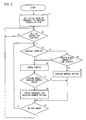
- Fig. 3 is a flowchart illustrating processing with the MCU 1. This processing starts by turning the power of the camera body 12 on.
- step S1 the backlash removal driving frequency (DA output) is set to an initial value in the initialization immediately following turning the power on.
- step S2 determination is made regarding whether or not there has been a driving instruction. In the event that there has been a driving instruction the flow proceeds to step S3. On the other hand, in the event that there has been no driving instruction, the processing in step S2 is repeated.
- step S3 determination is made regarding whether or not backlash has been taken up or removed. This is determined by determining whether or not the control object 5 has begun to move, based on signals from the encoder 4. In the event that the backlash has not been taken up yet, the flow proceeds to step S4. Otherwise, the flow proceeds to step S6. In the event that backlash has been taken up, control is effected such that another backlash removal is not performed in driving for one time.
- step S4 determination is made regarding whether or not a predetermined amount of time has elapsed. This is to provide a time limit for backlash removal. With such an arrangement, in the event that the backlash removal is not completed due to some sort of abnormality, transition is made to normal control.
- step S5 backlash removal is performed, wherein driving signals of the set backlash removal driving frequency (DA output value) are output until the backlash is taken up.
- step S6 feedback control is performed as the normal control processing.
- the MCU 1 obtains the speed of the control object 5 based on signals from the encoder 4, and performs feedback control of the ultrasonic motor 3 so as to match the target speed.
- the speed and the driving frequency (DA output value) at this time are stored in unshown memory, for use in the later-described step S8.
- the memory further has capacity for storing data for the duration of the later-described response delay time.
- step S7 determination is made regarding whether or not the speed of the control object 5 detected by the encoder 4 is equal to the backlash removal driving speed.
- This backlash removal driving speed is the driving speed at which the control object 5 is driven in a backlash-removed state in the event of driving the ultrasonic motor 3 at a backlash removal frequency (backlash removal signals). This can also be referred to as "backlash removal signal speed”.
- the speed of the control object 5 is determined by computation performed by the MCU 1, based on the signals from the encoder 4. In the event that the speed of the control object 5 is equal to the backlash removal driving speed, the flow proceeds to step S8. Otherwise, the flow proceeds to step S9.
- step S8 giving consideration to response delay, the driving frequency (DA output value) output in the past for the duration of the response delay time is written to the unshown memory as the new driving frequency (DA output value).
- the driving frequency (DA output value) output in the past for the duration of the response delay time is obtained from memory where it has been stored in step S6.
- step S9 in the event that conditions for ending driving are complete according to another unshown routine, the driving ends and the flow returns to step S2. Accordingly, driving for one time ends. An example wouldbe a case wherein auto-focusing of the lens barrel 11 is completed. Otherwise, the flow returns to step s3 for each control cycle.
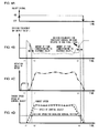
- Figs. 4A through 4D are diagrams illustrating the driving of the ultrasonic motor 3 for one time following turning the power of the camera body 12 on. This illustrates one time of driving, which is equivalent to step S1 through step S9 in the flowchart shown in Fig. 3.
- Fig. 4A illustrates the On/Off signal which the MCU 1 outputs.
- Fig. 4B illustrates the driving frequency (DA output value) of the ultrasonic motor 3 which the MCU 1 outputs.
- Fig. 4C illustrates the movement, i.e., the number of rotations (rotational speed) of the ultrasonic motor 3.
- Fig. 4D illustrates the driving speed of the control object 5, wherein the dotted liens show the target speed of the control object 5 while the solid lines show the actual driving speed (moving speed) of the control object 5 that is detected by the encoder 4.
- the MCU 1 sets the On/Off signal to on. Furthermore, the MCU 1 outputs a predetermined value of the driving frequency (DA output), which is used for backlash removal driving (see Figs. 4A and 4B). This action corresponds to proceeding from step S2 to step S3 in Fig. 3.
- the ultrasonic motor 3 starts moving following a delay time corresponding to the response delay (see Fig. 4C). Subsequently, control mode is switched to feedback control at the timing t1 at which there is output from the encoder 4 (see Fig. 4B). This action corresponds to proceeding from step S3 to step S6 in Fig. 3.
- the ultrasonic motor 3 accelerates at a constant rate under feedback control. Then, following attaining top speed, the speed is maintained. In the final stage, the speed is reduced at a constant rate.
- t2 and t3 at which the speed of the movement of the control object 5 matches the backlash removal driving speed.
- the driving speed under feedback control i.e., the top speed, is set so as to be faster than the backlash removal driving speed.
- step S8 the backlash removal driving frequency is updated.
- the frequencies (DA outputs) updated at these points in time i.e., the values indicated by the circles in Fig. 4B are employed as the past values by an amount corresponding to response delay. While this updating is performed twice in Fig. 4B, the final value is the newer value at t3.
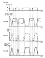
- Figs. 5A through 5D are drawings illustrating driving of the ultrasonic motor 3 multiple times. While driving is performed four times, each time following the first time uses the backlash removal driving frequency (DA output) obtained at the deceleration portion of the immediately-preceding driving for performing the backlash removal driving. Thus, while the backlash removal driving frequency (DA output) differs for each time, the motor rotation speed exhibits a backlash removal driving speed consistent with expectations. This action corresponds to repeating the proceeding from step S2 through step S9 in Fig. 3 four times.
- DA output backlash removal driving frequency
- Figs. 6A through 6D are graphs illustrating driving of the ultrasonic motor 3 in the event of not updating backlash removal driving frequency.
- the backlash removal driving frequency remains at the initial value and is not changed. Accordingly, the driving frequency at the backlash removal driving portions in Fig. 6B is exactly the same for all four driving times.
- the actual motor rotation speed at the third time are only half of the expected rotation speed (see Fig. 6C), so the backlash removal driving takes time.
- the actual motor rotation speed exceed the expected rotation speed (see Fig. 6C), so the control object is bumped away and the speed thereof is disturbed (see Fig. 6D). Note that in Fig. 6D, the solid lines show the actual speed of the control object 5, and the broken lines show the target speed.
- the ultrasonic motor device that is configured as described above has the following advantages.
- ultrasonic motor device can be applied to all usages in which ultrasonic motors are employed.
- the ultrasonic motor may be a rotational ultrasonic motor or a linear ultrasonic motor.
- ultrasonic motor as used here also includes what are known as vibration actuators.
- connection mechanism from the ultrasonic motor 3 to the gear train, and the connection mechanism from the gear train to the control object 5 also have backlash.
- the aforementioned backlash removal driving allows the adverse effects of such backlash to be removed. That is to say, the present invention is applied to remove the adverse effects of backlash existing throughout the entire mechanism for transmitting the driving force of the ultrasonic motor 3 to the control object 5.
Landscapes
- Physics & Mathematics (AREA)
- General Physics & Mathematics (AREA)
- Optics & Photonics (AREA)
- General Electrical Machinery Utilizing Piezoelectricity, Electrostriction Or Magnetostriction (AREA)
- Lens Barrels (AREA)
- Fittings On The Vehicle Exterior For Carrying Loads, And Devices For Holding Or Mounting Articles (AREA)
- Power Steering Mechanism (AREA)
- Surgical Instruments (AREA)
- Control Of Electric Motors In General (AREA)
Abstract
Description
- The present invention relates to an ultrasonic motor device for controlling driving of an ultrasonic motor.
- There is known a control device for controlling driving of an ultrasonic motor while feeding back output from a speed detector such as an encoder. (see
Japanese Laid-open Patent Publication No. 2003-304691 - However, in the event of driving the ultrasonic motor with backlash between gears, movement of the ultrasonic motor is not detected until the backlash has been taken up, even though the ultrasonic motor is actually moving. Accordingly, the feedback control results in acceleration, and moving too fast in turn bumps away the article to be controlled at the point that the backlash runs out, and then backlash is generated again. Such effects of backlash being repeated have been problematic in proper control.
- According to the 1st aspect of the invention, an ultrasonic motor device comprises: an ultrasonic motor that moves an object; a detecting means that detects movement of the object; and a control means that drives the ultrasonic motor according to a first driving signal before detection of the movement of the object, and drives the ultrasonic motor according to a second driving signal, which is different from the first driving signal, after detection of the movement of the object.
- According to the 2nd aspect of the invention, in the ultrasonic motor device according to the 1st aspect, it is preferred that: there is further provided a transmission means that transmits driving force of the ultrasonic motor to the object; and the control means controls transmission error in the transmission means by driving the ultrasonic motor according to the first driving signal.
- According to the 3rd aspect of the invention, in the ultrasonic motor device according to the 2nd aspect, it is preferred that the transmission means includes a gear train.
- According to the 4th aspect of the invention, in the ultrasonic motor device according to any one of the 1st through 3rd aspects, it is preferred that the control means sets the first driving signal and the second driving signal such that a driving speed of the ultrasonic motor driven according to the second driving signal is faster than a driving speed of the ultrasonic motor driven according to the first driving signal.
- According to the 5th aspect of the invention, in the ultrasonic motor device according to any one of the 1st through 4th aspects, it is preferred that the control means detects a movement speed of the object which is the same as a movement speed of the obj ect driven according to the first driving signal, during at least one of a time of acceleration and a time of deceleration when the ultrasonic motor is driven according to the second driving signal.
- According to the 6th aspect of the invention, in the ultrasonic motor device according to any one of the 1st through 5th aspects, it is preferred that the control means drives the ultrasonic motor according to the second driving signal, following driving the ultrasonic motor according to the first driving signal for a predetermined amount of time.
- According to the 7th aspect of the invention, in the ultrasonic motor device according to any one of the 1st through 6th aspects, it is preferred that the detecting means comprises an encoder.
- According to the 8th aspect of the invention, in the ultrasonic motor device according to any one of the 1st through 7th aspects, it is preferred that the first driving signal is a signal used for driving the ultrasonic motor under open loop control, and the second driving signal is a signal used for driving the ultrasonic motor under feedback control.
- According to the 9th aspect of the invention, in the ultrasonic motor device according to the 8th aspect, it is preferred that the control means performs feedback control according to the second driving signal, based on information from the detecting means.
- According to the 10th aspect of the invention, a lens barrel comprises: a main lens barrel having an optical component; and an ultrasonic motor device according to any one of the 1st through 9th aspects.
- According to the 11th aspect of the invention, a camera is capable of mounting a lens barrel according to the 10th aspect.
- According to the 12th aspect of the invention, a control method for controlling an ultrasonic motor device comprises: driving of an ultrasonic motor according to a first driving signal; detecting of movement of an object moved by the ultrasonic motor; and driving of the ultrasonic motor according to a second driving signal which differs from the first driving signal, following detection of the movement of the object.
- According to the 13th . A control method according to the 12, wherein, in an event that the ultrasonic motor is driven according to the first driving signal for a predetermined amount of time before detection of the movement of the object, control mode is switched to a mode in which the ultrasonic motor is driven according to the second driving signal.
- According to the 14th aspect of the invention, in the control method according to the 12th or the 13th aspect, it is preferred that a movement speed of the object which is the same as a movement speed of the object driven according to the first driving signal is detected during at least one of a time of acceleration and a time of deceleration when the ultrasonic motor is driven according to the second driving signal.
- According to the 15th aspect of the invention, in the control method according to any one of the 12th through 14th aspects, it is preferred that the first driving signal is a signal used for driving the ultrasonic motor under open loop control, and the second driving signal is a signal used for driving the ultrasonic motor under feedback control.
-
- Fig. 1 is a configuration diagram of an ultrasonic motor device, which is an embodiment of the present invention;
- Fig. 2 is a diagram illustrating a lens barrel 11 and a camera body 12 in which the ultrasonic motor device is used;
- Fig. 3 is a diagram illustrating a flowchart of processing performed by an
MCU 1; - Figs. 4A through 4D are graphs illustrating the driving of an
ultrasonic motor 3 for one time; - Figs. 5A through 5D are graphs illustrating the driving of the
ultrasonic motor 3 multiple times; - Figs. 6A through 6D are graphs illustrating driving of the
ultrasonic motor 3 in the event of not updating backlash removal driving frequency; - Fig. 7A is a diagram illustrating the
ultrasonic motor 3 and agear train 6; - Fig. 7B is a diagram depicting a state wherein there is backlash in the
gear train 6; and - Fig. 7C is a diagram depicting a state wherein the backlash in the
gear train 6 has been taken up. - Fig. 1 is a configuration diagram of an ultrasonic motor device (control device) which is an embodiment of the present invention, and Fig. 2 is a diagram illustrating a lens barrel 11 and a camera body 12 with which the ultrasonic motor device is used. The ultrasonic motor device according to the present embodiment is mounted within a lens barrel 11, and is used for driving lenses (optical components) for automatic focus control and so forth. The power supply for the ultrasonic motor device is supplied from the camera body 12.
- In Fig. 1, an
MCU 1 is provided, which is configured from a microcomputer and peripheral circuits thereof, for executing predetermined programs and performing driving control of theultrasonic motor 3 based on external instructions. TheMCU 1 also receives signals from anencoder 4, and outputs DA (digital-to-analog) output corresponding to the driving frequency, and On/Off signals for permitting/forbidding driving operations, according to the external instructions and the signals from theencoder 4. - A
driver 2 receives the On/Off signals and the DA output from theMCU 1, and outputs driving signals to theultrasonic motor 3. An unshown VCO (Voltage Control Oscillator) emits signals of a frequency corresponding to the DA output, which is voltage signals. - The
ultrasonic motor 3 rotates at the rotation speed corresponding to the driving frequency of the input driving signals, and transmits driving force to acontrol object 5 via a gear train (transmission mechanism) 6. Note that with the present embodiment, the relation between driving frequency and the rotation speed of theultrasonic motor 3 exhibit generally inversely proportionate properties, so that increasing the driving frequency lowers the rotation speed of theultrasonic motor 3. Theencoder 4 is attached nearby thecontrol object 5, so as to detect movement of thecontrol object 5. - Mechanical backlash exists in the
gear train 6. The backlashmeans a space or aplaybetween gears to cause looseness of thegear train 6. With the backlash between the gears, movement of theultrasonic motor 3 cannot be detected through theencoder 4 until the backlash is taken up, even though theultrasonic motor 3 is actually moving. Accordingly, DA output due to simple feed back of the signals from theencoder 4 will result in acceleration in the rotation speed, and moving too fast in turn bumps away the article to be controlled at the point that the backlash runs out, and then backlash is generated again. Such effects of backlash being repeated create problems in performing proper control, i.e., transmission error in thegear train 6. - Fig. 7A is a diagram illustrating the
ultrasonic motor 3 and thegear train 6. Theultrasonic motor 3 is configured of a stator 31,rotor 32, and arotor shaft 33, with therotor 32 and therotor shaft 33 rotating. Apinion gear 61 is attached to therotor shaft 33. Rotational force of theultrasonic motor 3 is transmitted to asegment gear 62 via thepinion gear 61, with thepinion gear 61 andsegment gear 62 making up thegear train 6. - The
segment gear 62 is formed cylindrically, and engaged with a lens holding frame. Furthermore, thesegment gear 62 also serves as thecontrol object 5 shown in Fig. 1. An encoder 4 (not shown in Fig. 7A) is disposed near thesegment gear 62, for detecting rotation of thesegment gear 62. In the event of rotating thesegment gear 62 in the counter-clockwise direction, theultrasonic motor 3 is driven such that therotor 32 is driven in the counter-clockwise direction, and in the event of rotating thesegment gear 62 in the clockwise direction, theultrasonic motor 3 is driven such that therotor 32 is driven in the clockwise direction. - Fig. 7B is a diagram depicting a state wherein there is backlash in the
gear train 6 at the time of thepinion gear 61 rotating in the direction indicated by the arrow. Another way of describing backlash would be to say space between the engaging portions (teeth) of thepinion gear 61 and thesegment gear 62. Fig. 7C is a diagram depicting a state wherein the backlash in thegear train 6 has been taken up or removed due to thepinion gear 61 having rotated in the direction indicated by the arrow. In the state wherein the backlash has disappeared, there is no space at the engaged portion between thepinion gear 61 and thesegment gear 62, with the teeth of thepinion gear 61 and thesegment gear 62 being in contact. - Accordingly, to avoid the effects of such backlash, with the present embodiment, driving signals are output by open loop control at a speed level such that the
control object 5 will not be bumped away at the time of starting driving the ultrasonic motor 3 (i.e., the backlash removal speed), and upon detection that the backlash has been taken up, the mode is switched to feed back control which is normal control, so that driving signals generated based on feedback control are output. "Open loop control" means control which is not feed back control, or more simply control without feedback, and can also be referred to as "feed-forward control". - Also, the
ultrasonic motor 3 is capable of changing the rotation speed by changing the driving frequency, but the correlation between the frequency and the rotation speed is not stable, due to various factors such as ambient temperature, load torque, rotational irregularities, and so forth. Accordingly, even if open loop control is being performed at a speed level such that thecontrol object 5 is not bumped away, environmental changes may result in higher-than-expected speeds bumping the control object away, or conversely insufficient speeds leading to longer driving time, and in worst-scenario cases movement may stop completely. - Accordingly, with the present embodiment, the driving frequency (DA output) for backlash removal is always updated with the driving frequency (DA output) corresponding to the driving speed for backlash removal that has been obtained by the immediately-preceding driving. The next driving for backlash removal is performed using the driving frequency thus updated.
- Fig. 3 is a flowchart illustrating processing with the
MCU 1. This processing starts by turning the power of the camera body 12 on. In step S1, the backlash removal driving frequency (DA output) is set to an initial value in the initialization immediately following turning the power on. In step S2, determination is made regarding whether or not there has been a driving instruction. In the event that there has been a driving instruction the flow proceeds to step S3. On the other hand, in the event that there has been no driving instruction, the processing in step S2 is repeated. - In step S3, determination is made regarding whether or not backlash has been taken up or removed. This is determined by determining whether or not the
control object 5 has begun to move, based on signals from theencoder 4. In the event that the backlash has not been taken up yet, the flow proceeds to step S4. Otherwise, the flow proceeds to step S6. In the event that backlash has been taken up, control is effected such that another backlash removal is not performed in driving for one time. - In step S4, determination is made regarding whether or not a predetermined amount of time has elapsed. This is to provide a time limit for backlash removal. With such an arrangement, in the event that the backlash removal is not completed due to some sort of abnormality, transition is made to normal control. In step S5, backlash removal is performed, wherein driving signals of the set backlash removal driving frequency (DA output value) are output until the backlash is taken up.
- In step S6, feedback control is performed as the normal control processing. The
MCU 1 obtains the speed of thecontrol object 5 based on signals from theencoder 4, and performs feedback control of theultrasonic motor 3 so as to match the target speed. The speed and the driving frequency (DA output value) at this time are stored in unshown memory, for use in the later-described step S8. The memory further has capacity for storing data for the duration of the later-described response delay time. - In step S7, determination is made regarding whether or not the speed of the
control object 5 detected by theencoder 4 is equal to the backlash removal driving speed. This backlash removal driving speed is the driving speed at which thecontrol object 5 is driven in a backlash-removed state in the event of driving theultrasonic motor 3 at a backlash removal frequency (backlash removal signals). This can also be referred to as "backlash removal signal speed". The speed of thecontrol object 5 is determined by computation performed by theMCU 1, based on the signals from theencoder 4. In the event that the speed of thecontrol object 5 is equal to the backlash removal driving speed, the flow proceeds to step S8. Otherwise, the flow proceeds to step S9. - In step S8, giving consideration to response delay, the driving frequency (DA output value) output in the past for the duration of the response delay time is written to the unshown memory as the new driving frequency (DA output value). The driving frequency (DA output value) output in the past for the duration of the response delay time is obtained from memory where it has been stored in step S6. In step S9, in the event that conditions for ending driving are complete according to another unshown routine, the driving ends and the flow returns to step S2. Accordingly, driving for one time ends. An example wouldbe a case wherein auto-focusing of the lens barrel 11 is completed. Otherwise, the flow returns to step s3 for each control cycle.
- Figs. 4A through 4D are diagrams illustrating the driving of the
ultrasonic motor 3 for one time following turning the power of the camera body 12 on. This illustrates one time of driving, which is equivalent to step S1 through step S9 in the flowchart shown in Fig. 3. Fig. 4A illustrates the On/Off signal which theMCU 1 outputs. Fig. 4B illustrates the driving frequency (DA output value) of theultrasonic motor 3 which theMCU 1 outputs. Fig. 4C illustrates the movement, i.e., the number of rotations (rotational speed) of theultrasonic motor 3. Fig. 4D illustrates the driving speed of thecontrol object 5, wherein the dotted liens show the target speed of thecontrol object 5 while the solid lines show the actual driving speed (moving speed) of thecontrol object 5 that is detected by theencoder 4. - The
MCU 1 sets the On/Off signal to on. Furthermore, theMCU 1 outputs a predetermined value of the driving frequency (DA output), which is used for backlash removal driving (see Figs. 4A and 4B). This action corresponds to proceeding from step S2 to step S3 in Fig. 3. Theultrasonic motor 3 starts moving following a delay time corresponding to the response delay (see Fig. 4C). Subsequently, control mode is switched to feedback control at the timing t1 at which there is output from the encoder 4 (see Fig. 4B). This action corresponds to proceeding from step S3 to step S6 in Fig. 3. - Subsequently, the
ultrasonic motor 3 accelerates at a constant rate under feedback control. Then, following attaining top speed, the speed is maintained. In the final stage, the speed is reduced at a constant rate. Now, at the acceleration and deceleration portions of this action, there are t2 and t3 (see Fig. 4D) at which the speed of the movement of thecontrol object 5 matches the backlash removal driving speed. As can be further seen from the drawings, the driving speed under feedback control, i.e., the top speed, is set so as to be faster than the backlash removal driving speed. - At t2 and t3, the conditions in step S7 in Fig. 3 are satisfied, so in step S8 the backlash removal driving frequency is updated. Specifically, the frequencies (DA outputs) updated at these points in time, i.e., the values indicated by the circles in Fig. 4B are employed as the past values by an amount corresponding to response delay. While this updating is performed twice in Fig. 4B, the final value is the newer value at t3.
- With the present embodiment, the backlash removal driving frequency thus updated is used for the backlash removal driving at the next time of driving. Figs. 5A through 5D are drawings illustrating driving of the
ultrasonic motor 3 multiple times. While driving is performed four times, each time following the first time uses the backlash removal driving frequency (DA output) obtained at the deceleration portion of the immediately-preceding driving for performing the backlash removal driving. Thus, while the backlash removal driving frequency (DA output) differs for each time, the motor rotation speed exhibits a backlash removal driving speed consistent with expectations. This action corresponds to repeating the proceeding from step S2 through step S9 in Fig. 3 four times. - Figs. 6A through 6D are graphs illustrating driving of the
ultrasonic motor 3 in the event of not updating backlash removal driving frequency. The backlash removal driving frequency remains at the initial value and is not changed. Accordingly, the driving frequency at the backlash removal driving portions in Fig. 6B is exactly the same for all four driving times. Of these, the actual motor rotation speed at the third time are only half of the expected rotation speed (see Fig. 6C), so the backlash removal driving takes time. Also, with the fourth time, the actual motor rotation speed exceed the expected rotation speed (see Fig. 6C), so the control object is bumped away and the speed thereof is disturbed (see Fig. 6D). Note that in Fig. 6D, the solid lines show the actual speed of thecontrol object 5, and the broken lines show the target speed. - The ultrasonic motor device according to the present embodiment that is configured as described above has the following advantages.
- (1) Backlash removal driving signals and normal driving signals are different. Thus, backlash removal and normal driving of the control obj
ect 5 can each be suitably controlled. - (2) Normal driving signals are generated by feedback control, but the backlash removal driving signals are generated by open loop control. Consequently, normal driving is precisely driven by feedback control, Furthermore, at the time of backlash removal, there is no acceleration of the rotation speed of the
ultrasonic motor 3, nor theultrasonic motor 3 bumping thecontrol object 5 away when the backlash has been taken up due to the rotation speed being too fast. That is to say, transmission error due to backlash is eliminated. - (3) The backlash removal driving signals are stopped following a predetermined amount of time elapsing after starting outputting the backlash removal driving signals for backlash removal. Subsequently, output of normal driving signals is started. This prevents a situation wherein backlash removal continues indefinitely due to some sort of problem occurring during backlash removal.
- (4) The value of the driving signal (driving frequency, DA output value) at the time of the
control object 5 reaching backlash removal driving speed at the previous time of normal driving is stored, and used as driving signals for the subsequent backlash removal driving. Accordingly, expected driving speed can be obtained with open loop control for backlash removal driving, and effects of backlash can be avoided. The correlation between frequency and rotation speed is not stable, due to various factors such as ambient temperature, load torque, rotational irregularities, and so forth. The present invention provides the above-described control. Thus, there are not problems such as higher-than-expected speeds bumping the control object away, or conversely insufficient speeds leading to longer driving time,orin worst-scenario cases, movement stopping completely, even if the environment of use of the ultrasonic motor changes. - (5) When storing the value of the driving signal (driving frequency, DA output value) at the time of the
control object 5 reaching backlash removal driving speed at the previous time of normal driving, a driving signal which is earlier by an amount of time corresponding to the response delay is used, giving consideration to response delay. Accordingly, backlash removal can be performed according to more precise backlash removal driving signals. - (6) The ultrasonic motor device according to the present embodiment is used in a lens barrel of a camera. For example, in a case of interchangeable lenses using ultrasonic motors for a single-lens reflex camera, problems can be avoided such as inconsistent auto-focus drive time, vibration sensations due to actions felt when bumping the control object, poor focus precision or focus-hunting, and so forth.
- While the above embodiment has been described with regard to an example of applying an ultrasonic motor device to a camera lens barrel, the present invention is not restricted to this application. The ultrasonic motor device can be applied to all usages in which ultrasonic motors are employed. Also, the ultrasonic motor may be a rotational ultrasonic motor or a linear ultrasonic motor. Furthermore, the term "ultrasonic motor" as used here also includes what are known as vibration actuators.
- The above embodiment has been described with regard to an example of using an
encoder 4 for detecting the movement and speed of thecontrol object 5. However, the present invention is not restricted to this application. Any arrangement may be used as long as the movement and speed of thecontrol object 5 can be detected. - The above embodiment has been described with regard to an example of removing backlash in a gear train. However, the present invention is not restricted to this application. For example, the connection mechanism from the
ultrasonic motor 3 to the gear train, and the connection mechanism from the gear train to thecontrol object 5 also have backlash. The aforementioned backlash removal driving allows the adverse effects of such backlash to be removed. That is to say, the present invention is applied to remove the adverse effects of backlash existing throughout the entire mechanism for transmitting the driving force of theultrasonic motor 3 to thecontrol object 5. - The above described embodiments are examples, and various modifications can be made without departing from the spirit and scope of the invention.
Claims (15)
- An ultrasonic motor device comprising:an ultrasonic motor (3) that moves an object;a detecting means (1, 4) that detects movement of the object; anda control means (1, 2) that drives the ultrasonic motor (3) according to a first driving signal before detection of the movement of the object, and drives the ultrasonic motor (3) according to a second driving signal, which is different from the first driving signal, after detection of the movement of the object.
- An ultrasonic motor device according to Claim 1, further comprising a transmission means that transmits driving force of the ultrasonic motor to the object, wherein the control means controls transmission error in the transmission means by driving the ultrasonic motor according to the first driving signal.
- An ultrasonic motor device according to Claim 2, wherein the transmission means includes a gear train.
- An ultrasonic motor device according to any one of Claims 1 through 3, wherein the control means sets the first driving signal and the second driving signal such that a driving speed of the ultrasonic motor driven according to the second driving signal is faster than a driving speed of the ultrasonic motor driven according to the first driving signal.
- An ultrasonic motor device according to any one of Claims 1 through 4, wherein the control means detects a movement speed of the object which is the same as a movement speed of the object driven according to the first driving signal, during at least one of a time of acceleration and a time of deceleration when the ultrasonic motor is driven according to the second driving signal.
- An ultrasonic motor device according to any one of Claims 1 through 5, wherein the control means drives the ultrasonic motor according to the second driving signal, following driving the ultrasonic motor according to the first driving signal for a predetermined amount of time.
- An ultrasonic motor device according to any one of Claims 1 through 6, wherein the detecting means comprises an encoder.
- An ultrasonic motor device according to any one of Claims 1 through 7, wherein the first driving signal is a signal used for driving the ultrasonic motor under open loop control, and the second driving signal is a signal used for driving the ultrasonic motor under feedback control.
- An ultrasonic motor device according to Claim 8, wherein the control means performs feedback control according to the second driving signal, based on information from the detecting means.
- A lens barrel comprising:a main lens barrel having an optical component; andan ultrasonic motor device according to any one of Claims 1 through 9.
- A camera capable of mounting a lens barrel according to Claim 10.
- A control method for controlling an ultrasonic motor device, comprising:driving of an ultrasonic motor (3) according to a first driving signal;detecting of movement of an object moved by the ultrasonic motor (3); anddriving of the ultrasonic motor (3) according to a second driving signal which differs from the first driving signal, following detection of the movement of the object.
- A control method according to Claim 12, wherein, in an event that the ultrasonic motor is driven according to the first driving signal for a predetermined amount of time before detection of the movement of the object, control mode is switched to a mode in which the ultrasonic motor is driven according to the second driving signal.
- A control method according to Claim 12 or Claim 13, wherein a movement speed of the object which is the same as a movement speed of the object driven according to the first driving signal is detected during at least one of a time of acceleration and a time of deceleration when the ultrasonic motor is driven according to the second driving signal.
- A control method according to any one of Claims 12 through 14, wherein the first driving signal is a signal used for driving the ultrasonic motor under open loop control, and the second driving signal is a signal used for driving the ultrasonic motor under feedback control.
Applications Claiming Priority (1)
| Application Number | Priority Date | Filing Date | Title |
|---|---|---|---|
| JP2005157162A JP2006333677A (en) | 2005-05-30 | 2005-05-30 | Ultrasonic motor controller |
Publications (2)
| Publication Number | Publication Date |
|---|---|
| EP1729351A1 true EP1729351A1 (en) | 2006-12-06 |
| EP1729351B1 EP1729351B1 (en) | 2010-01-27 |
Family
ID=37011973
Family Applications (1)
| Application Number | Title | Priority Date | Filing Date |
|---|---|---|---|
| EP06114579A Ceased EP1729351B1 (en) | 2005-05-30 | 2006-05-26 | Ultrasonic Motor Device |
Country Status (6)
| Country | Link |
|---|---|
| US (2) | US20060267526A1 (en) |
| EP (1) | EP1729351B1 (en) |
| JP (1) | JP2006333677A (en) |
| CN (1) | CN1874136A (en) |
| AT (1) | ATE456866T1 (en) |
| DE (1) | DE602006011980D1 (en) |
Families Citing this family (6)
| Publication number | Priority date | Publication date | Assignee | Title |
|---|---|---|---|---|
| JP2008237331A (en) * | 2007-03-26 | 2008-10-09 | Aisin Seiki Co Ltd | Electric opening and closing device for opening and closing body on toilet |
| JP5302654B2 (en) * | 2007-12-20 | 2013-10-02 | パナソニック株式会社 | Imaging device, interchangeable lens unit, camera body, ultrasonic motor drive device |
| US8766565B2 (en) | 2009-02-09 | 2014-07-01 | Analog Devices, Inc. | Control techniques for motor driven systems |
| US8228017B2 (en) * | 2009-02-09 | 2012-07-24 | Analog Devices, Inc. | Control techniques for motor driven systems |
| JP6302346B2 (en) * | 2013-05-14 | 2018-03-28 | キヤノン株式会社 | Drive control apparatus and drive control method for ultrasonic motor |
| JP6615671B2 (en) * | 2016-03-30 | 2019-12-04 | 株式会社トプコン | Ultrasonic motor control method and surveying instrument therefor |
Citations (6)
| Publication number | Priority date | Publication date | Assignee | Title |
|---|---|---|---|---|
| US5008605A (en) * | 1987-01-12 | 1991-04-16 | Canon Kabushiki Kaisha | Electric driving device capable of eliminating backlash |
| US5287137A (en) * | 1992-02-03 | 1994-02-15 | Olympus Optical Co., Ltd. | Encoder device |
| US5493163A (en) * | 1992-03-12 | 1996-02-20 | Canon Kabushiki Kaisha | Lens driving device employing vibration motor with backlash compensation |
| US5943163A (en) | 1997-08-25 | 1999-08-24 | Selectron Management Corporation | Optical and infrared periscope |
| US6084335A (en) | 1993-05-10 | 2000-07-04 | Canon Kabushiki Kaisha | Vibration driven actuator apparatus and vibration control method therefor |
| JP2003304691A (en) | 2002-04-05 | 2003-10-24 | Nikon Corp | Vibration actuator control device |
Family Cites Families (13)
| Publication number | Priority date | Publication date | Assignee | Title |
|---|---|---|---|---|
| US3806780A (en) * | 1972-03-10 | 1974-04-23 | Bucyrus Erie Co | Damping circuit for excavator multi-motor load sharing swing drive |
| US4331910A (en) * | 1980-02-04 | 1982-05-25 | Fujitsu Fanuc Limited | Positioning control system |
| US5625246A (en) * | 1988-10-19 | 1997-04-29 | Nikon Corporation | Driving control device for vibration wave motor |
| DE69521829D1 (en) * | 1994-04-20 | 2001-08-30 | Canon Kk | Device and method for optically recording and reproducing information with a device driven by a vibration shaft or with a device with a motor driven by vibration |
| JP3595357B2 (en) * | 1994-06-30 | 2004-12-02 | ファナック株式会社 | Tandem control method using digital servo |
| JPH0880075A (en) * | 1994-08-31 | 1996-03-22 | Nikon Corp | Equipment with built-in actuator |
| US5844394A (en) * | 1996-09-20 | 1998-12-01 | Matsushita Electric Industrial Co., Ltd. | Stepping motor controller |
| US6144184A (en) * | 1997-08-09 | 2000-11-07 | Brother Kogyo Kabushiki Kaisha | Motor controlling method and apparatus |
| US6664714B2 (en) * | 2000-03-23 | 2003-12-16 | Elliptec Resonant Actuator Ag | Vibratory motors and methods of making and using same |
| JP3658339B2 (en) * | 2001-05-17 | 2005-06-08 | キヤノン株式会社 | Method and apparatus for motor control |
| JP4289845B2 (en) * | 2002-08-26 | 2009-07-01 | キヤノン株式会社 | Driving device and optical apparatus |
| JP4358544B2 (en) * | 2003-04-08 | 2009-11-04 | オリンパス株式会社 | Ultrasonic actuator driving apparatus and ultrasonic actuator driving method |
| JP4465397B2 (en) * | 2008-05-12 | 2010-05-19 | シャープ株式会社 | Ultrasonic motor |
-
2005
- 2005-05-30 JP JP2005157162A patent/JP2006333677A/en active Pending
-
2006
- 2006-05-26 US US11/441,243 patent/US20060267526A1/en not_active Abandoned
- 2006-05-26 AT AT06114579T patent/ATE456866T1/en not_active IP Right Cessation
- 2006-05-26 DE DE602006011980T patent/DE602006011980D1/en not_active Expired - Lifetime
- 2006-05-26 EP EP06114579A patent/EP1729351B1/en not_active Ceased
- 2006-05-30 CN CNA200610089979XA patent/CN1874136A/en active Pending
-
2010
- 2010-12-22 US US12/929,012 patent/US8324844B2/en not_active Expired - Fee Related
Patent Citations (6)
| Publication number | Priority date | Publication date | Assignee | Title |
|---|---|---|---|---|
| US5008605A (en) * | 1987-01-12 | 1991-04-16 | Canon Kabushiki Kaisha | Electric driving device capable of eliminating backlash |
| US5287137A (en) * | 1992-02-03 | 1994-02-15 | Olympus Optical Co., Ltd. | Encoder device |
| US5493163A (en) * | 1992-03-12 | 1996-02-20 | Canon Kabushiki Kaisha | Lens driving device employing vibration motor with backlash compensation |
| US6084335A (en) | 1993-05-10 | 2000-07-04 | Canon Kabushiki Kaisha | Vibration driven actuator apparatus and vibration control method therefor |
| US5943163A (en) | 1997-08-25 | 1999-08-24 | Selectron Management Corporation | Optical and infrared periscope |
| JP2003304691A (en) | 2002-04-05 | 2003-10-24 | Nikon Corp | Vibration actuator control device |
Also Published As
| Publication number | Publication date |
|---|---|
| US20110095712A1 (en) | 2011-04-28 |
| JP2006333677A (en) | 2006-12-07 |
| EP1729351B1 (en) | 2010-01-27 |
| US20060267526A1 (en) | 2006-11-30 |
| CN1874136A (en) | 2006-12-06 |
| DE602006011980D1 (en) | 2010-03-18 |
| US8324844B2 (en) | 2012-12-04 |
| ATE456866T1 (en) | 2010-02-15 |
Similar Documents
| Publication | Publication Date | Title |
|---|---|---|
| US8324844B2 (en) | Ultrasonic motor device | |
| CN106060380B (en) | A kind of linkage camera control system and control method | |
| KR20080088265A (en) | Image Forming Device | |
| TWI426695B (en) | Motor driver control device | |
| CN115632595A (en) | Motor clearance automatic compensation method, terminal equipment and storage medium | |
| JP4289845B2 (en) | Driving device and optical apparatus | |
| JP5458543B2 (en) | Rotating body drive control device | |
| JPH09179630A (en) | Pulse motor origin detection method and device | |
| JP2008079396A (en) | Drive controller of vibration actuator, lens barrel and camera | |
| JP6947674B2 (en) | Motor verification system for tape feeders | |
| JP4673073B2 (en) | DRIVE DEVICE AND VIBRATION TYPE MOTOR CONTROL METHOD | |
| JP2021085987A (en) | Lens device, imaging device, control method, and program | |
| JPH04322198A (en) | Bidirectional drive device with step motor | |
| JP4228878B2 (en) | Motor control device | |
| JPH03122628A (en) | Shutter driving device | |
| JP2009047791A (en) | Actuator control device, lens barrel and optical device | |
| JP2020162237A (en) | Piezoelectric drive control method and piezoelectric drive | |
| JP4697731B2 (en) | PRINT MEDIUM CONTROL DEVICE, IMAGE FORMING DEVICE, PROGRAM, AND RECORDING MEDIUM | |
| JP4890753B2 (en) | Imaging apparatus and control method thereof | |
| JPS62281797A (en) | Drive control of stepping motor | |
| JP5403947B2 (en) | Drive device and control method of drive device | |
| JP6090072B2 (en) | Music box and program | |
| JP6089396B2 (en) | Motor driving device, light emitting device, and driving method | |
| JP5036592B2 (en) | Step motor controller | |
| JP2004227303A (en) | Pulse generating ic for motor control |
Legal Events
| Date | Code | Title | Description |
|---|---|---|---|
| PUAI | Public reference made under article 153(3) epc to a published international application that has entered the european phase |
Free format text: ORIGINAL CODE: 0009012 |
|
| AK | Designated contracting states |
Kind code of ref document: A1 Designated state(s): AT BE BG CH CY CZ DE DK EE ES FI FR GB GR HU IE IS IT LI LT LU LV MC NL PL PT RO SE SI SK TR |
|
| AX | Request for extension of the european patent |
Extension state: AL BA HR MK YU |
|
| AKX | Designation fees paid | ||
| 17P | Request for examination filed |
Effective date: 20070524 |
|
| RBV | Designated contracting states (corrected) |
Designated state(s): AT BE BG CH CY CZ DE DK EE ES FI FR GB GR HU IE IS IT LI LT LU LV MC NL PL PT RO SE SI SK TR |
|
| REG | Reference to a national code |
Ref country code: DE Ref legal event code: 8566 |
|
| 17Q | First examination report despatched |
Effective date: 20070906 |
|
| GRAP | Despatch of communication of intention to grant a patent |
Free format text: ORIGINAL CODE: EPIDOSNIGR1 |
|
| GRAC | Information related to communication of intention to grant a patent modified |
Free format text: ORIGINAL CODE: EPIDOSCIGR1 |
|
| RIC1 | Information provided on ipc code assigned before grant |
Ipc: G02B 7/08 20060101ALI20090630BHEP Ipc: H01L 41/04 20060101AFI20090630BHEP |
|
| GRAS | Grant fee paid |
Free format text: ORIGINAL CODE: EPIDOSNIGR3 |
|
| GRAA | (expected) grant |
Free format text: ORIGINAL CODE: 0009210 |
|
| AK | Designated contracting states |
Kind code of ref document: B1 Designated state(s): AT BE BG CH CY CZ DE DK EE ES FI FR GB GR HU IE IS IT LI LT LU LV MC NL PL PT RO SE SI SK TR |
|
| REG | Reference to a national code |
Ref country code: GB Ref legal event code: FG4D |
|
| REG | Reference to a national code |
Ref country code: CH Ref legal event code: EP |
|
| REG | Reference to a national code |
Ref country code: IE Ref legal event code: FG4D |
|
| REF | Corresponds to: |
Ref document number: 602006011980 Country of ref document: DE Date of ref document: 20100318 Kind code of ref document: P |
|
| REG | Reference to a national code |
Ref country code: NL Ref legal event code: VDEP Effective date: 20100127 |
|
| LTIE | Lt: invalidation of european patent or patent extension |
Effective date: 20100127 |
|
| PG25 | Lapsed in a contracting state [announced via postgrant information from national office to epo] |
Ref country code: AT Free format text: LAPSE BECAUSE OF FAILURE TO SUBMIT A TRANSLATION OF THE DESCRIPTION OR TO PAY THE FEE WITHIN THE PRESCRIBED TIME-LIMIT Effective date: 20100127 |
|
| RAP2 | Party data changed (patent owner data changed or rights of a patent transferred) |
Owner name: NIKON CORPORATION |
|
| PG25 | Lapsed in a contracting state [announced via postgrant information from national office to epo] |
Ref country code: LT Free format text: LAPSE BECAUSE OF FAILURE TO SUBMIT A TRANSLATION OF THE DESCRIPTION OR TO PAY THE FEE WITHIN THE PRESCRIBED TIME-LIMIT Effective date: 20100127 Ref country code: NL Free format text: LAPSE BECAUSE OF FAILURE TO SUBMIT A TRANSLATION OF THE DESCRIPTION OR TO PAY THE FEE WITHIN THE PRESCRIBED TIME-LIMIT Effective date: 20100127 Ref country code: PT Free format text: LAPSE BECAUSE OF FAILURE TO SUBMIT A TRANSLATION OF THE DESCRIPTION OR TO PAY THE FEE WITHIN THE PRESCRIBED TIME-LIMIT Effective date: 20100527 Ref country code: IS Free format text: LAPSE BECAUSE OF FAILURE TO SUBMIT A TRANSLATION OF THE DESCRIPTION OR TO PAY THE FEE WITHIN THE PRESCRIBED TIME-LIMIT Effective date: 20100527 Ref country code: ES Free format text: LAPSE BECAUSE OF FAILURE TO SUBMIT A TRANSLATION OF THE DESCRIPTION OR TO PAY THE FEE WITHIN THE PRESCRIBED TIME-LIMIT Effective date: 20100508 |
|
| PG25 | Lapsed in a contracting state [announced via postgrant information from national office to epo] |
Ref country code: PL Free format text: LAPSE BECAUSE OF FAILURE TO SUBMIT A TRANSLATION OF THE DESCRIPTION OR TO PAY THE FEE WITHIN THE PRESCRIBED TIME-LIMIT Effective date: 20100127 Ref country code: SI Free format text: LAPSE BECAUSE OF FAILURE TO SUBMIT A TRANSLATION OF THE DESCRIPTION OR TO PAY THE FEE WITHIN THE PRESCRIBED TIME-LIMIT Effective date: 20100127 Ref country code: FI Free format text: LAPSE BECAUSE OF FAILURE TO SUBMIT A TRANSLATION OF THE DESCRIPTION OR TO PAY THE FEE WITHIN THE PRESCRIBED TIME-LIMIT Effective date: 20100127 Ref country code: LV Free format text: LAPSE BECAUSE OF FAILURE TO SUBMIT A TRANSLATION OF THE DESCRIPTION OR TO PAY THE FEE WITHIN THE PRESCRIBED TIME-LIMIT Effective date: 20100127 |
|
| PG25 | Lapsed in a contracting state [announced via postgrant information from national office to epo] |
Ref country code: GR Free format text: LAPSE BECAUSE OF FAILURE TO SUBMIT A TRANSLATION OF THE DESCRIPTION OR TO PAY THE FEE WITHIN THE PRESCRIBED TIME-LIMIT Effective date: 20100428 Ref country code: EE Free format text: LAPSE BECAUSE OF FAILURE TO SUBMIT A TRANSLATION OF THE DESCRIPTION OR TO PAY THE FEE WITHIN THE PRESCRIBED TIME-LIMIT Effective date: 20100127 Ref country code: CY Free format text: LAPSE BECAUSE OF FAILURE TO SUBMIT A TRANSLATION OF THE DESCRIPTION OR TO PAY THE FEE WITHIN THE PRESCRIBED TIME-LIMIT Effective date: 20100127 Ref country code: BE Free format text: LAPSE BECAUSE OF FAILURE TO SUBMIT A TRANSLATION OF THE DESCRIPTION OR TO PAY THE FEE WITHIN THE PRESCRIBED TIME-LIMIT Effective date: 20100127 Ref country code: SE Free format text: LAPSE BECAUSE OF FAILURE TO SUBMIT A TRANSLATION OF THE DESCRIPTION OR TO PAY THE FEE WITHIN THE PRESCRIBED TIME-LIMIT Effective date: 20100127 Ref country code: RO Free format text: LAPSE BECAUSE OF FAILURE TO SUBMIT A TRANSLATION OF THE DESCRIPTION OR TO PAY THE FEE WITHIN THE PRESCRIBED TIME-LIMIT Effective date: 20100127 |
|
| PG25 | Lapsed in a contracting state [announced via postgrant information from national office to epo] |
Ref country code: BG Free format text: LAPSE BECAUSE OF FAILURE TO SUBMIT A TRANSLATION OF THE DESCRIPTION OR TO PAY THE FEE WITHIN THE PRESCRIBED TIME-LIMIT Effective date: 20100427 Ref country code: CZ Free format text: LAPSE BECAUSE OF FAILURE TO SUBMIT A TRANSLATION OF THE DESCRIPTION OR TO PAY THE FEE WITHIN THE PRESCRIBED TIME-LIMIT Effective date: 20100127 Ref country code: SK Free format text: LAPSE BECAUSE OF FAILURE TO SUBMIT A TRANSLATION OF THE DESCRIPTION OR TO PAY THE FEE WITHIN THE PRESCRIBED TIME-LIMIT Effective date: 20100127 |
|
| PLBE | No opposition filed within time limit |
Free format text: ORIGINAL CODE: 0009261 |
|
| STAA | Information on the status of an ep patent application or granted ep patent |
Free format text: STATUS: NO OPPOSITION FILED WITHIN TIME LIMIT |
|
| PG25 | Lapsed in a contracting state [announced via postgrant information from national office to epo] |
Ref country code: MC Free format text: LAPSE BECAUSE OF NON-PAYMENT OF DUE FEES Effective date: 20100531 |
|
| REG | Reference to a national code |
Ref country code: CH Ref legal event code: PL |
|
| 26N | No opposition filed |
Effective date: 20101028 |
|
| PG25 | Lapsed in a contracting state [announced via postgrant information from national office to epo] |
Ref country code: DK Free format text: LAPSE BECAUSE OF FAILURE TO SUBMIT A TRANSLATION OF THE DESCRIPTION OR TO PAY THE FEE WITHIN THE PRESCRIBED TIME-LIMIT Effective date: 20100127 |
|
| PG25 | Lapsed in a contracting state [announced via postgrant information from national office to epo] |
Ref country code: LI Free format text: LAPSE BECAUSE OF NON-PAYMENT OF DUE FEES Effective date: 20100531 Ref country code: CH Free format text: LAPSE BECAUSE OF NON-PAYMENT OF DUE FEES Effective date: 20100531 |
|
| PG25 | Lapsed in a contracting state [announced via postgrant information from national office to epo] |
Ref country code: IT Free format text: LAPSE BECAUSE OF FAILURE TO SUBMIT A TRANSLATION OF THE DESCRIPTION OR TO PAY THE FEE WITHIN THE PRESCRIBED TIME-LIMIT Effective date: 20100127 |
|
| PG25 | Lapsed in a contracting state [announced via postgrant information from national office to epo] |
Ref country code: IE Free format text: LAPSE BECAUSE OF NON-PAYMENT OF DUE FEES Effective date: 20100526 |
|
| PG25 | Lapsed in a contracting state [announced via postgrant information from national office to epo] |
Ref country code: LU Free format text: LAPSE BECAUSE OF NON-PAYMENT OF DUE FEES Effective date: 20100526 Ref country code: HU Free format text: LAPSE BECAUSE OF FAILURE TO SUBMIT A TRANSLATION OF THE DESCRIPTION OR TO PAY THE FEE WITHIN THE PRESCRIBED TIME-LIMIT Effective date: 20100728 |
|
| PG25 | Lapsed in a contracting state [announced via postgrant information from national office to epo] |
Ref country code: TR Free format text: LAPSE BECAUSE OF FAILURE TO SUBMIT A TRANSLATION OF THE DESCRIPTION OR TO PAY THE FEE WITHIN THE PRESCRIBED TIME-LIMIT Effective date: 20100127 |
|
| REG | Reference to a national code |
Ref country code: FR Ref legal event code: PLFP Year of fee payment: 11 |
|
| REG | Reference to a national code |
Ref country code: FR Ref legal event code: PLFP Year of fee payment: 12 |
|
| REG | Reference to a national code |
Ref country code: FR Ref legal event code: PLFP Year of fee payment: 13 |
|
| PGFP | Annual fee paid to national office [announced via postgrant information from national office to epo] |
Ref country code: DE Payment date: 20190514 Year of fee payment: 14 |
|
| PGFP | Annual fee paid to national office [announced via postgrant information from national office to epo] |
Ref country code: GB Payment date: 20190522 Year of fee payment: 14 |
|
| PGFP | Annual fee paid to national office [announced via postgrant information from national office to epo] |
Ref country code: FR Payment date: 20200414 Year of fee payment: 15 |
|
| REG | Reference to a national code |
Ref country code: DE Ref legal event code: R119 Ref document number: 602006011980 Country of ref document: DE |
|
| GBPC | Gb: european patent ceased through non-payment of renewal fee |
Effective date: 20200526 |
|
| PG25 | Lapsed in a contracting state [announced via postgrant information from national office to epo] |
Ref country code: GB Free format text: LAPSE BECAUSE OF NON-PAYMENT OF DUE FEES Effective date: 20200526 |
|
| PG25 | Lapsed in a contracting state [announced via postgrant information from national office to epo] |
Ref country code: DE Free format text: LAPSE BECAUSE OF NON-PAYMENT OF DUE FEES Effective date: 20201201 |
|
| PG25 | Lapsed in a contracting state [announced via postgrant information from national office to epo] |
Ref country code: FR Free format text: LAPSE BECAUSE OF NON-PAYMENT OF DUE FEES Effective date: 20210531 |