JP2008237331A - Electric opening/closing device of opening/closing body on toilet bowl - Google Patents
Electric opening/closing device of opening/closing body on toilet bowl Download PDFInfo
- Publication number
- JP2008237331A JP2008237331A JP2007079289A JP2007079289A JP2008237331A JP 2008237331 A JP2008237331 A JP 2008237331A JP 2007079289 A JP2007079289 A JP 2007079289A JP 2007079289 A JP2007079289 A JP 2007079289A JP 2008237331 A JP2008237331 A JP 2008237331A
- Authority
- JP
- Japan
- Prior art keywords
- opening
- motor
- torque
- closing body
- toilet
- Prior art date
- Legal status (The legal status is an assumption and is not a legal conclusion. Google has not performed a legal analysis and makes no representation as to the accuracy of the status listed.)
- Pending
Links
Images

Abstract
Description
本発明は、便器上の開閉体の電動開閉装置に関し、特に、便座および/または便蓋の電動開閉装置に関する。 The present invention relates to an electric opening / closing device for an opening / closing member on a toilet, and more particularly to an electric opening / closing device for a toilet seat and / or a toilet lid.
特許文献1には、モータの出力軸と便座および便蓋のヒンジ部との間に多段の減速歯車列を接続し、モータが出力するトルクを多段の減速歯車列で減速してヒンジ部に伝達して便座および便蓋を電動開閉する装置において、便座および便蓋を開閉駆動する際に、便座および便蓋が便器の上に接触した位置(全閉位置)を原点として定める装置が提案されている。 In Patent Document 1, a multistage reduction gear train is connected between the motor output shaft and the toilet seat and the toilet lid hinge portion, and the torque output by the motor is reduced by the multistage reduction gear train and transmitted to the hinge portion. In the apparatus for electrically opening and closing the toilet seat and the toilet lid, when the toilet seat and the toilet lid are driven to open and close, an apparatus for determining the position where the toilet seat and the toilet lid are in contact with the toilet bowl (fully closed position) as an origin is proposed. Yes.
特許文献2には、特許文献1と同様の装置において、モータが便座または便蓋が動き始める瞬間に発生する駆動トルクを抑制することにより、便座または便蓋が開き始める瞬間の角加速度を小さくして、減速歯車列等の駆動部品にかかるストレスを軽減するため、便座または便蓋を開方向へ駆動する際、モータは、開動作開始後から所定時間までは該モータが発生可能な最大駆動トルクよりも低い駆動トルクを発生し、その後、段階的に駆動トルクを増加していく装置が提案されている。
In
しかしながら、モータの出力軸と便座および便蓋のヒンジ部との間でトルクを伝達する部品間、特に、減速歯車列間には、ガタがある。したがって、特許文献1のように、便座および便蓋が便器の上に接触した位置(全閉位置)を原点として定めても、この原点にある便座または便蓋が動き出す瞬間と、モータ軸が回り始める瞬間とは一致しない。よって、便座または便蓋の開閉動作上の原点とモータ制御上の原点との間にはずれがあり、結果として、便座または便蓋の開動作または閉動作にバラツキが生じる。 However, there is play between the parts that transmit torque between the output shaft of the motor and the hinges of the toilet seat and toilet lid, particularly between the reduction gear trains. Therefore, even if the position (full closed position) where the toilet seat and the toilet lid are in contact with the toilet bowl is determined as the origin as in Patent Document 1, the moment when the toilet seat or the toilet lid at the origin starts to move and the motor shaft rotates. It doesn't coincide with the starting moment. Therefore, there is a difference between the origin on the opening / closing operation of the toilet seat or the toilet lid and the origin on the motor control, and as a result, the opening operation or the closing operation of the toilet seat or the toilet lid varies.
また、特許文献2の装置のように、便座または便蓋を開く際に、ガタの大きさに関係なく、モータに予め定められたシーケンスにしたがって駆動トルクを発生させたとしても、特許文献1の装置と同様の問題点がある。
Further, as in the device of
すなわち、減速歯車列の個々の部品間にガタがある装置において、モータ軸が回り始める当初から、モータに便座または便蓋が動き出すほど大きいトルクを出力させた場合、モータ軸がガタ分空回りした直後(モータ軸だけが回転した直後)、モータ軸、歯車或いは便座等のヒンジ軸が他部品と高速で衝突して、それらの破損や磨耗が生じるおそれがある。 In other words, in a device with backlash between individual parts of the reduction gear train, when the motor shaft is rotated so much that the toilet shaft or toilet lid starts to move from the beginning, the motor shaft runs idle by the backlash. There is a possibility that a motor shaft, a gear shaft or a hinge shaft such as a toilet seat collides with other parts at a high speed (immediately after only the motor shaft is rotated), and damage or wear thereof occurs.
また、長期使用によりガタが多くなると、モータON期間の多くがガタ分の空回りに費やされ、肝心の便座あるいは便蓋が開ききらない、もしくは完全に閉じないという現象が起きるおそれがある。 Further, when the backlash increases due to long-term use, a lot of motor ON period is spent idle, and there is a possibility that the important toilet seat or toilet lid may not be fully opened or completely closed.
本発明の目的は、ガタの状態によらず、便器上の便座または便蓋等の開閉体をスムーズに開くことができ、該開閉体を駆動するための部品に対する負荷を軽減することができる便器上の開閉体の電動開閉装置を提供することである。 SUMMARY OF THE INVENTION An object of the present invention is to provide a toilet that can smoothly open an opening / closing body such as a toilet seat or a toilet lid on a toilet regardless of a loose state, and can reduce a load on components for driving the opening / closing body. It is to provide an electric opening / closing device for the upper opening / closing body.
本発明は、第1の視点において、駆動源であるモータと、前記モータが出力するトルクを便器上の開閉体に伝達する伝達機構と、前記モータの回転速度を検出する検出手段と、前記検出手段による前記検出に基づいて前記モータの前記トルクを制御する手段であって、閉止された前記開閉体を開く際、最初は前記モータに前記開閉体を動かすために必要なトルクよりも小さくかつ前記モータと前記開閉体のトルク伝達経路間のガタを詰めるのに必要なトルクよりは大きい第1のトルクを出力させ、その後、前記検出手段が少なくとも前記回転速度の低下を検出すると、前記開閉体を動かすために必要なトルクよりも大きい第2のトルクを出力させる制御手段と、を有する、ことを特徴とする便器上の開閉体の電動開閉装置を提供する。 In a first aspect, the present invention provides a motor as a drive source, a transmission mechanism that transmits torque output from the motor to an opening / closing body on a toilet, a detection unit that detects a rotation speed of the motor, and the detection Means for controlling the torque of the motor on the basis of the detection by the means, and when opening the closed opening / closing body, is initially smaller than the torque required to move the opening / closing body to the motor and the When a first torque larger than the torque required to close the backlash between the motor and the torque transmission path of the opening / closing body is output, and then the detecting means detects at least a decrease in the rotational speed, the opening / closing body is There is provided an electric opening / closing device for an opening / closing body on a toilet, characterized by comprising: a control means for outputting a second torque larger than a torque necessary for moving.
本発明によれば、便器上の開閉体を開く際、まず、開閉体本体は動かさないようモータが出力するトルクを小さくしてガタのみを詰め、少なくともモータの回転速度の低下、好ましくは、モータ回転の停止を検出して、ガタが詰まったことを確認した後、始めて開閉体本体が動くようにモータが出力するトルクを大きくする。 According to the present invention, when opening the opening / closing body on the toilet, first, the torque output from the motor is reduced so as not to move the opening / closing body, and only the backlash is filled, and at least the rotation speed of the motor is reduced. After detecting the stop of rotation and confirming that the play is clogged, the torque output by the motor is increased so that the opening / closing body main body moves only for the first time.
このように、本発明によれば、モータの回転速度から、モータと便器上の開閉体間に存在するガタの大きさを検出することができ、ガタの大きさに応じて、ガタが詰まる前と後でそれぞれ適切な大きさのモータトルクを発生させることができる。換言すると、便器上の開閉体自体の動作原点とモータ制御上の原点を常に一致させることができる。これによって、ガタの状態によらず、便器上の開閉体を毎回同じフィーリングで自動開閉させることが可能になると共に、開閉体を駆動するための部品に対する負荷を軽減することができる。 As described above, according to the present invention, it is possible to detect the size of the play existing between the motor and the opening / closing body on the toilet bowl from the rotation speed of the motor, and before the backlash is blocked according to the size of the play. And later, a motor torque of an appropriate magnitude can be generated. In other words, the operation origin of the opening / closing body itself on the toilet and the origin of motor control can always be matched. As a result, the opening / closing body on the toilet can be automatically opened / closed with the same feeling every time, regardless of the backlash, and the load on the components for driving the opening / closing body can be reduced.
以下、本発明の効果を例示する。
(1)便器上の開閉体が、スムーズな動作フィーリングで開き、これを繰り返し再現させることができるため、商品価値が向上する。
(2)ガタを詰めた後で、便座または便座等の開閉体自体が動き出すのに必要なモータトルクを発生させるため、モータと便座等の間を接続する伝達機構、例えば、減速歯車列等へのストレスが軽減され、それらの部品の寿命を延ばすことが可能になる。
(3)製品の長期使用によりガタが多くなっても、ガタの大きさに応じてモータのトルクが制御されるため、全てのガタを詰めた上で便座または便座等の開閉体を動かし始めることができるため、開閉体が開ききらない、あるいは閉じないという現象の発生が防止される。
Hereinafter, the effects of the present invention will be exemplified.
(1) Since the opening / closing body on the toilet opens with a smooth operation feeling and can be reproduced repeatedly, the commercial value is improved.
(2) In order to generate the motor torque necessary for the opening / closing body such as the toilet seat or the toilet seat to start moving after the backlash is packed, to a transmission mechanism that connects between the motor and the toilet seat etc. It is possible to reduce the stress and extend the life of those components.
(3) Even if the backlash increases due to long-term use of the product, the motor torque is controlled according to the backlash size, so start moving the toilet seat or the open / close body such as the toilet seat after filling all backlash Therefore, the phenomenon that the opening / closing body cannot be fully opened or closed is prevented.
本発明の好ましい実施の形態において、前記制御手段は、閉止された前記開閉体を開く際、前記第1のトルクを出力した後で前記検出手段によって前記モータの回転軸の一旦停止が確認された後、前記第2のトルクを出力する、ことを特徴とする。この形態によれば、ガタが詰められたことを確実に確認し、便器上の開閉体自体の動作原点とモータ制御上の原点を常に一致させてから、便器上の開閉体を開くことができる。 In a preferred embodiment of the present invention, when the control means opens the closed opening / closing body, the detection means confirms that the rotation shaft of the motor is temporarily stopped after outputting the first torque. Then, the second torque is output. According to this embodiment, it is possible to reliably confirm that the play has been stuffed, and to always open the opening / closing body on the toilet bowl after the operation origin of the opening / closing body itself on the toilet bowl and the origin on the motor control coincide with each other. .
本発明の好ましい実施の形態において、前記制御手段は、前記第1のトルクを出力する期間を前記検出手段による前記検出に基づいて可変に設定することを特徴とする。この形態によれば、経時的またはロット間のガタの変化に応じて、第1および第2のトルクがそれぞれ適切な期間、出力される。 In a preferred embodiment of the present invention, the control means variably sets a period for outputting the first torque based on the detection by the detection means. According to this aspect, the first and second torques are output for appropriate periods according to changes in play over time or between lots.
本発明の好ましい実施の形態において、前記検出手段は、モータの回転軸或いはモータの回転速度に対応する部品の速度を検出することにより、モータの回転速度を検出する。 In a preferred embodiment of the present invention, the detecting means detects the rotational speed of the motor by detecting the speed of the rotating shaft of the motor or the speed of a component corresponding to the rotational speed of the motor.
本発明の好ましい実施の形態において、前記検出手段にはホールIC等の回転センサを用いることができ、前記制御手段には所定のプログラムに従って動作するマイクロコンピュータを用いることができる。 In a preferred embodiment of the present invention, a rotation sensor such as a Hall IC can be used as the detection means, and a microcomputer that operates according to a predetermined program can be used as the control means.
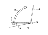
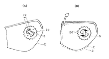
以下、図面を参照して、本発明の一実施例を説明する。図1は、本発明の一実施例に係る便器上の開閉体の電動開閉装置の概念図である。図2(A)および図2(B)は、本発明の一実施例に係る便器上の開閉体の電動開閉装置の概念を説明するための動作図であって、(A)は開閉体が全閉された状態、(B)は開閉体が開き始めた状態をそれぞれ示している。 An embodiment of the present invention will be described below with reference to the drawings. FIG. 1 is a conceptual diagram of an electric opening / closing device for an opening / closing body on a toilet according to an embodiment of the present invention. 2 (A) and 2 (B) are operation diagrams for explaining the concept of an electric opening / closing device for an opening / closing body on a toilet according to an embodiment of the present invention. A fully closed state, (B) shows a state where the opening / closing body starts to open.
図1を参照すると、本発明の一実施例に係る便器上の開閉体の電動開閉装置によれば、便器1上の開閉体2を完全に閉止された状態から開く際、まず、A区間では第1のトルクを出力する巻き込み処理が実行され、B区間では第2のトルクを出力する通常の処理が実行される。
Referring to FIG. 1, according to the electric opening / closing device of the opening / closing body on the toilet according to an embodiment of the present invention, when opening the opening /
但し、A区間は、モータと開閉体2のトルク伝達経路間にガタがある区間であって、モータが第1のトルクで駆動されても開閉体2は動かない区間である。B区間は、モータと開閉体2のトルク伝達経路間のガタが詰まり、モータが第2のトルクを出力することにより開閉体2が動き出してから、開閉体2がストッパ21に制止されるまでの区間である。第1のトルクは、閉止された開閉体2を開く際、開閉体2を動かすために必要なトルクよりも小さくかつモータと開閉体2のトルク伝達経路間のガタを詰めるのに必要なトルクよりは大きいトルクである。第2のトルクは、開閉体2を動かすために必要なトルクよりも大きいトルクである。
However, section A is a section in which there is a backlash between the torque transmission path of the motor and the opening /
図2(A)は、図1のA区間に対応する動作図であって、A区間は、モータと開閉体2(開閉体被付勢部20)のトルク伝達経路間のガタが詰まるまでの区間である。このA区間では、第1のトルク(ガタ詰め用出力)により、モータ回転軸5が回転させられる。
FIG. 2A is an operation diagram corresponding to the A section of FIG. 1, in which the backlash between the motor and the torque transmission path of the opening / closing body 2 (opening / closing body biased portion 20) is blocked. It is a section. In section A, the
図2(B)は、図1のB区間に対応する動作図であって、B区間は、前記ガタが詰まった後の区間である。このB区間では、第2のトルクにより、モータ回転軸5が回転させられる。
FIG. 2B is an operation diagram corresponding to the B section in FIG. 1, and the B section is a section after the play is clogged. In this B section, the
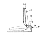
図3は、本発明の一実施例に係る便器上の開閉体の電動開閉装置を内蔵する便器の側面図である。図4は、図3に示した便器に内蔵される電動開閉装置の側面拡大図である。 FIG. 3 is a side view of a toilet having a built-in electric opening / closing device for an opening / closing body on the toilet according to one embodiment of the present invention. FIG. 4 is an enlarged side view of the electric switchgear built in the toilet shown in FIG.
図3を参照すると、便器1上には、開閉体として、便座3および便蓋4が配置されている。便座3および便蓋4の電動開閉は制御手段10によって制御される。便座3および便蓋4は、開閉体軸2aを回転軸として開閉される。
Referring to FIG. 3, a toilet seat 3 and a toilet lid 4 are disposed on the toilet 1 as an opening / closing body. The electric opening and closing of the toilet seat 3 and the toilet lid 4 is controlled by the control means 10. The toilet seat 3 and the toilet lid 4 are opened and closed with the opening /
図4を参照すると、本発明の一実施例に係る便器上の開閉体の電動開閉装置は、駆動源であるモータMと、モータMが出力するトルクを便器1上の開閉体2に伝達する伝達機構(多段減速歯車列)8と、モータM、特にモータ回転軸5の回転速度を検出する検出手段であるホールIC9と、ホールIC9による検出に基づいてモータMのトルクを制御する制御手段(マイクロコンピュータ)10と、を有している。
Referring to FIG. 4, an electric opening / closing device for an opening / closing body on a toilet according to an embodiment of the present invention transmits a motor M as a driving source and a torque output from the motor M to the opening /
制御手段10は、閉止された開閉体2を開く際、最初はモータMに開閉体2を動かすために必要なトルクよりも小さくかつモータMと開閉体2のトルク伝達経路間のガタを詰めるのに必要なトルクよりは大きい第1のトルクを出力させ、その後、ホールIC9が少なくともモータ回転速度の低下を検出すると、開閉体2を動かすために必要なトルクよりも大きい第2のトルクを出力させる。
When the control means 10 opens the closed opening /
制御手段10には、ホールIC9から出力されるモータ回転速度に対応する検出信号(ホールIC信号)11が入力される。制御手段10は検出信号11に基づいて、モータMが出力するトルクを制御する制御信号12を出力する。本実施例において、モータMはPWM制御され、デューティ比が高いほど、モータMが出力するトルクは大きくなる。
A detection signal (Hall IC signal) 11 corresponding to the motor rotation speed output from the Hall IC 9 is input to the control means 10. Based on the detection signal 11, the control means 10 outputs a
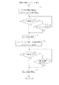
次に、以上説明した本発明の一実施例に係る便器上の開閉体の電動開閉装置の動作を説明する。図5は、図4に示した電動開閉装置の動作を説明するためのフローチャートである。図6は、図4に示した電動開閉装置の動作を説明するためのタイミングチャートである。 Next, the operation of the electric opening / closing device for the opening / closing body on the toilet according to the embodiment of the present invention described above will be described. FIG. 5 is a flowchart for explaining the operation of the electric switchgear shown in FIG. FIG. 6 is a timing chart for explaining the operation of the electric switchgear shown in FIG.
図5を参照すると、閉止されている開閉体を開く際、ステップS1で、制御手段10は、ガタ詰め用出力値(第1のトルク)を指定してモータMを駆動すると共に、ガタ詰め期間制限タイマのカウントを開始する。例えば、制御手段10は、10%のデューティ比でモータMをPWM制御によって駆動する。10%のデューティ比では、開閉体2は動かない。
Referring to FIG. 5, when opening the closed opening / closing body, in step S <b> 1, the control means 10 designates an output value (first torque) for backlashing and drives the motor M, and the backlashing period. Start counting of the limit timer. For example, the control means 10 drives the motor M by PWM control with a duty ratio of 10%. At a duty ratio of 10%, the opening /
ステップS2で、制御手段10は、ホールIC9が出力する検出信号(ホールIC信号)11のH/L間隔により、モータMの回転速度を判定し、H/Lの切り替わりが所定時間以上ない場合、ガタが詰まった(モータ回転軸5がロックした)と判定し、ステップS4の処理に移行する。一方、制御手段10は、H/Lの切り替わりがある場合(モータ回転軸5が回転中の場合)、ステップS3の処理に移行し、前記タイマがタイムアップしていなければ、ステップS2の処理に戻り、タイムアップしていれば、開閉体2が電動で開かない現象を防止するため、ステップS4の処理に移行する。
In step S2, the control means 10 determines the rotational speed of the motor M based on the H / L interval of the detection signal (Hall IC signal) 11 output from the Hall IC 9, and if the H / L switching does not exceed a predetermined time, It is determined that the backlash is clogged (the
制御手段10は、ステップS4でモータMを出力停止にし、すぐに、ステップS5で、開閉体2を駆動するための出力値(第2のトルク)を指定してモータMを駆動する。例えば、制御手段10は、100%のデューティ比でモータMをPWM制御によって駆動する。なお、制御手段10は、検出信号11、すなわち、モータ回転軸5の回転速度に基づいて、デューティ比をフィードバック制御することが好ましい。
The control means 10 stops the output of the motor M in step S4, and immediately specifies the output value (second torque) for driving the opening /
ステップS6で、制御手段10は、ホールIC9が出力する検出信号11のH/L間隔により、モータMの回転速度を判定する。制御手段10は、H/Lの切り替わりが所定時間以上ない場合、開閉体2がロックされた、例えば、開閉体2が図1のストッパ21によって制止された、或いは人手により制止されたと判定し、ステップS8に移行してモータMを出力停止にし、H/Lの切り替わりがある場合(開閉体2が回動中の場合)、ステップS7に移行する。ステップS7で、制御手段10は、ホールIC9が出力する検出信号11のH/L切り替わり回数をカウントし、H/Lの切り替わり回数が制限値を超えた場合は、ステップS8に移行してモータMを出力停止にし、超えていない場合はステップS6に戻る。
In step S6, the control means 10 determines the rotational speed of the motor M based on the H / L interval of the detection signal 11 output from the Hall IC 9. The control means 10 determines that the opening /
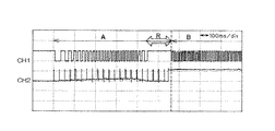
以上のフローチャートに従い、実機で便座および便蓋を開く実験を行った。図6中、CH1はモータ回転軸5の回転速度を示す検出信号11の波形であり、CH2は、モータMに駆動制御するためのPWM信号のデューティ比を示す制御信号12の波形である。デューティ比はA区間で10%、B区間で100%とした。図5のステップS2のロック検出期間は100msとした。
According to the above flowchart, an experiment was conducted to open the toilet seat and toilet lid with the actual machine. In FIG. 6, CH1 is a waveform of the detection signal 11 indicating the rotation speed of the
図6を参照すると、ガタを詰めるA区間では、便座および便蓋は動かずガタのみが詰められ、ガタが詰まった後の約100msのロック期間R、モータ回転軸は停止した。続いて、デューティを上げると、すなわち、B区間で、モータ回転軸が再度動き出し、さらに、便座および便蓋が開き始めた。ガタを詰めるA区間では、特に、その終了時、モータと便座等の間を接続する伝達機構、例えば、減速歯車列等のガタ打ち音がなく、A区間からB区間に遷移するときも便座等の開閉体はスムーズな動作フィーリングで開いた。また、この実験を繰り返したところ、同様の効果が繰り返し再現された。 Referring to FIG. 6, in section A where the backlash is packed, the toilet seat and the toilet lid do not move and only the backlash is packed, and the motor rotation shaft is stopped for about 100 ms after the backlash is jammed. Subsequently, when the duty was increased, that is, in the B section, the motor rotating shaft started moving again, and the toilet seat and toilet lid began to open. In the A section where the backlash is packed, especially at the end, there is no rattling sound such as a transmission mechanism connecting the motor and the toilet seat, for example, a reduction gear train, and the toilet seat etc. also when transitioning from the A section to the B section The opening and closing body of the door opened with a smooth motion feeling. Moreover, when this experiment was repeated, the same effect was reproduced repeatedly.
本発明は、便座および/または便蓋の自動開閉装置に好適に適用される。また、本発明は、多段の減速機構、例えば、多段の減速歯車機構によってモータのトルクを減速して便座および/または便蓋に伝達する装置に好適に適用される。 The present invention is suitably applied to an automatic opening / closing device for a toilet seat and / or a toilet lid. Further, the present invention is preferably applied to a device that reduces the torque of a motor and transmits it to a toilet seat and / or toilet lid by a multistage reduction mechanism, for example, a multistage reduction gear mechanism.
1 便器
2 開閉体
2a 開閉体軸
3 便座
4 便蓋
5 モータ回転軸(モータ出力軸)
6 ウォームギヤ
7 ウォームホイール
8 伝達機構(多段減速歯車列)
9 ホールIC(検出手段)
10 制御手段(モータ制御手段、マイクロコンピュータ)
11 検出信号(ホールIC信号)
12 制御信号(PWM信号)
20 開閉体被付勢部
21 ストッパ
A ガタを詰める区間
B 開閉体を動かす区間
R ロック期間
M モータ
DESCRIPTION OF SYMBOLS 1
6 Worm gear 7
9 Hall IC (detection means)
10 Control means (motor control means, microcomputer)
11 Detection signal (Hall IC signal)
12 Control signal (PWM signal)
20 Opening / Closing Body Energized
Claims (3)
前記モータが出力するトルクを便器上の開閉体に伝達する伝達機構と、
前記モータの回転速度を検出する検出手段と、
前記検出手段による前記検出に基づいて前記モータの前記トルクを制御する手段であって、閉止された前記開閉体を開く際、最初は前記モータに前記開閉体を動かすために必要なトルクよりも小さくかつ前記モータと前記開閉体のトルク伝達経路間のガタを詰めるのに必要なトルクよりは大きい第1のトルクを出力させ、その後、前記検出手段が少なくとも前記回転速度の低下を検出すると、前記開閉体を動かすために必要なトルクよりも大きい第2のトルクを出力させる制御手段と、
を有する、ことを特徴とする便器上の開閉体の電動開閉装置。 A motor as a drive source;
A transmission mechanism for transmitting torque output by the motor to an opening / closing body on the toilet;
Detecting means for detecting the rotational speed of the motor;
A means for controlling the torque of the motor based on the detection by the detection means, and when the closed opening / closing body is opened, the torque is initially smaller than the torque required for the motor to move the opening / closing body. And outputting a first torque larger than the torque necessary to close the backlash between the motor and the torque transmission path of the opening / closing body, and then detecting the decrease in the rotational speed when the detection means detects at least the decrease in the rotational speed. Control means for outputting a second torque larger than a torque required for moving the body;
An electric switchgear for an openable / closable body on a toilet bowl.
Priority Applications (1)
| Application Number | Priority Date | Filing Date | Title |
|---|---|---|---|
| JP2007079289A JP2008237331A (en) | 2007-03-26 | 2007-03-26 | Electric opening/closing device of opening/closing body on toilet bowl |
Applications Claiming Priority (1)
| Application Number | Priority Date | Filing Date | Title |
|---|---|---|---|
| JP2007079289A JP2008237331A (en) | 2007-03-26 | 2007-03-26 | Electric opening/closing device of opening/closing body on toilet bowl |
Publications (2)
| Publication Number | Publication Date |
|---|---|
| JP2008237331A true JP2008237331A (en) | 2008-10-09 |
| JP2008237331A5 JP2008237331A5 (en) | 2011-07-07 |
Family
ID=39909393
Family Applications (1)
| Application Number | Title | Priority Date | Filing Date |
|---|---|---|---|
| JP2007079289A Pending JP2008237331A (en) | 2007-03-26 | 2007-03-26 | Electric opening/closing device of opening/closing body on toilet bowl |
Country Status (1)
| Country | Link |
|---|---|
| JP (1) | JP2008237331A (en) |
Cited By (2)
| Publication number | Priority date | Publication date | Assignee | Title |
|---|---|---|---|---|
| JP2018201646A (en) * | 2017-05-31 | 2018-12-27 | アイシン精機株式会社 | Toilet seat device |
| JP2020162691A (en) * | 2019-03-28 | 2020-10-08 | 日本電産サンキョー株式会社 | Opening/closing member drive device and toilet lid opening/closing unit |
Citations (2)
| Publication number | Priority date | Publication date | Assignee | Title |
|---|---|---|---|---|
| JP2006101933A (en) * | 2004-09-30 | 2006-04-20 | Toto Ltd | Electric opening/closing device for toilet seat or toilet lid |
| JP2006333677A (en) * | 2005-05-30 | 2006-12-07 | Nikon Corp | Ultrasonic motor control unit |
-
2007
- 2007-03-26 JP JP2007079289A patent/JP2008237331A/en active Pending
Patent Citations (2)
| Publication number | Priority date | Publication date | Assignee | Title |
|---|---|---|---|---|
| JP2006101933A (en) * | 2004-09-30 | 2006-04-20 | Toto Ltd | Electric opening/closing device for toilet seat or toilet lid |
| JP2006333677A (en) * | 2005-05-30 | 2006-12-07 | Nikon Corp | Ultrasonic motor control unit |
Cited By (3)
| Publication number | Priority date | Publication date | Assignee | Title |
|---|---|---|---|---|
| JP2018201646A (en) * | 2017-05-31 | 2018-12-27 | アイシン精機株式会社 | Toilet seat device |
| JP2020162691A (en) * | 2019-03-28 | 2020-10-08 | 日本電産サンキョー株式会社 | Opening/closing member drive device and toilet lid opening/closing unit |
| JP7319071B2 (en) | 2019-03-28 | 2023-08-01 | ニデックインスツルメンツ株式会社 | Opening/closing member driving device and toilet lid opening/closing unit |
Similar Documents
| Publication | Publication Date | Title |
|---|---|---|
| US8479445B2 (en) | Door opening/closing device | |
| EP3153651B1 (en) | Power door opening and closing device | |
| US7698855B2 (en) | Sliding-door opening control apparatus | |
| US20060168891A1 (en) | Vehicle door opening and closing apparatus | |
| US7509772B2 (en) | Vehicle door opening and closing apparatus | |
| JP3934022B2 (en) | Speed control device for vehicle opening / closing body | |
| JP2004339864A (en) | Vehicular opening-closing driving device of opening-closing body | |
| JP2004100345A (en) | Vehicular automatic opening/closing device | |
| JP2010144379A (en) | Equipment for controlling opening and closing body for vehicle | |
| JP2008237331A (en) | Electric opening/closing device of opening/closing body on toilet bowl | |
| JP2011098048A (en) | Toilet seat device | |
| JP2016050411A (en) | Drive controller for opening/closing body | |
| US10174541B2 (en) | Control apparatus for opening and closing unit for vehicle | |
| JP2009235706A (en) | Door closer unit for vehicle | |
| JP4500080B2 (en) | Vehicle door control device | |
| JP4804889B2 (en) | Door equipment | |
| JP2006057391A (en) | Vehicle door driving device | |
| KR101154298B1 (en) | Electromotive shutter device of trunk lid for vehicles | |
| JP4109528B2 (en) | Closing control device for vehicle opening / closing body | |
| JP2005090100A (en) | Closing driving device of opening/closing body | |
| JP2008237331A5 (en) | ||
| JP6182920B2 (en) | Opening and closing device for toilet lid and toilet seat | |
| JP2006078058A (en) | Door opening device and refrigerator | |
| JPH0725409Y2 (en) | Open / close gate device | |
| JP2018150725A (en) | Vehicle opening/closing body drive control device |
Legal Events
| Date | Code | Title | Description |
|---|---|---|---|
| A621 | Written request for application examination |
Free format text: JAPANESE INTERMEDIATE CODE: A621 Effective date: 20100218 |
|
| A521 | Written amendment |
Free format text: JAPANESE INTERMEDIATE CODE: A523 Effective date: 20110523 |
|
| A977 | Report on retrieval |
Effective date: 20110722 Free format text: JAPANESE INTERMEDIATE CODE: A971007 |
|
| A131 | Notification of reasons for refusal |
Free format text: JAPANESE INTERMEDIATE CODE: A131 Effective date: 20110823 |
|
| A02 | Decision of refusal |
Effective date: 20120110 Free format text: JAPANESE INTERMEDIATE CODE: A02 |